

Page 1

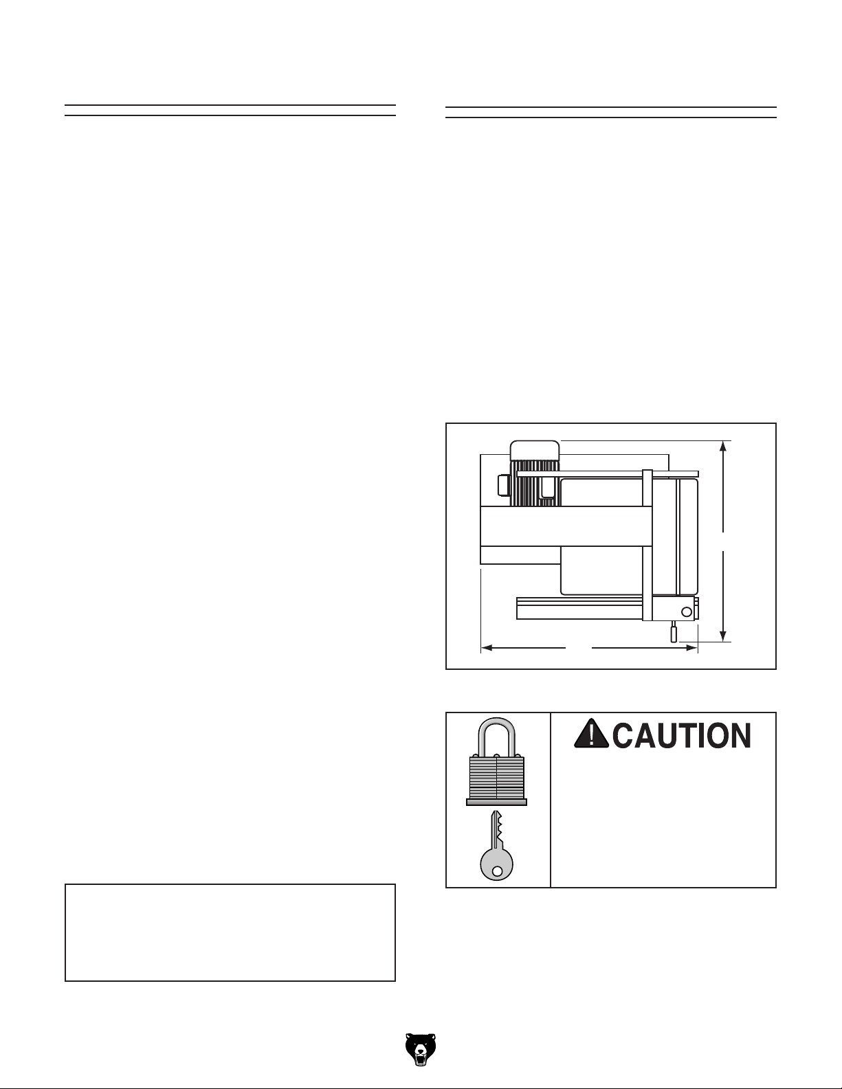
MODEL G0513 SERIES
HEAVY-DUTY 17" BANDSAW
OWNER'S MANUAL
(MODELS G0513, G0513P, G0513ANV,
& EXTREME MODELS G0513X2, G0513X2B,
G0513X2BF, & G0513X2F)
For Model
G0513X2B
Only
Model
G0513X2B
COPYRIGHT © NOVEMBER, 2012 BY GRIZZLY INDUSTRIAL, INC.
WARNING: NO PORTION OF THIS MANUAL MAY BE REPRODUCED IN ANY SHAPE
OR FORM WITHOUT THE WRITTEN APPROVAL OF GRIZZLY INDUSTRIAL, INC.
#TS15097 PRINTED IN TAIWA N
Model
G0513ANV
Page 2

This manual provides critical safety instructions on the proper setup,
operation, maintenance, and service of this machine/tool. Save this
document, refer to it often, and use it to instruct other operators.
Failure to read, understand and follow the instructions in this manual
may result in fire or serious personal injury—including amputation,
electrocution, or death.
The owner of this machine/tool is solely responsible for its safe use.
This responsibility includes but is not limited to proper installation in
a safe environment, personnel training and usage authorization,
proper inspection and maintenance, manual availability and comprehension, application of safety devices, cutting/sanding/grinding tool
integrity, and the usage of personal protective equipment.
The manufacturer will not be held liable for injury or property damage
from negligence, improper training, machine modifications or misuse.
Some dust created by power sanding, sawing, grinding, drilling, and
other construction activities contains chemicals known to the State
of California to cause cancer, birth defects or other reproductive
harm. Some examples of these chemicals are:
• Lead from lead-based paints.
• Crystalline silica from bricks, cement and other masonry products.
• Arsenic and chromium from chemically-treated lumber.
Your risk from these exposures varies, depending on how often you
do this type of work. To reduce your exposure to these chemicals:
Work in a well ventilated area, and work with approved safety equipment, such as those dust masks that are specially designed to filter
out microscopic particles.
Page 3

Table of Contents
INTRODUCTION ............................................... 3
Manual Accuracy ........................................... 3
Contact Info.................................................... 3
G0513 Series Combination Manual ............... 3
Basic Controls ................................................ 4
Control Panel ............................................... 4
Front Controls .............................................. 4
Motor Brake ................................................. 4
Rear Controls .............................................. 5
SECTION 1: SAFETY ....................................... 8
Safety Instructions for Machinery .................. 8
Additional Safety for Bandsaws ................... 10
SECTION 2: POWER SUPPLY ...................... 11
Availability .................................................. 11
Full-Load Current Rating ........................... 11
Circuit Information ..................................... 11
Circuit Requirements ................................. 12
Grounding Requirements .......................... 12
Extension Cords ........................................ 14
Voltage Conversion ................................... 14
SECTION 3: SETUP ....................................... 15
Introduction .................................................. 15
Needed for Setup ......................................... 15
Unpacking .................................................... 15
Inventory ...................................................... 16
G0513, G0513P, & G0513ANV ................. 16
G0513X2, G0513X2B, G0513X2BF, &
G0513X2F ................................................. 17
Cleanup ........................................................ 18
Site Considerations ...................................... 18
Floor Load ................................................. 18
Placement Location ................................... 18
Moving & Placing Bandsaw ......................... 19
Using Eye Bolt ........................................... 19
Using Wood Blocks ................................... 19
Mounting ...................................................... 20
Bolting to Concrete Floors ......................... 20
Assembly ..................................................... 20
Installing Guide Post Handwheel, Positive
Stop Bolt, & Table ..................................... 20
Installing Fence
(G0513, G0513P, G0513ANV, &
G0513X2F) ................................................ 22
Installing Fence
(G0513X2B & G0513X2BF) ...................... 23
Installing Foot Brake Pedal
(G0513X2BF & G0513X2F) ...................... 24
Installing Resaw Fence
(G0513X2, G0513X2B, G0513X2BF, &
G0513X2F) .................................................. 24
Initial Blade Tracking ................................... 25
Adjusting Positive Stop ................................ 26
Dust Collection ............................................. 27
Power Cord Connection
(G0513X2BF & G0513X2F) ......................... 27
Test Run ...................................................... 28
Tensioning Blade ......................................... 30
Flutter Method ........................................... 30
Deflection Method ...................................... 31
Adjusting Blade Support Bearings ............... 32
Adjusting Blade Guides ............................... 33
Adjusting Blade Guides
(G0513, G0513P, & G0513ANV) .............. 34
Adjusting Blade Guide Bearings
(G0513X2, G0513X2B, G0513X2BF, &
G0513X2F) ................................................ 35
Aligning Table .............................................. 36
Aligning Fence ............................................. 37
Aligning Fence
(G0513, G0513P, G0513ANV, G0513X2,
& G0513X2F) ............................................. 37
Aligning Fence
(G0513X2B & G0513X2BF) ...................... 38
Calibrating Miter Gauge ............................... 38
SECTION 4: OPERATIONS ........................... 39
Disabling & Locking Switch
(G0513, G0513P, G0513ANV, G0513X2) ... 39
Disabling & Locking Switch
(G0513X2B, G0513X2BF, G0513X2F) ........ 40
General Overview ........................................ 40
Straight Cuts .............................................. 40
Irregular Cuts ............................................. 40
Basic Cutting Tips ..................................... 40
Operation Overview ..................................... 41
Workpiece Inspection................................... 41
Table Tilt ...................................................... 42
Models G0513, G0513P, & G0513ANV .... 42
Models G0513X2, G0513X2B,
G0513X2BF, & G0513X2F ........................ 42
Guide Post ................................................... 43
Fine Tune Tracking ...................................... 43
Blade Selection ............................................ 44
Blade Terminology ..................................... 44
Blade Length ............................................. 44
Blade Width ............................................... 44
Blade Material ............................................ 44
Tooth Set ................................................... 45
Tooth Type ................................................ 45
Blade Selection Chart .................................. 46
Blade Breakage ........................................... 47
Blade Care & Break-In ................................. 47
Page 4

Blade Changes ............................................ 48
Removing Blade ........................................ 48
Installing Blade .......................................... 48
Blade Speed ................................................ 49
Crosscutting ................................................. 50
Resawing ..................................................... 50
Cutting Curves ............................................. 51
Stacked Cuts................................................ 52
SECTION 5: ACCESSORIES ......................... 53
SECTION 6: MAINTENANCE ......................... 55
Schedule ...................................................... 55
Wheel Brush ................................................ 55
Cleaning & Protecting .................................. 55
Lubrication ................................................... 55
Blade Post Rack ........................................ 55
Tension Adjustment Assembly .................. 56
Trunnions ................................................... 56
SECTION 7: SERVICE ................................... 57
Troubleshooting ........................................... 57
V-Belt Service .............................................. 60
Checking V-Belt ......................................... 60
Replacing V-Belt ........................................ 60
Blade Lead ................................................... 61
Adjusting Wheel Brush ................................ 62
Adjusting Tension Lever .............................. 62
Adjusting Guide Post Travel ........................ 63
Checking/Adjusting Guide Post Parallel
with Blade Side-to-Side ............................. 63
Checking/Adjusting Guide Post Parallel
with Blade Front-to-Back ........................... 64
Aligning Wheels ........................................... 65
Checking Coplanarity ................................ 65
Shimming Upper Wheel ............................ 66
Adjusting Lower Wheel .............................. 67
Magnetic Brake Adjustment
(G0513X2B, G0513X2BF) ........................... 67
SECTION 8: WIRING ...................................... 68
Wiring Safety Instructions ............................ 68
G0513, G0513P, G0513ANV, & G0513X2
Wiring Diagram ............................................ 69
G0513X2B Wiring Diagram ......................... 70
G0513X2BF Wiring Diagram ....................... 71
G0513X2F 220V Wiring Diagram ................ 72
G0513X2F 110V Wiring Diagram ................ 73
SECTION 9: PARTS ....................................... 74
G0513/G0513P/G0513ANV Main ................ 74
G0513/G0513P/G0513ANV
Table, Trunnion, & Lower Blade Guides...... 76
G0513/G0513P/G0513ANV Fence .............. 77
G0513/G0513P/G0513ANV
Upper Blade Guides & Miter Gauge ............ 78
G0513 Labels............................................... 80
G0513P Labels ............................................ 81
G0513ANV Labels ....................................... 82
G0513X2 Main ............................................. 83
G0513X2 Labels .......................................... 85
G0513X2B Main........................................... 86
G0513X2B Labels ........................................ 89
G0513X2BF Main ........................................ 90
G0513X2BF Labels...................................... 93
G0513X2F Main ........................................... 94
G0513X2F Labels ........................................ 97
G0513X2, G0513X2B, G0513X2BF, &
G0513X2F
Guides & Trunnions ..................................... 98
G0513X2 & G0513X2F
Fence Assembly & Table ........................... 100
G0513X2B & G0513X2BF
Fence Assembly & Table ........................... 101
G0513X2BF & G0513X2F
Foot Brake ................................................. 102
WARRANTY & RETURNS ........................... 105
Page 5

INTRODUCTION
We are proud to offer this manual with your new
machine! We've made every effort to be exact
with the instructions, specifications, drawings,
and photographs of the machine we used when
writing this manual. However, sometimes we still
make
Also, owing to our policy of continuous improvement, your machine may not exactly match the
manual. If you find this to be the case, and the dif-
ference between the manual and machine leaves
you in doubt,
manual update or call technical support for help.
Before calling, find the manufacture date of your
machine by looking at the date stamped into the
machine ID label (see below). This will help us
determine if the manual version you received
matches the manufacture date of your machine.
For your convenience, we
-
uals and
on our website
at
model
of
as soon as they are complete.
We stand behind our machines. If you have
any questions or need help, use the information
below to contact us. Before contacting, please get
the serial number and manufacture date of your
machine. This will help us help you faster.
We want your feedback on this manual. What did
you like about it? Where could it be improved?
Please take a few minutes to give us feedback.
Email: manuals@grizzly.com
Manual Accuracy
an occasional mistake.
www.grizzly.com. Any updates to your
machine will be reflected in these documents
check our website for the latest
Manufacture Date
of Your Machine
post all available man
manual updates for free
Contact Info
Grizzly Technical Support
1203 Lycoming Mall Circle
Muncy, PA 17756
Phone: (570) 546-9663
Email: techsupport@grizzly.com
Grizzly Documentation Manager
P.O. Box 2069
Bellingham, WA 98227-2069
G0513 Series
Combination Manual
The G0513 Series Bandsaws share many similarities. Thus, this combination manual includes information for all seven models of the G0513 Series
Bandsaws.
Unless otherwise specified, information applies to
all models. Headers are used to identify information that only applies to specific models.
G0513 Series Bandsaws
-3-
Page 6
Basic Controls
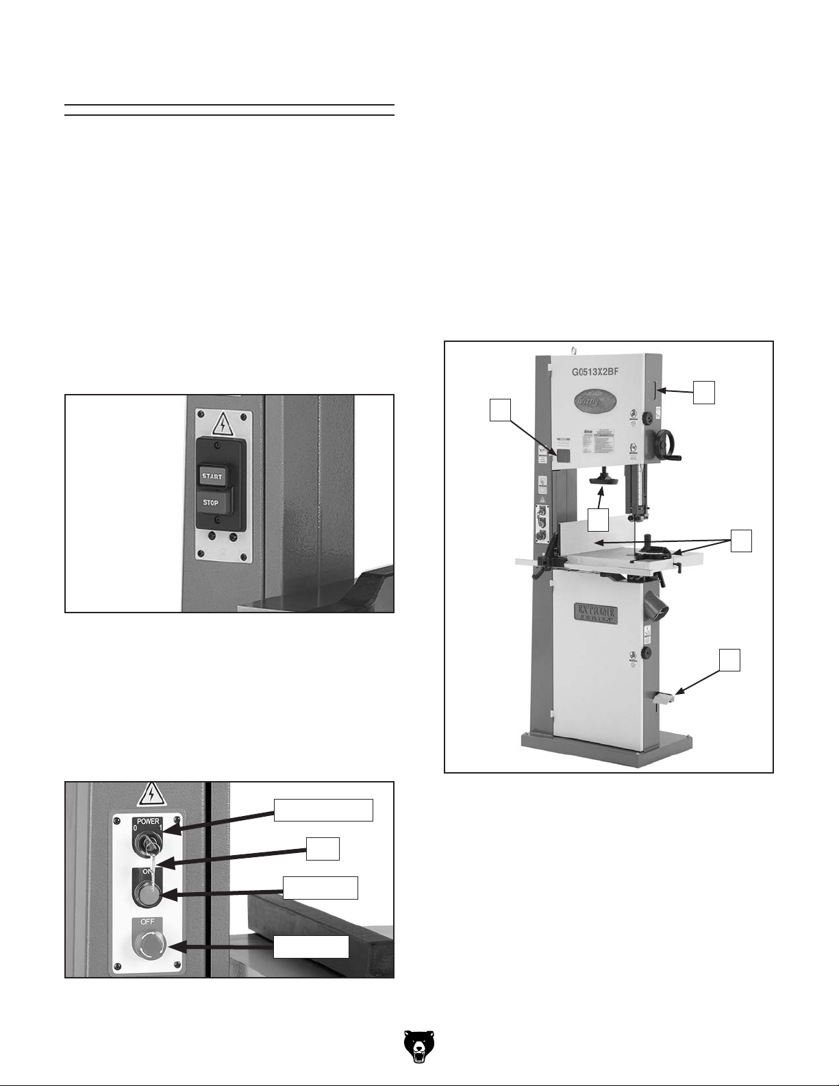
Refer to Figures 1–4 and the following descrip-
tions to become familiar with the basic controls
and components of your bandsaw. Knowledge of
these controls and terminology will help you better
understand this manual.
Control Panel
The 2-button power switch on Models G0513,
G0513P, and G0513X2 is located on the column
for easy access (see Figure 1). The power button
can be disabled with a padlock to prevent unauthorized startup of the bandsaw (refer to Page 39
for additional details).
Front Controls
A. Blade Tension Scale: Allows for easy moni-
toring of blade tension in arbitrary numbers
1–8.
B. Blade Tension Handwheel: Tensions blade
in gradual increments.
C. Blade Tracking Window: Allows you to
monitor blade tracking on the wheel without
opening the wheel cover.
D. Fence and Miter Gauge: Supports workpiece
for controlled straight or angled cuts.
C
A
Figure 1. 2-Button power switch.
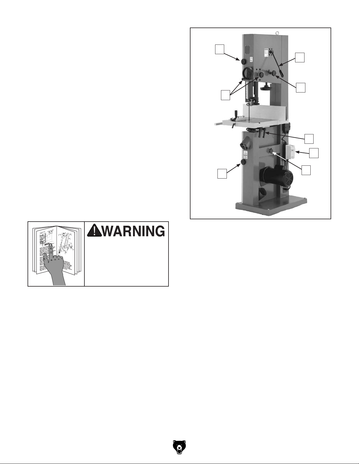
The Models G0513X2B, G0513X2BF, and
G0513X2F feature a power switch that can be
disabled with a key to prevent unauthorized starting of the machine (see Figure 2). To disable the
switch, turn the key to "0" and remove it. To enable
the switch, insert the key and turn it to "1."
Power Switch
Key
On Button
B
D
E
Figure 3. Front controls
(G0513X2BF shown).
E. Foot Brake (Models G0513X2BF &
G0513X2F): Quickly stops bandsaw blade
and motor.
Off Button
Figure 2. Control panel with a switch disabling
lock.
-4-
Motor Brake
The Models G0513X2B and G0513X2BF have a
motor brake that activates and quickly stops the
blade when the OFF button is used, or the foot
pedal is pressed on the Model G0513X2BF.
G0513 Series Bandsaws
Page 7
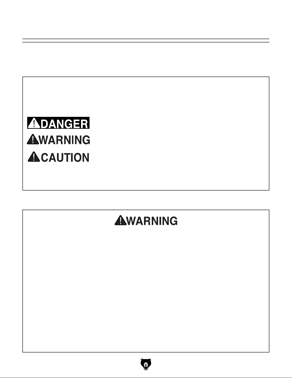
Rear Controls
F. Wheel Cover Lock Knobs: Secure the
wheel covers.
G. Quick-Release Blade Tension Lever:
Adjusts blade tension for quick blade changes.
H. Blade Tracking Knob and Lock Lever:
Moves and locks upper wheel tilt for blade
tracking.
I. Table Tilt Controls: Adjusts table tilt and
locks the table in place.
J. Magnetic Switch: Provides thermal overload
protection for the motor.
F
G
H
L
I
J
K. Lower Wheel Adjustment Hub: Used when
adjusting coplanarity of the wheels.
L. Guide Post Handwheel and Lock Knob:
Quickly moves the upper guide post to the
desired height; locks setting.
To reduce the risk of
serious injury when using
this machine, read and
understand this entire
manual before beginning
any operations.
F
Figure 4. Rear controls
(G0513X2B shown).
K
G0513 Series Bandsaws
-5-
Page 8

MODEL G0513 SERIES 17" BANDSAWS
Model Number
Product Dimensions
Weight 266 lbs. 325 lbs. 352 lbs. 357 lbs. 335 lbs.
Width (side-to-side) x Depth
(front-to-back) x Height
Footprint (Length x Width) 27" x 17
Shipping Dimensions
Type Wood Slat Crate
Weight 342 lbs. 418 lbs . 446 lbs. 460 lbs. 434 lbs.
Length x Width x Height 20" x 30" x 81" 31" x 21" x 81" 31" x 20" x 81" 31" x 21" x 81"
Electrical
Power Requirement 110V/220V, Single-Phase, 60 Hz 220V, Single-Phase, 60 Hz
Full Load Current
Minimum Circuit Size 30A at 110V, 15A at 220V 15A
Prewired 220V
Switch 2-Button Power Switch Magnetic w/Thermal Overload Protection
Switch Voltage 110V/220V 220V 110V/220V
Cord Included Yes No
Plug Included No Yes, NEMA 6-15 No
Motor
Type TEFC Capacitor Start Induction
Horsepower 2 HP
Voltage 110V/220V 220V 110V/220V
Phase Single-Phase
Amperage
Speed 172 5 RPM
Cycle 60 Hz
Power Transfer Belt Drive
Bearings Shielded and Permanently Lubricated
Operation
Blade Speeds 1700, 3500 FPM
Table Tilt
G0513 / G0513P/
G0513ANV
20A at 110V,
10A at 220V
20A at 110V,
10A at 220V
Left 10°, Right
45°
G0513X 2 G0513X 2B G0513X 2BF G0513X 2F
32" x 32" x 73"
3
⁄4"
110V/220V,
Single-Phase,
60 Hz
19A at 110V,
9.5A at 220V
19A at 110V,
9.5A at 220V
8.7A 10A
8.7A 10A
Left 5°, Right 45°
20A at 110V, 10A
at 220V
30A at 110V, 15A
at 220V
20A at 110V, 10A
at 220V
-6-
G0513 Series Bandsaws
Page 9

Model Number
G0513 / G0513P/
G0513ANV
G0513X 2 G0513X 2B G0513X 2BF G0513X 2F
Cutting Capacities
1
Maximum Cutting Height 12
Maximum Capacity Left of
Blade
⁄8 " 1 2 "
1
16
⁄4"
Blade Information
1
1
⁄8 "–1"
⁄2 "
Ball Bearings
Standard Blade Length 131
Blade Width Range
Blade Guides
Roller Disc, Ball
Bearings
Guide Post Size 1.18" (30mm) Square
Guide Post Type Square Tubing, 0.075" in Wall Thickness
Table Dimensions
1
Length x Width x Thickness 17" x 17" x 1
Floor to Table Height 37
⁄2 " 23 5⁄8 " x 17 1⁄4" x 1 1⁄2 "
1
⁄2 "
Fence Information
Locks in Front Yes
Locks in Rear No
Adjustable for Blade Lead Yes
Resaw Fence Included No Yes
Construction
Table Precision-Ground Cast Iron
Fence
Deluxe Extruded
Aluminum
Cast Iron Fence w/ Extruded Aluminum Resaw Fence
Body Reinforced Steel
Computer-
Wheels
Balanced Cast
Computer-Balanced Cast Iron
Aluminum
Wheel Tire Polyurethane
Wheel Covers Pre-Formed Steel
Paint Powder Coated
Other Related Information
Foot Brake No Ye s
Motor Brake No Yes No
3
Wheel Diameter 16
Wheel Width 1
⁄4"
1
⁄4"
Dust Ports 2 at 4"
Mobile Base Model D2 0 57A
Other Specifications
Country of Origin Taiwan
Warranty 1 Year
ISO Factory Ye s
Serial Number Location ID Label on Upper Wheel Cover
Assembly Time 1 Hour
G0513 Series Bandsaws
-7-
Page 10
SECTION 1: SAFETY
For Your Own Safety, Read Instruction
Manual Before Operating This Machine
The purpose of safety symbols is to attract your attention to possible hazardous conditions.
This manual uses a series of symbols and signal words intended to convey the level of importance of the safety messages. The progression of symbols is described below. Remember that
safety messages by themselves do not eliminate danger and are not a substitute for proper
accident prevention measures. Always use common sense and good judgment.
Indicates an imminently hazardous situation which, if not avoided,
WILL result in death or serious injury.
Indicates a potentially hazardous situation which, if not avoided,
COULD result in death or serious injury.
Indicates a potentially hazardous situation which, if not avoided,
MAY result in minor or moderate injury. It may also be used to alert
against unsafe practices.
This symbol is used to alert the user to useful information about
NOTICE
proper operation of the machine.
Safety Instructions for Machinery
OWNER’S MANUAL. Read and understand this
owner’s manual BEFORE using machine.
TRAINED OPERATORS ONLY. Untrained operators have a higher risk of being hurt or killed.
Only allow trained/supervised people to use this
machine. When machine is not being used, disconnect power, remove switch keys, or lock-out
machine to prevent unauthorized use—especially
around children. Make workshop kid proof!
DANGEROUS ENVIRONMENTS. Do not use
machinery in areas that are wet, cluttered, or have
poor lighting. Operating machinery in these areas
greatly increases the risk of accidents and injury.
MENTAL ALERTNESS REQUIRED. Full mental
alertness is required for safe operation of machinery. Never operate under the influence of drugs or
alcohol, when tired, or when distracted.
ELECTRICAL EQUIPMENT INJURY RISKS. You
can be shocked, burned, or killed by touching live
electrical components or improperly grounded
machinery. To reduce this risk, only allow qualified
service personnel to do electrical installation or
repair work, and always disconnect power before
accessing or exposing electrical equipment.
DISCONNECT POWER FIRST.
nect machine from power supply BEFORE making
adjustments, changing tooling, or servicing machine.
This prevents an injury risk from unintended startup
or contact with live electrical components.
EYE PROTECTION. Always wear ANSI-approved
safety glasses or a face shield when operating or
observing machinery to reduce the risk of eye
injury or blindness from flying particles. Everyday
eyeglasses are not approved safety glasses.
Always discon-
-8-
G0513 Series Bandsaws
Page 11

WEARING PROPER APPAREL. Do not wear
clothing, apparel or jewelry that can become
entangled in moving parts. Always tie back or
coverlong hair.Wearnon-slip footwearto avoid
accidentalslips,whichcouldcauselossofworkpiececontrol.
hAzARdOus dusT. Dust created while using
machinery may cause cancer, birth defects, or
long-term respiratory damage. Beaware ofdust
hazardsassociatedwitheachworkpiecematerial,
andalwayswearaNIOSH-approvedrespiratorto
reduceyourrisk.
hEARING PROTECTION. Always wear hearing protectionwhen operating or observingloud
machinery. Extended exposure to this noise
withouthearing protectioncan causepermanent
hearingloss.
REMOVE AdJusTING TOOLs. Tools left on
machinery can become dangerous projectiles
uponstartup.Neverleavechuckkeys,wrenches,
or any other tools on machine. Always verify
removalbeforestarting!
INTENdEd usAGE. Only use machine for its
intendedpurposeand never makemodifications
not approved by Grizzly. Modifying machine or
using it differently than intended may result in
malfunctionormechanicalfailurethatcanleadto
seriouspersonalinjuryordeath!
AWKWARd POsITIONs. Keep proper footing
andbalanceatalltimeswhenoperatingmachine.
Donotoverreach!Avoidawkwardhandpositions
that makeworkpiece control difficult orincrease
the
riskofaccidentalinjury.
ChILdREN & BYsTANdERs. Keepchildrenand
bystandersatasafedistancefromtheworkarea.
Stopusingmachineiftheybecomeadistraction.
FORCING MAChINERY.Donot force machine.
Itwill dothe job safer and better at therate for
whichitwasdesigned.
NEVER sTANd ON MAChINE. Serious injury
may occur if machine is tipped or if the cutting
toolisunintentionallycontacted.
sTABLE MAChINE. Unexpectedmovementduring operation greatly increases risk of injury or
lossofcontrol.Beforestarting,verifymachineis
stableandmobilebase(ifused)islocked.
usE RECOMMENdEd ACCEssORIEs.Consult
thisowner’smanualorthemanufacturerforrecommended accessories. Usingimproper accessorieswillincreasetheriskofseriousinjury.
uNATTENdEd OPERATION. To reduce the
risk of accidentalinjury, turn machine off and
ensure all moving parts completely stop before
walking away. Never leave machine running
whileunattended.
MAINTAIN WITh CARE.Followallmaintenance
instructions and lubrication schedules to keep
machine in good working condition. A machine
that is improperly maintained could malfunction,
leading
ChECK dAMAGEd PARTs. Regularly inspect
machine for any condition that may affect safe
operation.Immediatelyrepairorreplacedamaged
ormis-adjustedpartsbeforeoperatingmachine.
MAINTAIN POWER CORds. When disconnecting cord-connected machines from power, grab
andpulltheplug—NOTthecord.Pullingthecord
may damage the wires inside. Do not handle
cord/plug with wethands.Avoidcord damageby
keepingitawayfromheatedsurfaces,hightraffic
areas,harshchemicals,andwet/damplocations.
toseriouspersonalinjuryordeath.
GuARds & COVERs.Guardsandcoversreduce
accidental contact with moving parts or flying
debris. Make sure they are properly installed,
undamaged,andworkingcorrectly.
G0513 Series Bandsaws
EXPERIENCING dIFFICuLTIEs. If at any time
youexperiencedifficultiesperformingtheintendedoperation,stopusingthemachine!Contactour
TechnicalSupportat(570)546-9663.
-9-
Page 12

Additional Safety for Bandsaws
BLADE CONDITION. Do not operate with dull,
cracked or badly worn blade. Dull blades require
more effort to perform the cut and increase the
risk of kickback. Inspect blades for cracks and
missing teeth before each use.
BLADE REPLACEMENT. To avoid mishaps that
could result in operator injury, make sure the blade
teeth face down toward the table and the blade is
properly tensioned and tracked before operating.
SMALL WORKPIECE HANDLING. If your hands
slip during a cut while holding small workpieces
with your fingers, serious personal injury could
occur. Always support/feed the workpiece with
push sticks, jig, vise, or some type of clamping
fixture.
BLADE SPEED. Moving the workpiece against
a blade that is not at full speed could cause the
blade to grab the workpiece and draw the operator's hands into the blade. Always allow the blade
to reach full speed before starting the cut.
WORKPIECE SUPPORT. If the workpiece should
unexpectedly twist during cutting, it could kickback or draw the operator's hands into the blade.
Always keep the workpiece flat and firm against
the table when cutting. If necessary, use a jig or
other work-holding device.
BLADE SUPPORT. The blade tension and
guides/support bearings keep the blade straight
when cutting. Always keep the blade tension,
blade guides, and support bearings properly
adjusted and positioned to avoid the blade bending or breaking with the forces of the cutting
operation.
CUTTING TECHNIQUES. Plan your operation
so the blade always cuts to the outside of the
workpiece. DO NOT back the workpiece away
from the blade while the saw is running, which
could cause kickback and personal injuries. If you
need to back the workpiece out, turn the bandsaw
OFF and wait for the blade to come to a complete
stop. DO NOT twist or put excessive stress on the
blade that could damage it.
HAND PLACEMENT. Never position fingers or
hands in line with the blade. If the workpiece or
your hands slip, serious personal injury could
occur.
FEED RATE. To avoid the risk of the workpiece
slipping and causing operator injury, always feed
stock evenly and smoothly. DO NOT force or twist
the blade while cutting, especially when sawing
small curves.
WORKPIECE MATERIAL. This machine is
intended for cutting natural and man-made wood
products, and laminate covered wood products.
This machine is NOT designed to cut metal, glass,
stone, tile, etc.
BLADE CONTROL. To avoid serious personal
injury, DO NOT attempt to stop or slow the blade
with your hand or the workpiece. Allow the blade
to stop on its own.
UPPER BLADE GUIDE SUPPORT. To reduce
the exposure of the operator to the blade and
provide maximum support for the blade, keep the
upper blade guides and support bearing no more
than 1" above the workpiece.
Like all machinery there is potential danger when operating this machine. Accidents are frequently caused by lack of familiarity or failure to pay attention. Use this machine with respect
and caution to decrease the risk of operator injury. If normal safety precautions are overlooked
or ignored, serious personal injury may occur.
-10 -
G0513 Series Bandsaws
Page 13

SECTION 2: POWER SUPPLY
Before installing the machine, consider the availability and proximity of the required power supply
circuit. If an existing circuit does not meet the
requirements for this machine, a new circuit must
be installed. To minimize the risk of electrocution,
fire, or equipment damage, installation work and
electrical wiring must be done by an electrican or
qualified service personnel in accordance with all
applicable codes and standards.
Electrocution, fire, or
equipment damage may
occur if machine is not
correctly grounded and
connected to the power
The full-load current rating is the amperage a
machine draws at 100% of the rated output power.
On machines with multiple motors, this is the
amperage drawn by the largest motor or sum of all
motors and electrical devices that might operate
at one time during normal operations.
The full-load current is not the maximum amount
of amps that the machine will draw. If the machine
is overloaded, it will draw additional amps beyond
the full-load rating.
If the machine is overloaded for a sufficient length
of time, damage, overheating, or fire may result—
especially if connected to an undersized circuit.
To reduce the risk of these hazards, avoid overloading the machine during operation and make
sure it is connected to a power supply circuit that
meets the requirements in the following section.
Note: The circuit requirements listed in this manual apply to a dedicated circuit—where only one
machine will be running at a time. If this machine
will be connected to a shared circuit where multiple machines will be running at the same time,
consult a qualified electrician to ensure that the
circuit is properly sized for safe operation.
A power supply circuit includes all electrical
equipment between the breaker box or fuse panel
in the building and the machine. The power supply circuit used for this machine must be sized to
safely handle the full-load current drawn from the
machine for an extended period of time. (If this
machine is connected to a circuit protected by
fuses, use a time delay fuse marked D.)
Availability
Circuit Information
supply.
Full-Load Current Rating
G0513, G0513P, G0513ANV, & G0513X2F
Full-Load Current Rating
At 110V ..................................................20 Amps
At 220V .................................................10 Amps
G0513X2 Full-Load Current Rating
At 110V .................................................. 19 Amps
At 220V ................................................9.5 Amps
G0513X2B Full-Load Current Rating
At 220V ........................................................ 8 .7A
G0513X2BF Full-Load Current Rating
At 220V ......................................................... 10A
G0513 Series Bandsaws
-11-
Page 14
This machine MUST be grounded. In the event
of certain malfunctions or breakdowns, grounding
reduces the risk of electric shock by providing a
path of least resistance for electric current.
Circuit Requirements
These machines are prewired to operate on a 220V power supply circuit that has a verified ground and meet
the 220V operation requirements listed below.
Models G0513, G0513P, G0513ANV, G0513X2, and G0513X2F can be converted to operate on a 110V
power supply (refer to Voltage Conversion instructions beginning on Page 69) that has a verified ground
and meet the 220V operation requirements listed below.
Model Number
Circuit Requirements For 220V Operation:
Nominal Voltage 220V/240V
Cycle 60 Hz
Phase Single-Phase
Power Supply Circuit 15 Amps
Plug/Receptacle NEMA 6-15
Power Cord “S”-Type, 3-Wire, 14 AWG, 300 VAC
Circuit Requirements For 110V Operation:
Nominal Voltage 110V/120V
Cycle 60 Hz
Phase Single-Phase
Power Supply Circuit 30 Amps
Plug/Receptacle NEMA L5-30
Power Cord “S”-Type, 3-Wire, 12 AWG, 300 VAC
Grounding Requirements
G0513, G0513P, G0513ANV, G0513X2,
G0513X2F
Current Carrying Prongs
G0513X2B & G0513X2BF
GROUNDED
6-15 RECEPTACLE
N/A
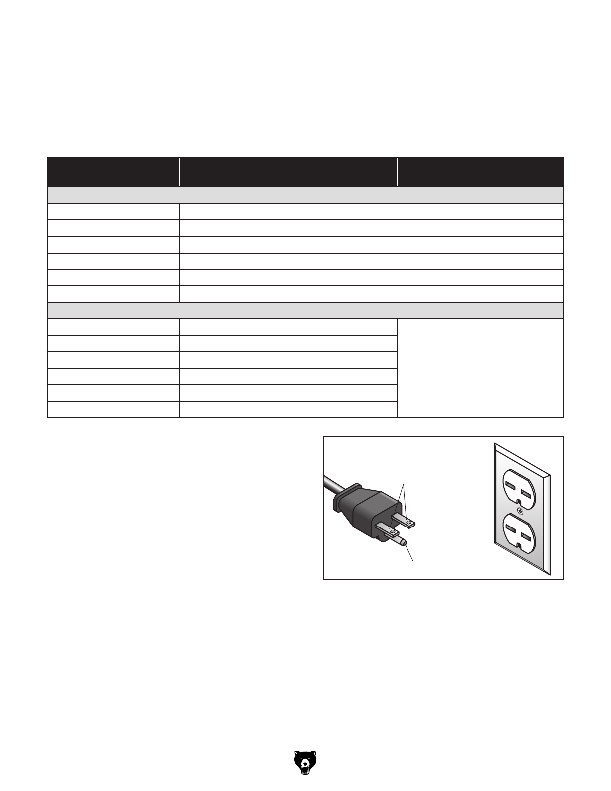
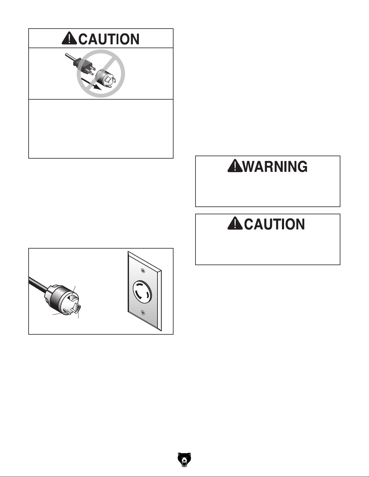
Grounding Requirements for 220V: The plug
specified under “Circuit Requirements for 220V
Operation” on this page has a grounding prong
that must be attached to the equipment-grounding
wire inside the specified power cord. The plug
must only be inserted into a matching receptacle (see Figure 5) that is properly installed and
grounded in accordance with all local codes and
ordinances.
-12-
6-15 PLUG
Grounding Prong
Figure 5. Typical 6-15 plug and receptacle.
G0513 Series Bandsaws
Page 15
No adapter should be used with the
required plug. If the plug does not fit the
available receptacle, or the machine must
be reconnected for use on a different type
For your own safety and protection of
Improper connection of the equipment-grounding
wire can result in a risk of electric shock. The
wire with green insulation (with or without yellow
stripes) is the equipment-grounding wire. If repair
or replacement of the power cord or plug is necessary, do not connect the equipment-grounding
wire to a live (current carrying) terminal.
Check with a qualified electrician or service personnel if you do not understand these grounding
requirements, or if you are in doubt about whether
the tool is properly grounded. If you ever notice
that a cord or plug is damaged or worn, disconnect it from power, and immediately replace it with
a new one.
of circuit, the reconnection must be made
by a qualified electrician and comply with all
local codes and ordinances.
Grounding Requirements for 110V: The plug
specified under “Circuit Requirements for 110V
Operation” on the previous page has a grounding
prong that must be attached to the equipmentgrounding wire inside the specified power cord.
The plug must only be inserted into a matching
receptacle (see Figure 6) that is properly installed
and grounded in accordance with all local codes
and ordinances.
L5-30 GROUNDED
LOCKING
RECEPTACLE
Neutral
L5-30
LOCKING
PLUG
Hot
Grounding Prong
is Hooked
Figure 6. Typical L5-30 plug and receptacle.
Serious injury could occur if you connect
the machine to power before completing the
setup process. DO NOT connect to power
until instructed later in this manual.
property, consult an electrician if you are
unsure about wiring practices or electrical
codes in your area.
G0513 Series Bandsaws
-13-
Page 16

Extension Cords
We do not recommend using an extension cord
with this machine.
cord, only use it if absolutely necessary and only
on a temporary basis.
Extension cords cause voltage drop, which may
damage electrical components and shorten motor
life. Voltage drop increases as the extension cord
size gets longer and the gauge size gets smaller
(higher gauge numbers indicate smaller sizes).
Any extension cord used with this machine must
contain a ground wire, match the required plug
and receptacle, and meet the following requirements:
If you must use an extension
Minimum Gauge Size at 220V .............14 AWG
Minimum Gauge Size at 110V ..............12 AWG
Maximum Length (Shorter is Better).......50 ft.
Voltage Conversion
The voltage conversion MUST be performed by
an electrician or a qualified service personnel.
Models G0513, G0513P, G0513ANV, &
G0513X2
To perform the voltage conversion, install the
correct plug and rewire the motor to the new voltage, according to the wiring diagram provided on
Page 69.
Model G0513X2F
To perform the voltage conversion, replace the
magnetic switch with the 110V version (Part No.
P0513X2F244), install the correct power cord
and plug, and rewire the motor to the new voltage, according to the wiring diagram provided on
Page 72.
If the diagram included on the motor conflicts with the one in this manual, the motor
may have changed since the manual was
printed. Use the diagram provided on the
motor.
-14-
G0513 Series Bandsaws
Page 17
SECTION 3: SETUP
Your machine was carefully packaged for safe
transportation. Remove the packaging materials
from around your machine and inspect it. If you
discover any damage, please call us immediately
at (570) 546-9663
Save the containers and all packing materials for
possible inspection by the carrier or its agent.
Otherwise, filing a freight claim can be difficult.
When you are completely satisfied with the condition of your shipment, inventory the contents.
This machine presents
serious injury hazards
to untrained users. Read
through this entire manual to become familiar with
the controls and operations before starting the
machine!
Introduction
The bandsaw is an efficient and flexible woodworking machine. However, the bandsaw functions are inter-dependent and each one must be
properly set up and adjusted so that the entire
machine operates correctly.
For instance, in this SETUP section, you will do
an initial blade tensioning before adjusting the
blade tracking. This will also allow you to properly
adjust the table angle, positive stop, blade guides,
and support bearing.
Needed for Setup
The following are needed to complete the setup
process, but are not included with your machine.
Description Qty
• Additional People ....................................... 1
• Safety Glasses .........................1 per Person
• Cleaner/Degreaser ..................... As Needed
• Disposable Shop Rags ............... As Needed
• Forklift/Strap or Chain w/Lifting Hook
(Each component rated for at least 1000 lbs)
..........................................................1 Each
• 1x4 & 2x4 Shims (Optional) ............... 1 Each
• Feeler Gauges 0.004", 0.016" ............1 Each
• Straightedge ............................................... 1
• Fine Ruler ................................................... 1
• Machinist's Square ..................................... 1
• Phillips Screwdriver #2 ............................... 1
• Hex Wrench 6mm ....................................... 1
• Dust Collection System .............................. 1
• Dust Hose 4" .............................................. 2
• Hose Clamps 4" ......................................... 2
To prepare the machine for safe cutting and good
results, take extra care when performing these
inter-dependent tasks and complete them in the
correct order.
G0513 Series Bandsaws
Unpacking
for advice.
-15-
Page 18
Inventory
The following is a description of the main components shipped with your machine. Lay the components out to inventory them.
If any non-proprietary parts are missing (e.g. a
nut or a washer), we will gladly replace them; or
for the sake of expediency, replacements can be
obtained at your local hardware store.
Keep children and pets away
from plastic bags or packing
materials shipped with this
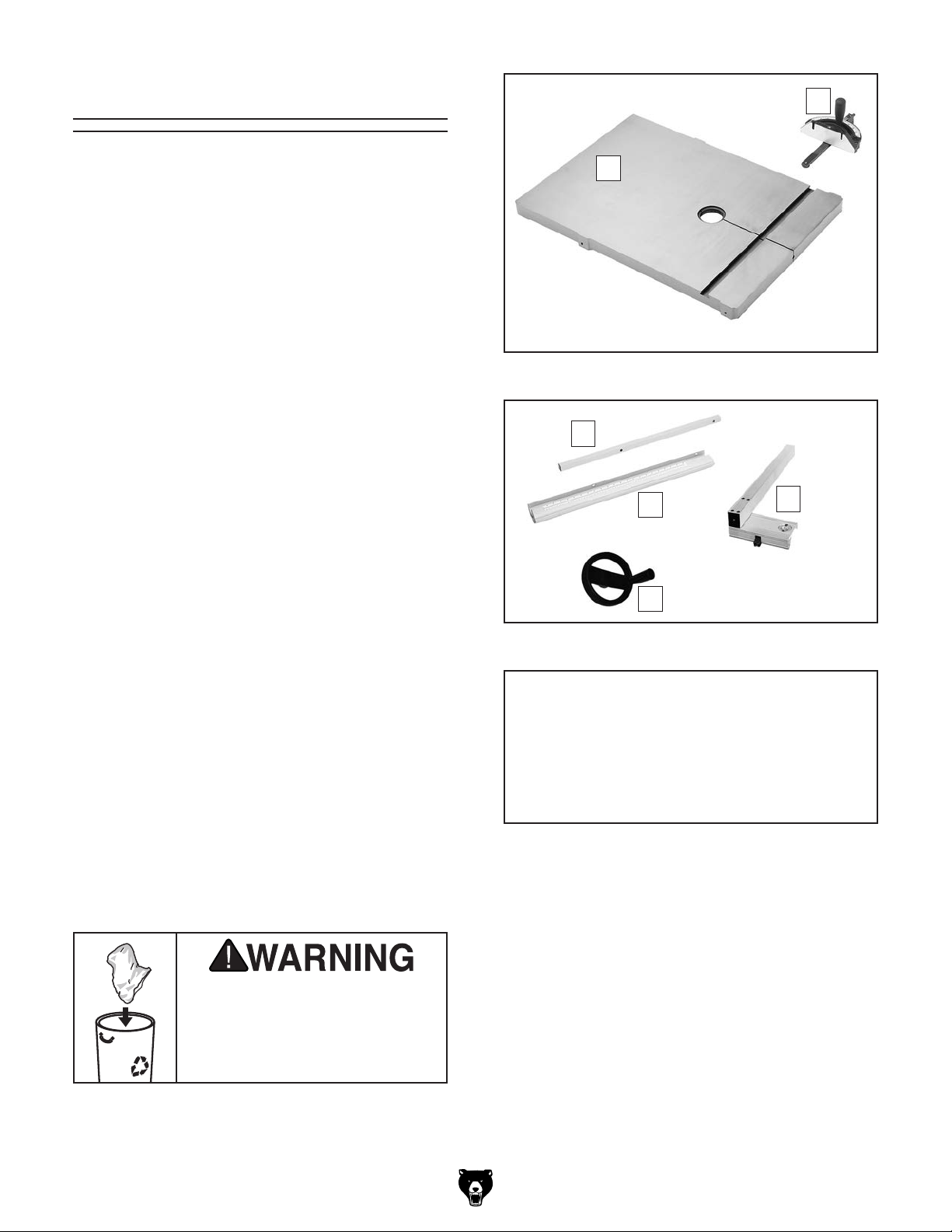
G0513, G0513P, & G0513ANV
Shipping Inventory (Figures 7 & 8): Qty
A. Bandsaw (not shown) ................................. 1
B. Table ........................................................... 1
C. Miter Gauge ................................................ 1
D. Rear Rail .................................................... 1
E. Front Rail ................................................... 1
F. Fence Assembly ......................................... 1
G. Guide Post Handwheel............................... 1
B
Figure 7. Table and miter gauge.
D
E
F
C
Hardware & Tools (Not Shown) Qty
• Eye Bolt M10-1.5 (May Be Installed) .......... 1
• Flat Washers 8mm (Table) ......................... 4
• Lock Washers 8mm (Table) ....................... 4
• Hex Bolts M8-1.25 x 16 (Table) .................. 4
• Hex Bolt M8-1.25 x 90 (Positive Stop) ........ 1
• Hex Nuts M8-1.25 (Positive Stop, Fence)... 2
• Cap Screws M6-1 x 16 (Fence) .................. 2
• Hex Bolts M6-1 x 20 (Fence) ...................... 2
• Lock Washers 6mm (Fence) ...................... 2
• Flat Washers 6mm (Fence) ........................ 2
• Hex Nut M6-1 (Fence) ................................ 1
• Table Pin..................................................... 1
• Table Insert ................................................. 1
• Fence Handle M8-1.25 x 22 (Fence) .......... 1
• Rail Pad M6-1 x 18 (Fence) ........................ 1
• Hex Wrench 5mm, 8mm.................... 1 Each
• Open End Wrench 10 x 13mm ................... 1
SUFFOCATION HAZARD!
G
Figure 8. Other bandsaw components.
NOTICE
If you cannot find an item on this list, carefully check the machine and the packaging
materials. Some of these items may be preinstalled for shipping or become misplaced
during unpacking.
-16 -
machine. Discard immediately.
G0513 Series Bandsaws
Page 19
G0513X2, G0513X2B, G0513X2BF, &
G0513X2F
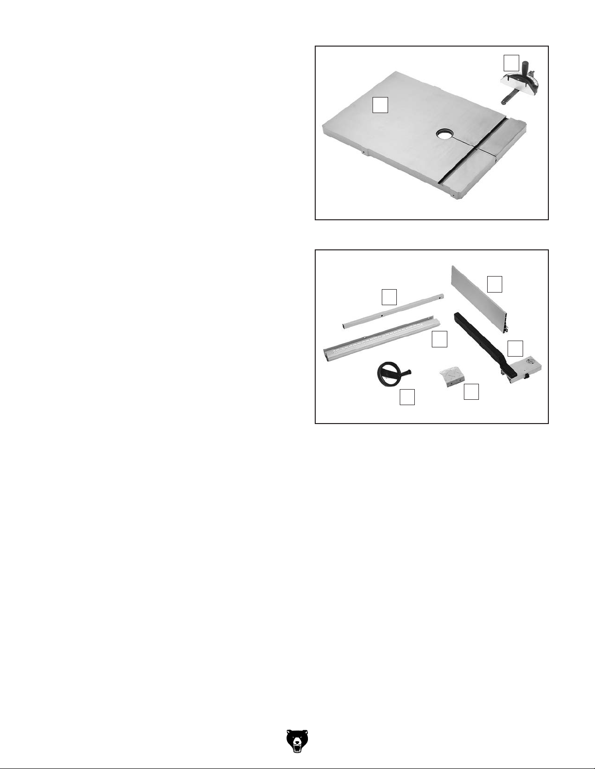
Shipping Inventory (Figures 9 & 10): Qty
A. Bandsaw (not shown) ................................. 1
B. Table ........................................................... 1
C. Miter Gauge ................................................ 1
D. Rear Rail .................................................... 1
E. Resaw Fence ............................................ 1
F. Front Rail .................................................... 1
G. Fence Assembly ......................................... 1
H. Foot Brake Pedal (G0513X2BF
& G0513X 2F) .............................................. 1
I. Guide Post Handwheel............................... 1
C
B
Hardware & Tools (Not Shown) Qty
• Eye Bolt M10-1.5 (May Be Installed) .......... 1
• Flat Washers 8mm (Table, Fence, Rail) ..... 8
• Lock Washers 8mm (Table, Rail) ............... 5
• Hex Bolts M8-1.25 x 25 (Table) .................. 4
• Hex Bolt M8-1.25 x 90 (Positive Stop) ........ 1
• Hex Nuts M8-1.25 (Positive Stop, Fence)... 2
• Cap Screws M6-1 x 20 (Rail) ..................... 3
• Cap Screw M8-1.25 x 20 (Rail) .................. 1
• Lock Washers 6mm (Rail) .......................... 3
• Flat Washers 6mm (Rail) ............................ 3
• Hex Nut M6-1 (Fence) ................................ 1
• Cap Screws M6-1 x 16 (Foot Brake Pad) ... 2
• Lock Washers 6mm (Foot Brake Pad) ....... 2
• Table Pin..................................................... 1
• Table Insert ................................................. 1
• Fence Handle M8-1.25 x 44 (Fence) .......... 1
• Rail Pad M6-1 x 18 (Fence) ........................ 1
• Moving Plate (Fence).................................. 1
• Rail Plates .................................................. 3
• Hex Wrench 5mm, 8mm.................... 1 Each
• Open End Wrench 10 x 13mm ................... 1
Figure 9. Table and miter gauge.
E
D
F
I
Figure 10. Other bandsaw components.
H
G
G0513 Series Bandsaws
-17-
Page 20
Cleanup
The unpainted surfaces of your machine are
coated with a heavy-duty rust preventative that
prevents corrosion during shipment and storage.
This rust preventative works extremely well, but it
will take a little time to clean.
Be patient and do a thorough job cleaning your
machine. The time you spend doing this now will
give you a better appreciation for the proper care
of your machine's unpainted surfaces.
There are many ways to remove this rust preventative, but the following steps work well in a wide
variety of situations. Always follow the manufacturer’s instructions with any cleaning product you
use and make sure you work in a well-ventilated
area to minimize exposure to toxic fumes.
Before cleaning, gather the following:
•
•
•
•
Basic steps for removing rust preventative:
1.
2.
amount of cleaner/degreaser, then let it soak
3. Wipe off the surfaces. If your cleaner/degreas-
off easily. If you have a plastic paint scraper,
scrape off as much as you can first, then wipe
4.
then coat all unpainted surfaces with a quality
Avoid chlorine-based solvents, such as
32"
32"
Disposable Rags
Cleaner/degreaser (WD•40 works well)
Safety glasses & disposable gloves
Plastic paint scraper (optional)
Site Considerations
Floor Load
Refer to the Machine Data Sheet for the weight
and footprint specifications of your machine.
Some residential floors may require additional
reinforcement to support both the machine and
operator.
Placement Location
Consider existing and anticipated needs, size of
material to be processed through each machine,
and space for auxiliary stands, work tables or
other machinery when establishing a location for
your new machine. See Figure 11 for the mini-
mum working clearances.
Put on safety glasses.
Coat the rust preventative with a liberal
for 5–10 minutes.
er is effective, the rust preventative will wipe
off the rest with the rag.
Repeat Steps 2–3 as necessary until clean,
metal protectant to prevent rust.
NOTICE
acetone or brake parts cleaner, that may
damage painted surfaces.
Figure 11. Minimum working clearances.
Children and visitors may be
seriously injured if unsupervised around this machine.
Lock entrances to the shop
or disable start switch or
power connection to prevent
unsupervised use.
-18-
G0513 Series Bandsaws
Page 21
Moving & Placing
Bandsaw
This bandsaw is a heavy
machine. Serious personal
injury may occur if safe
moving methods are not
used. Get assistance and
use power equipment to
move the shipping crate
and remove the machine
from the shipping pallet.
Special care should be taken when moving this
bandsaw. Only use one of the following methods
to lift or move this bandsaw.
Using Wood Blocks
1. Move the crate to the prepared location, then
remove the crate from the shipping pallet.
2. Unbolt the bandsaw from the pallet.
3. Carefully place the forklift forks under the
head and insert a 1x4 block between the head
and the left fork and a 2x4 block between the
head and right fork so the bandsaw is level,
as shown in Figure 13.
2x4
1x4
Using Eye Bolt
1. Move the crate to the prepared location, then
remove the crate from the shipping pallet.
2. Unbolt the bandsaw from the pallet.
3. Install the eye bolt shown (see Figure 12),
make sure it is threaded all the way in, then
place the lifting hook through the eye bolt and
lift the bandsaw slowly with a forklift.
Eye Bolt
Figure 13. Example photo of lifting bandsaw with
forklift using wood shims.
4. Lift the bandsaw off of the pallet, remove the
pallet, then slowly set the bandsaw into position.
Note: If you are concerned about your forklift
forks hitting the tension handwheel, remove the
handwheel before positioning the forks, then reinstall it after placing.
Serious injury could occur if you connect
the machine to power before completing the
setup process. DO NOT connect to power
until instructed later in this manual.
Figure 12. Lifting the bandsaw.
4. Remove the pallet and slowly set the bandsaw
into position.
G0513 Series Bandsaws
-19 -
Page 22
Mounting
Assembly
We recommend mounting your new machine to
the floor. Because floor materials may vary, floor
mounting hardware is not included. You may also
mount your machine to a mobile base that has
wheel locking or wheel retracting capabilities that
keeps the mobile base from rolling when not in
use.
Bolting to Concrete Floors
Lag shield anchors with lag bolts (see Figure 14)
and anchor studs (see Figure 15) are two popular
methods for anchoring an object to a concrete
floor. We suggest you research the many options
and methods for mounting your machine and
choose the best that fits your specific application.
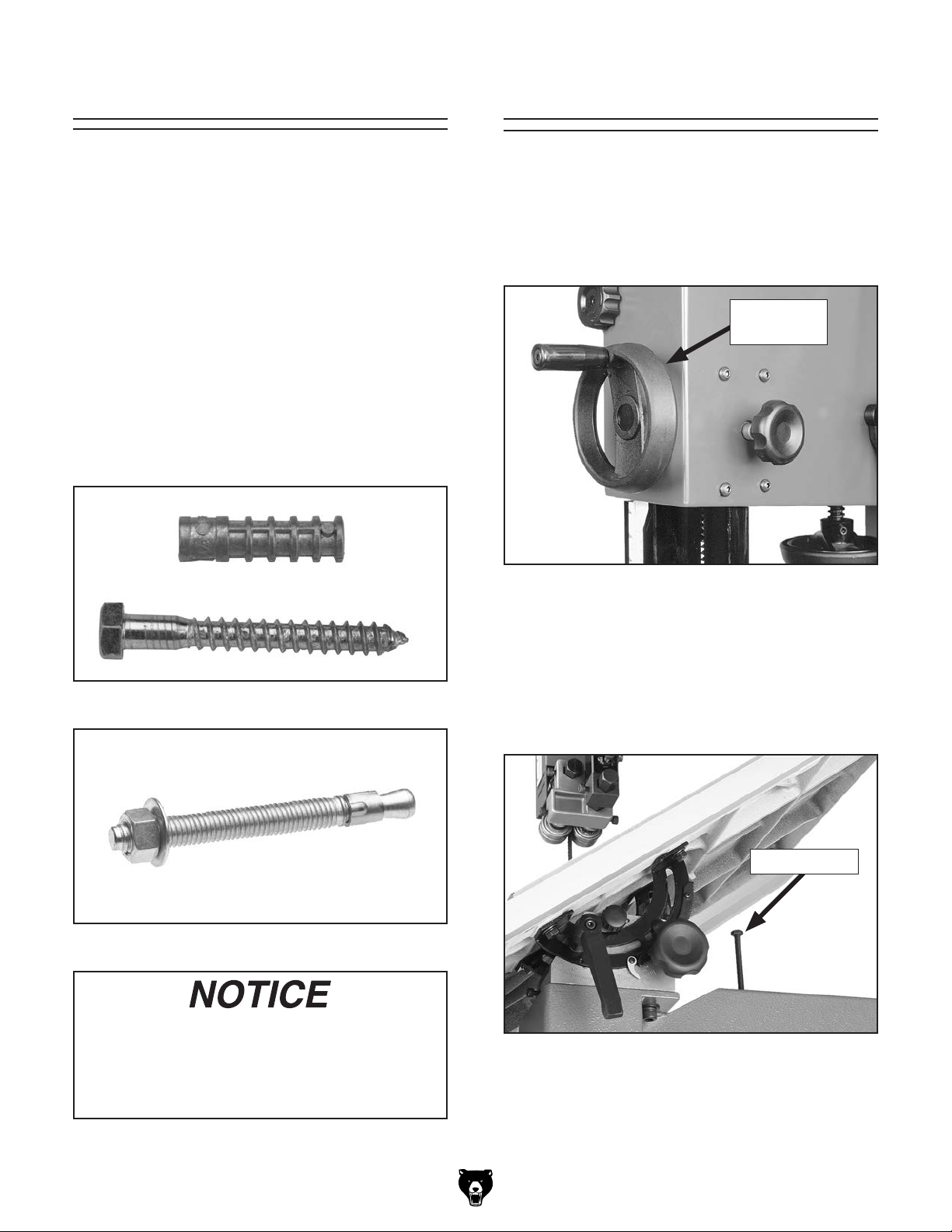
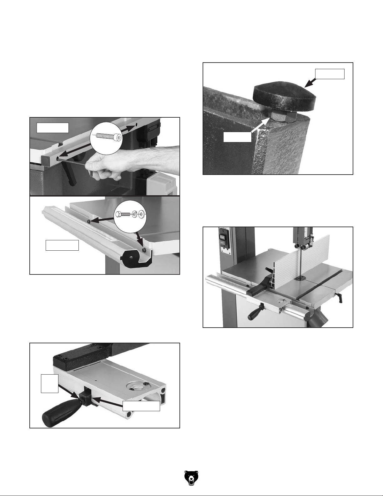
Installing Guide Post Handwheel,
Positive Stop Bolt, & Table
1. Secure the guide post handwheel onto the
handwheel shaft flat with the included set
screw (see Figure 16).
Guide Post
Handwheel
Figure 16. Guide post handwheel installed.
Figure 14. Typical lag shield anchor and bolt.
Figure 15. Typical anchor stud.
Anchor studs are stronger and more permanent alternatives to lag shield anchors;
however, they will stick out of the floor,
which may cause a tripping hazard if you
decide to move your machine.
2. Thread the M8-1.25 hex nut halfway onto the
M8-1.25 x 90 hex bolt (this is the positive stop
bolt).
3. Thread the positive stop bolt into the threaded hole on bandsaw body (see Figure 17).
Positive Stop
Figure 17. Positive stop bolt installed.
-20-
G0513 Series Bandsaws
Page 23
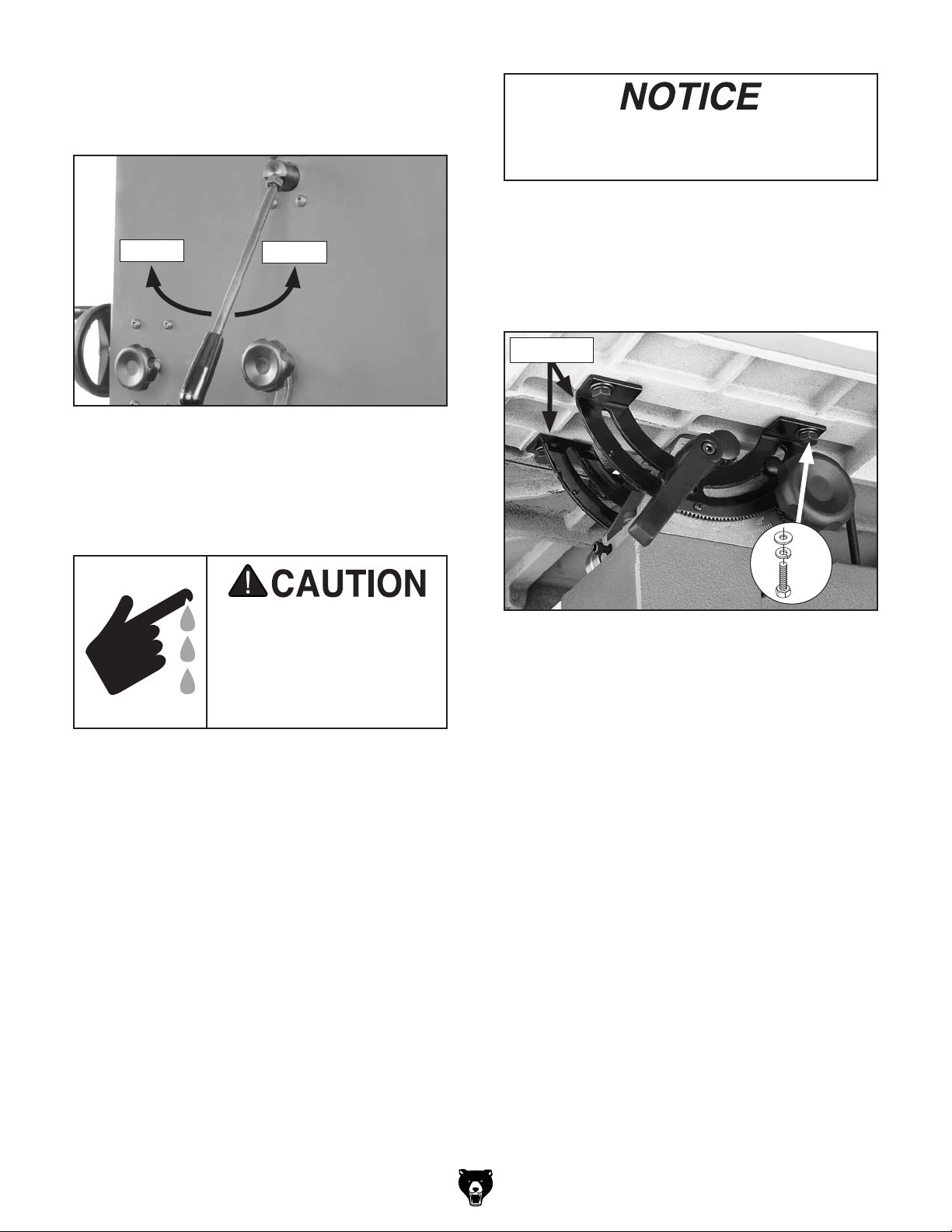
4. Loosen blade tension by rotating the quick-
release tension lever clockwise, as shown in
Figure 18.
Loosen
Figure 18. Quick-release tension lever.
5. Adjust the upper and lower blade guides
away from the blade. Refer to Adjusting
Blade Guides beginning on Page 33 for
more details.
Tighten
The table is heavy and requires two people
to lift it onto the trunnions. Remove the saw
blade to make table installation easier.
8. Models G0513, G0513P and G0513ANV:
Secure the table to the trunnions, as shown
in Figure 19 with the (4) M8-1.25 x 16 hex
bolts, 8mm lock washers, and 8mm flat washers.
Trunnions
All saw blades are dangerous and may cause personal injury. To reduce the
risk of being injured, wear
leather gloves when handling saw blades.
6. Remove the saw blade (refer to Blade
Changes on Page 48 for detailed instruc-
tions).
7. With the help of another person, lift the table
onto the trunnions.
x 4
Figure 19. Mounting the table.
Models G0513X2, G0513X2B, G0513X2BF,
and G0513X2F: Secure the table to the trun-
nions with the (4) M8-1.25 x 25 hex bolts,
8mm lock washers, and 8mm flat washers.
9. Replace the saw blade.
G0513 Series Bandsaws
-21-
Page 24
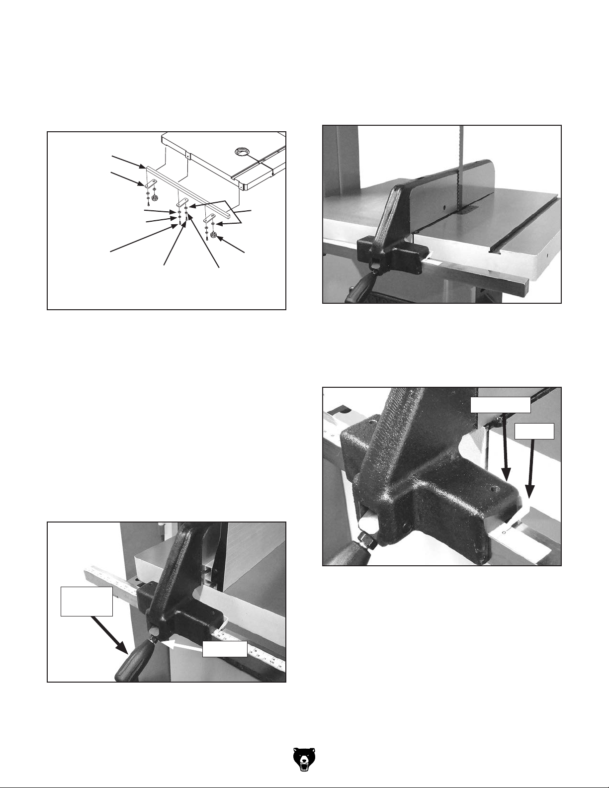
Installing Fence (G0513, G0513P,
G0513ANV, G0513X2, & G0513X2F)
1. Attach the rear rail to the table with the
(2) M6-1 x 16 cap screws, as shown in
Figure 20.
2. Attach the front rail with the (2) M6-1 x 20 hex
bolts, 6mm lock washers, and 6mm flat washers, as shown in Figure 20.
Rear Rail
x 2
4. Thread the M6-1 hex nut onto the rail pad,
then thread the rail pad into the rear of the
fence (see Figure 22).
Rail Pad
Hex Nut
Figure 22. Installed rail pad.
5. Pull the fence handle up and place the fence
assembly on the front rail (see Figure 23 for
an example photo).
x 2
Front Rail
Figure 20. Rail installation.
3. Install an M8-1.25 hex nut on the fence
handle, then thread the handle into the fence
assembly, as shown in Figure 21. Tighten
the hex nut against the fence pivot block to
secure the handle.
Hex
Nut
Pivot Block
Figure 23. Example photo of correctly installed
fence.
6. Push the fence handle down to lock the fence
assembly in place.
7. Adjust the rear rail pad until there is an even
gap between the bottom of the fence and the
table, then tighten the rail pad hex nut against
the fence.
Figure 21. Handle installed on fence assembly.
-22-
G0513 Series Bandsaws
Page 25
Installing Fence (G0513X2B &
G0513X2BF)
1. Attach the rail plates to the front rail with the
(3) M6-1 x 20 cap screws, 6mm lock washers, and 6mm flat washers (see Figure 24).
Front Rail
Rail Plate
5. Install the fence on the left-hand side of the
blade.
6. Place the fence flush against the bandsaw
blade (see Figure 26).
Flat Washer 6mm
Lock Washer 6mm
Cap Screw
M6-1 x 20
Cap Screw
M8-1.25 x 20
Figure 24. Installing front rail onto table.
2. Attach the outer two rail plates with the round
and elongated mounting holes to the outer
part of the table bottom with (2) M8-1.25 x 20
knobs and 8mm flat washers.
3. Attach the remaining rail plate with the round
mounting holes using (1) M8-1.25 x 20 cap
screw, 8mm lock washer, and 8mm flat
washer (see Figure 24).
4. Thread the fence handle into the fence, then
tighten the hex nut against the fence pivot
block (see Figure 25).
Lock Washer
8mm
Flat
Washer
8mm
Knob
Figure 26. Fence flush with blade.
7. Loosen the pointer adjustment nut (see
Figure 27) and set the pointer in line with "0"
on the measurement scale on the rail.
Pointer Nut
Pointer
Fence
Handle
Figure 25. Fence handle components.
G0513 Series Bandsaws
Figure 27. Calibrating fence pointer
(adjustment nut out of view).
8. Re-tighten the pointer adjustment nut.
Hex Nut
-23-
Page 26
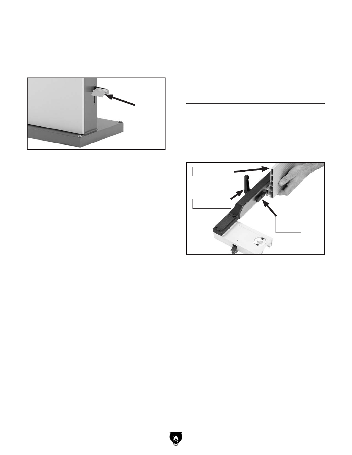
Installing Foot Brake Pedal
(G0513X2BF & G0513X2F)
Secure the foot brake pedal to the brake lever
using the (2) M6-1 x 16 cap screws and 6mm lock
washers, as shown in Figure 28.
Brake
Pedal
Figure 28. Foot brake installed.
Installing Resaw
Fence (G0513X2,
G0513X2B,
G0513X2BF, &
G0513X2F)
To Install the resaw fence:
1. Place the 8mm flat washer on the lock handle
(see Figure 29), slide it through the hole in
the fence, then thread the moving plate onto
the end of the lock handle threads.
Resaw Fence
Lock Handle
Moving
Plate
Figure 29. Attaching resaw fence.
2. Slide the resaw fence over the moving plate,
as shown in Figure 29, so the moving plate
fits inside the channel of the resaw fence,
then tighten the lock handle.
-24-
G0513 Series Bandsaws
Page 27
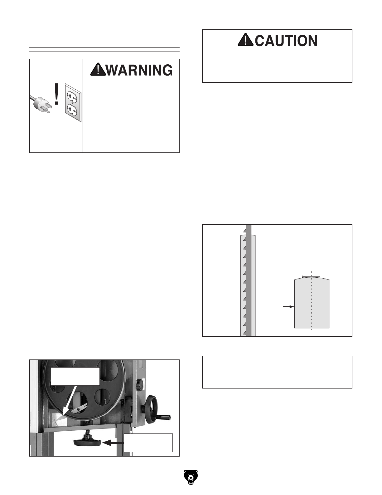
Initial Blade Tracking
Blade Centered
on Peak of Crown
Blade
Centered
on
Wheel
Wheel
Serious personal injury can
occur if the machine starts
while your hand is touching the bandsaw wheel during tracking adjustments.
Disconnect power from the
bandsaw before performing blade tracking adjustments.
Blade tracking is primarily affected by the tilt of
the upper wheel, known as “center tracking.”
However, the alignment of both wheels plays an
important part as well (see the Aligning Wheels
instructions on Page 65 for more details).
The wheels on this bandsaw were aligned at the
factory, so center tracking is the only adjustment
that needs to be performed when the saw is
new.
The wheels may have sharp edges and the
blade teeth may extend beyond the edge,
creating a laceration hazard. Be careful
when turning the wheels by hand.
5. Spin the upper wheel by hand at least three
times and watch how the blade rides on the
crown of the wheel. Refer to Figure 31 for an
illustration of this concept.
— If the blade rides in the center of the upper
wheel and is centered on the peak of the
wheel crown, then the bandsaw is already
tracking properly and no further adjustments are needed at this time.
— If the blade does not ride in the center of
the upper wheel and is not centered on the
peak of the wheel crown, then continue
with the following steps.
To center track the blade:
1. DISCONNECT BANDSAW FROM POWER!
2. Make sure the upper and lower blade guides
are adjusted away from the blade.
3. Open the upper wheel cover.
4. Engage the quick tension lever, then turn the
blade tension handwheel until the tension
scale (see Figure 30) is between 4 and 6.
Blade Tension
Scale
Blade Tension
Handwheel
Figure 30. Blade tensioning controls.
Figure 31. Center tracking profiles.
IMPORTANT
Changes made to the blade tension may
change how the blade tracks.
G0513 Series Bandsaws
-25-
Page 28
6. Loosen the lock lever on the back of the
bandsaw (see Figure 32) so that the blade
tracking knob can rotate.
Blade Tracking
Knob
Lock Lever
Figure 32. Blade tracking controls.
Adjusting Positive
Stop
The positive stop allows the table to be quickly
and accurately returned to the horizontal (0˚) position after being adjusted to a different angle.
To position the positive stop:
1. DISCONNECT BANDSAW FROM POWER!
2. Adjust the blade tension until the mark on the
blade tension scale is between 4 and 6.
3. Loosen the hex nut that locks the positive
stop bolt in place.
7. Spin the upper wheel with one hand and
rotate the tracking control knob in small
amounts with the other hand until the blade
consistently rides in the center of the bandsaw
wheel tire.
8. Tighten the tracking control lock knob and
close the upper wheel cover.
Note: For the best performance from your saw,
regularly maintain proper tracking of the blade.
Fine tune tracking must be done with the bandsaw
turned ON. This will be explained later in the
Operations section.
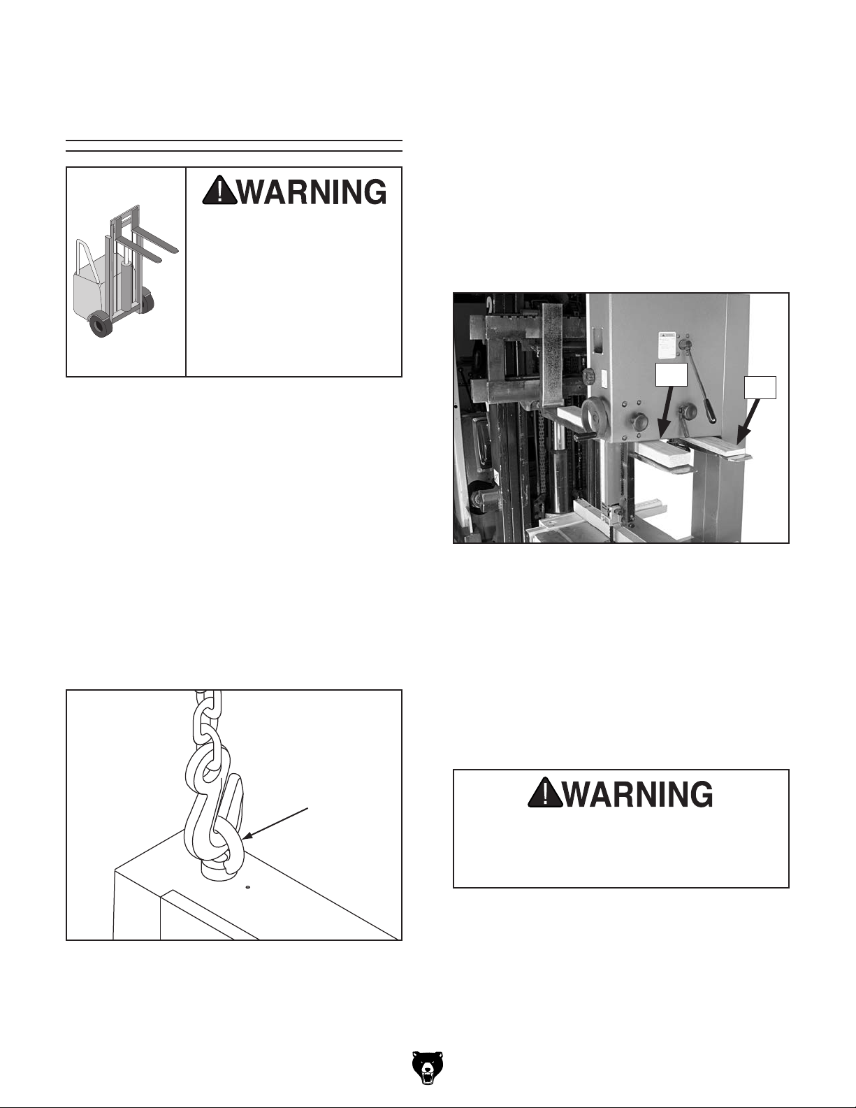
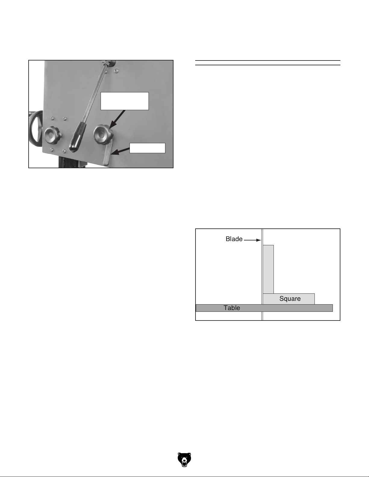
4. Raise the guide post and place a machinist’s
square on the table next to the side of the
blade, as illustrated in Figure 33. Adjust the
table square with the blade, then secure it
with the table tilt lock lever.
Figure 33. Squaring table to blade.
5. Adjust the positive stop bolt against the bot-
tom of the table and secure it by tightening
the hex nut against the trunnion bracket.
-26-
6. Check the adjustment for accuracy once you
have tightened the hex nut.
7. Loosen the screw on the pointer, but do not
remove it.
8. Align the tip of the pointer with the 0˚ mark on
the table tilt scale, then re-tighten the screw
to secure the setting.
G0513 Series Bandsaws
Page 29
Dust Collection
Power Cord
Connection
(G0513X2BF &
DO NOT operate this bandsaw without an
adequate dust collection system. This saw
creates substantial amounts of wood dust
while operating. Failure to use a dust collection system can result in short and longterm respiratory illness.
Recommended CFM at Dust Port: 400 CFM
Do not confuse this CFM recommendation with
the rating of the dust collector. To determine the
CFM at the dust port, you must consider these
variables: (1) CFM rating of the dust collector,
(2) hose type and length between the dust collector and the machine, (3) number of branches
or wyes, and (4) amount of other open lines
throughout the system. Explaining how to calculate these variables is beyond the scope of
this manual. Consult an expert or purchase a
good dust collection "how-to" book.
To connect a dust collection hose:
G0513X2F)
Serious injury could occur if you connect
the machine to power before completing the
setup process. DO NOT connect to power
until instructed later in this manual.
The power cord connection MUST be performed
by an electrician or qualified service personnel.
Items Needed Qty
Cord “ S ”-Type , 3-Wire, 14 AWG, 300 VAC,
at least 6 ft. long ......................................... 1
Phillips Screwdriver #2 ...................................... 1
Wire Nuts for (2) 14 AWG Wires ........................ 3
Electrical Tape ................................... As Needed
To connect the power cord to the machine:
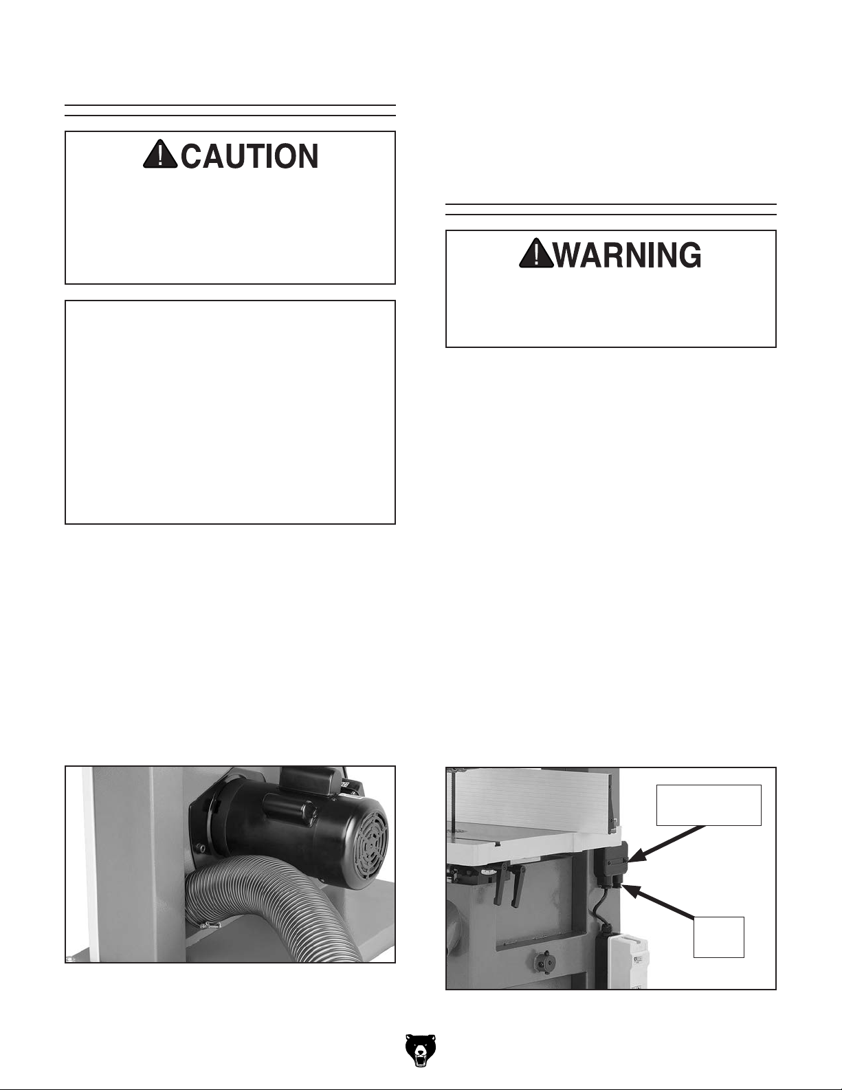
1. Fit a 4" dust hose over each dust port and
secure them in place with a hose clamp (see
Figure 34).
2. Tug the hoses to make sure they do not
come off.
Note: A tight fit is necessary for proper per-
formance.
Figure 34. Dust hose attached to bottom dust
port.
1. Attach the required plug to the cord per
the plug manufacturer's instructions (refer
to Power Supply beginning on Page 11 for
specifications and the NEMA plug wiring on
Pages 71– 72).
2. Remove the power supply junction box cover
from the right rear of the bandsaw (see
Figure 35). It is secured by two screws.
Power Supply
Junction Box
Strain
Relief
Figure 35. Power supply junction box on rear of
bandsaw.
G0513 Series Bandsaws
-27-
Page 30
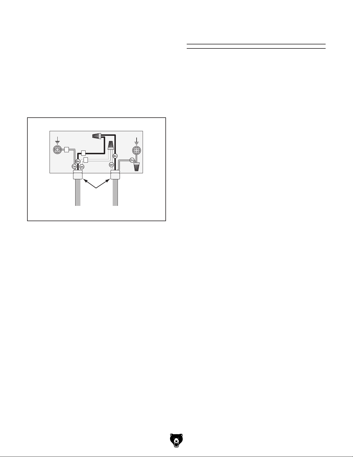
3. Loosen the right strain relief on the junction
box, then feed the cord into the box with
enough slack in the wires to make the connections.
4. Re-tighten the strain relief around the cord.
Tug on it to make sure the wires inside the
box will not move.
5. Connect the incoming ground wire to the
ground post, as shown in Figure 36.
Power Supply Junction Box
Ground
E
R
S
Ground
Test Run
Once the assembly is complete, test run your
machine to make sure it runs properly and is
ready for regular operation.
The test run consists of verifying the following: 1)
The motor powers up and runs correctly, and 2)
the safety disabling mechanism works correctly.
If, during the test run, you cannot easily locate
the source of an unusual noise or vibration, stop
using the machine immediately, then review
Troubleshooting on Page 57.
If you still cannot remedy a problem, contact our
Tech Support at (570) 546-9663 for assistance.
To test run the machine:
Strain
Relief
To
Bandsaw
From
Power Supply
Figure 36. Incoming power cord connections.
6. Secure the two incoming hot wires to the
black and white wires from the bandsaw
with wire nuts, then wrap the nuts and wires
with electrical tape to make sure they will not
come loose.
7. Re-attach the junction box cover.
1. Make sure that you have successfully com-
pleted the Initial Blade Tracking procedure
on Page 25 before continuing.
2. Make sure you have read the safety instruc-
tions at the beginning of the manual and that
the machine is setup properly.
3. Make sure all tools and objects used during
setup are cleared away from the machine.
4. Connect the machine to the power source.
5. Test the operation of the machine to verify
that it starts and operates correctly.
G0513, G0513P, G0513ANV, & G0513X2
Only
a. Verify that the machine is operating cor-
rectly by pressing the power button.
— When operating correctly, the
machine runs smoothly with little or
no vibration or rubbing noises.
-28-
— Investigate and correct strange or
unusual noises or vibrations before
operating the machine further. Always
disconnect the machine from power
when investigating or correcting
potential problems.
G0513 Series Bandsaws
Page 31

G0513X2B, G0513X2F, & G0513X2BF Only
a. Insert the key into the power switch (see
Figure 37), then turn it to the "1".
Power Switch
ON Button
OFF Button
e. Push the OFF button in, then twist it
clockwise so it pops out. When the OFF
button pops out, the switch is reset and
ready for operation (see Figure 38).
OFF Button
Figure 38. Resetting the OFF button.
f. Turn the key in the power switch to "0".
Figure 37. G0513X2B and G0513X2BF control
panel.
b. Verify that the machine is operating cor-
rectly by pressing the ON button.
— When operating correctly, the
machine runs smoothly with little or
no vibration or rubbing noises.
— Investigate and correct strange or
unusual noises or vibrations before
operating the machine further. Always
disconnect the machine from power
when investigating or correcting
potential problems.
c. Press the OFF button to stop the
bandsaw.
d. WITHOUT resetting the OFF button, press
the ON button. The machine should not
start.
— If the machine does start (with the
OFF button pushed in), immediately
disconnect the machine from power.
The OFF button safety feature is not
working correctly. This safety feature
must work properly before proceeding with regular operations. Call Tech
Support for help.
g. Try to turn the machine ON. The bandsaw
should not start.
— If the bandsaw starts, immediately
disconnect the machine from power.
The switch disabling feature is not
working correctly. This safety feature
must work properly before proceeding with regular operations. Call Tech
Support for help.
6. Test the operation of the foot brake:
G0513X2BF & G0513X2F Only
a. Start the bandsaw, then press the foot
brake. The motor should shut off and the
blade should come to a rapid stop.
— If the motor does not stop or the
blade does not come to a rapid stop,
immediately disconnect the machine
from power. The foot brake feature
is not working correctly. This safety
feature must work properly before
proceeding with regular operations.
Call Tech Support for help.
Congratulations! The test run is complete and you
are ready to proceed with the following adjustments before putting the bandsaw into full operation.
G0513 Series Bandsaws
-29-
Page 32

Tensioning Blade
A properly tensioned blade is essential for making accurate cuts, maximizing the life of the
blade, and making other bandsaw adjustments.
However, it will not compensate for cutting problems caused by too rapid of a feed rate, hardness
variations between workpieces, and improper
blade selection.
Improper blade tension is unsafe, produces
inaccurate and inconsistent results, and
introduces unnecessary wear on bandsaw
components. Over-tensioning the blade
increases the chance of the blade breaking
or wheel misalignment. Under-tensioned
blades wander excessively while cutting
and will not track properly during operation.
4. Engage the blade tension quick-release
lever to apply tension to the blade (see
Figure 39).
Blade Tension
Quick-release
Lever
Figure 39. Blade tension quick-release lever
(G0513X2 shown).
5. Connect the bandsaw to power, and turn the
bandsaw ON.
6. Using the blade tension handwheel
(Figure 40), slowly decrease blade tension
until the blade starts to flutter.
Tensioning the blade according to the blade
tension scale before the Test Run section
gave an approximate tension for completing
the bandsaw setup. The following procedures tension the blade for operation.
Blade tensioning method is a matter of preference.
The flutter method and the deflection method are
described below. Either method safely tensions
the blade. Experience and personal preference
will help you decide which method your prefer.
Optimal cutting results for any workpiece results
from a combination of correct blade selection,
proper blade tension, and a light and even feed
rate.
Flutter Method
1. DISCONNECT BANDSAW FROM POWER!
2. Make sure the blade is properly center track-
ing as instructed in the Initial Blade Tracking
on Page 25.
Blade Tension
Handwheel
Figure 40. Blade tension handwheel.
7. Slowly increase the tension until the blade
stops fluttering, then turn the blade tension
adjustment knob an additional
turn.
8. Turn the bandsaw OFF and disconnect it
from power.
9. Note what the tension gauge reads. Use that
as a guide for tensioning that specific blade
in the future.
1
⁄8 to 1⁄4 of a
3. Raise the guide post all the way, and move
the upper and lower blade guides away from
the blade.
-30-
10. Re-adjust blade guides as described in
Adjusting Blade Guides beginning on Page
33 for your model bandsaw.
G0513 Series Bandsaws
Page 33

Deflection Method
The deflection method is more subjective than the
flutter method. Each blade deflects differently and
every user must determine what "moderate pressure" means. The following are general guidelines for tensioning the blade with the deflection
method.
To tension the bandsaw blade:
5. Using moderate pressure, push the center of
the blade sideways.
1
— If the blade deflects approximately
⁄4", it is
properly tensioned. Proceed to Step 6.
1
— If the blade deflects less than
⁄4" it is
over-tensioned. Turn the blade tensioning
handwheel counterclockwise two full turns
and repeat this step.
1. DISCONNECT BANDSAW FROM POWER!
2. Make sure the blade is properly tracking as
instructed in the Initial Blade Tracking section on Page 25.
3. Raise the guide post all the way, and move
the upper and lower blade guides away from
the blade.
4. Engage the blade tension quick-release lever
to apply tension to the blade.
1
— If the blade deflects more than
⁄4", the
blade is under-tensioned. Apply tension to
the blade a small amount and repeat this
step until the blade is properly tensioned.
6. Re-adjust the blade guides as described in
Adjusting Blade Guides beginning on Page
33 for your model bandsaw.
Whenever changing a blade or adjusting
tension and tracking, the upper and lower
blade support bearings and blade guides
must be properly adjusted before performing cutting operations.
G0513 Series Bandsaws
-31-
Page 34

Adjusting Blade
Support Bearings
Tools Needed Qty
Hex Wrench 5mm .............................................. 1
Feeler Gauge 0.016" ................................. 1 Each
Crisp Dollar Bill (Optional) ................................. 1
Support bearings stop excessive backward deflection of the blade from the advancing workpiece.
The proper adjustment of the support bearings
is an important part of making accurate cuts and
prevents damage to the blade teeth from contact
with the blade guides.
It is important that the distance of the support
bearing behind the blade is the same as the distance of the blade guides behind the teeth gullets,
which is typically about 0.016" (see Figure 41).
0.016"
Gap
0.016"
Gap
Support
Bearing
Tip: You can use a crisp dollar bill in place of the
feeler gauge for the following procedures. The
thickness of the bill when folded in half twice is
approximately 0.016".
Refer to Figures 42–43 and the following descrip-
tions to become familiar with the controls to adjust
the support bearings. Then, adjust the surface of
the support bearings approximately 0.016" behind
the blade.
Note: The support bearing controls are similar for
all models.
A
B
Blade
Guide
Figure 41. Distance settings of upper support
bearings and blade guides.
Before adjusting the blade support bearings, make sure the blade is tracking properly (Page 25) and that it is correctly tensioned (Page 30).
C
Figure 42. Upper support bearing controls.
D
A
Figure 43. Lower support bearing controls.
C
-32-
G0513 Series Bandsaws
Page 35

A. Support Bearing. Stops excessive back-
ward blade deflection from the pressure of
the advancing workpiece.
Note: The flat surface of the upper support
bearing faces the blade. The round edge of
the lower support bearing faces the blade.
B. Upper Support Bearing Shaft. Mounts the
support bearing behind the blade. When the
support bearing shaft cap screw is loose,
move this shaft by hand to adjust the upper
support bearing approximately 0.016" behind
the blade, then re-tighten the shaft cap screw
to secure the setting.
Adjusting Blade
Guides
The blade guides provide side-to-side support
to keep the blade straight while cutting. These
guides are adjustable in two ways—forward-andback and side-to-side.
To keep the blade straight while cutting, the blade
guides must be as close to the sides of the blade
without exerting any clamping pressure. This distance is typically about 0.004".
C. Support Bearing Shaft Cap Screw. When
loose, allows distance adjustment of the support bearing behind the blade.
D. Lower Support Bearing Adjustment Knob.
When the support bearing shaft cap screw is
loose, moves the support bearing toward or
away from the blade. Use this knob to adjust
the lower support bearing approximately
0.016" behind the blade, then re-tighten the
shaft cap screw to secure the setting.
To prevent damage to the blade teeth as the blade
deflects back while cutting, the guides must be
behind the teeth gullets the same amount as the
support bearing is behind the blade, which is typically about 0.016" (see Figure 41 on the previous
page for an illustration of this relationship).
Note: Models G0513, G0513P, and G0513ANV
use carbide discs as guides, while the remaining
models use ball bearings.
Before adjusting the blade guides, make
sure the blade is tracking properly (Page 25)
and that it is correctly tensioned (Page 30).
Important: Although the function and the distance
adjustment of the blade guides is the same for all
the G0513 Series Models, the guide controls are
not all the same. Use the set of instructions on
the following pages that is correct for your model
of bandsaw.
G0513 Series Bandsaws
-33-
Page 36

Adjusting Blade Guides (G0513,
G0513P, & G0513ANV)
Tools Needed Qty
Hex Wrench 5mm .............................................. 1
Feeler Gauge 0.004" ................................ 1 Each
Crisp Dollar Bill (Optional) ................................. 1
Fine Ruler .......................................................... 1
Tip: You can use a crisp dollar bill in place of the
feeler gauge. The thickness of the bill is approximately 0.004" .
To adjust the upper blade guides:
1. DISCONNECT BANDSAW FROM POWER!
2. Loosen the thumb screws shown in
Figure 44.
3. By hand, adjust the distance of the guides
approximately 0.004" from the sides of the
blades (see Figure 45), then re-tighten the
thumb screws to secure the setting.
0.004"
Gap
Blade
Guides
Blade
Figure 45. Correct gap between guide guides
and blade.
Blade
Guides
Thumb
Screws
Figure 44. Upper blade guides side-to-side con-
trols.
4. Loosen the guide block cap screw shown in
Figure 46.
Guide
Block
Figure 46. Back of upper blade guides.
Guide Block
Cap Screw
-34-
G0513 Series Bandsaws
Page 37

Blade
Guides
0.004"
Gap
Blade
5. By hand, slide the guide block to position the
blade guides approximately 0.016" behind
the teeth gullets (see Figure 47), then retighten the guide block cap screw to secure
the setting.
Blade
0.016"
Gap
Tooth
Gullet
Guide
Adjusting Blade Guide Bearings
(G0513X2, G0513X2B, G0513X2BF, &
G0513X2F)
Tools Needed Qty
Hex Wrench 5mm .............................................. 1
Feeler Gauge 0.004", 0.016" ....................1 Each
Crisp Dollar Bill (Optional) ................................. 1
Tip: You can use a crisp dollar bill in place of the
feeler gauge. The thickness of the bill is approximately 0.004", and when folded in half twice is
approximately 0.016".
Note: The upper and lower guide bearings are
adjusted in the same manner.
To adjust the upper and lower blade guide
bearings:
Figure 47. Correct guide alignment behind the
teeth gullets.
Make sure that the blade teeth will not contact the guides when the blade is against the
rear support bearing during the cut or the
blade teeth will be damaged.
The lower blade guides are adjusted in the same
manner as the upper blade guides. However,
some controls are different. Refer to Figure 48 to
become familiar with these controls.
Thumb
Screw
1. DISCONNECT BANDSAW FROM POWER!
2. Familiarize yourself with the blade guide con-
trols shown in Figure 49.
Blade Guide
Bearings
Knurled
Knob
Figure 49. Blade guide controls.
Lateral Rod
Cap Screw
Bearing Rotation
Cap Screw
Guide
Block
Figure 48. Lower blade guide controls.
G0513 Series Bandsaws
Guide Block
Cap Screw
Make sure that the blade teeth will not contact the guide bearings when the blade is
against the rear support bearing during the
cut or the blade teeth will be damaged.
-35-
Page 38

3. Loosen the lateral rod cap screw and slide
Blade
Gullet
Guide
Bearings
0.016"
Gap
the guide block to position the blade guides
approximately 0.016" behind the blade gullets, as illustrated in Figure 50.
Note: The 0.016" spacing is ideal, although
with larger blades it may not be possible.
In such cases, adjust the guide bearings as
far forward as possible to the blade gullets,
and still maintain the proper support bearing
spacing adjustment.
Aligning Table
To ensure cutting accuracy when the table is first
installed, the table should be aligned so that the
miter slot is parallel to the bandsaw blade. This
procedure works best with a wide (
installed.
Tools Needed Qty
Straightedge ...................................................... 1
Fine Ruler .......................................................... 1
Square ............................................................... 1
Wrench or Socket 13mm ................................... 1
To align the table so the miter slot is parallel
to the bandsaw blade:
1. Make sure that the blade is tracking properly
and that it is correctly tensioned.
2. DISCONNECT BANDSAW FROM POWER!
3
⁄4") blade
Figure 50. Lateral adjustment of blade guides.
4. Tighten the lateral rod cap screw to secure
the setting.
5. Loosen both bearing rotation cap screws.
6. Rotate the knurled knob to position the bear-
ings approximately 0.004" away from the
blade.
7. Re-tighten the cap screws to lock the blade
guide bearings in position.
3. Loosen the trunnion bolts that secure the
table.
4. Place an accurate straightedge along the
blade. The straightedge should lightly touch
both the front and back of the blade.
Note: Make sure the straightedge does not
go across a tooth.
5. Use a fine ruler to gauge the distance
between the straightedge and the miter slot.
The distance you measure should be the
same at the front and the back of the table
(see Figure 51).
-36-
Figure 51. Measuring for miter slot to be parallel
with blade.
G0513 Series Bandsaws
Page 39

— If the distance is not the same at the front
and back of the table, adjust the table until
it is.
4. Loosen the four cap screws located on the
top face of the fence (see Figures 53–54).
6. Place a square on the table and against the
back of the blade, as shown in Figure 52.
The table should be perpendicular to the
back of the blade.
— If the table is not perpendicular to the back
of the blade, shim the table in the desired
direction by placing washers between the
table and the two trunnions.
7. Re-tighten the trunnion bolts to secure the
settings.
Blade
Square
Table
G0513, G0513P, & G0513ANV
Fence Cap Screws
Figure 53. G0513, G0513P, & G0513ANV fence
caps screws.
G0513X2F Fence
Cap Screws
Figure 52. Squaring back of blade and table.
Aligning Fence
To ensure cutting accuracy when the fence is first
installed, the fence should be aligned with the
miter slot.
Tool Needed Qty
Hex Wrench 5mm .............................................. 1
Aligning Fence (G0513, G0513P,
G0513ANV, G0513X2, & G0513X2F)
1. DISCONNECT BANDSAW FROM POWER!
2. Make sure the table is aligned with the blade
(see Aligning Table on the previous page for
detailed instructions).
Figure 54. Four fence cap screws.
5. Adjust the fence face parallel with the edge of
the miter slot.
6. Tighten the four cap screws, being careful not
to move the fence.
3. Install the fence next to the miter slot.
G0513 Series Bandsaws
-37-
Page 40

Aligning Fence (G0513X2B &
G0513X2BF)
1. DISCONNECT BANDSAW FROM POWER!
2. Make sure the table is aligned with the blade
(see Aligning Table on Page 36 for detailed
instructions).
Calibrating Miter
Gauge
The miter gauge needs to be calibrated to the
blade when it is first mounted in the miter slot.
3. Install the fence and lock it in place next to
the miter slot.
4. Loosen the end knobs and the center cap
screw that secure the front rail to the table
(see Figure 55).
Loosen These
Figure 55. Loosen these knobs and cap screw.
5. Adjust the fence face parallel with the edge of
the miter slot, as shown in Figure 56.
Tool Needed Qty
Phillips Screwdriver #2 ...................................... 1
To calibrate the miter gauge:
1. DISCONNECT BANDSAW FROM POWER!
2. Use a square with one edge against the face
of the miter gauge and the other against the
blade side, as shown in Figure 57.
Figure 56. Example of fence parallel with miter
slot.
6. Tighten the knobs and cap screw that secure
the rail to the table, being careful not to move
the fence.
-38-
Figure 57. Squaring miter gauge to blade.
3. Loosen the lock knob on the miter gauge
and adjust the face flush with the edge of the
square.
4. Tighten the lock knob, and verify the setting.
Note: Sometimes the tightening procedure
can affect the adjustment.
5. Loosen the screw that secures the angle
pointer, and adjust the pointer to the 0˚ mark
on the scale.
6. Re-tighten the screw to secure the setting.
G0513 Series Bandsaws
Page 41

SECTION 4: OPERATIONS
Disabling & Locking
Damage to your eyes and lungs could result
from using this machine without proper protective gear. Always wear safety glasses and
a respirator when operating this machine.
Loose hair, clothing, or
jewelry could get caught
in machinery and cause
serious personal injury.
Keep these items away
from moving parts at all
times to reduce this risk.
Switch (G0513,
G0513P, G0513ANV,
G0513X2)
The switch can be disabled and locked by inserting
a padlock through the power button, as shown in
Figure 58. Locking the switch in this manner can
prevent unauthorized operation of the machine,
which is especially important if the machine is not
stored inside an access-restricted building.
IMPORTANT: Locking the switch with a padlock
only restricts its function. It is not a substitute
for disconnecting power from the machine when
adjusting or servicing.
Padlock
Shaft
Children or untrained people can be
seriously injured by this machine. This
risk increases with unsupervised operation.
To help prevent unsupervised operation,
disable and lock the switch before leaving
machine unattended! Place key in a wellhidden or secure location.
NOTICE
If you have never used this type of machine
or equipment before, WE STRONGLY RECOMMEND that you read books, review
industry trade magazines, or get formal
training before beginning any projects.
Regardless of the content in this section,
Grizzly Industrial will not be held liable for
accidents caused by lack of training.
Figure 58. Switch disabled by a padlock.
The padlock shaft diameter is important to
the disabling function of the switch. With
any padlock used to lock the switch, test the
switch after installation to ensure that it is
properly disabled.
G0513 Series Bandsaws
-39-
Page 42

Disabling & Locking
Children or untrained people can be killed
. This
To help prevent unsupervised operation,
the switch before
The power switch can be disabled and locked by
removing the key, as shown. Locking the switch
in this manner can prevent unauthorized operation of the machine, which is especially important
if the machine is not stored inside an accessrestricted building.
IMPORTANT:
key only restricts its function. It is not a substitute
for disconnecting power from the machine when
adjusting or servicing.
Switch (G0513X2B,
G0513X2BF,
G0513X2F)
General Overview
The bandsaw is one of the most versatile wood
cutting tools in the shop. It is capable of performing many different cutting functions including:
Straight Cuts
• Miters
• Angles
• Compound Angles
• Resawing
• Ripping
• Crosscutting
Locking the power switch with a
POWER
0
I
or seriously injured by this machine
risk increases with unsupervised operation.
remove the key from
leaving machine unattended! Place key in a
well-hidden or secure location.
Irregular Cuts
• Simple and Complex Curves
• Duplicate Parts
• Circles
• Beveled Curves
A properly adjusted and tuned bandsaw can be
safer to operate than most other saws and performs many functions with ease and accuracy.
Basic Cutting Tips
Here are some basic tips to follow when operating the bandsaw:
• Replace, sharpen, and clean blades as necessary and make adjustments periodically to
keep the saw always running in top condition.
• Use a light and even feed rate while cutting.
Light contact with the blade will permit easier
line following and prevent undue friction.
• Avoid trying to turn tight corners because this
will twist the blade. Remember, you must saw
around corners.
• Misuse of the saw or using incorrect techniques is unsafe and results in frustration and
poor cuts. Remember—the blade does the
cutting with the operator’s guidance.
-40-
G0513 Series Bandsaws
Page 43

Operation Overview
The purpose of this overview is to provide the novice machine operator with a basic understanding
of how the machine is used during operation.
Due to the generic nature of this overview, it is
not intended to be an instructional guide. To learn
more about specific operations, read this entire
manual and seek additional training from experienced machine operators, and do additional
research outside of this manual by reading "howto" books, trade magazines, or websites.
To complete a typical operation, the operator
does the following:
1. Examines the workpiece to make sure it is
suitable for cutting.
2. Adjusts the fence away from the blade the
same width of the desired cut or out of the
way for curve cutting and then locks it in
place.
3. Adjusts the table tilt, if necessary, to the cor-
rect angle of the desired cut.
4. Adjusts the blade guide height to not more
than 1" from the top of the workpiece.
5. Checks to make sure the workpiece can safe-
ly pass all the way through the blade without
interference from other objects.
6. Puts on safety glasses.
7. Starts the dust collector and bandsaw.
Workpiece
Inspection
Some wood workpieces are not safe to cut or may
require modification before they are safe to cut.
Before cutting wood, get in the habit of
inspecting all workpieces for the following:
• Material Type: This machine is intended for
cutting natural and man-made wood products,
and laminate covered wood products. Cutting
drywall or cementitious backer board creates
extremely fine dust, which may reduce the
life of the bearings. This machine is NOT
designed to cut metal, glass, stone, tile, etc.
• Foreign Objects: Nails, staples, dirt, rocks
and other foreign objects are often embedded in wood. While cutting, these objects can
become dislodged and hit the operator or
break the blade, which might then fly apart.
Always visually inspect your workpiece for
these items. If they can't be removed, do
NOT cut the workpiece.
• Large/Loose Knots: Loose knots can
become dislodged during the cutting operation. Large knots can cause blade damage.
Choose workpieces that do not have large/
loose knots or plan ahead to avoid cutting
through them.
• Wet or "Green" Stock: Cutting wood with
a moisture content over 20% causes unnecessary wear on the blade and yields poor
results.
8. Holds the workpiece firmly and flatly against
both the table and fence, and then pushes
the workpiece into the blade at a steady and
controlled rate until the workpiece moves
completely beyond the blade.
The operator is very careful to keep fingers
away from the blade and uses a push stick to
feed narrow workpieces.
9. Stops the bandsaw.
G0513 Series Bandsaws
• Excessive Warping: Workpieces with excessive cupping, bowing, or twisting are dangerous to cut because they are unstable and can
move unpredictably when being cut. DO NOT
cut excessively warped wood.
• Minor Warping: Workpieces with slight cupping can be safely supported if the cupped
side faces the table or fence. On the contrary,
a workpiece supported on the bowed side will
rock during a cut, leading to loss of control.
-41-
Page 44

Table Tilt
Models G0513X2, G0513X2B,
G0513X2BF, & G0513X2F
Model Tilt Specifications
G0 513, G0513P, G0513ANV ..... 10° left, 45° right
G0 513X2 ..................................... 5° left, 45° right
G0 513X2B .................................. 5° left, 45° right
G0 513X2BF ................................ 5° left, 45° right
G0 513X2F ................................... 5° left, 45° right
Remove the positive stop bolt to tilt the table to the
left (as viewed from the front).
Refer to Figures 59–60 to familiarize yourself with
the table tilt controls for your model bandsaw.
Models G0513, G0513P, &
G0513ANV
Angle Indicator Scale
Located On Opposite Face
Angle Indicator Scale
Table Tilt
Lever
Lock Lever
Figure 60. Table tilt controls
(G0513X2, G0513X2B, G0513X2BF, and
G0513X2F, rear view).
To tilt the table:
1. DISCONNECT BANDSAW FROM POWER!
2. Loosen the lock lever to enable table move-
ment.
Lock
Lever
Table Tilt Knob
Figure 59. Table tilt controls
(G0513, G0513P, and G0513ANV rear view).
3. Use the table tilt knob/lever to adjust the
angle of the table as displayed on the angle
indicator scale.
4. Secure the table with the lock lever before
continuing operation.
-42-
G0513 Series Bandsaws
Page 45

Guide Post
Fine Tune Tracking
The guide post connects the upper blade guide
assembly to the bandsaw. The guide post allows
the blade guide assembly to move up or down so
that it is as close to the workpiece as possible for
safety and blade support.
In order to cut accurately and safely, the bottom of
the blade guide assembly must be no more than
1" above the workpiece at all times—this positioning provides the greatest blade support and
minimizes the amount of moving blade exposed
to the operator.
To adjust the blade guide assembly on the
guide post:
1. DISCONNECT BANDSAW FROM POWER!
2. Make sure that the blade tension, blade track-
ing, support bearings, and blade guides are
adjusted correctly, as previously described in
the SETUP section.
During setup, the blade was tracked without the
machine connected to power. In this procedure,
the bandsaw is turned ON to perform fine tuning of the tracking. Make small changes with the
blade tracking knob as you monitor the effect on
the blade tracking.
To fine tune the tracking:
1. Close the wheel covers and turn the bandsaw
ON.
2. Observe the blade tracking path through
the clear window on the right edge of the
bandsaw, as shown in Figure 62.
3. Loosen the guide post lock knob shown in
Figure 61.
Guide Post
Handwheel
Blade Guard
Blade Guide
Assembly
Figure 61. Guide post controls.
4. Turn the guide post handwheel to adjust the
upper blade guide assembly to within 1" from
the top of the workpiece.
Guide Post
Lock Knob
Guide Post
Figure 62. Blade tracking window.
3. Using the tracking controls, adjust the blade
so it tracks on the center of the wheel.
4. Tighten the tracking lock to secure the set-
ting.
5. Lock the guide post in place with the lock
knob.
G0513 Series Bandsaws
-43-
Page 46

Blade Selection
Selecting the right blade for the cutting task
requires knowledge about blade characteristics
and cutting priorities (i.e. speed, finish, etc.).
Blade Terminology
A
B
Blade Length
Measured by the blade circumference, blade
lengths are specific to each bandsaw. They are
determined by the wheel diameter and distance
between the wheels.
Blade Width
Measured from the back of the blade to the tip
of the blade tooth (the widest point), blade width
is often the first consideration given to blade
selection. Blade width determines the largest and
smallest curve that can be cut, and contributes
to the accuracy of cutting straight—generally the
wider the blade, the straighter it will cut.
C
E
D
F
Figure 63. Bandsaw blade components.
A. Kerf: The amount of material removed by the
blade during cutting.
B. Tooth Set: The amount each tooth is bent
left or right along the blade.
C. Gauge: The thickness of the blade.
D. Blade Width: The widest point of the blade
measured from the tip of the tooth to the back
edge of the blade.
E. Tooth Rake: The angle of the tooth face
from a line perpendicular to the length of the
blade.
G
H
I
Blade Material
Bandsaw blades must meet two requirements:
flexibility and hardness. The flexibility of a blade
allows it to travel on the wheel as a band, while
hardness allows the teeth to cut and hold an
edge. Modern materials technology has allowed
bandsaw blades to meet these requirements in
various ways.
Carbon Steel: These blades are differentially
heat treated to provide hard teeth that will hold an
edge, and yet be flexible in the back.
Carbide Tooth: Extremely hard carbide is either
welded onto or impregnated into the carbon steel
blades, providing superior edge-holding characteristics (see Figure 64).
F. Gullet Depth: The distance from the tooth tip
to the bottom of the curved area (gullet).
G. Tooth Pitch: The distance between tooth
tips.
H. Blade Back: The distance between the bot-
tom of the gullet and the back edge of the
blade.
I. TPI: The number of teeth per inch measured
from gullet to gullet.
-44-
Carbon Steel
Carbide Impregnated Steel
Figure 64. Carbide-tooth blade composition.
G0513 Series Bandsaws
Page 47

Bimetal Blade: A strip of high-speed tool steel is
precision welded to a flexible carbon blade, then
teeth are ground into the blade to provide good
edge-holding qualities for blades taking a lot of
abuse (see Figure 65).
Alternate: An all-purpose arrangement where the
teeth are bent evenly left and right of the blade.
Raker: Three teeth in a recurring group—one
bent left, one bent right, and then one that is not
bent. The raker set is ideal for most contour cuts.
Carbon Steel Blade
Weld
High-Speed Steel
Figure 65. Bimetal blade composition.
Tooth Set
Two common tooth sets for wood bandsaw blades
are alternate and raker. Each different type of
tooth set removes material in a different manner,
leaving cuts with different characteristics (see
Figure 66).
Tooth Type
The most common tooth types for wood blades
are shown and described below (see Figure 67).
Standard (or Raker)
Hook (or Claw)
Skip (or Skip Tooth)
Figure 67. Typical tooth types.
Alternate Raker
Figure 66. Common woodcutting bandsaw blade
tooth sets.
G0513 Series Bandsaws
-45-
Page 48

Blade Selection Chart
H
H
H
H
H
H
H
H
H
H
R
H
H
R
H
Use the blade selection chart below as a general guide when selecting a blade for your operation.
Cutting Operation
Resawing
Ripping Thin Stock
Ripping Thick Stock
Ripping Round Stock
Crosscutting Thin Stock
Crosscutting Thick Stock
Crosscutting Round Stock
Narrow (
Blade Width
1
⁄8" –1⁄4") Medium (3⁄16"– 1⁄2") Wide (1⁄2"– 3⁄4")
H
C
H
M
H
C
R
R
F
M
M
R
R
R
R
F
M
F
M
M
Mitre Cut
Tenons
Sharp Curves
Gradual Curves
Tooth Type Tooth Pitch (Teeth per Inch or TPI)
H
Hook Raker Skip
R
R
R
R
M
F
S
S
Key
F M C
Fine
(14-32 TPI)
F
M
Medium
(4-12 TPI)
F
R
M
Coarse
(2-4 TPI)
M
-46-
G0513 Series Bandsaws
Page 49

Blade Breakage
Many conditions may cause a bandsaw blade to
break. Blade breakage is unavoidable in some
cases, since it is the natural result of the peculiar
stresses that bandsaw blades must endure.
Blade breakage is also due to avoidable circumstances. Avoidable blade breakage is most often
the result of poor care or judgement on the part
of the operator when mounting or adjusting the
blade or support guides.
The most common causes of blade breakage
are:
Blade Care &
Break-In
Blade Care
A bandsaw blade is a thin piece of steel that is
subjected to tremendous strain. You can obtain
longer use from a bandsaw blade if you give it fair
treatment and always use the appropriate feed
rate for your operation.
Be sure to select blades with the proper width,
set, type, and pitch for each application. Using the
wrong blade will produce unnecessary heat and
shorten the life of the blade.
• Faulty alignment or adjustment of the blade
guides.
• Forcing or twisting a wide blade around a
short radius.
• Feeding the workpiece too fast.
• Dull or damaged teeth.
• Over-tensioned blade.
• Top blade guide assembly set too high above
the workpiece. Adjust the top blade guide
assembly so that there is approximately
1
⁄8"– 1⁄4" between the bottom of the assembly
and the workpiece.
• Using a blade with a lumpy or improperly finished braze or weld.
• Continuously running the bandsaw when not
in use.
• Leaving the blade tensioned when not in
use.
A clean blade will perform much better than a dirty
blade. Dirty or gummed up blades pass through
the cutting material with much more resistance
than clean blades. This extra resistance also
causes unnecessary heat.
Blade Break-In
The sharp teeth tips and edges of a new blade are
extremely sharp, and cutting at too fast of a feed
rate fractures the beveled edges of the teeth and
causes premature blade wear.
To properly break-in a new blade:
1. Choose the correct speed for the blade and
material of the operation.
2. Reduce the feed pressure by half for the first
50–100 in
3. To avoid twisting the blade when cutting,
adjust the feed pressure when the total width
of the blade is in the cut.
2
of material cut.
• Using the wrong pitch (TPI) for the workpiece
thickness. The general rule of thumb is to
have not less than two teeth in contact with
the workpiece at all times during cutting.
G0513 Series Bandsaws
-47-
Page 50

Blade Changes
Installing Blade
1. DISCONNECT BANDSAW FROM POWER!
Blade changes entail removing the existing blade
from the wheel and table, installing the new blade,
then properly adjusting the blade tension and
tracking.
Removing Blade
1. DISCONNECT BANDSAW FROM POWER!
2. Release the blade tension by turning the
blade tension quick-release lever to the left
(see Figure 68).
Move This Lever
to the Left
Blade
Guides
2. Slide the blade through the table slot, ensur-
ing that the teeth are pointing down toward
the table.
Note: If the teeth will not point downward
in any orientation, the blade is inside-out.
Remove the blade, and twist it right side-out.
3. Slip the blade through the blade guides, and
mount it on the upper and lower wheels (see
Figure 69).
Table Pin
Figure 68. Blade changing controls
(G0513X2 shown).
All saw blades are dangerous and may cause personal injury. To reduce the
risk of being injured, wear
heavy leather gloves when
handling saw blades.
3. Remove the table insert and the table pin.
Adjust the upper and lower guide bearings as
far away as possible from the blade.
4. Open the upper and lower wheel covers, and
with gloved hands, slide the blade off of both
wheels.
Table
Insert
Figure 69. Placing blade on the wheels.
4. Tighten the blade tension lever.
5. Adjust the blade tension (refer to Page 30)
and blade tracking (refer to Page 43).
6. Adjust the upper/lower guide bearings and
the support bearings (refer to instructions
beginning on Page 32).
7. Close the wheel covers.
8. Replace the table insert and table pin.
5. Rotate the blade 90˚ and slide it through the
slot in the table to remove it.
-48-
G0513 Series Bandsaws
Page 51

Blade Speed
The blade speed can be adjusted to 1700 or 3500
FPM. Speed adjustments are made by moving the
V-belt position on the motor and wheel pulleys.
Most woodcutting can be performed successfully
at the higher blade speeds. Slower blade speeds
generally produce better results when cutting
hardwoods, intricate curves, or when an exceptionally smooth cut is desired.
Use the chart below as a general guide to
blade speed:
Type of Cutting Operation
Most Species of Wood 3500
Super Dense Hardwood 1700
Fast/Average Feed Rate 3500
Requires Slow Feed Rate 170 0
Rough Edges Acceptable 3500
Requires Smooth Edges 170 0
Quick, Production Cuts 3500
Detailed, Intricate Cuts 170 0
Blade Speed
(FPM)
3. Refer to Figure 71 to locate the correct V-belt
position for the desired blade speed and
move the V-belt to the indicated pulleys.
BANDSAW
WHEEL
1700 FPM
3500 FPM
MOTOR
WHEEL
Figure 71. V-belt speeds.
4. Rotate the motor to tension the V-belt, then
tighten the motor mount cap screws.
5. Check the V-belt tension by applying moderate pressure between the pulleys (see
Figure 72). If deflection is not approximately
3
⁄4", re-tension the V-belt until it is.
To adjust the blade speed:
1. DISCONNECT BANDSAW FROM POWER!
2. Loosen the motor mount cap screws shown
in Figure 70, and rotate the motor to loosen
the V-belt.
Figure 70. Motor mount cap screws.
3
⁄4"
Deflection
Figure 72. V-belt deflection.
Bandsaw
Wheel
Motor
Wheel
G0513 Series Bandsaws
-49-
Page 52

Crosscutting
Resawing
Crosscutting is the process of cutting across the
grain of wood. For plywood and other processed
wood, crosscutting simply means cutting across
the width of the material.
To make a 90˚ crosscut:
1. Mark the workpiece on the edge where you
want to begin the cut.
2. Adjust the blade guide assembly to no more
than 1" above the workpiece and the miter
gauge to 90°.
3. Move the fence out of the way. Place the
workpiece evenly against the miter gauge.
4. Hold the workpiece against the miter gauge
and line up the mark with the blade.
5. After all safety precautions have been met,
turn the bandsaw ON. Slowly feed the
workpiece into the blade and continue the
cut until the blade is all the way through the
workpiece. Figure 73 shows a typical crosscutting operation.
Resawing (see Figure 74 for an example) is the
process of cutting a board into two or more thinner
boards. The maximum board width that can be
resawn is limited by the maximum cutting height
of the bandsaw.
Blade selection is one of the most important considerations when resawing. Generally, the wider
blade, the better. In most applications, a hook or
a skip tooth style blade with fewer teeth-per-inch
(from 2 to 4) is desirable because they offer larger
gullet capacities for clearing sawdust, decrease
blade heat, and reduce strain on the motor.
Figure 73. Example of crosscutting.
Figure 74. Example of resawing.
When resawing thin pieces, a wandering
blade (blade lead) can tear through the surface of the workpiece, exposing your hands
to the blade teeth. Always use push blocks
when resawing and keep your hands clear
of the blade.
-50-
G0513 Series Bandsaws
Page 53

To resaw a workpiece:
1. Verify that the bandsaw is setup properly and
that the table is perpendicular to the blade.
2. Use the widest blade your bandsaw will
accept.
Note: The blade must also be sharp and
clean.
3. Install the resaw fence, set it to the desired
width of cut, and lock it in place.
Note: When resawing thin workpieces, set up
the resaw fence in the alternate position, as
shown in Figure 75, and make sure to use a
push stick.
Cutting Curves
When cutting curves, simultaneously feed and
turn the stock carefully so that the blade follows
the layout line without twisting. If a curve is so
abrupt that it is necessary to repeatedly back up
and cut a new kerf, use either a narrower blade
or a blade with more TPI (teeth per inch), or make
more relief cuts.
Always make short cuts first, then proceed to
the longer cuts. Relief cuts will also reduce the
chance that the blade will be pinched or twisted.
Relief cuts are cuts made through the waste
portion of the workpiece and are stopped at the
layout line. As you cut along the layout line, waste
wood is released from the workpiece, alleviating
any pressure on the back of the blade. Relief cuts
also make backing the workpiece out easier, if
needed.
Figure 75. Resaw fence installed in the alternate
position.
The fence scale will NOT be accurate when
using the resaw fence.
4. Support the ends of the board if necessary.
5. Turn the bandsaw ON.
6. Using push paddles and a push stick, keep
pressure against the fence and table, and
slowly feed the workpiece into the moving
blade until the blade is completely through
the workpiece.
NOTICE
The list below displays blade widths and
the corresponding minimum radii for those
blade widths.
Width Radius
1
⁄8" ....................................1⁄8"
3
⁄16" ...................................3⁄8"
1
⁄4'' ....................................5⁄8''
3
⁄8'' .................................... 11⁄4''
1
⁄2'' .................................... 21⁄2''
5
⁄8'' .................................... 33⁄4''
3
⁄4'' .................................... 51⁄2''
G0513 Series Bandsaws
-51-
Page 54

Stacked Cuts
One of the benefits of a bandsaw is its ability to
cut multiple copies of a particular shape by stacking a number of workpieces together. Before making stacked cuts, ensure that both the table and
the blade are properly adjusted to 90°. Otherwise,
any error will be compounded.
To complete a stacked cut:
1. Align your pieces from top to bottom to
ensure that each piece has adequate scrap
to provide a clean, unhampered cut.
2. Secure all the pieces together in a manner
that will not interfere with the cutting. Hot
glue on the edges works well, as do brad
nails through the waste portion. (Be careful
not to cut into the brads or you may break the
blade!)
4. Make relief cuts perpendicular to the outline of your intended shape in areas where
changes in blade direction could strain the
woodgrain or cause the blade kerf to bind.
5. Cut the stack of pieces as though you were
cutting a single piece. Follow your layout line
with the blade kerf on the waste side of your
line, as shown in Figure 76.
3. On the face of the top piece, lay out the
shape you intend to cut.
Figure 76. Example of stack cutting.
-52-
G0513 Series Bandsaws
Page 55

ACCESSORIES
SECTION 5: ACCESSORIES
Some aftermarket accessories can be
installed on this machine that could cause
it to function improperly, increasing the risk
of serious personal injury. To minimize this
risk, only install accessories recommended
for this machine by Grizzly.
NOTICE
Refer to the newest copy of the Grizzly
Catalog for other accessories available for
this machine.
®
D2057A—Heavy-Duty SHOP FOX
Mobile
Base
This patented base is the most stable on the market with outrigger type supports. Adjusts from 20"
1
⁄2" to 291⁄2" x 291⁄2". 700 lb. capacity. Weighs
x 20
47 lbs.
131-1/2" Carbon Steel Replacement Blades
Model Width TPI Type Gauge
H4803
H4804
H4805
H4806
H4807
H4808
H4809
1
⁄8" 14 Raker 0.025
1
⁄4" 6 Hook 0.025
1
⁄4" 18 Raker 0.025
3
⁄8" 10 Raker 0.025
1
⁄2 " 6 Hook 0.025
1
⁄2 " 10 Raker 0.025
3
⁄4" 3 Hook 0.032
H4810 1" 6 Hook 0.035
H4 811 1" 2 Hook 0.035
Figure 77. D2057A SHOP FOX® Mobile Base.
G1029Z2—2HP Dust Collector
The great combination of price and performance
make this one of the most popular dust collectors
we sell. Perfect for use as a central dust collector
in a small shop or as a "dedicated" dust collector
next to an industrial machine. Features 220V single-phase power, 1550 CFM, 2.5 micron filtration,
and a 6" main inlet w/included 4" x 2"
“Y” fitting.
G0513 Series Bandsaws
Figure 78. G1029Z2 2HP dust collector.
-53-
Page 56

T20388—Success with Bandsaws Book
Explore the many creative possibilities of floorstanding and portable bench-top bandsaws. With
these practical instructions and color photographs,
woodworkers can quickly master basic skills and
then practice advanced procedures like making
dovetail, mortise and tenon joints and cutting variable-curve edges— even make their own moneysaving jigs and templates. 176 pages.
Basic Eye Protection
T20501—Face Shield Crown Protector 4"
T20502—Face Shield Crown Protector 7"
T20503—Face Shield Window
T20452—"Kirova" Anti-Reflective S. Glasses
T20451—"Kirova" Clear Safety Glasses
H0736—Shop Fox
H7194—Bifocal Safety Glasses 1.5
H7195—Bifocal Safety Glasses 2.0
H7196—Bifocal Safety Glasses 2.5
®
Safety Glasses
Figure 79. Success with Bandsaws book.
Recommended Metal Protectants
G5562—SLIPIT® 1 Qt. Gel
G5563—SLIPIT
G2871—Boeshield
G2870—Boeshield
H3788—G96
H3789—G96
®
12 oz Spray
®
T-9 12 oz Spray
®
®
Gun Treatment 12 oz Spray
®
Gun Treatment 4.5 oz Spray
T-9 4 oz Spray
T20502
T20452
T20503
T20451
H7194
H0736
Figure 81. Assortment of basic eye protection.
G8983—Tilting Roller Stand
Adjusts from 26" to 44", 0º-45º. 150 lb. capacity.
G8984—Single Roller Stand
5
Adjusts from 26
⁄8" to 45". 250 lb. capacity.
G8985—5 Roller Stand
5
Adjusts from 26" to 44
⁄8". 250 lb. capacity.
These super heavy-duty roller stands feature convenient hand knobs for fast height adjustment.
Figure 80. Recommended products for protecting unpainted cast iron/steel part on machinery.
-54-
G8983
G8984
Figure 82. SHOP FOX
G0513 Series Bandsaws
G8985
®
Roller Stands.
Page 57

SECTION 6: MAINTENANCE
Cleaning &
Always disconnect power
to the machine before
performing maintenance.
Failure to do this may
result in serious personal injur y.
Schedule
For optimum performance from your machine,
follow this maintenance schedule and refer to any
specific instructions given in this section.
Daily Check:
• Loose mounting bolts.
• Worn or damaged saw blade.
• Worn or damaged wires.
• Check/clean wheel brush.
• Clean/protect table surface.
• Check lubrication points.
• Any other unsafe condition.
Monthly Check:
• V-belt tension, damage, or wear.
• Clean/vacuum dust build-up from inside cabinet and off motor.
Wheel Brush
The bandsaw is equipped with a lower wheel
brush to keep saw dust from building up on the
tire. The brush should be checked daily and
cleaned when it becomes dirty.
There is an adjustment bracket that allows the
brush to be adjusted for bristle wear (refer to
Adjusting Wheel Brush on Page 62 for detailed
instructions).
Protecting
Cleaning the bandsaw is relatively easy. Vacuum
excess wood chips and sawdust, and wipe off the
remaining dust with a dry cloth. If any resin has
built up, use a resin dissolving cleaner to remove
it.
Protect the unpainted cast iron surfaces on the
table by wiping it clean after every use—this
ensures moisture from wood dust does not remain
on bare metal surfaces. Keep the table rust-free
with regular applications of products like G96
Gun Treatment, SLIPIT
Page 54 for more details).
®
, or Boeshield® T-9 (see
Lubrication
An essential part of lubrication is cleaning the
components before lubricating them. This step
is critical because dust and chips build up on
lubricated components, which makes them hard
to move. Simply adding more grease to builtup grime will not result in smooth moving parts.
Clean the components in this section with an oil/
grease solvent cleaner or mineral spirits before
applying lubrication.
All bearings are sealed and permanently lubricated. Leave them alone until they need to be
replaced.
Blade Post Rack
Lubrication Type ........ GL2 Grease or Equivalent
Amount .................................................Thin Coat
Frequency .......................................... As Needed
To lubricate the blade post rack and pinion:
®
G0513 Series Bandsaws
1. DISCONNECT BANDSAW FROM POWER!
2. Lower the blade guides until they reach the
table.
-55-
Page 58

3. Using a rag and mineral spirits, wipe off any
existing grease and sawdust build-up on the
rack (see Figure 83).
Rack Exposed
for Lubrication
4. Apply a thin coat of lubricant to the tension
adjustment assembly and tension lever cam
(see Figure 84).
Cam
Adjustment
Assembly
Figure 83. Example of rack lubrication location.
4. Apply a thin coat of lubricant to the rack.
5. Move the blade post up and down several
times to distribute the lubricant, then remove
any excess grease to help reduce potential
sawdust build-up.
Tension Adjustment Assembly
Lubrication Type ........ GL2 Grease or Equivalent
Amount .................................................Thin Coat
Frequency .......................................... As Needed
To lubricate the tension adjustment assembly:
1. DISCONNECT BANDSAW FROM POWER!
2. Open the top wheel cover and look through
the top of the wheel.
3. Using a rag and mineral spirits, wipe off any
existing grease and sawdust build-up on the
blade tension adjustment assembly and tension lever cam.
Figure 84. Example of tension adjustment
assembly locations (top wheel removed for
clarity).
Trunnions
Models G0513 and G0513P have steel trunnions
that can be cleaned and lubricated with GL2
grease or equivalent along the sliding surfaces
(see Figure 85) when necessary.
Sliding Surfaces
Figure 85. Trunnion lubrication location
(G0513 & G0513P only).
Models G0513X2, G0513X2B, G0513X2BF, and
G0513X2F have cast iron trunnions that produce
a fine graphite powder over time that acts as a
lubricant. We recommend not adding lubricant
to the trunnions which could make a sticky substance that would prevent smooth movement.
-56-
G0513 Series Bandsaws
Page 59

Review the troubleshooting and procedures in this section if a problem develops with your machine. If you
need replacement parts or additional help with a procedure, call our Technical Support at (570) 546-9663.
Note: Please gather the serial number and manufacture date of your machine before calling.
SECTION 7: SERVICE
Troubleshooting
Symptom Possible Cause Possible Solution
Machine does not
start or a breaker
trips.
Machine has
excessive vibration
or noise.
1. Stop button engaged/at fault.
2. Switch disabling key removed.
3. Overload relay in magnetic switch tripped.
4. Wiring break or short; loose connections.
5. Plug or receptacle is corroded or miswired.
6. Power supply off/incorrect voltage.
7. Motor connection wired incorrectly.
8. Contactor has poor contacts or is at fault.
9. Blown fuse/tripped circuit breaker.
10. Power switch at fault.
11. Start capacitor has blown.
12. Centrifugal switch at fault.
13. Motor at fault.
1. V-belt tension incorrect.
2. Bent or dull blade.
3. Loose blade.
4. Blade weld contacting support bearing or
blade guides.
5. Loose machine component.
6. Machine incorrectly mounted on floor.
7. Motor fan rubbing on fan cover.
8. V-belt worn or damaged.
9. Wheels not coplanar.
10. V-belt has a high spot.
11. Pulleys loose or not aligned; shaft bent.
12. Worn wheel bearing.
13. Wheel tires worn.
14. Wheels out of balance.
15. Motor at fault.
1. Reset/replace button.
2. Re-install switch disabling key.
3. Allow relay to cool. If necessary, reset.
4. Replace broken wires; fix shorts or loose
connections.
5. Correct the wiring.
6. Switch power supply on/verify voltage.
7. Wire motor correctly. Refer to diagram inside junction
box or the wiring diagrams beginning on Page 69.
8. Fix contacts or replace.
9. Replace fuse or reset circuit breaker. If problem is
not due to circuit overload, find/repair short.
10. Replace switch.
11. Test/replace if at fault.
12. Adjust/replace centrifugal switch.
13. Repair or replace.
1. Re-tension V-belt (Page 60).
2. Replace blade (Page 48).
3. Re-tension blade (Page 30).
4. File/stone the blade weld smooth or round back of
blade.
5. Tighten loose component.
6. Level/shim base; tighten/adjust mounting hardware.
7. Adjust/replace fan cover; replace fan if loose or
damaged.
8. Replace V-belt (Page 60).
9. Adjust wheels coplanar (Page 65).
10. Replace/adjust the V-belt (Page 60).
11. Tighten or re-align pulleys; replace bent shaft.
12. Check/replace wheel bearing.
13. Replace tires.
14. Replace wheels.
15. Repair/replace motor.
G0513 Series Bandsaws
-57-
Page 60

Symptom Possible Cause Possible Solution
Machine stalls
or slows when
operating.
Miter bar binds in
miter slot.
Table does not tilt
to 0 degrees.
Table does not tilt
to 45 degrees.
Table hard to tilt. 1. Sawdust or pitch trapped between trunnion
Cuts are rough or
show scoring.
Blade or teeth
break.
1. Too much pressure against workpiece.
2. Workpiece too moist or unsuitable.
3. Workpiece is warped.
4. Fence incorrectly adjusted.
5. V-belt slipping.
6. Run capacitor at fault.
7. Motor connection wired incorrectly.
8. Motor overheated.
9. Contactor has poor contacts or is at fault.
10. Centrifugal switch at fault.
11. Motor at fault.
1. Miter slot dirty or gummed up. 1. Carefully clean miter slot.
1. Pointer or scale calibrated incorrectly.
2. Positive stop bolt not set correctly.
1. Pointer or scale calibrated incorrectly.
2. Machine component blocking path.
and base.
2. Metal burrs on trunnion.
1. Blade is overloaded and twists.
2. Blade TPI is too coarse or speed incorrect.
3. Blade is loose and slipping on wheels.
4. Blade tracking is incorrect.
5. Blade has missing or bent teeth.
6. Blade has a faulty weld.
1. Blade tension too high.
2. Incorrect blade for application.
3. Feed rate or blade speed is too fast.
4. Operator is cutting corners too sharply.
5. Blade is dull.
6. Blade tracking is wrong.
7. Blade guides adjusted incorrectly.
8. Inadequate blade support near cutting
area.
9. Blade weld at fault.
10. Wheel tires worn or damaged.
11. Fence or miter slot not aligned with blade.
1. Decrease the feed rate or workpiece pressure.
2. Only cut wood and ensure moisture is below 20%.
3. Straighten workpiece or use a different one.
4. Adjust/calibrate fence (Page 37).
5. Tension/replace V-belt (Page 60); ensure pulleys
are aligned.
6. Test/repair/replace.
7. Wire motor correctly. Refer to diagram inside junction
box or the wiring diagrams beginning on Page 69.
8. Let cool, clean motor, and reduce workload.
9. Test all legs for power, test field coil, and fix contacts
or replace if at fault.
10. Adjust/replace centrifugal switch if available.
11. Test for shorted windings, bad bearings and repair
or replace.
1. Calibrate pointer/scale at true 0 degrees.
2. Adjust positive stop bolt (Page 26).
1. Calibrate pointer/scale at true 45 degrees.
2. Remove component blocking table.
1. Clean/lubricate sliding surfaces of trunnions
(Page 56).
2. Remove burrs.
1. Decrease the feed rate or workpiece pressure.
2. Use correct blade for application (Page 44).
3. Re-tension blade (Page 30).
4. Adjust blade tracking (Page 25) or adjust wheels
coplaner (Page 65).
5. Replace the blade (Page 48).
6. Replace the blade (Page 48).
1. Decrease blade tension (Page 30).
2. Use correct blade for application (Page 44).
3. Reduce feed rate or increase blade speed.
4. Use a wider arc on outside cuts, or use relief cuts to
make tight inside cuts.
5. Replace blade (Page 48).
6. Adjust blade tracking (Page 43).
7. Re-adjust blade guides (Page 33).
8. Adjust upper blade guide closer to workpiece
(Page 33).
9. Replace blade (Page 48).
10. Replace tires.
11. Align miter slot and fence with blade (Page 36).
-58-
G0513 Series Bandsaws
Page 61

Symptom Possible Cause Possible Solution
Blade wears on one
side, slows, smokes
or shows signs of
overheating.
Sawdust build-up
inside cabinet.
Blade tracks
incorrectly, or
comes off wheels.
Cut is crooked, or
the blade wanders
(blade lead).
1. Blade contacting table insert.
2. Blade guides are mis-adjusted or worn.
3. Blade has insufficient support near cutting
area.
4. Blade installed backwards.
5. Too much side pressure when feeding
workpiece.
6. Wheels are out of alignment.
7. Dull or incorrect blade for workpiece.
8. Blade is bell-mouthed.
9. Fence not parallel with blade (pressure at
blade backside).
10. Table top is not square with blade.
1. Clogged dust port(s).
2. Low CFM (airflow) from dust collection
system.
1. Tracking is not adjusted properly.
2. Wheels are not coplanar.
3. Blade tension is too loose.
4. Blade guides not adjusted correctly.
5. Feed rate too fast.
6. Incorrect blade for bandsaw.
7. Blade is bell-mouthed, worn or dull.
8. Rubber tire on wheel is damaged or worn.
1. Feed rate is too fast or blade speed is
incorrect.
2. Blade tension is low.
3. Blade is dull or damaged.
4. Inadequate blade support.
5. Incorrect blade for application.
6. Blade is tracking incorrectly.
7. Table is loose.
8. Fence/miter slot out of alignment.
9. Blade guides mis-adjusted.
1. Re-adjust blade guides (Page 33) to eliminate side
pressure. Adjust table for correct blade clearance
and miter slot alignment (Page 36).
2. Adjust/replace blade guides.
3. Adjust upper blade guide closer to workpiece
(Page 33).
4. Properly install blade with teeth pointing down.
5. Feed workpiece straight into the blade.
6. Adjust wheels so they are coplanar (Page 65).
7. Replace blade (Page 48).
8. Install new blade.
9. Adjust fence parallel with blade (Page 37).
10. Adjust/shim table/trunnion position until blade and
table are parallel and square (Page 36).
1. Clean out dust port(s).
2. Repair ducting for leaks or clogs, move dust collector
closer to machine, install a stronger dust collector.
1. Adjust tracking (Page 43).
2. Adjust wheel coplanarity (Page 65).
3. Increase blade tension (Page 30).
4. Adjust blade guides (Page 33).
5. Decrease feed rate.
6. Install correct blade for machine.
7. Install new blade/de-tension blade when not in use.
8. Replace rubber tires.
1. Adjust feed rate and cutting speed as required.
2. Increase the blade tension (Page 30).
3. Replace blade (Page 48).
4. Adjust upper blade guide closer to workpiece
(Page 33).
5. Use wider blade.
6. Adjust blade tracking (Page 25) (Page 43).
7. Tighten table mounting bolts or tilt lock lever.
8. Align table miter slot and fence with blade
(Page 36).
9. Adjust blade guides (Page 33).
G0513 Series Bandsaws
-59-
Page 62

V-Belt Service
To replace the V-belt:
1. DISCONNECT BANDSAW FROM POWER!
Checking V-Belt
To ensure optimum power transmission from the
motor to the blade, the V-belt must be in good
condition and properly tensioned. The belt should
be free of cracks, fraying, and wear. Belt tension
and condition should be checked at least every
3 months—more often if the bandsaw is used
daily.
To check V-belt tension:
1. DISCONNECT BANDSAW FROM POWER!
2. Open the lower wheel cover.
3. Check the condition of the V-belt. If the V-belt
is cracked, frayed, or glazed, replace it.
4. Check the V-belt tension by applying mod-
erate pressure between the pulleys (see
Figure 86). If deflection is not approximately
3
⁄4", re-tension the V-belt following the same
steps you normally use when changing blade
speeds (refer to Blade Speed on Page 49 if
necessary).
2. Open both wheel covers, and remove the
blade (refer to Blade Changes on Page 48).
3. Unthread the lower wheel mount bolt shown
in Figure 87, and slide the lower wheel off
the bearing shaft.
Wheel Mount Bolt
Figure 87. Example of wheel mount bolt.
4. Loosen the motor mount cap screws shown
in Figure 88.
3
⁄4"
Deflection
Figure 86. V-belt deflection.
Bandsaw
Wheel
Motor
Wheel
Replacing V-Belt
To replace the V-belt, you must remove the blade
and the lower wheel. After re-installation, you
must properly re-tension the V-belt.
Tools Needed: Qty
Hex Wrench 6mm ...............................................1
Hex Wrench 8mm ...............................................1
-60-
Figure 88. Motor mount cap screws.
5. Slip the old V-belt off of the wheel pulley and
install the new V-belt in its place.
6. Properly tension the V-belt and re-tighten the
motor mount cap screws.
7. Re-install the lower wheel back and secure it
with the wheel mount bolt.
8. Re-install the blade and close the wheel covers.
G0513 Series Bandsaws
Page 63

Blade Lead
"Blade Lead" means that the blade does not cut
straight when using the fence or miter gauge (see
Figure 89). This is a common condition with all
bandsaws. Worn or damaged blades may cause
lead and replacing them will fix the problem. Still, if
your bandsaw is setup correctly and lead occurs,
compensate for it by skewing the fence.
2. Slide the fence out of the way and cut freehand along the line. Stop at the halfway point.
Turn the bandsaw OFF and wait for the blade
to come to a complete stop.
3. Clamp the board to the bandsaw table without moving it. Now slide the fence over to
the board so it barely touches one end of
the board.
4. Loosen the four cap screws on top of the
fence.
5. Skew the fence as needed until it is parallel to the edge of the scrap piece. You may
need to re-adjust the fence locking mechanisms to gain maximum adjustment.
6. While maintaining the skew, re-tighten the
fence cap screws.
To compensate for lead when making straight
crosscuts with the miter gauge, you will need
to shift the table:
Figure 89. Example of blade leading away from
line of cut.
To correct blade lead, do the following steps
and make a test cut before skewing the
fence:
1. Ensure that you have proper blade tension
(refer to Page 30).
2. Ensure that the blade guides are adjusted
correctly (refer to Pages 33–36).
3. Ensure that the fence (refer to Page 37) and
miter gauge (refer to Page 38) is parallel to
the blade.
To skew your fence:
3
1. Cut a piece of scrap wood approximately
thick x 3" wide x 17" long. On a wide face of
the board, draw a straight line parallel to the
long edge.
⁄4"
1. Set the miter gauge to 90°.
2. On a scrap piece of wood, mark a line that
is perpendicular to the front edge. Starting
where the line begins, cut the board by
pushing it through the blade with the miter
gauge.
3. Loosen the table mounting bolts, and shift
the table to compensate for the blade lead.
4. Repeat Steps 1–3 until the blade cuts
straight when wood is pushed through with
the miter gauge.
If the table is shifted, the fence will be
affected since it is attached.
Lead adjustments will change when new
blades are mounted on the saw.
G0513 Series Bandsaws
-61-
Page 64

Adjusting Wheel
Adjusting Tension
Brush
The lower wheel has a brush, as shown in Figure
90, that is designed to sweep sawdust off the
wheel tire as the wheel rotates. In order to work
properly, the brush must make firm contact with
the wheel.
Wheel Brush
Lever
The quick-release tension lever was setup at the
factory for use with the pre-installed 131
However, if you install a different length blade,
you will need to adjust the quick-release adjustment screw so that the quick-release lever works
correctly.
Keep in mind that actual blade lengths may vary
slightly by manufacture.
Tools Needed: Qty
Hex Wrench 5mm .............................................. 1
Wrench 10mm ................................................... 1
To adjust the quick-release lever:
1. DISCONNECT BANDSAW FROM POWER!
2. Open the wheel covers and install a new
blade.
1
⁄2 " blade.
Figure 90. A wheel brush.
Tools Needed: Qty
Wrench/Socket 10mm ........................................2
To adjust the brush:
1. DISCONNECT BANDSAW FROM POWER!
2. Open the lower wheel cover.
3. Loosen the bolt and nut that secures the
brush in place.
4. Adjust the brush so it makes firm, even contact with the wheel—without bending the
bristles.
5. Tighten the bolt and nut to secure the brush
in place.
3. Loosen the jam nut on the tension adjustment
screw 7-10 turns (see Figure 91).
Tension
Adjustment
Screw
Jam Nut
Wheel Block
Plate
Figure 91. Example of quick-release tension
lever adjustment screw.
4. Engage the quick-release lever, then turn the
blade tension handwheel until the blade tension matches the mark on the blade tension
scale for the appropriate blade width.
-62-
5. Thread the tension adjustment screw (see
Figure 91) down until it contacts the wheel
block plate, then back it off 1-2 turns.
6. Re-tighten the jam nut.
G0513 Series Bandsaws
Page 65

Adjusting Guide
Post Travel
—If there is no gap between the square and
the guide post along its full length, no
adjustments need to be made. Proceed to
the next procedure.
The guide post assembly should remain parallel with the blade front-to-back and side-to-side
along its length of travel. If it does not, follow these
instructions to adjust it.
Important: Make sure the table is aligned with the
blade from side-to-side and front-to-back before
beginning these procedures (refer to Aligning
Table on Page 36 for detailed instructions).
Tools Needed:
Machinist's Square ............................................ 1
Small Ruler ........................................................ 1
Hex Wrench 4mm .............................................. 1
Hex Wrench 5mm .............................................. 1
Metal Shims ..................................... (As Needed)
Checking/Adjusting Guide Post
Parallel with Blade Side-to-Side
1. DISCONNECT BANDSAW FROM POWER!
—If there is a gap between the square and
the guide post, the guide post is not parallel
to the blade. Go to Step 4.
4. Loosen each of the four screws shown in
Figure 93
Figure 93. Guide post adjustment screws.
1
⁄4 turn.
2. Loosen the guide post lock knob, lower the
guide post to within 1" of the table top, then
tighten the knob.
3. Place a machinist's square on the table next
to the right hand side of the guide post, as
shown in Figure 92.
Guide Post
Figure 92. Example of checking guide post
squareness.
(Front View)
5. Gently tap the lower part of the guide post in
the appropriate direction until there is no gap
between the square and the guide post.
6. Tighten the screws shown in Figure 93.
G0513 Series Bandsaws
-63-
Page 66

Checking/Adjusting Guide Post
Parallel with Blade Front-to-Back
1. DISCONNECT BANDSAW FROM POWER!
2. Loosen the guide post lock knob, lower the
blade guide assembly to within 1" of the table
top, then tighten the lock knob.
6. Place the guide post guard on top of the
guide post assembly so you can access the
guide post bracket.
7. Loosen the four screws shown in Figure 93
on the previous page enough to fit metal
shims between the frame and the guide post
bracket (see Figure 95).
3. Remove the screws that secure the guide
post guard and move it up and out of the
way.
4. Measure the distance "A" between the upper
front face of the guide post rack and the back
of the blade (see Figure 94).
Distance "A"
(Right Side View)
Blade
Guide Post
Distance "B"
Figure 94. Example of measuring distance
between rack and blade at top of guide post.
5. Measure the distance "B" between the bot-
tom front face of the guide post rack and the
back of the blade (see Figure 94).
—If the guide post to blade distance is greater
at the bottom than at the top, place a shim
between the bottom of the bracket and the
frame (Shim "A"). This will tilt the bottom of
the guide post toward the blade.
—If the guide post to blade distance is less
at the bottom than at the top, place a shim
between the top of the bracket and the
frame (Shim "B"). This will tilt the bottom of
the guide post away from the blade.
Shim "B"
Guide
Bracket
Frame
Guide
Post
Figure 95. Location for placing shims.
(Left Side View)
Blade
Shim "A"
—If the measurements taken in Steps 4–5
are equal, no adjustments need to be
made. Go to Step 9.
—If the measurements taken in Steps 4–5
are not equal, go to Step 6.
-64-
8. Tighten the four screws shown in Figure 93 on
the previous page, then repeat Steps 4–5.
—If the measurements are equal, go to
Step 9.
—If the measurements are not equal, con-
tinue adding shims as needed until guide
post rack to blade distance is the same at
the top and bottom.
9. Re-install the guide post guard with the
screws removed in Step 3.
G0513 Series Bandsaws
Page 67

Aligning Wheels
Coplanarity
Gauge
Gauge Positions
Tracking
Knob
Adjustment
Hub
Wheels
Components and Hardware Needed: Qty
56" Long 2x4 ..................................................... 1
3-
1
⁄2"
Tools Needed:
Hex Wrenches 4 & 6 mm .............................1 Ea
Wrench 13mm ................................................... 1
Tape Measure .................................................... 1
Coplanarity Gauge (see Figure 96) .................. 1
Straightedge ........................................................
Fine Ruler .......................................................... 1
Wheel alignment is one of the most critical factors
for optimal performance from your bandsaw.
Heat, vibration, wandering, blade wear, tire wear
and overall bandsaw wear are considerably
decreased when the wheels are properly aligned
or “coplanar.”
Coplanar wheels automatically track the blade
by balancing it on the crown of the wheel. This is
known as coplanar tracking.
Checking Coplanarity
1. Make the "Coplanarity Gauge" shown in
Figure 96.
56"
1-
17"
22"
1
⁄2"
17"
Note: For best results, straighten the 2x4
2. DISCONNECT BANDSAW FROM POWER!
3. Remove the fence and open both wheel cov-
4. Adjust the blade guides away from the blade,
5. Remove the table.
6. Reinstall the blade, making sure the guide
7. Place your coplanarity gauge up against both
with a jointer before cutting.
ers.
loosen blade tension, remove the table insert
and pin, then remove the blade.
bearings and support bearings are away from
the blade, then tighten your blade to the tension that it will be used during operation.
wheels in the positions shown in Figure 97.
Side View
Figure 96. Dimensions of coplanarity gauge.
Figure 97. Checking for coplanarity.
G0513 Series Bandsaws
-65-
Page 68

— If the wheels are coplanar (Figure 99, A),
the straightedge will evenly touch the top
and bottom of both wheels.
A
B
— If the wheels are not coplanar (Figure 99,
B), place the straightedge on the lower
wheel first (ensuring that it touches both
the top and bottom rim), then adjust the
upper wheel tracking knob to make the
upper wheel coplanar and parallel with the
lower wheel.
— If the straightedge does not touch both
wheels evenly, the upper wheel needs to
be shimmed (Figure 99, D) or the lower
wheel needs to be adjusted (Figure 99,
C).
Shimming Upper Wheel
1. DISCONNECT BANDSAW FROM POWER!
2. Make sure the top wheel is adjusted parallel
with the bottom wheel.
3. With a straightedge touching both points of
the wheel that does not need to be adjusted,
measure the distance away from the wheel
that is out of adjustment (see Figure 98).
Coplanar
Gauge
Contacts Top
And Bottom of
Both Wheels
Coplanarity Gauge
C
Not Parallel
Not Coplanar
Gauge Contacts
Wheels Unevenly
Not Coplanar
Solution:
Adjust
Tracking
Knob
Gauge Only
Contacts Bottom
Wheel. Top Wheel
Needs to Be Tilted.
D
Parallel, Not
Coplanar
Solution:
Shim Upper
Wheel Out
Gauge Only
Contacts Bottom
Wheel
Difference Between
Wheels
Wheel Out of
Adjustment
Figure 98 Determining distance needed to shim
upper wheel.
4. Remove the blade from the saw, then remove
the wheel that needs to be shimmed.
5. Determine how many shim washers you need
to compensate for the distance measured in
Step 3 and place them on the wheel shaft.
Solution:
Adjust
Lower
Wheel
Hub
Figure 99. Coplanar diagram.
6. Replace the wheel, the original washers, the
securing screw, and the blade.
7. Tighten the blade, then check the wheels with
the coplanarity gauge. (Wheel coplanarity
changes as the blade is tightened, so it is
best to check the wheel alignment when the
blade is tensioned as it would be for normal
operations.)
-66-
G0513 Series Bandsaws
Page 69

8. When the wheels are coplanar, place a mark
OFF
ON
on each wheel where you held the straightedge. This assures repeated accuracy every
time you adjust your wheels.
Magnetic Brake
Adjustment
Note: When wheels are properly coplanar,
the blade may not be centered on the crown
of the wheel, but it will be balanced.
Adjusting Lower Wheel
Only do this procedure if you cannot make the
wheels coplanar with the tracking knob or by
shimming the upper wheel. Make sure the upper
wheel is adjusted as close as possible to being
coplanar with the lower wheel before beginning.
Do this procedure with the blade fully tensioned.
To adjust the lower wheel:
1. DISCONNECT BANDSAW FROM POWER!
2. Loosen the jam nuts on the lower wheel
adjustment hub (see Figure 100).
Adjustment
Hub
Side
Tilt
Top Tilt
Side
Tilt
(G0513X2B,
G0513X2BF)
The space between the magnetic motor brake
and brake shoe is preset by the factory at 0.008"
(0.2mm). To compensate for this wear, you should
adjust this space every two to three years, or if
the brake takes over five seconds for to stop the
motor.
Tools Needed
Phillips Head Screwdriver .................................. 1
Feeler Gauge 0.008" ......................................... 2
Dollar Bill, Folded Once (Optional) .................... 1
Hex Wrench 3mm .............................................. 1
Hex Wrench 4mm .............................................. 1
To adjust the magnetic brake:
1. DISCONNECT BANDSAW FROM POWER!
2. Remove the motor fan cover, then loosen the
cap screws securing the motor fan and brake
shoe (see Figure 101).
Optional
Dollar Bill
Bottom Tilt
Figure 100. Lower wheel adjustment control.
3. Loosen one tilt adjustment set screw, then
tighten the opposing set screw approximately
an equal amount.
4. Check the wheels with the coplanarity gauge,
then adjust the lower wheel at the hub as
needed until it is parallel and coplanar with
the top wheel.
5. Tighten the jam nuts to lock the tilt adjust-
ment set screws in position.
G0513 Series Bandsaws
3. Place the feeler gauge (or dollar bill folded
4. Tighten the cap screws on the brake shoe
Brake
Shoe
Cap
Magnetic
Brake
Figure 101. Adjusting distance between
magnetic brake and brake shoe.
once) between the brake shoe and magnetic
brake on either side.
and motor fan, remove the feeler gauge, then
reinstall the motor fan cover.
Screw
Motor
Fan
-67-
Page 70

These pages are current at the time of printing. However, in the spirit of improvement, we may make changes to the electrical systems of future machines. Compare the manufacture date of your machine to the one
number and manufacture date of your
machine before calling. This information can be found on the main machine label.
machine
SECTION 8: WIRING
stated in this manual, and study this section carefully.
If there are differences between your machine and what is shown in this section, call Technical Support at
(570) 546-9663 for assistance BEFORE making any changes to the wiring on your machine. An updated
wiring diagram may be available. Note: Please gather the serial
Wiring Safety Instructions
SHOCK HAZARD. Working on wiring that is connected to a power source is extremely dangerous.
Touching electrified parts will result in personal
injury including but not limited to severe burns,
electrocution, or death. Disconnect the power
from the machine before servicing electrical components!
MODIFICATIONS. Modifying the wiring beyond
what is shown in the diagram may lead to unpredictable results, including serious injury or fire.
This includes the installation of unapproved aftermarket parts.
WIRE CONNECTIONS. All connections must
be tight to prevent wires from loosening during
machine operation. Double-check all wires disconnected or connected during any wiring task to
ensure tight connections.
CIRCUIT REQUIREMENTS. You MUST follow
the requirements at the beginning of this manual when connecting your machine to a power
source.
WIRE/COMPONENT DAMAGE. Damaged wires
or components increase the risk of serious personal injury, fire, or machine damage. If you notice
that any wires or components are damaged while
performing a wiring task, replace those wires or
components.
MOTOR WIRING. The motor wiring shown in
these diagrams is current at the time of printing
but may not match your machine. If you find this
to be the case, use the wiring diagram inside the
motor junction box.
CAPACITORS/INVERTERS. Some capacitors
and power inverters store an electrical charge for
up to 10 minutes after being disconnected from
the power source. To reduce the risk of being
shocked, wait at least this long before working on
capacitors.
EXPERIENCING DIFFICULTIES. If you are experiencing difficulties understanding the information
included in this section, contact our Technical
Support at (570) 546-9663.
The photos and diagrams
included in this section are
best viewed in color. You
can view these pages in
color at www.grizzly.com.
-68-
G0513 Series Bandsaws
Page 71

START
STOP
Ground
G0513, G0513P, G0513ANV, & G0513X2
Wiring Diagram
Ground
Power Switch
(viewed from behind)
Ground
Neutral
110 VAC
Hot
(As Recommended)
Ground
Rewired to 110V
Hot
220
VAC
Hot
(As Recommended)
W
G
L5-30 Plug
G
220 VAC
6-15 Plug
R. Cap 40M 250V
S. Cap 300M 250V
Motor @220V
R. Cap 40M 250V
S. Cap 300M 250V
Motor @110V
Ground
4
1
3
2
Rewired to 110V
1
3
4
2
G0513 Series Bandsaws
READ ELECTRICAL SAFETY
ON PAGE 68!
-69-
Page 72

G0513X2B Wiring Diagram
OFF
ON
PWR
V
V
Ground
A
R
L1/1
T1/2 T3/6
Hot
L2
SDE
MA-18
L2/3
T2/4
Hot
L1
S
Ground
L3/5
G
6-15 PLUG
NO13
NC15
SDE
NC16
NO14
220 VAC
U
Ground
CONTROL PANEL
(viewed from behind)
22
14
21
13
Rectifier
PU-23-2
SDE
RA-20
8-12
MAGNETIC
SWITCH
1/2 3/4 5/6
U
U
AMP
RESET
8
12
10
98
96
95
22
21
14 13
22
14
21
13
Ground
Magnetic Brake
220V MOTOR
YZG
Run
Capacitor
45MFD
450VAC
-70 -
READ ELECTRICAL SAFETY
ON PAGE 68!
G0513 Series Bandsaws
Page 73

G0513X2BF Wiring Diagram
Rectifier PU-23-2
Power Supply Junction Box
Ground
E
R
S
Magnetic Switch Assembly
A
R
L1/1 L3/5 NO13L2/3
T1/2
S
Contactor
SDE MA-18
T2/4
T3/6
NC15
NC16
NO14
Ground
E
Ground
Control Panel
(Viewed from Behind)
22
14
22
E
14
Ground
Hot
220
VAC
Hot
220V 6-15 Plug
(As Recommended)
21
Power
13
21
ON
13
G
Foot Brake
Switch
1/2 3/4
U
Magnetic
Brake YZG
5/6
OL Relay
SDE RA-20
12
10
96
RESET
Set at
10A
8
95
98
Lb
22
14
OFF
21
13
V
E
Motor
E
U
V
Ground
Run Capacitor
45MFD 400VAC
G0513 Series Bandsaws
READ ELECTRICAL SAFETY
ON PAGE 68!
-71-
Page 74

G0513X2F 220V Wiring Diagram
Power Supply Junction Box
Ground
E
R
S
Magnetic Switch Assembly
A
1
R
L1/1 L3/5 NO13L2/3
Conctactor
SDE MA-09
T2/4
T1/2
1/2 3/4
U
S
T3/6
5/6
V
E
NC15
NC16
NO14
OL Relay
SDE RA-20
12
96
Ground
2
3
10
Ground
G
Hot
220
VAC
Hot
220V 6-15 Plug
(As Recommended)
Control Panel
(Viewed from Behind)
E
22
14
Power
21
13
1
Ground
22
E
14
ON
21
13
3
2
RESET
Set at
10A
8
95
98
2
3
1
22
14
OFF
21
13
2
3
1
Foot Brake Switch
-72-
U
V
220V
Motor
READ ELECTRICAL SAFETY
ON PAGE 68!
E
Ground
Lb
Start Capacitor
300MFD 250VAC
Run Capacitor
40MFD 250VAC
G0513 Series Bandsaws
Page 75

G0513X2F 110V Wiring Diagram
Power Supply Junction Box
Ground
E
R
S
Magnetic Switch Assembly
A
1
R
L1/1 L3/5 NO13L2/3
Conctactor
SDE MA-18
T2/4
T1/2
1/2 3/4
U
S
NC15
NC16
T3/6
NO14
5/6
V
E
Ground
2
OL Relay
SDE RA-30
26
22
96
Ground
Neutral
W
G
110 VAC
L5-30 Plug
(As Recommended)
Control Panel
(Viewed from Behind)
E
22
14
Power
21
13
1
Ground
22
E
14
ON
21
13
3
3
RESET
Set at
20A
18
95
98
2
3
1
2
3
2
22
14
OFF
21
13
1
Foot Brake Switch
110V
Motor
G0513 Series Bandsaws
E
U
V
Ground
Start Capacitor
300MFD 250VAC
Lb
Run Capacitor
40MFD 250VAC
READ ELECTRICAL SAFETY
-73 -
ON PAGE 68!
Page 76

SECTION 9: PARTS
G0513/G0513P/G0513ANV Main
82-8
82-9
82-9A
82-5V2
82-6V2
4
82-4V2
82-1V2
72
71
5
68
82-3V2
82-2V2
73
70
59
69
67
74
66
75
82-10
82-7V2
39
76
48
50
82-11
60
78
79
152
63
61
80
65
81
83
39
88
64
82V2
84
62
87
83
84
85
60
86
152
61
89
97
119
90
92
91
61
58
93
57
56
61
94
95
-74 -
55A
50
55
61
49
38
20
22
41
43
37
40
39
42
36
17
35
33
32 34
31
175
24
18
20
30
17
29
28
18
27
25
26
21
24
22
23
8
11
45
15
19
44
39
176
21
9
11-1
13
48
10
47
12
46
14
16
17
18
G0513 Series Bandsaws
Page 77

G0513/G0513P/G0513ANV Main Parts List
REF PART # DESCRIPTION REF PART # DESCRIPTION
4 P0513004 LIFTING EYE BOLT M10-1.5 58 P0513058 WHEEL BRUSH
5 P0513005 MACHINE BODY (G0513) 59 PB10M HEX BOLT M6-1 X 25
5 P0513P005 MACHINE BODY (G0513P) 60 P0513060 STAR KNOB
5 P0513ANV005 MACHINE BODY G0513ANV) 61 PLN03M LOCK NUT M6-1
8 PW03M FLAT WASHER 6MM 62 P0513062 STRAIN RELIEF 16MM STRAIGHT LT
9 P0513009 POWER CORD 14G 3W 72" 63 P0513063 HEIGHT POINTER
10 PN01M HEX NUT M6-1 64 PN03M HEX NUT M8-1.25
11 P0513011 POINTER 65 PB45M HEX BOLT M8-1.25 X 100
12 P0513012 STEP SCREW M4-.7 X 5 66 P0513066 STAR KNOB BOLT M10-1.5 X 20
13 P0513013 HINGE SHAFT 67 P0513067 STAR KNOB BOLT M10-1.5 X 55
14 PRP10M ROLL PIN 5 X 36 68 P0513068 THREADED HANDLE M10-1.5
15 P0513015 UPPER WHEEL SHAFT HINGE 69 P0513069 CAM
16 P0513016 UPPER WHEEL SHAFT 70 P0513070 PILLOW BLOCK
17 P0513017 BUSHING 71 P0513071 HANDLE M12-1.75
18 P6204-2RS BALL BEARING 6204-2RS 72 P0513072 LEVER
19 P0513019 UPPER WHEEL 17" 73 PN09M HEX NUT M12-1.75
20 PR25M INT RETAINING RING 47MM 74 P0513074 LEVER HUB
21 P0513X021 WHEEL FLAT WASHER 8MM 75 PCAP14M CAP SCREW M8-1.25 X 20
22 PB26M HEX BOLT M8-1.25 X 30 76 PLW04M LOCK WASHER 8MM
23 P0513023 SAW BLADE 131.5" X 1/2" 6TPI HOOK 78 P0513078 SHAFT COVER
24 PLW04M LOCK WASHER 8MM 79 PSS09M SET SCREW M8-1.25 X 20
25 PB29M HEX BOLT M6-1 X 30 80 PN03M HEX NUT M8-1.25
26 T23071 URETHANE TIRE 17" 1-PAIR 81 P0513081 LOWER WHEEL SHAFT
27 P0513027 LOWER WHEEL 17" 82 P0513082 MOTOR 2HP 110V/220V 1-PH
28 P0513028 LOWER WHEEL PULLEY 82-1 P0513082-1 MOTOR FAN COVER
29 PN32 HEX NUT 1-14 82-2 P0513082-2 MOTOR FAN
30 PLW09 LOCK WASHER 1" 82-3V2 PC300T S CAPACITOR 300M 250V 1-1/2 X 2-3/8 V2.01.10
31 P0513031 MOTOR CORD 14G 3W 82-4 P0513082-4 S CAPACITOR COVER
32 P0513032 COMPRESSION SPRING 7 X 8 X 90 82-5V2 PC040H R CAPACITOR 40M 250V 1-1/2 X 2-3/4 V2.01.10
33 PRP02M ROLL PIN 3 X 16 82-6 P0513082-6 R CAPACITOR COVER
34 P0513034 ALIGNMENT PLATE 82-7 P0513082-7 MOTOR JUNCTION BOX
35 P51201 THRUST BEARING 51201 82-8 PCP001 CONTACT PLATE
36 P0513036 2-BUTTON POWER SWITCH 82-9 PCS001 CENTRIFUGAL SWITCH 5/8-1725
37 P0513037 TENSION HANDWHEEL 82-9A P0513082-9A CENTRIFUGAL SWITCH W/CONT PLATE
38 P0513038 TENSION ADJUSTING ROD 82-10 P6203ZZ BALL BEARING 6203ZZ
39 PFS07M FLANGE SCREW M5-.8 X 10 82-11 P6205ZZ BALL BEARING 6205ZZ
40 PTLW02M EXT TOOTH WASHER 5MM 83 PB95M HEX BOLT M5-.8 X 16
41 PN06M HEX NUT M5-.8 84 PLW01M LOCK WASHER 5MM
42 PFS08M FLANGE SCREW M5-.8 X 16 85 P0513085 MOTOR MOUNT BRACKET
43 P0513043 SWITCH BACK PLATE 86 PCAP14M CAP SCREW M8-1.25 X 20
44 PB03M HEX BOLT M8-1.25 X 16 87 P0513087 STRAIN RELIEF PLATE 2-HOLE
45 PW01M FLAT WASHER 8MM 88 PFS07M FLANGE SCREW M5-.8 X 10
46 P0513046 UPPER WHEEL SLIDING BRACKET 89 P0513089 PILLOW BLOCK
47 PB10M HEX BOLT M6-1 X 25 90 PK15M KEY 5 X 5 X 35
48 PRIV005M STEEL BLIND RIVET 3 X 13MM 91 PB81M HEX BOLT M8-1.25 X 20 LH
49 PB04M HEX BOLT M6-1 X 10 92 P0513092 MOTOR PULLEY TYPE-A 3.5"
50 P0513050 CLEAR WINDOW 93 PVA42 V-BELT A42
55 P0513055 UPPER WHEEL COVER (G0513) 94 PB04M HEX BOLT M6-1 X 10
55 P0513P055 UPPER WHEEL COVER (G0513P) 95 P0513095 LOWER WHEEL COVER (G0513)
55 P0513ANV055 UPPER WHEEL COVER (G0513ANV) 95 P0513P095 LOWER WHEEL COVER (G0513P)
55A P0513X2055A UPPER WHEEL COVER ASSY (G0513) 95 P0513ANV095 LOWER WHEEL COVER (G0513ANV)
55A P0513P055A UPPER WHEEL COVER ASSY (G0513P) 97 PW01M FLAT WASHER 8MM
55A P0513ANV055A UPPER WHEEL COVER ASSY (G0513ANV) 119 PW01M FLAT WASHER 8MM
56 PB04M HEX BOLT M6-1 X 10 152 PB08M HEX BOLT M6-1 X 20
57 PW03M FLAT WASHER 6MM 175 PB08M HEX BOLT M6-1 X 20
176 P0513176 BUSHING
G0513 Series Bandsaws
-75-
Page 78

G0513/G0513P/G0513ANV Table, Trunnion, &
98
Lower Blade Guides
127
115
112
124
117
119
120
105
107
139
104
113
108
103
129
131
132
133
130
135
77
96
126
128
116
113
115
116
163
99
102
114
148
121
122
123
101
100
103
106
134
REF PART # DESCRIPTION REF PART # DESCRIPTION
77 PLW04M LOCK WASHER 8MM 118 P0513118 LOCK HANDLE M8-1.25
96 PW01M FLAT WASHER 8MM 119 PW01M FLAT WASHER 8MM
98 PCAP84M CAP SCREW M10-1.5 X 35 120 P0513120 POINTER
99 PN02M HEX NUT M10-1.5 121 P0513121 TRUNNION PLATE
100 P0513100 TRUNNION GEAR 122 PLW04M LOCK WASHER 8MM
101 P0513101 STAR KNOB BOLT 123 PCAP11M CAP SCREW M8-1.25 X 16
102 P0513102 TRUNNION SUPPORT BRACKET 124 PCB23M CARRIAGE BOLT M8-1.25 X 80
103 PLW06M LOCK WASHER 10MM 126 P0513126 TABLE 17" X 17" (G0513/G0513P)
104 PW04M FLAT WASHER 10MM 126 P0513ANV126 TABLE 17" X 17" (G0513ANV)
105 PCAP28M CAP SCREW M6-1 X 15 127 T24384 TABLE INSERT
106 PCAP37M CAP SCREW M6-1 X 50 128 P0555100 TABLE PIN
107 P0513107 ALIGNMENT ROD 129 PB81M HEX BOLT M8-1.25 X 20 LH
108 PN01M HEX NUT M6-1 130 P0513130 LEFT GUARD
109 P0513109 ADJUSTMENT KNOB BOLT M6-1 131 PTS001M THUMB SCREW M6-1 X 16
110 P6000ZZ BALL BEARING 6000ZZ 132 P0513132 LOWER BLADE GUIDE SUPPORT
111 PBHS25M BUTTON HD CAP SCR M10-1.5 X 20 133 P0513133 BLADE GUIDE
112 PW01M FLAT WASHER 8MM 134 P0513134 GUIDE ADJUSTMENT SHAFT
113 PW01M FLAT WASHER 8MM 135 P0513135 RIGHT GUARD
114 PS17M PHLP HD SCR M4-.7 X 6 139 PCAP72M CAP SCREW M10-1.5 X 30
115 P0513115 GEAR PLATE 148 PCB10M CARRIAGE BOLT M8-1.25 X 85
116 PLN04M LOCK NUT M8-1.25 163 PLW04M LOCK WASHER 8MM
117 PS17M PHLP HD SCR M4-.7 x 6
118
109
110
111
-76-
G0513 Series Bandsaws
Page 79

G0513/G0513P/G0513ANV Fence
204
209
220
211
215
217
213
225
226
223
201
205
227
216
202
221
203
212
218
220
207
208
222
222
210
125
206
214
219
REF PART # DESCRIPTION REF PART # DESCRIPTION
125 P0513125 FENCE ASSEMBLY W/RAILS 214 P0513214 REAR FENCE RAIL
201 P0513201 FRONT FENCE RAIL 215 PN01M HEX NUT M6-1
202 P0513202 FENCE BASE 216 PFS04M FLANGE SCREW M4-.7 X 6
203 P0513203 ALIGNMENT SHAFT 217 P0555317 FRONT RAIL END CAP
204 P0513204 LOCK BLOCK SHAFT 218 P0513218 FENCE END CAP
205 P0555305 SPRING PLATE 219 P0555319 REAR RAIL END CAP
206 P0555306 SPACER PLATE 220 PHTEK3M TAP SCREW M3.5 X 8
207 P0513207 FENCE 221 P0513221 FENCE SCALE
208 P0513208 SLEEVE 222 PN01M HEX NUT M6-1
209 P0513209 FENCE LOCK HANDLE 223 PLW03M LOCK WASHER 6MM
210 P0513210 RAIL PAD 225 PB08M HEX BOLT M6-1 X 20
211 P0513211 CONVEX WINDOW 226 PFS05M FLANGE SCREW M4-.7 X 10
212 PCAP83M CAP SCREW M6-1 X 55 227 PW03M FLAT WASHER 6MM
213 P0555313 LOCK CAM
G0513 Series Bandsaws
-77-
Page 80

G0513/G0513P/G0513ANV Upper Blade
Guides & Miter Gauge
163
165
164V2
174
162
142
140
141
136
137
138-1
138
143
144
172
166
169
170
147
167
168
163
151
145
171
156
146
134
150
149
161V2
6
157
153
149
194
157A
160
159
158
149
155
154
192
193
-78 -
173
173-3
173-7
173-5
173-4
173-6
173-8
173-2
173-9
173-1
G0513 Series Bandsaws
Page 81

G0513/G0513P/G0513ANV Upper Blade
Guides & Miter Gauge Parts List
REF PART # DESCRIPTION REF PART # DESCRIPTION
6 PSS07M SET SCREW M5-.8 X 5 160 P0513160 PINION GEAR STEP BOLT
134 P0513134 GUIDE ADJUSTMENT SHAFT 161V2 P0513161V2 THREADED BUSHING V2.06.09
136 PCAP148M CAP SCREW M8-1.25 X 80 162 PCAP14M CAP SCREW M8-1.25 X 20
137 PW01M FLAT WASHER 8MM 163 PLW04M LOCK WASHER 8MM
138 P0513138 UPPER BLADE GUARD (G0513/G0513P) 164V2 P0513164V2 THREADED GUIDE BRACKET 14MM V2.06.09
138 P0513ANV138 UPPER BLADE GUARD (G0513ANV) 165 P0513165 WORM CYLINDER
138-1 P0513138-1 BLADE GUARD SCALE 166 P0513166 FIXED PLATE
140 P0513012 STEP SCREW M4-.7 X 5 167 P0513167 PINION GEAR 15T
141 P0513141 FIBER WASHER 5MM 168 P0513168 PINION GEAR STEP BOLT
142 P0513142 SLIDING PLATE (G0513/G0513P) 169 P0513169 BRACKET COVER
142 P0513ANV142 SLIDING PLATE (G0513ANV) 170 PCAP11M CAP SCREW M8-1.25 X 16
143 PR05M EXT RETAINING RING 15MM 171 PS07M PHLP HD SCR M4-.7 X 8
144 P6202ZZ BALL BEARING 6202ZZ 172 PSS11M SET SCREW M6-1 X 16
145 P0513145 UPPER BLADE GUIDE SUPPORT 173 P0513173 MITER GAUGE ASSY
146 P0513133 BLADE GUIDE 173-1 P0513173-1 GUIDE BAR
147 PTS001M THUMB SCREW M6-1 X 16 173-2 P1022029-1 T-SLOT WASHER 5MM
149 PCAP28M CAP SCREW M6-1 X 15 173-3 P0506147 INDICATOR
150 P0513150 ADJUSTMENT SHAFT 173-4 P0513173-4 NYLON WASHER 1/4"
151 P0513151 UPPER SPACING SLEEVE 173-5 P0513173-5 MITER GAUGE HANDLE 1/4"-20
153 P0513153 UPPER GUIDE SUPPORT BLOCK 173-6 P0513173-6 MITER GAUGE BODY
154 PS38M PHLP HD SCR M4-.7 X 10 173-7 P0513173-7 INDEXING PIN
155 PN04M HEX NUT M4-.7 173-8 PS37M PHLP HD SCR M6-1 X 6
156 P0513156 RACK 173-9 PFS01M FLANGE SCREW M5-.8 X 8
157A P0513157A GUIDE POST ASSEMBLY 174 P0513174 BUSHING
157 P0513157 GUIDE POST 192 PAW05M HEX WRENCH 5MM
158 P0513158 ELEVATION HANDWHEEL 193 PAW08M HEX WRENCH 8MM
159 PB08M HEX BOLT M6-1 X 20 194 PWR1013 WRENCH 10 X 13MM OPEN-END
G0513 Series Bandsaws
-79 -
Page 82

177
186
G0513 Labels
185
184
182
179
180
189
181
190
178
178
188
183
187
182
REF PART # DESCRIPTION REF PART # DESCRIPTION
177 P0513177 MACHINE ID LABEL 184 G8589 GRIZZLY NAMEPLATE- LARGE
178 PLABEL-14 ELECTRICITY LABEL 185 P0513185 SAW TENSION LABEL
179 PLABEL-11 SAFETY GLASSES LABEL 186 P0513186 MODEL NUMBER LABEL
180 PLABEL-12 READ MANUAL LABEL 187 PPAINT-1 GRIZZLY GREEN TOUCH-UP PAINT
181 PLABEL-19 HANDS/BS BLADE LABEL 188 PPAINT-10 LIGHT GRAY REF PAINT
182 PLABEL-20 DONT OPEN LABEL 189 P0513189 GUIDE POST ADJUST LABEL
183 PLABEL-18 UNPLUG BANDSAW LABEL 190 P0513190 BS BLADE ENCLOSURE LABEL
Safety labels help reduce the risk of serious injury caused by machine hazards. If any label comes
off or becomes unreadable, the owner of this machine MUST replace it in the original location
before resuming operations. For replacements, contact (800) 523-4777 or www.grizzly.com.
-80-
G0513 Series Bandsaws
Page 83

184
G0513P Labels
186
182
189
180
188
178
177
179
181
183
191
182
192
187
REF PART # DESCRIPTION REF PART # DESCRIPTION
177 P0513P177 MACHINE ID LABEL 184 G8589 GRIZZLY NAMEPLATE- LARGE
178 PLABEL-14 ELECTRICITY LABEL 186 P0513P186 MODEL NUMBER LABEL
179 PLABEL-11 SAFETY GLASSES LABEL 187 PPAINT-01 GRIZZLY GREEN TOUCH-UP PAINT
180 PLABEL-12 READ MANUAL LABEL 188 PPAINT-24 PB WHITE TOUCH-UP PAINT
181 PLABEL-19 HANDS/BS BLADE LABEL 189 P0513189 GUIDE POST ADJUST LABEL
182 PLABEL-20 DONT OPEN LABEL 191 PLABEL-75 POLAR BEAR LOGO
183 PLABEL-18 UNPLUG BANDSAW LABEL 192 P0513P192 GRIZZLY.COM LABEL
G0513 Series Bandsaws
-81-
Page 84

G0513ANV Labels
192
191
185
179
180
178
189
182
181
188
183
177
193
182
194
187
186
REF PART # DESCRIPTION REF PART # DESCRIPTION
177 P0513ANV177 MACHINE ID LABEL 186 P0513ANV186 MODEL NUMBER LABEL
178 PLABEL-14 ELECTRICITY LABEL 187 P0513ANV187 BLACK TOUCH-UP PAINT
179 PLABEL-11 SAFETY GLASSES LABEL 188 P0513ANV188 ORANGE TOUCH-UP PAINT, PANTONE 151C
180 PLABEL-12 READ MANUAL LABEL 189 P0513189 GUIDE POST ADJUST LABEL
181 PLABEL-19 HANDS/BS BLADE LABEL 191 P0513ANV191 GRIZZLY BEAR LABEL
182 PLABEL-20 DONT OPEN LABEL 192 P0513ANV192 ORANGE GRIZZLY.COM LABEL
183 PLABEL-18 UNPLUG BANDSAW LABEL 193 P0513ANV193 GRIZZLY LOGO LABEL
185 P0513185 SAW TENSION LABEL 194 P0513ANV194 30TH ANNIVERSARY LABEL
-82-
G0513 Series Bandsaws
Page 85

72
71
73
70
59
74
69
68
75
67
76
66
82-6V2
82-7V2
82-4V2
82-1V2
82-11
82-5V2
82-10
82-9
82-3V2
82-2V2
48
G0513X2 Main
82V2
83
78
82-8
50
39
60
111
63
79
80
39
88
81
83
84
62
87
61
60
84
85
111
86
89
119
90
92
97
91
93
946195A
4
55A
65
64
61
5
41
40
44
45
17-2
17-3
43
17-4
17-1
39
3
17-2
21
38
22
37
39
42
32
36
33
31
30
25
2
3534
28
18-4
17-5
24
50
55
8
9
61
11
49
12
13
48
14
47
10
15
46
16
7
17
61
29
18-2
18-3
18-5
56
57
58
18
18-3
18-1
18-2
21
24
22
G0513 Series Bandsaws
23
-83-
Page 86

G0513X2 Main Parts List
REF PART # DESCRIPTION REF PART # DESCRIPTION
2 PSS01M SET SCREW M6-1 X 10 55 P0513055 UPPER WHEEL COVER
3 P0513X003 BUSHING 56 PB10M HEX BOLT M6-1 X 25
4 P0513004 LIFTING EYE BOLT M10-1.5 57 PW03M FLAT WASHER 6MM
5 P0513005 MACHINE BODY 58 P0513058 WHEEL BRUSH
7 P0513X007 BUSHING 59 PCAP06M CAP SCREW M6-1 X 25
8 PW03M FLAT WASHER 6MM 60 P0513060 STAR KNOB
9 P0513009 POWER CORD 14G 3W 72" 61 PLN03M LOCK NUT M6-1
10 PN01M HEX NUT M6-1 62 P0513062 STRAIN RELIEF 16MM STRAIGHT LT
11 P0513011 POINTER 63 P0513063 HEIGHT POINTER
12 P0513012 STEP SCREW M4-.7 X 5 64 PN03M HEX NUT M8-1.25
13 P0513013 HINGE SHAFT 65 PB124M HEX BOLT M8-1.25 X 90
14 PRP10M ROLL PIN 5 X 36 66 P0513066 STAR KNOB BOLT M10-1.5 X 20
15 P0513015 UPPER WHEEL SHAFT HINGE 67 P0513067 STAR KNOB BOLT M10-1.5 X 55
16 P0513016 UPPER WHEEL SHAFT 68 P0513068 THREADED HANDLE M10-1.5
17 P0513X2B017 UPPER WHEEL ASSEMBLY 69 P0513069 CAM
17-1 P0513017 BUSHING 70 P0513070 PILLOW BLOCK
17-2 P6204-2RS BALL BEARING 6204-2RS 71 P0513071 HANDLE M12-1.75
17-3 PR25M INT RETAINING RING 47MM 72 P0513072 LEVER
17-4 P0513X019 UPPER WHEEL 17" 73 PN09M HEX NUT M12-1.75
17-5 T23071 URETHANE TIRE 17" 1-PAIR 74 P0513074 LEVER HUB
18 P0513X2B018 LOWER WHEEL ASSEMBLY 75 PBHS22M BUTTON HD CAP SCR M8-1.25 X 20
18-1 P0513017 BUSHING 76 PLW04M LOCK WASHER 8MM
18-2 P6204-2RS BALL BEARING 6204-2RS 78 P0513078 SHAFT COVER
18-3 PR25M INT RETAINING RING 47MM 79 PSS09M SET SCREW M8-1.25 X 20
18-4 P0513X027 LOWER WHEEL 17" 80 PN03M HEX NUT M8-1.25
18-5 T23071 URETHANE TIRE 17" 1-PAIR 81 P0513081 LOWER WHEEL SHAFT
21 P0513X021 WHEEL FLAT WASHER 8MM 82V2 P0513X2082V2 MOTOR 2HP 110V/220V 1-PH V2.01.10
22 PCAP11M CAP SCREW M8-1.25 X 16 82-1V2 P0513X2082-1V2 MOTOR FAN COVER V2.01.10
23 P0513023 SAW BLADE 131.5" X 1/2" 6TPI HOOK 82-2V2 P0513X2082-2V2 MOTOR FAN V2.01.10
24 PLW04M LOCK WASHER 8MM 82-3V2 PC300T S CAPACITOR 300M 250V 1-1/2 X 2-3/8 V2.01.10
25 PCAP14M CAP SCREW M8-1.25 X 20 82-4V2 P0513X2082-4V2 S CAPACITOR COVER V2.01.10
28 P0513028 LOWER WHEEL PULLEY 82-5V2 PC040G R CAPACITOR 40M 250V 1-3/8 X 2-5/8 V2.01.10
29 PN32 HEX NUT 1-14 82-6V2 P0513X2082-6V2 R CAPACITOR COVER V2.01.10
30 PLW09 LOCK WASHER 1" 82-7V2 P0513X2082-7V2 MOTOR JUNCTION BOX V2.01.10
31 P0513031 MOTOR CORD 14G 3W 82-8 PCP001 CONTACT PLATE 5/8
32 P0513032 COMPRESSION SPRING 7 X 8 X 90 82-9 PCS001 CENTRIFUGAL SWITCH 5/8-1725
33 PRP02M ROLL PIN 3 X 16 82-10 P6203ZZ BALL BEARING 6203ZZ
34 P0513034 ALIGNMENT PLATE 82-11 P6205ZZ BALL BEARING 6205ZZ
35 P51201 THRUST BEARING 51201 83 PB32M HEX BOLT M10-1.5 X 25
36 P0513036 2-BUTTON POWER SWITCH 84 PLW06M LOCK WASHER 10MM
37 P0513037 TENSION HANDWHEEL 85 P0513085 MOTOR MOUNT BRACKET
38 P0513038 TENSION ADJUSTING ROD 86 PBHS22M BUTTON HD CAP SCR M8-1.25 X 20
39 PFS07M FLANGE SCREW M5-.8 X 10 87 P0513087 STRAIN RELIEF PLATE 2-HOLE
40 PTLW02M EXT TOOTH WASHER 5MM 88 PFS07M FLANGE SCREW M5-.8 X 10
41 PN06M HEX NUT M5-.8 89 P0513089 PILLOW BLOCK
42 PFS08M FLANGE SCREW M5-.8 X 16 90 PK15M KEY 5 X 5 X 35
43 P0513043 SWITCH BACK PLATE 91 PB81M HEX BOLT M8-1.25 X 20 LH
44 PCAP11M CAP SCREW M8-1.25 X 16 92 P0513092 MOTOR PULLEY TYPE-A 3.5"
45 PWF08M FENDER WASHER 8MM 93 PVA42 V-BELT A42
46 P0513046 UPPER WHEEL SLIDING BRACKET 94 PCAP04M CAP SCREW M6-1 X 10
47 PCAP05M CAP SCREW M8-1.25 X 50 95A P0513095 LOWER WHEEL COVER
48 PRIV005M STEEL BLIND RIVET 3 X 13MM 97 PWF08M FENDER WASHER 8MM
49 PCAP04M CAP SCREW M6-1 X 10 111 PCAP02M CAP SCREW M6-1 X 20
50 P0513050 CLEAR WINDOW 119 PLW02M LOCK WASHER 4MM
55A P0513X2055A UPPER WHEEL COVER ASSY
-84-
G0513 Series Bandsaws
Page 87

214
G0513X2 Labels
201
216
205
206
208
209
210
REF PART # DESCRIPTION REF PART # DESCRIPTION
201 P0513X2201 MODEL NUMBER LABEL 209 PLABEL-14 ELECTRICITY LABEL
202 G8588 GRIZZLY LOGO PLATE 210 P0513X210 EXTREME SERIES PLATE
203 PLABEL-20 OPEN DOOR LABEL 211 PLABEL-18 DISCONNECT POWER LABEL
204 P0513X204 GUARD ADJ LABEL 212 PLABEL-20 OPEN DOOR LABEL
205 P0513X205 SCALE DIRECTIONS LABEL 213 PPAINT-11 PUTTY TOUCH-UP PAINT
206 PLABEL-11 SAFETY GLASSES LABEL 214 P0513X214 TENSION ADJ LABEL
207 PLABEL-19 HANDS/BLADE LABEL 215 PPAINT-1 GRIZZLY GREEN TOUCH-UP PAINT
208 PLABEL-12 READ MANUAL LABEL 216 P0513X2216 MACHINE ID LABEL
202
215
203
204
207
211
209
212
213
Safety labels help reduce the risk of serious injury caused by machine hazards. If any label comes
off or becomes unreadable, the owner of this machine MUST replace it in the original location
before resuming operations. For replacements, contact (800) 523-4777 or www.grizzly.com.
G0513 Series Bandsaws
-85-
Page 88

71
72
73
74
75
39
76
78
79
80
81
82
G0513X2B Main
83
83
84
84
85
86
89
90
92
97
119
91
93
61
94
95
82-6
82-15
50
70
59
69
87
61
60
35
34
33
32
2
111
18-4
17-5
24
30
29
25
28
18-5
18-2
18-3
61
58
56
57
18
18-3
18-1
21
18-2
24
22
82-4
82-5V2
19-2
19
19-5V2
82-12
82-11
19-9
19-8
82-10
19-1
19-8
50
48
66
67
68
4
5
8
11
10
12
47
13
14
15
61
49
16
46
7
45
17-2
17-3
60
31
44
63
61
36
17-4
111
65
51
3
39
64
88
40
38
62
41
37
82-14
82-13
82-9
82-3
82-2
19-3
19-6V2
176
177
19-7
-86-
55
48
55A
17
17-1
17-2
21
22
23
G0513 Series Bandsaws
Page 89

G0513X2B Main Parts List
REF PART # DESCRIPTION REF PART # DESCRIPTION
2 PSS01M SET SCREW M6-1 X 10 41 P0513X2B041 START BUTTON
3 P0513X003 BUSHING 44 PCAP11M CAP SCREW M8-1.25 X 16
4 P0513004 LIFTING EYE BOLT M10-1.5 45 PWF08M FENDER WASHER 8MM
5 P0513005 MACHINE BODY 46 P0513046 UPPER WHEEL SLIDING BRACKET
7 P0513X007 BUSHING 47 PCAP06M CAP SCREW M6-1 X 25
8 PW03M FLAT WASHER 6MM 48 PRIV005M STEEL BLIND RIVET 3 X 13MM
10 PN01M HEX NUT M6-1 49 PCAP04M CAP SCREW M6-1 X 10
11 P0513011 POINTER 50 P0513050 CLEAR WINDOW
12 P0513012 STEP SCREW M4-.7 X 5 51 P0513X2B051 KEY SWITCH
13 P0513013 HINGE SHAFT 55A P0513X2055A UPPER WHEEL COVER ASSY
14 PRP91M ROLL PIN 5 X 35 55 P0513055 UPPER WHEEL COVER
15 P0513015 UPPER WHEEL SHAFT HINGE 56 PB10M HEX BOLT M6-1 X 25
16 P0513016 UPPER WHEEL SHAFT 57 PW03M FLAT WASHER 6MM
17 P0513X2B017 UPPER WHEEL ASSEMBLY 58 P0513058 WHEEL BRUSH
17-1 P0513017 BUSHING 59 PCAP06M CAP SCREW M6-1 X 25
17-2 P6204-2RS BALL BEARING 6204-2RS 60 P0513060 STAR KNOB
17-3 PR25M INT RETAINING RING 47MM 61 PLN03M LOCK NUT M6-1
17-4 P0513X019 UPPER WHEEL 17" 62 P0513062 STRAIN RELIEF 16MM STRT LT
17-5 T23071 URETHANE TIRE 17" 1-PAIR 63 P0513063 HEIGHT POINTER
18 P0513X2B018 LOWER WHEEL ASSEMBLY 64 PN03M HEX NUT M8-1.25
18-1 P0513017 BUSHING 65 PB124M HEX BOLT M8-1.25 X 90
18-2 P6204-2RS BALL BEARING 6204-2RS 66 P0513066 STAR KNOB BOLT M10-1.5 X 20
18-3 PR25M INT RETAINING RING 47MM 67 P0513067 STAR KNOB BOLT M10-1.5 X 53
18-4 P0513X027 LOWER WHEEL 17" 68 P0513068 THREADED HANDLE M10-1.5
18-5 T23071 URETHANE TIRE, 1-PAIR 69 P0513069 CAM
19 P0513X2B019 MAG SWITCH ASSEMBLY MPE-18 70 P0513070 PILLOW BLOCK
19-1 P0513X2B019-1 MAG SWITCH COVER ASSEMBLY 71 P0513071 HANDLE M12-1.75
19-2 P0513X2B019-2 CONTACTOR SDE MA-18 220V 72 P0513072 LEVER
19-3 P0513X2B019-3 OL RELAY SDE RA-20 8-12A 73 PN09M HEX NUT M12-1.75
19-5V2 P0513X2B019-5V2 PWR CORD 14G 3W 6-15P V2.02.12 74 P0513074 LEVER HUB
19-6V2 P0513X2B019-6V2 CONTROL CORD 16G 5W V2.05.11 75 PBHS22M BUTTON HD CAP SCR M8-1.25 X 20
19-7 P0513X2B019-7 MOTOR CORD 14G 5W 76 PLW04M LOCK WASHER 8MM
19-8 PS09M PHLP HD SCR M5-.8 X 10 78 P0513078 SHAFT COVER
19-9 P0513X2B019-9 RECTIFIER PU-23-2 79 PSS09M SET SCREW M8-1.25 X 20
21 P0513X021 WHEEL FLAT WASHER 8MM 80 PN03M HEX NUT M8-1.25
22 PCAP11M CAP SCREW M8-1.25 X 16 81 P0513081 LOWER WHEEL SHAFT
23 P0513023 SAW BLADE 131.5" X 1/2" 6TPI HOOK 82 P0513X2B082 MOTOR 2HP 220V 1-PH W/BRAKE
24 PLW04M LOCK WASHER 8MM 82-2 P0513X2B082-2 MOTOR FAN COVER
25 PCAP14M CAP SCREW M8-1.25 X 20 82-3 P0513X2B082-3 MOTOR FAN
28 P0513028 LOWER WHEEL PULLEY 82-4 P0513X2B082-4 CAPACITOR COVER
29 PN32 HEX NUT 1-14 82-5V2 PC045B R CAPACITOR 45M 450V 2 X 2-1/2
30 PLW09 LOCK WASHER 1" 82-6 P0513X2B082-6 MOTOR JUNCTION BOX
31 P0513X2B031 CONTROL PANEL PLATE 82-9 P0513X2B082-9 MAGNETIC BRAKE YZG
32 P0513032 COMPRESSION SPRING 7 X 8 X 90 82-10 P0513X2B082-10 BRAKE SHOE
33 PRP02M ROLL PIN 3 X 16 82-11 PCAP26M CAP SCREW M6-1 X 12
34 P0513034 ALIGNMENT PLATE 82-12 PLW03M LOCK WASHER 6MM
35 P51201 THRUST BEARING 51201 82-13 PK23M KEY 5 X 5 X 25
36 PHTEK15M TAP SCREW M4 X 10 82-14 P6203ZZ BALL BEARING 6203ZZ
37 P0513037 TENSION HANDWHEEL 82-15 P6205ZZ BALL BEARING 6205ZZ
38 P0513038 TENSION ADJUSTING ROD 83 PB32M HEX BOLT M10-1.5 X 25
39 PFS07M FLANGE SCREW M5-.8 X 10 84 PLW06M LOCK WASHER 10MM
40 P0513X2B040 STOP BUTTON 85 P0513085 MOTOR MOUNT BRACKET
G0513 Series Bandsaws
-87-
Page 90

G0513X2B Main Parts List
REF PART # DESCRIPTION REF PART # DESCRIPTION
86 PBHS22M BUTTON HD CAP SCR M8-1.25 X 20 94 PCAP04M CAP SCREW M6-1 X 10
87 P0513X2B087 STRAIN RELIEF PLATE 1-HOLE 95 P0513095 LOWER WHEEL COVER
88 PFS07M FLANGE SCREW M5-.8 X 10 97 PWF08M FENDER WASHER 8MM
89 P0513089 PILLOW BLOCK 111 PCAP02M CAP SCREW M6-1 X 20
90 PK15M KEY 5 X 5 X 35 119 PLW04M LOCK WASHER 8MM
91 PK15M KEY 5 X 5 X 35 176 PFS07M FLANGE SCREW M5-.8 X 10
92 P0513092 MOTOR PULLEY TYPE-A 3.5" 177 P0513X2B177 STRAIN RELIEF 5/16" ELBOW LT
93 PVA42 V-BELT A-42
-88-
G0513 Series Bandsaws
Page 91

216V2
205
206
201
G0513X2B Labels
214
202
203
204
215
208
209
210
REF PART # DESCRIPTION REF PART # DESCRIPTION
201 P0513X2B201 MODEL NUMBER LABEL 209 PLABEL-14 ELECTRICITY LABEL
202 G8588 GRIZZLY LOGO PLATE 210 P0513X210 EXTREME SERIES PLATE
203 PLABEL-20 OPEN DOOR LABEL 211 PLABEL-18 DISCONNECT POWER LABEL
204 P0513X204 GUARD ADJ LABEL 212 PLABEL-20 OPEN DOOR LABEL
205 P0513X205 SCALE DIRECTIONS LABEL 213 PPAINT-11 PUTTY TOUCH-UP PAINT
206 PLABEL-11 SAFETY GLASSES LABEL 214 P0513X214 TENSION ADJ LABEL
207 PLABEL-19 HANDS/BLADE LABEL 215 PPAINT-1 GRIZZLY GREEN TOUCH-UP PAINT
208 PLABEL-12 READ MANUAL LABEL 216V2 P0513X2B216V2 MACHINE ID LABEL CSA V2.05.11
207
211
212
213
Safety labels help reduce the risk of serious injury caused by machine hazards. If any label comes
off or becomes unreadable, the owner of this machine MUST replace it in the original location
before resuming operations. For replacements, contact (800) 523-4777 or www.grizzly.com.
G0513 Series Bandsaws
-89-
Page 92

G0513X2BF Main
173
174
177
178
71
175
19-1
19-3
72
19
4
73
70
59
74
69
19-2
19-6
75
67
68
76
66
19-5
19-4
39
78
80
50
79
48
171
81
60
83
111
172
84
63
65
61
85
62
88
39
64
87
86
82
61
89
60
90
111
92
97
82-14
82-4
82-5
119
82-6
82-10
82-9
82-3
82-15
82-2
91
93
56
57
61
58
55
55A
5
50
8
17
61
11
49
12
47
13
48
10
14
15
17-2
17-3
31
45
17-1
44
16
36
17-4
17-2
51
46
3
21
41
7
22
38
32
23
40
2
33
34
37
30
35
28
17-5
18-4
24
29
25
18-2
18-5
95
18
18-3
18-3
18-1
18-2
21
24
22
94
61
-90-
G0513 Series Bandsaws
Page 93

G0513X2BF Main Parts List
REF PART # DESCRIPTION REF PART # DESCRIPTION
2 PSS01M SET SCREW M6-1 X 10 46 P0513046 UPPER WHEEL SLIDING BRACKET
3 P0513X003 BUSHING 47 PCAP06M CAP SCREW M6-1 X 25
4 P0513004 LIFTING EYE BOLT M10-1.5 48 PRIV005M STEEL BLIND RIVET 3 X 13MM
5 P0513X2F005 MACHINE BODY 49 PCAP04M CAP SCREW M6-1 X 10
7 P0513X007 BUSHING 50 P0513050 CLEAR WINDOW
8 PW03M FLAT WASHER 6MM 51 P0513X2B051 KEY SWITCH
10 PN01M HEX NUT M6-1 55A P0513X2055A UPPER WHEEL COVER ASSY
11 P0513011 POINTER 55 P0513055 UPPER WHEEL COVER
12 P0513012 STEP SCREW M4-.7 X 5 56 PB10M HEX BOLT M6-1 X 25
13 P0513013 HINGE SHAFT 57 PW03M FLAT WASHER 6MM
14 PRP91M ROLL PIN 5 X 35 58 P0513058 WHEEL BRUSH
15 P0513015 UPPER WHEEL SHAFT HINGE 59 PCAP06M CAP SCREW M6-1 X 25
16 P0513016 UPPER WHEEL SHAFT 60 P0513060 STAR KNOB
17 P0513X2B017 UPPER WHEEL ASSEMBLY 61 PLN03M LOCK NUT M6-1
17-1 P0513017 BUSHING 62 P0513062 STRAIN RELIEF 16MM STRAIGHT LT
17-2 P6204-2RS BALL BEARING 6204-2RS 63 P0513063 HEIGHT POINTER
17-3 PR25M INT RETAINING RING 47MM 64 PN03M HEX NUT M8-1.25
17-4 P0513X019 UPPER WHEEL 17" 65 PB124M HEX BOLT M8-1.25 X 90
17-5 T23071 URETHANE TIRE 17" 1-PAIR 66 P0513066 STAR KNOB BOLT M10-1.5 X 20
18 P0513X2B018 LOWER WHEEL ASSEMBLY 67 P0513067 STAR KNOB BOLT M10-1.5 X 53
18-1 P0513017 BUSHING 68 P0513068 THREADED HANDLE M10-1.5
18-2 P6204-2RS BALL BEARING 6204-2RS 69 P0513069 CAM
18-3 PR25M INT RETAINING RING 47MM 70 P0513070 PILLOW BLOCK
18-4 P0513X027 LOWER WHEEL 17" 71 P0513071 HANDLE M12-1.75
18-5 T23071 URETHANE TIRE 17" 1-PAIR 72 P0513072 LEVER
19 P0513X2BF019 MAG SWITCH ASSY SDE MPE-18 220V 73 PN09M HEX NUT M12-1.75
19-1 P0513X2B019-2 CONTACTOR SDE MA-18 220V 74 P0513074 LEVER HUB
19-2 P0513X2B019-3 OL RELAY SDE RA-20 8-12A 75 PBHS22M BUTTON HD CAP SCR M8-1.25 X 20
19-3 P0513X2BF019-3 MAG SWITCH COVER ASSEMBLY 76 PLW04M LOCK WASHER 8MM
19-4 P0513X2B019-6V2 CONTROL CORD 16G 5W V2.05.11 78 P0513078 SHAFT COVER
19-5 P0513X2B019-7 MOTOR CORD 14G 5W 79 PSS09M SET SCREW M8-1.25 X 20
19-6 PS09M PHLP HD SCR M5-.8 X 10 80 PN03M HEX NUT M8-1.25
21 P0513X021 WHEEL FLAT WASHER 8MM 81 P0513X2F081 LOWER WHEEL SHAFT
22 PCAP11M CAP SCREW M8-1.25 X 16 82 P0513X2BF082 MOTOR 2HP 220V 1-PH W/BRAKE
23 P0513023 SAW BLADE 131.5" X 1/2" 6TPI HOOK 82-2 P0513X2BF082-2 MOTOR FAN COVER
24 PLW04M LOCK WASHER 8MM 82-3 P0513X2BF082-3 MOTOR FAN
25 PCAP14M CAP SCREW M8-1.25 X 20 82-4 P0513X2BF082-4 CAPACITOR COVER
28 P0513X2F028 WHEEL PULLEY/BRAKE DRUM 82-5 PC045C R CAPACITOR 45M 400V 2 X 2-1/2
29 PN32 HEX NUT 1-14 82-6 P0513X2BF082-6 MOTOR JUNCTION BOX
30 PLW09 LOCK WASHER 1" 82-9 P0513X2BF082-9 MAGNETIC BRAKE YZG
31 P0513X2B031 CONTROL PANEL PLATE 82-10 P0513X2BF082-10 BRAKE SHOE
32 P0513032 COMPRESSION SPRING 7 X 8 X 90 82-14 P6205ZZ BALL BEARING 6205ZZ
33 PRP02M ROLL PIN 3 X 16 82-15 P6203ZZ BALL BEARING 6203ZZ
34 P0513034 ALIGNMENT PLATE 83 PB32M HEX BOLT M10-1.5 X 25
35 P51201 THRUST BEARING 51201 84 PLW06M LOCK WASHER 10MM
36 PHTEK15M TAP SCREW M4 X 10 85 P0513085 MOTOR MOUNT BRACKET
37 P0513037 TENSION HANDWHEEL 86 PBHS22M BUTTON HD CAP SCR M8-1.25 X 20
38 P0513038 TENSION ADJUSTING ROD 87 P0513X2B087 STRAIN RELIEF PLATE 1-HOLE
39 PFS07M FLANGE SCREW M5-.8 X 10 88 PHTEK15M TAP SCREW M4 X 10
40 P0513X2B040 STOP BUTTON 89 P0513089 PILLOW BLOCK
41 P0513X2B041 START BUTTON 90 PK15M KEY 5 X 5 X 35
44 PCAP11M CAP SCREW M8-1.25 X 16 91 PB81M HEX BOLT M8-1.25 X 20 LH
45 PWF08M FENDER WASHER 8MM 92 P0513092 MOTOR PULLEY TYPE-A 3.5"
G0513 Series Bandsaws
-91-
Page 94

G0513X2BF Main Parts List
REF PART # DESCRIPTION REF PART # DESCRIPTION
93 PVA42 V-BELT A42 172 P0513X2F189 CORD CLIP 5/16"
94 PCAP04M CAP SCREW M6-1 X 10 173 PFS09M FLANGE SCREW M5-.8 X 50
95 P0513095 LOWER WHEEL COVER 174 PS38M PHLP HD SCR M4-.7 X 10
97 PWF08M FENDER WASHER 8MM 175 PTLW02M EXT TOOTH WASHER 5MM
111 PCAP02M CAP SCREW M6-1 X 20 177 P0513X2F197 JUNCTION BOX
119 PLW04M LOCK WASHER 8MM 178 PWRN01 WIRE NUT 14-22G
171 PFS07M FLANGE SCREW M5-.8 X 10
-92-
G0513 Series Bandsaws
Page 95

G0513X2BF Labels
206
208
209
216
205
215
201
202
207
203
204
211
214
209
213
REF PART # DESCRIPTION REF PART # DESCRIPTION
201 P0513X2BF201 MODEL NUMBER LABEL 208 PLABEL-12 READ MANUAL LABEL
202 G8589 NAMEPLATE-LARGE 209 PLABEL-14 ELECTRICITY LABEL
203 PLABEL-20 DON'T OPEN DOOR LABEL 211 PLABEL-18 UNPLUG/DOOR HAZARD LABEL
204 P0513X204 GUARD ADJUSTMENT LABEL 213 PPAINT-11 PUTTY TOUCH-UP PAINT
205 P0513X205 SCALE DIRECTIONS LABEL 214 P0513X214 TENSION ADJ LABEL
206 PLABEL-11 SAFETY GLASSES LABEL 215 PPAINT-1 GRIZZLY GREEN TOUCH-UP PAINT
207 PLABEL-19 HANDS/BLADE HAZARD LABEL 216 P0513X2BF216 MACHINE ID LABEL
207
Safety labels help reduce the risk of serious injury caused by machine hazards. If any label comes
off or becomes unreadable, the owner of this machine MUST replace it in the original location
before resuming operations. For replacements, contact (800) 523-4777 or www.grizzly.com.
G0513 Series Bandsaws
-93-
Page 96

G0513X2F Main
244
196
244-1
244-3
(110V)
200
197
71
198
244-2
199
72
242-5
242-4
243
73
70
59
74
69
242-1
242-3
242
(220V)
75
76
4
242-2
243
67
68
242-5
242-4
66
39
78
48
80
79
188
60
50
81
189
111
63
61
62
39
65
88
64
82
87
86
83
84
85
61
89
60
82-3
90
111
82-4
82-1
119
91
92
82-2
97
93
61
58
82-6
82-8A
82-5
56
57
82-9
82-10
82-8
82-7
95
55A
61
55
50
5
43
28
18-4
24
30
18-2
18-5
18
18-3
18-3
18-1
18-2
21
24
22
94
61
49
8
47
11
17
13
48
12
10
14
15
17-2
17-3
45
16
190
44
17-4
17-1
193
46
3
17-2
21
194
7
22
38
32
23
195
33
34
37
35
25
29
2
17-5
-94-
G0513 Series Bandsaws
Page 97

G0513X2F Main Parts List
REF PART # DESCRIPTION REF PART # DESCRIPTION
2 PSS01M SET SCREW M6-1 X 10 59 PCAP06M CAP SCREW M6-1 X 25
3 P0513X003 BUSHING 60 P0513060 STAR KNOB
4 P0513004 LIFTING EYE BOLT M10-1.5 61 PLN03M LOCK NUT M6-1
5 P0513X2F005 MACHINE BODY 62 P0513062 STRAIN RELIEF 16MM STRAIGHT LT
7 P0513X007 BUSHING 63 P0513063 HEIGHT POINTER
8 PW03M FLAT WASHER 6MM 64 PN03M HEX NUT M8-1.25
10 PN01M HEX NUT M6-1 65 PB124M HEX BOLT M8-1.25 X 90
11 P0513011 POINTER 66 P0513066 STAR KNOB BOLT M10-1.5 X 20
12 P0513012 STEP SCREW M4-.7 X 5 67 P0513067 STAR KNOB BOLT M10-1.5 X 55
13 P0513013 HINGE SHAFT 68 P0513068 THREADED HANDLE M10-1.5
14 PRP10M ROLL PIN 5 X 36 69 P0513069 CAM
15 P0513015 UPPER WHEEL SHAFT HINGE 70 P0513070 PILLOW BLOCK
16 P0513016 UPPER WHEEL SHAFT 71 P0513071 HANDLE M12-1.75
17 P0513X2B017 UPPER WHEEL ASSEMBLY 72 P0513072 LEVER
17-1 P0513017 BUSHING 73 PN09M HEX NUT M12-1.75
17-2 P6204-2RS BALL BEARING 6204-2RS 74 P0513074 LEVER HUB
17-3 PR25M INT RETAINING RING 47MM 75 PBHS01M BUTTON HD CAP SCR M8-125 X 20
17-4 P0513X019 UPPER WHEEL 17" 76 PLW04M LOCK WASHER 8MM
17-5 T23071 URETHANE TIRE 17" 1-PAIR 78 P0513078 SHAFT COVER
18 P0513X2B018 LOWER WHEEL ASSEMBLY 79 PSS09M SET SCREW M8-1.25 X 20
18-1 P0513017 BUSHING 80 PN03M HEX NUT M8-1.25
18-2 P6204-2RS BALL BEARING 6204-2RS 81 P0513X2F081 LOWER WHEEL SHAFT
18-3 PR25M INT RETAINING RING 47MM 82 P0513082V2 MOTOR 2HP 110V/220V 1-PH
18-4 P0513X027 LOWER WHEEL 17" 82-1 P0513082-1V2 MOTOR FAN COVER
18-5 T23071 URETHANE TIRE, 1-PAIR 82-2 P0513082-2V2 MOTOR FAN
21 P0513X021 WHEEL FLAT WASHER 8MM 82-3 P0513082-4V2 CAPACITOR COVER
22 PCAP11M CAP SCREW M8-1.25 X 16 82-4 PC040G R CAPACITOR 40M 250V 1-3/8 X 2-5/8
23 P0513023 SAW BLADE 131.5" X 1/2" 6TPI HOOK 82-5 P0513082-7V2 MOTOR JUNCTION BOX
24 PLW04M LOCK WASHER 8MM 82-6 PC300T S CAPACITOR 300M 250V 1-1/2 X 2-3/8
25 PCAP14M CAP SCREW M8-1.25 X 20 82-7 PCP001 CONTACT PLATE 5/8
28 P0513X2F028 WHEEL PULLEY/BRAKE DRUM 82-8A P0513082-9A CENTRIFUGAL SWITH W/CONT PLATE
29 PN32 HEX NUT 1-14 82-8 PCS001 CENTRIFUGAL SWITCH 5/8-1725
30 PLW09 LOCK WASHER 1" 82-9 P6205ZZ BALL BEARING 6205ZZ
32 P0513032 COMPRESSION SPRING 7 X 8 X 90 82-10 P6203ZZ BALL BEARING 6203ZZ
33 PRP02M ROLL PIN 3 X 16 83 PB32M HEX BOLT M10-1.5 X 25
34 P0513034 ALIGNMENT PLATE 84 PLW06M LOCK WASHER 10MM
35 P51201 THRUST BEARING 51201 85 P0513085 MOTOR MOUNT BRACKET
37 P0513037 TENSION HANDWHEEL 86 PBHS01M BUTTON HD CAP SCR M8-125 X 20
38 P0513038 TENSION ADJUSTING ROD 87 P0513X2B087 STRAIN RELIEF PLATE 1-HOLE
39 PFS07M FLANGE SCREW M5-.8 X 10 88 PFS07M FLANGE SCREW M5-.8 X 10
43 P0513X2B031 CONTROL PANEL PLATE 89 P0513089 PILLOW BLOCK
44 PCAP11M CAP SCREW M8-1.25 X 16 90 PK15M KEY 5 X 5 X 35
45 PWF08M FENDER WASHER 8MM 91 PB81M HEX BOLT M8-1.25 X 20 LH
46 P0513046 UPPER WHEEL SLIDING BRACKET 92 P0513092 MOTOR PULLEY TYPE-A 3.5"
47 PCAP05M CAP SCREW M8-1.25 X 50 93 PVA42 V-BELT A42
48 PRIV005M STEEL BLIND RIVET 3 X 13MM 94 PCAP04M CAP SCREW M6-1 X 10
49 PCAP04M CAP SCREW M6-1 X 10 95 P0513095 LOWER WHEEL COVER
50 P0513050 CLEAR WINDOW 97 PWF08M FENDER WASHER 8MM
55A P0513X2055A UPPER WHEEL COVER ASSY 111 PCAP02M CAP SCREW M6-1 X 20
55 P0513055 UPPER WHEEL COVER 119 PW05M FLAT WASHER 4MM
56 PB10M HEX BOLT M6-1 X 25 188 PFS07M FLANGE SCREW M5-.8 X 10
57 PW03M FLAT WASHER 6MM 189 P0513X2F189 CORD CLIP 5/16"
58 P0513058 WHEEL BRUSH 190 PHTEK15M TAP SCREW M4 X 10
G0513 Series Bandsaws
-95-
Page 98

G0513X2F Main Parts List
REF PART # DESCRIPTION REF PART # DESCRIPTION
193 P0513X2F193 KEY SWITCH 242-2 P0513X2F242-2 OL RELAY SDE RA-20 8-12A
194 P0513X2B041 START BUTTON 242-3 P0513X2F242-3 MAG SWITCH COVER ASSEMBLY
195 P0513X2B040 STOP BUTTON 242-4 P0513X2F242-4 CONTROL CORD 16G 3W
196 PFS09M FLANGE SCREW M5-.8 X 50 242-5 P0513031 MOTOR CORD 14G 3W
197 P0513X2F197 JUNCTION BOX 243 PS09M PHLP HD SCR M5-.8 X 10
198 PWRN01 WIRE NUT 14-22G 244 P0513X2F244 MAG SWITCH ASSY 110V MPE-18
199 PTLW02M EXT TOOTH WASHER 5MM 244-1 P0513X2F244-1 CONTACTOR SDE MA-18 110V
200 PS38M PHLP HD SCR M4-.7 X 10 244-2 P0513X2F244-2 OL RELAY SDE RA-30 18-26A
242 P0513X2F242 MAG SWITCH ASSY 220V MPE-09 244-3 P0513X2F244-3 MAG SWITCH COVER ASSEMBLY
242-1 P0513X2F242-1 CONTACTOR SDE MA-09 220-240V
-96-
G0513 Series Bandsaws
Page 99

G0513X2F Labels
208
209
215
216
206
205
201
202
203
207
204
211
214
209
213
REF PART # DESCRIPTION REF PART # DESCRIPTION
201 P0513X2F201 MODEL NUMBER LABEL 208 PLABEL-12 READ MANUAL LABEL
202 G8589 GRIZZLY NAMEPLATE- LARGE 209 PLABEL-14 ELECTRICITY LABEL
203 PLABEL-20 DON'T OPEN DOOR LABEL 211 PLABEL-18 UNPLUG/DOOR HAZARD LABEL
204 P0513X204 GUARD ADJUSTMENT LABEL 213 PPAINT-11 PUTTY TOUCH-UP PAINT
205 P0513X205 SCALE DIRECTIONS LABEL 214 P0513X214 TENSION ADJUSTMENT LABEL
206 PLABEL-11 SAFETY GLASSES LABEL 215 PPAINT-1 GRIZZLY GREEN TOUCH-UP PAINT
207 PLABEL-19 HANDS/BLADE HAZARD LABEL 216 P0513X2F216 MACHINE ID LABEL
203
Safety labels help reduce the risk of serious injury caused by machine hazards. If any label comes
off or becomes unreadable, the owner of this machine MUST replace it in the original location
before resuming operations. For replacements, contact (800) 523-4777 or www.grizzly.com.
G0513 Series Bandsaws
-97-
Page 100

G0513X2, G0513X2B, G0513X2BF, &
353
G0513X2F Guides & Trunnions
155-1
155-16
155-2
155-3
155-4
155-5
155-6
155-30
155-29
155-28
155-27
151-11
355
356
155-7
155-26
151
151-10
357
155-8
155-33
155-25
151-7
151-8
151-9
155-23
155-24
155-1
155-2
155-32
151-5
151-6
140
141
142
136
137
138
155-9
155-1
155-10
155-11
155-31
155-12
145
155-1
155-22
145-12
145-13
145-14
145-15
145-16
150-3
150-8
150-7
155-13
155-14
155-21
145-18
145-11
145-9
145-17
150-9
150-10
155
155-15
155-3
155-17
155-18
155-19
155-20V2
145-10
145-5
150-11
150-6
150-8
150-5
150
139V2
145-8
145-1
150-4
103
104
352
145-7
145-6
145-2
145-4
145-3
150-2
150-1
354
147
146
-98-
104
98
103
G0513 Series Bandsaws
 Loading...