

Page 1

MODEL G0452 Series
6" x 46" MOBILE JOINTER
OWNER'S MANUAL
(Models G0452, G0452P, G0452Z)
(For models manufactured since 08/12)
COPYRIGHT © JUNE, 2005 BY GRIZZLY INDUSTRIAL, INC. REVISED DECEMBER, 2017 (HE)
WARNING: NO PORTION OF THIS MANUAL MAY BE REPRODUCED IN ANY SHAPE
OR FORM WITHOUT THE WRITTEN APPROVAL OF GRIZZLY INDUSTRIAL, INC.
#PC7250 PRINTED IN CHINA
Page 2

This manual provides critical safety instructions on the proper setup,
operation, maintenance, and service of this machine/tool. Save this
document, refer to it often, and use it to instruct other operators.
Failure to read, understand and follow the instructions in this manual
may result in fire or serious personal injury—including amputation,
electrocution, or death.
The owner of this machine/tool is solely responsible for its safe use.
This responsibility includes but is not limited to proper installation in
a safe environment, personnel training and usage authorization,
proper inspection and maintenance, manual availability and comprehension, application of safety devices, cutting/sanding/grinding tool
integrity, and the usage of personal protective equipment.
The manufacturer will not be held liable for injury or property damage
from negligence, improper training, machine modifications or misuse.
Some dust created by power sanding, sawing, grinding, drilling, and
other construction activities contains chemicals known to the State
of California to cause cancer, birth defects or other reproductive
harm. Some examples of these chemicals are:
• Lead from lead-based paints.
• Crystalline silica from bricks, cement and other masonry products.
• Arsenic and chromium from chemically-treated lumber.
Your risk from these exposures varies, depending on how often you
do this type of work. To reduce your exposure to these chemicals:
Work in a well ventilated area, and work with approved safety equipment, such as those dust masks that are specially designed to filter
out microscopic particles.
Page 3

Table of Contents
INTRODUCTION ............................................... 2
Machine Description ...................................... 2
Contact Info.................................................... 2
Manual Accuracy ........................................... 2
Identification ................................................... 3
Machine Data Sheet ...................................... 4
SECTION 1: SAFETY ....................................... 7
Safety Instructions for Machinery .................. 7
SECTION 2: POWER SUPPLY ...................... 10
Availability ......................................................... 10
Full-Load Current Rating .................................. 10
Circuit Information ............................................. 10
Grounding Requirements .................................. 10
Circuit Requirements for G0452/P ....................11
G0452Z Circuit Requirements for 120V ........... 11
G0452Z Circuit Requirements for 240V ........... 12
Voltage Conversion (G0452Z Only) .................. 12
Extension Cords ................................................ 13
SECTION 3: SETUP ....................................... 14
Unpacking .................................................... 14
Needed for Setup ......................................... 14
Inventory ...................................................... 15
Cleanup ........................................................ 16
Site Considerations ...................................... 17
Locking Foot Pedal ...................................... 18
Mounting Jointer .......................................... 19
V-Belt ........................................................... 20
Carriage Mounting Bracket .......................... 21
Fence Carriage Assembly ........................... 22
Fence Assembly .......................................... 22
Cutterhead Guard ........................................ 23
Dust Port ...................................................... 24
Dust Collection ............................................. 24
Power Switch ............................................... 25
Handwheels ................................................. 25
Infeed Table Lever ....................................... 26
Setting Outfeed Table Height ...................... 26
For Models G0452/G0452P .............................. 26
For Model G0452Z ............................................ 27
Test Run ...................................................... 28
Recommended Adjustments ........................ 28
SECTION 4: OPERATIONS ........................... 29
Operation Overview ..................................... 29
Infeed Table Adjustment .............................. 30
Stock Inspection and Requirements ............ 31
Squaring Stock............................................. 32
Surface Planing............................................ 32
Edge Jointing ............................................... 33
Bevel Cutting................................................ 34
Rabbet Cutting ............................................. 35
SECTION 5: ACCESSORIES ......................... 37
SECTION 6: MAINTENANCE ......................... 41
Schedule ...................................................... 41
V-Belt ........................................................... 41
Cleaning ....................................................... 41
Unpainted Cast Iron ..................................... 41
Lubrication ................................................... 41
SECTION 7: SERVICE ................................... 42
Troubleshooting ........................................... 42
Motor & Machine Operation .............................. 42
Table ................................................................. 43
Cutting ............................................................... 43
About Service............................................... 44
Inspecting Knives ......................................... 44
G0452/G0452P Setting Knives .................... 44
G0452Z Replacing Carbide Inserts ............. 46
Calibrating Depth Scale ............................... 47
Setting Fence Stops .................................... 48
Adjusting Gibs .............................................. 49
SECTION 8: WIRING ...................................... 50
Wiring Safety Instructions ............................ 50
Wiring Diagram ............................................ 51
Electrical Components ................................. 51
Motor Junction Box ........................................... 51
Switch ...............................................................51
SECTION 9: PARTS ....................................... 53
Table ............................................................ 53
G0452 Fence ............................................... 55
G0452 Base ................................................ 56
WARRANTY AND RETURNS ........................ 61
Page 4

INTRODUCTION
We are proud to provide a high-quality owner’s
manual with your new machine!
We
instructions, specifications, drawings, and photographs
in this manual. Sometimes we make mistakes, but
our policy of continuous improvement also means
that
you receive is
slightly different than shown in the manual
If you find this to be the case, and the difference
between the manual and machine leaves you
confused or unsure about something
check our
website for an updated version. W
current
manuals and
on our web-
site at
Alternatively, you can call our Technical Support
for help. Before calling, make sure you write down
the
from
the machine ID label (see below). This information
is required for us to provide proper tech support,
and it helps us determine if updated documentation is available for your machine.
We stand behind our machines. If you have
any questions or need help, use the information
below to contact us. Before contacting, please get
the serial number and manufacture date of your
machine. This will help us help you faster.
We want your feedback on this manual. What did
you like about it? Where could it be improved?
Please take a few minutes to give us feedback.
Machine Description
We are proud to offer the Grizzly Jointer G0452,
G0452P and G0452Z Models. The G0452P Model
offers the same outstanding quality as the G0452
only produced in Polar Bear white. The Model
G0452Z features a 1.5 H.P. motor and spiral
cutterhead, whereas the G0452 and G0452P
Models feature a 1 H.P. with a 3 knife cutterhead.
When used according to the guidelines set forth in
this manual, you can expect years of trouble-free,
enjoyable operation and proof of Grizzly’s commitment to customer satisfaction.
A number of accessories for jointer Models G0452/
G0452P/G0452Z are available through the Grizzly
catalog.
Contact Info
Manual Accuracy
made every effort to be exact with the
sometimes the machine
.
,
e post
manual updates for free
www.grizzly.com.
Manufacture Date and Serial Number
Grizzly Technical Support
1203 Lycoming Mall Circle
Muncy, PA 17756
Phone: (570) 546-9663
Email: techsupport@grizzly.com
Grizzly Documentation Manager
P.O. Box 2069
Bellingham, WA 98227-2069
Email: manuals@grizzly.com
Manufacture Date
Serial Number
-2-
Model G0452/P/Z (Mfg. Since 08/12)
Page 5

Identification
ON/OFF Switch
Fence
Outfeed Table
Outfeed Table
Handwheel
Dust Port
Fence Lock
Cutterhead Guard
Depth Scale
Fence
Adjustment Knob
Infeed Table
Infeed Table Lever
Model G0452/P/Z (Mfg. Since 08/12)
Locking Foot Pedal
-3-
Page 6

Customer Service #: (570) 546-9663 · To Order Call: (800) 523-4777 · Fax #: (800) 438-5901
MODEL G0452, G0452P, G0452Z
6" x 46" Jointer
Model Number G0452 G0452P G0452Z
Product Dimensions
Weight 257 lbs.
Width (side-to-side)/Depth (frontto-back)/Height
Foot Print (Width/Depth) 18" x 13-
46" x 27-
Shipping Dimensions Box 1
Type Cardboard
Weight 174 lbs.
Width (side-to-side)/Depth (frontto-back)/Height
49" x 21" x 15"
Shipping Dimensions Box 2
Type Cardboard
Weight 94
Width (side-to-side)/Depth (frontto-back)/Height
21" x 16" x 29"
Electrical
Power Requirement 120V, Single-Phase, 60 Hz 120V/240V, Single-Phase,
Full-Load Current Rating 13A
Switch Push Button with Oversized OFF Button
Switch Voltage 120V 120V/240V
Cord Length 6 ft
Cord Gauge 14 AWG
Recommended Circuit Size at
120V
Recommended Circuit Size at
240V
Plug Included Yes
Included Plug Type for 120V NEMA 5-15 for 120V
Recommended Plug Type for
Rewired 240V Operation (not
included)
N/A 15A
N/A NEMA 6-15 for 240V
1
15A
⁄2" x 49"
1
⁄2"
60 Hz
15A at 120V/7.5A at 240V
-4-
Model G0452/P/Z (Mfg. Since 08/12)
Page 7

Model Number G0452 G0452P G0452Z
Main Motor
Type TEFC Capacitor Start Induction
1
Horsepower 1 HP 1
Voltage 120V 120V/240V
Phase Single
Amps 13A at 120V 15A/7.5A
Speed 3450 RPM
Cycle 60 Hz
Power Transfer V-Belt Drive
Bearings Sealed and Lubricated Ball Bearings
Main Specifications:
Cutting Capacites
Bevel Jointing Left and Right 45 deg.
Maximum Width of Cut 6 in.
1
Maximum Depth of Cut
⁄8 in.
Minimum Workpiece Length 8 in.
1
Minimum Workpiece Thickness
Maximum Rabbeting Depth
⁄2 in.
1
⁄2 in.
Number of Cuts Per Minute 14,400 19,200
Fence Information
Fence Length 35 in.
1
Fence Width 1
⁄2 in.
Fence Height 5 in.
Fence Stop 45, 90, and 135 deg.
Cutterhead Information
Cutterhead Type 3 Knife Spiral
1
Cutterhead Diameter 2
⁄2 in.
Cutterhead Speed 4800 RPM
Knife Information for G0452/G0452P
Number of Knives 3 N/A
Knife Type HSS, Single-Sided N/A
Knife Length 6 in. N/A
5
Knife Width
Knife Thickness
⁄8 in. N/A
1
⁄8 in. N/A
Knife Adjustment Jack Screws N/A
Cutter Insert Information for G0452Z
Cutter Insert Type N/A Indexible Carbide
Cutter Insert length N/A 14mm
Cutter Insert Width N/A 14mm
Cutter Insert Thickness N/A 2mm
⁄2 HP
Model G0452/P/Z (Mfg. Since 08/12)
-5-
Page 8

Model Number G0452 G0452P G0452Z
Table Information
Table Length 46 in.
1
Table Width 7
Table Thickness 1 in.
Floor to Table Height 32
Table Adjustment Type Handwheel/Lever
Table Movement Type Dovetailed Ways
Construction
Body Assembly Cast Iron
Cabinet Pre-Steel Cabinet
Fence Assembly Cast Iron
Guard Die Cast Metal
Table Precision Ground Cast Iron
Paint Powder Coated
Other Information
Number of Dust Ports 1
Dust Port Size 4 in.
Other Specifications
Country of Origin China
Warranty 1 Year
Serial Number Location ID Label
Customer Assembly & Setup
Time
CSA Cerified Yes
⁄2 in.
1
⁄2 in.
1 Hour
-6-
Model G0452/P/Z (Mfg. Since 08/12)
Page 9

SECTION 1: SAFETY
For Your Own Safety, Read Instruction
Manual Before Operating This Machine
The purpose of safety symbols is to attract your attention to possible hazardous conditions.
This manual uses a series of symbols and signal words intended to convey the level of importance of the safety messages. The progression of symbols is described below. Remember that
safety messages by themselves do not eliminate danger and are not a substitute for proper
accident prevention measures. Always use common sense and good judgment.
Indicates an imminently hazardous situation which, if not avoided,
WILL result in death or serious injury.
Indicates a potentially hazardous situation which, if not avoided,
COULD result in death or serious injury.
Indicates a potentially hazardous situation which, if not avoided,
MAY result in minor or moderate injury. It may also be used to alert
against unsafe practices.
This symbol is used to alert the user to useful information about
NOTICE
proper operation of the machine.
Safety Instructions for Machinery
OWNER’S MANUAL. Read and understand this
owner’s manual BEFORE using machine.
TRAINED OPERATORS ONLY. Untrained operators have a higher risk of being hurt or killed.
Only allow trained/supervised people to use this
machine. When machine is not being used, disconnect power, remove switch keys, or lock-out
machine to prevent unauthorized use—especially
around children. Make your workshop kid proof!
DANGEROUS ENVIRONMENTS. Do not use
machinery in areas that are wet, cluttered, or have
poor lighting. Operating machinery in these areas
greatly increases the risk of accidents and injury.
MENTAL ALERTNESS REQUIRED. Full mental
alertness is required for safe operation of machinery. Never operate under the influence of drugs or
alcohol, when tired, or when distracted.
ELECTRICAL EQUIPMENT INJURY RISKS. You
can be shocked, burned, or killed by touching live
electrical components or improperly grounded
machinery. To reduce this risk, only allow qualified
service personnel to do electrical installation or
repair work, and always disconnect power before
accessing or exposing electrical equipment.
DISCONNECT POWER FIRST.
nect machine from power supply BEFORE making
adjustments, changing tooling, or servicing machine.
This prevents an injury risk from unintended startup
or contact with live electrical components.
EYE PROTECTION. Always wear ANSI-approved
safety glasses or a face shield when operating or
observing machinery to reduce the risk of eye
injury or blindness from flying particles. Everyday
eyeglasses are NOT approved safety glasses.
Always discon-
Model G0452/P/Z (Mfg. Since 08/12)
-7-
Page 10

WEARING PROPER APPAREL. Do not wear
clothing, apparel or jewelry that can become
entangled in moving parts. Always tie back or
cover long hair. Wear non-slip footwear to reduce
risk of slipping and losing control or accidentally
contacting cutting tool or moving parts.
HAZARDOUS DUST. Dust created by machinery
operations may cause cancer, birth defects, or
long-term respiratory damage. Be aware of dust
hazards associated with each workpiece material. Always wear a NIOSH-approved respirator to
reduce your risk.
HEARING PROTECTION. Always wear hearing protection when operating or observing loud
machinery. Extended exposure to this noise
without hearing protection can cause permanent
hearing loss.
REMOVE ADJUSTING TOOLS. Tools left on
machinery can become dangerous projectiles
upon startup. Never leave chuck keys, wrenches,
or any other tools on machine. Always verify
removal before starting!
USE CORRECT TOOL FOR THE JOB. Only use
this tool for its intended purpose—do not force
it or an attachment to do a job for which it was
not designed. Never make unapproved modifications—modifying tool or using it differently than
intended may result in malfunction or mechanical
failure that can lead to personal injury or death!
AWKWARD POSITIONS. Keep proper footing
and balance at all times when operating machine.
Do not overreach! Avoid awkward hand positions
that make workpiece control difficult or increase
the risk of accidental injury.
CHILDREN & BYSTANDERS. Keep children and
bystanders at a safe distance from the work area.
Stop using machine if they become a distraction.
GUARDS & COVERS. Guards and covers reduce
accidental contact with moving parts or flying
debris. Make sure they are properly installed,
undamaged, and working correctly BEFORE
operating machine.
FORCING MACHINERY. Do not force machine.
It will do the job safer and better at the rate for
which it was designed.
NEVER STAND ON MACHINE. Serious injury
may occur if machine is tipped or if the cutting
tool is unintentionally contacted.
STABLE MACHINE. Unexpected movement during operation greatly increases risk of injury or
loss of control. Before starting, verify machine is
stable and mobile base (if used) is locked.
USE RECOMMENDED ACCESSORIES. Consult
this owner’s manual or the manufacturer for recommended accessories. Using improper accessories will increase the risk of serious injury.
UNATTENDED OPERATION. To reduce the
risk of accidental injury, turn machine OFF and
ensure all moving parts completely stop before
walking away. Never leave machine running
while unattended.
MAINTAIN WITH CARE. Follow all maintenance
instructions and lubrication schedules to keep
machine in good working condition. A machine
that is improperly maintained could malfunction,
leading to serious personal injury or death.
DAMAGED PARTS. Regularly inspect machine
for damaged, loose, or mis-adjusted parts—or
any condition that could affect safe operation.
Immediately repair/replace BEFORE operating
machine. For your own safety, DO NOT operate
machine with damaged parts!
MAINTAIN POWER CORDS. When disconnecting cord-connected machines from power, grab
and pull the plug—NOT the cord. Pulling the cord
may damage the wires inside. Do not handle
cord/plug with wet hands. Avoid cord damage by
keeping it away from heated surfaces, high traffic
areas, harsh chemicals, and wet/damp locations.
EXPERIENCING DIFFICULTIES. If at any time
you experience difficulties performing the intended operation, stop using the machine! Contact our
Technical Support at (570) 546-9663.
-8-
Model G0452/P/Z (Mfg. Since 08/12)
Page 11

Additional Safety for Jointers
JOINTER INJURY RISKS. Familiarize yourself
with the main injury risks associated with jointers—always use common sense and good judgement to reduce your risk of injury. Main injury
risks from jointers: amputation/lacerations from
contact with the moving cutterhead, entanglement/crushing injuries from getting caught in moving parts, blindness or eye injury from flying wood
chips, or impact injuries from workpiece kickback.
KICKBACK. Know how to reduce the risk of kickback and kickback-related injuries. “Kickback”
occurs during the operation when the workpiece is
ejected from the machine at a high rate of speed.
Kickback is commonly caused by poor workpiece
selection, unsafe feeding techniques, or improper
machine setup/maintenance. Kickback injuries
typically occur as follows: (1) operator/bystanders
are struck by the workpiece, resulting in impact
injuries (i.e., blindness, broken bones, bruises,
death); (2) operator’s hands are pulled into blade,
resulting in amputation or severe lacerations.
GUARD REMOVAL. Except when rabbeting,
never remove guards during operation or while
connected to power. Always replace guard after
rabbeting. You could be seriously injured if you
accidentally touch the spinning cutterhead or
get entangled in moving parts. Before removing
sawdust, turn jointer OFF and disconnect power
before clearing. Immediately replace guards.
DULL/DAMAGED KNIVES/INSERTS. Only use
sharp, undamaged knives/inserts. Dull, damaged
or rusted knives/inserts increase risk of kickback.
OUTFEED TABLE ALIGNMENT. To reduce the
risk of kickback and personal injuries, keep the
outfeed table even with the knives/inserts at top
dead center (the highest point during rotation).
If the outfeed table is set too low, the workpiece
may rock against the cutterhead. If the table is set
too high, the workpiece may hit the outfeed table
and get stuck over the cutterhead.
INSPECTING STOCK. To reduce the risk of
kickback injuries or machine damage, thoroughly
inspect and prepare the workpiece before cutting.
Verify the workpiece is free of nails, staples, loose
knots or other foreign material. Workpieces with
minor warping should be surface planed first with
the cupped side facing the infeed table.
GRAIN DIRECTION. Jointing against the grain
or end grain increases the required cutting force,
which could produce chatter or excessive chip
out, and lead to kickback.
CUTTING LIMITATIONS. To reduce the risk of
accidental cutterhead contact or kickback, never
perform jointing, planing, or rabbeting cuts on
3
pieces smaller than 8" long,
⁄4" wide, or 1⁄4" thick.
MAXIMUM CUTTING DEPTH. To reduce the risk
1
of kickback, never cut deeper than
⁄8" per pass.
PUSH BLOCKS. To reduce the risk of accidental
cutterhead contact, always use push blocks when
planing materials less than 3" high or wide. Never
pass your hands directly over the cutterhead without a push block.
WORKPIECE SUPPORT. To reduce accidental cutterhead contact and kickback, support
workpiece continuously during operation. Position
and guide workpiece with fence; support long or
wide stock with auxiliary stands.
FEED WORKPIECE PROPERLY. To reduce the
risk of kickback, never start jointer with workpiece
touching cutterhead. Allow cutterhead to reach
full speed before feeding. Never back work toward
the infeed table.
SECURE KNIVES/INSERTS. Loose knives or
improperly set inserts can become dangerous
projectles or cause machine damage. Always verify knives/inserts are secure and properly adjusted before operation. Straight knives should never
1
project more than
⁄8" (0.125 ") from cutterhead
body.
Model G0452/P/Z (Mfg. Since 08/12)
-9-
Page 12

SECTION 2: POWER SUPPLY
Before installing the machine, consider the availability and proximity of the required power supply
circuit. If an existing circuit does not meet the
requirements for this machine, a new circuit must
be installed. To minimize the risk of electrocution,
fire, or equipment damage, installation work and
electrical wiring must be done by an electrican or
qualified service personnel in accordance with all
applicable codes and standards.
Electrocution, fire, or
equipment damage may
occur if machine is not
correctly grounded and
connected to the power
The full-load current rating is the amperage a
machine draws at 100% of the rated output power.
On machines with multiple motors, this is the
amperage drawn by the largest motor or sum of all
motors and electrical devices that might operate
at one time during normal operations.
The full-load current is not the maximum amount
of amps that the machine will draw. If the machine
is overloaded, it will draw additional amps beyond
the full-load rating.
If the machine is overloaded for a sufficient length
of time, damage, overheating, or fire may result—
especially if connected to an undersized circuit.
To reduce the risk of these hazards, avoid overloading the machine during operation and make
sure it is connected to a power supply circuit that
meets the requirements in the following section.
For your own safety and protection of
Note: The circuit requirements listed in this manual apply to a dedicated circuit—where only one
machine will be running at a time. If this machine
will be connected to a shared circuit where multiple machines will be running at the same time,
consult a qualified electrician to ensure that the
circuit is properly sized for safe operation.
A power supply circuit includes all electrical
equipment between the breaker box or fuse panel
in the building and the machine. The power supply circuit used for this machine must be sized to
safely handle the full-load current drawn from the
machine for an extended period of time. (If this
machine is connected to a circuit protected by
fuses, use a time delay fuse marked D.)
Improper connection of the equipment-grounding
wire can result in a risk of electric shock. The
wire with green insulation (with or without yellow
stripes) is the equipment-grounding wire. If repair
or replacement of the power cord or plug is necessary, do not connect the equipment-grounding
wire to a live (current carrying) terminal.
Check with a qualified electrician or service personnel if you do not understand these grounding
requirements, or if you are in doubt about whether
the tool is properly grounded. If you ever notice
that a cord or plug is damaged or worn, disconnect it from power, and immediately replace it with
a new one.
This machine MUST be grounded. In the event
of certain malfunctions or breakdowns, grounding
reduces the risk of electric shock by providing a
path of least resistance for electric current.
Availability
supply.
Full-Load Current Rating
Circuit Information
property, consult an electrician if you are
unsure about wiring practices or electrical
codes in your area.
G0452/P Current Rating at 120V ....... 13 Amps
G0452Z Current Rating at 120V ........ 15 Amps
G0452Z Current Rating at 240V ....... 7. 5 Amps
-10 -
Grounding Requirements
Model G0452/P/Z (Mfg. Since 08/12)
Page 13

G045/P/Z Circuit Requirements for
it will not fit the outlet, have a qualified
This machine is equipped with a power cord that
has an equipment-grounding wire and a ground
ing plug (similar to the figure below). The plug
must only be inserted into a matching receptacle
(outlet) that is properly installed and grounded in
accordance with all local codes and ordinances.
120V Operation (Prewired)
Nominal Voltage ........................................120V
Cycle .......................................................... 60 Hz
Phase ........................................... Single-Phase
Power Supply Circuit ......................... 15 Amps
Plug/Receptacle ............................. NEMA 5-15
GROUNDED
5-15 RECEPTACLE
Grounding Prong
5-15 PLUG
Neutral Hot
Figure 2. Typical 5-15 plug and receptacle.
-
Two-prong outlets do not meet the grounding
requirements for this machine. Do not modify
or use an adapter on the plug provided—if
electrician install the proper outlet with a
verified ground.
SHOCK HAZARD!
Model G0452/P/Z (Mfg. Since 08/12)
-11-
Page 14

We do not recommend using an extension cord
with this machine.
cord, only use it if absolutely necessary and only
on a temporary basis.
Extension cords cause voltage drop, which may
damage electrical components and shorten motor
life. Voltage drop increases as the extension cord
size gets longer and the gauge size gets smaller
(higher gauge numbers indicate smaller sizes).
Any extension cord used with this machine must
contain a ground wire, match the required plug
and receptacle, and meet the following requirements:
For 240V operation: The plug specified under
“
page has a grounding prong that must be attached
to the equipment-grounding wire on the included
power cord. The plug must only be inserted into
a matching receptacle (see following figure) that
is properly installed and grounded in accordance
with all local codes and ordinances.
G0452Z Circuit Requirements for
This machine can be converted to operate on a
240V power supply
Voltage Conversion
instructions) that has a verified ground and meets
the following requirements:
240V Operation (Rewired)
(refer to
Nominal Voltage ........................................240V
Cycle .......................................................... 60 Hz
Phase ........................................... Single-Phase
Power Supply Circuit ......................... 15 Amps
Plug/Receptacle ............................. NEMA 6-15
Circuit Requirements for 240V” on the previous
Extension Cords
If you must use an extension
Minimum Gauge ...................................14 AWG
Maximum Length (Shorter is Better).......50 ft.
GROUNDED
6-15 RECEPTACLE
Current Carrying Prongs
6-15 PLUG
Grounding Prong
Figure 3. Typical 6-15 plug and receptacle.
Serious injury could occur if you connect
the machine to power before completing the
setup process. DO NOT connect to power
until instructed later in this manual.
-12-
Model G0452/P/Z (Mfg. Since 08/12)
Page 15

Voltage Conversion (G0452Z Only)
MOTOR
Neutral
Hot
Ground
120 VAC
SWITCH
(viewed from behind)
START
STOP
Start
Capacitor
300MFD
125VAC
Run
Capacitor
40MFD
250VAC
Ground
WARNING!
SHOCK HAZARD!
Disconnect power
before working on
wiring.
5-15 Plug
MOTOR
WARNING!
SHOCK HAZARD!
Disconnect power
before working on
wiring.
SWITCH
(viewed from behind)
START
STOP
Start
Capacitor
300MFD
125VAC
Run
Capacitor
40MFD
250VAC
Ground
Hot
Hot
Ground
6-15 Plug
(As Recommended)
220
VAC
G
Bk
Wt
Gn
240 VAC
The voltage conversion MUST be performed by
an electrician or qualified service personnel.
The voltage conversion procedure consists of
rewiring the motor and installing the correct plug.
A wiring diagram is provided on Page 52 for your
reference.
IMPORTANT: If the diagram included on the
motor conflicts with the one on Page 52, the
motor may have changed since the manual was
printed. Use the diagram included on the motor
junction box cover instead.
4. Connect the motor wires, as shown in Figure
5, with wire nuts. Once snug, wrap electrical
tape around each wire nut and the connected
wires to reduce the likelihood of the wire nut
vibrating loose during motor operation.
Reconnect
and Tighten
32
4
Connect
and Tighten
1
Reconnect
and Tighten
Items Needed Qty
• Phillips Head Screwdriver #2 ..................... 1
• Electrical Tap e ............................ As Needed
• Wire Nut (14 AWG x 3) ............................... 1
• Plug 6-15 .................................................... 1
To convert the Model G0452Z to 240V:
1. DISCONNECT JOINTER FROM POWER!
2. Cut off the included plug.
3. Open the motor junction box, then remove
the wire nuts indicated in Figure 4.
2
4
Remove
1
3
Ground
Figure 4. Location of wire nuts to be removed.
Ground
Figure 5. Motor wires repositioned for 240V.
5. Close and secure the motor junction box.
6. Install a 6-15 plug on the end of the cord,
according to the instructions and wiring diagrams provided by the plug manufacturer.
—If the plug manufacturer did not include
instructions, the wiring of a generic NEMA
6-15 plug is illustrated on Page 52 .
Model G0452/P/Z (Mfg. Since 08/12)
-13-
Page 16

SECTION 3: SETUP
Your machine was carefully packaged for safe
transportation. Remove the packaging materials
from around your machine and inspect it. If you
discover any damage, please call us immediately
at (570) 546-9663
Save the containers and all packing materials for
possible inspection by the carrier or its agent.
Otherwise, filing a freight claim can be difficult.
When you are completely satisfied with the condition of your shipment, inventory the contents.
Keep children and pets away
from plastic bags or packing
materials shipped with this
Unpacking
for advice.
SUFFOCATION HAZARD!
Needed for Setup
The following are needed to complete the setup
process, but are not included with your machine.
Description Qty
• Straightedge 4' (or longer) .......................... 1
• Safety Glasses (for each person) ............... 1
• Dust Collection System (optional) .............. 1
• 4" Dust Hose (optional) .............................. 1
• 4" Hose Clamp (optional) ........................... 1
• Phillips Head Screwdriver........................... 1
• Wrench 13mm ............................................ 1
• Wrench 17mm ............................................ 1
• Wrench 19mm ............................................ 1
• Socket Wrench 17mm ................................ 1
• Level ........................................................... 1
machine. Discard immediately.
-14-
Model G0452/P/Z (Mfg. Since 08/12)
Page 17

Inventory
The following is a list of items shipped with your
machine. Before beginning setup, lay these items
out and inventory them.
If any non-proprietary parts are missing (e.g. a
nut or a washer), we will gladly replace them; or
for the sake of expediency, replacements can be
obtained at your local hardware store.
Box 1 (Figure 6): Qty
A. Table Assembly .......................................... 1
B. Fence Carriage Assembly .......................... 1
C. Cutterhead Jig ............................................ 1
D. Carriage Mounting Bracket ......................... 1
E. Infeed Table Lever ...................................... 1
F. Fence Tilt Handles ..................................... 2
G. Cutterhead Guard ....................................... 1
H. Push Blocks ................................................ 2
I. Outfeed Table Handwheel .......................... 1
J. Fence Assembly ......................................... 1
NOTICE
If you cannot find an item on this list, carefully check around/inside the machine and
packaging materials. Often, these items get
lost in packaging materials while unpacking or they are pre-installed at the factory.
Hardware and Tools (Not shown) Qty
• Wrenches 8/10mm & 12/14mm ......... 1 each
• Hex Wrenches 2.5, 3, 4, 6, & 8mm ... 1 each
• Cap Screws M10-1.5 x 20 .......................... 3
• Cap Screws M10-1.5 x 25 .......................... 2
• Hex Bolts M10-1.5 x 55 .............................. 2
• Lock Washers 10mm .................................. 3
• Flat Washers 10mm ................................... 5
• Hex Nuts M10-1.5 ....................................... 2
• Hex Bolt M8-1.25 x 50 ................................ 1
• Cap Screws M8-1.25 x 60 .......................... 4
• Cap Screws M8-1.25 x 25 .......................... 4
• Cap Screws M8-1.25 x 20 .......................... 2
• Lock Washers 8mm.................................... 8
• Flat Washers 8mm ....................................11
• Phillip Head Screws M5-.8 x 15 ................. 4
• Flat Washers 5mm ..................................... 4
A
C
B
J
E
I
Box 2 (Figure 7):
K. Cabinet ....................................................... 1
L. Power Switch and Support Arm ................. 1
M. V-Belt .......................................................... 1
N. Locking Foot Pedal Assembly .................... 1
O. Dust Port ..................................................... 1
K
H
Figure 6. Box 1 inventory.
G
F
D
Model G0452/P/Z (Mfg. Since 08/12)
O
Figure 7. Box 2 inventory.
L
M
N
-15-
Page 18

The unpainted surfaces of your machine are
coated with a heavy-duty rust preventative that
prevents corrosion during shipment and storage.
This rust preventative works extremely well, but it
will take a little time to clean.
Be patient and do a thorough job cleaning your
machine. The time you spend doing this now will
give you a better appreciation for the proper care
of your machine's unpainted surfaces.
There are many ways to remove this rust preventative, but the following steps work well in a wide
variety of situations. Always follow the manufacturer’s instructions with any cleaning product you
use and make sure you work in a well-ventilated
area to minimize exposure to toxic fumes.
Before cleaning, gather the following:
• Disposable rags
• Cleaner/degreaser (WD•40 works well)
• Safety glasses & disposable gloves
• Plastic paint scraper (optional)
Basic steps for removing rust preventative:
1.
2.
3.
4.
Many cleaning solvents
work in a well-ventilated
Avoid chlorine-based solvents, such as
Cleanup
Gasoline and petroleum
products have low flash
points and can explode
or cause fire if used to
clean machinery. Avo id
using these products
to clean machinery.
Put on safety glasses.
Coat the rust preventative with a liberal
amount of cleaner/degreaser, then let it soak
for 5–10 minutes.
Wipe off the surfaces. If your cleaner/degreas-
er is effective, the rust preventative will wipe
off easily. If you have a plastic paint scraper,
scrape off as much as you can first, then wipe
off the rest with the rag.
are toxic if inhaled. Only
area.
NOTICE
acetone or brake parts cleaner, that may
damage painted surfaces.
T23692—Orange Power Degreaser
A great product for removing the waxy shipping
grease from your machine during clean up.
Figure 4. T23692 Orange Power Degreaser.
271⁄2 "
Repeat Steps 2–3 as necessary until clean,
then coat all unpainted surfaces with a quality
metal protectant to prevent rust.
-16 -
Model G0452/P/Z (Mfg. Since 08/12)
Page 19
Site Considerations
Place this machine near an existing power source.
Shadows, glare, or strobe effects that may distract
Weight Load
Refer to the Machine Data Sheet for the weight
of your machine. Make sure that the surface upon
which the machine is placed will bear the weight
of the machine, additional equipment that may be
installed on the machine, and the heaviest workpiece that will be used. Additionally, consider the
weight of the operator and any dynamic loading
that may occur when operating the machine.
Space Allocation
Consider the largest size of workpiece that will
be processed through this machine and provide
enough space around the machine for adequate
operator material handling or the installation of
auxiliary equipment. With permanent installations,
leave enough space around the machine to open
or remove doors/covers as required by the maintenance and service described in this manual.
See below for required space allocation.
Physical Environment
The physical environment where the machine is
operated is important for safe operation and longevity of machine components. For best results,
operate this machine in a dry environment that is
free from excessive moisture, hazardous chemicals, airborne abrasives, or extreme conditions.
Extreme conditions for this type of machinery are
generally those where the ambient temperature
range exceeds 41°–104°F; the relative humidity
range exceeds 20–95% (non-condensing); or the
environment is subject to vibration, shocks, or
bumps.
Electrical Installation
Make sure all power cords are protected from
traffic, material handling, moisture, chemicals,
or other hazards. Make sure to leave access to
a means of disconnecting the power source or
engaging a lockout/tagout device, if required.
Children or untrained people
may be seriously injured by
this machine. Only install in an
access restricted location.
Lighting
Lighting around the machine must be adequate
enough that operations can be performed safely.
or impede the operator must be eliminated.
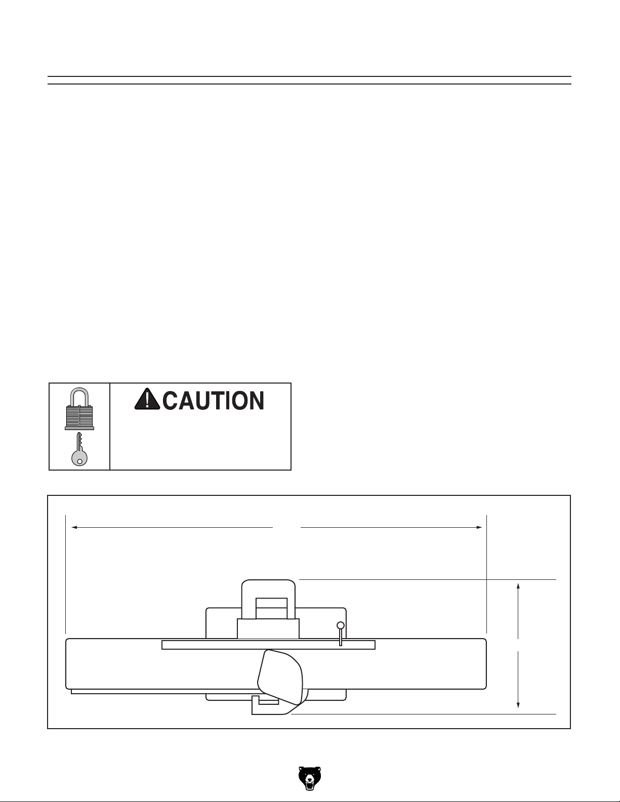
46"
27½"
Figure 9. Minimum working clearances.
Model G0452/P/Z (Mfg. Since 08/12)
-17-
Page 20

Locking Foot Pedal
3. Use a 13mm wrench to install the M8-1.25
x 50mm hex bolt and washer as shown in
Figure 11.
Components and Hardware Needed: Qty
Cabinet .............................................................. 1
Locking Foot Pedal Assembly ........................... 1
Hex Bolts M10-1.5 x 55 ..................................... 2
Flat Washers 10mm .......................................... 2
Hex Nuts M10-1.5 .............................................. 2
Hex Bolt M8-1.25 x 50 ....................................... 1
Flat Washer 8mm .............................................. 1
Tools Needed: Qty
Wrench 17mm .................................................. 1
Socket Wrench 17mm ....................................... 1
Wrench 13mm ................................................... 1
Level .................................................................. 1
To install the locking foot pedal:
1. Lay the cabinet on its side as shown in
Figure 10.
Note: The hex bolt installs from inside.
Figure 11. Installing locking foot pedal.
4. Install the M10-1.5 x 55 hex bolts, flat wash-
ers, and hex nuts through the front of the
locking foot pedal assembly as shown in
Figure 12.
Figure 10. Cabinet.
2. Place the locking foot pedal assembly onto
the cross brace.
Leveling
Feet
Figure 12. Installing locking foot pedal.
5. Raise the cabinet upright.
6. Lock the foot pedal down.
7. Level the cabinet front-to-back and side-
to -side by adjusting the leveling feet (see
Figure 12).
-18-
Model G0452/P/Z (Mfg. Since 08/12)
Page 21

Mounting Jointer
Components and Hardware Needed: Qty
Table Assembly ................................................. 1
Cabinet .............................................................. 1
Cap Screws M10-1.5 x 20 .................................. 3
Lock Washers 10mm ......................................... 3
Flat Washers 10mm .......................................... 3
Tools Needed: Qty
Hex Wrench 8mm ............................................. 1
Extra Person for Lifting Help ............................. 1
The jointer is heavy. Seek
assistance when lifting it
onto the jointer stand.
To mount the jointer to the stand:
4. Using the 8mm hex wrench, secure the jointer
to the cabinet with the M10-1.5 x 20 cap
screws, 10mm flat washers, and 10mm lock
washers.
Note: Reach through the dust vent for access
to the forward mounting hole as shown in
Figure 14.
1. Remove the access cover from the cabinet.
2. With the help of an assistant, lift the jointer
onto the cabinet.
3. Align the three bolt holes on the jointer with
the three holes on the cabinet (Figure 13).
Mounting Holes
Figure 14. Installing forward mounting bolt.
Figure 13. Mounting holes.
Model G0452/P/Z (Mfg. Since 08/12)
-19 -
Page 22
V-Belt
3. Carefully allow the motor to slide down, ten-
sioning the V-belts with the weight of the
motor.
Components and Hardware Needed: Qty
V-Belt ................................................................. 1
Tools Needed: Qty
Wrench or Socket 13mm .................................. 1
Hex Wrench 6mm .............................................. 1
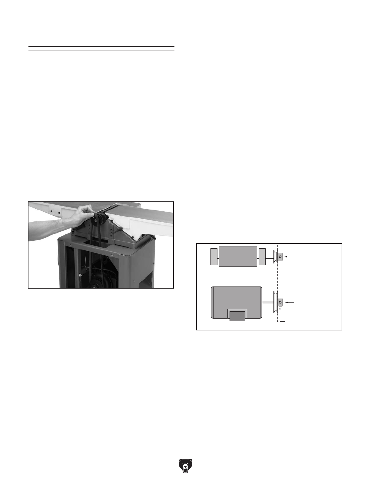
To install the V-belt:
1. Using a 13mm wrench, loosen, but DO NOT
remove the motor mount bolts.
2. Lift the motor up far enough to allow the
V-belts to be placed around the cutterhead
pulley and the motor pulley (see Figure 15).
4. Looking from the top, sight down the V-belt
and pulleys and check to see that the pulleys
are parallel and aligned with each other (see
Figure 16).
— If the pulleys are aligned, tighten the
motor mounts loosened in Step 1 and go
to Step 7.
— If the pulleys are NOT aligned, perform
Steps 5 & 6.
5. Remove the V-belt, loosen the set screws
on the end of the motor pulley, and align
the motor pulley with the cutterhead pulley.
If needed, the motor can be loosened and
moved in or out to bring the motor pulley into
alignment with the cutterhead pulley.
6. Tighten the set screws, replace the V-belts,
and repeat Step 4. Belts should be parallel
and aligned as shown in Figure 16.
Figure 15. Installing V-belt.
Cutterhead
Motor
Alignment
Cutterhead
Pulley
Motor Pulley
Setscrew
Figure 16. The pulleys should be parallel and
aligned.
7. Replace the access cover on the cabinet.
-20-
Model G0452/P/Z (Mfg. Since 08/12)
Page 23
Carriage Mounting
Bracket
Components and Hardware Needed: Qty
Carriage Mounting Bracket ................................ 1
Cap Screws M8-1.25 x 60 ................................. 4
Lock Washers 8mm ........................................... 4
Flat Washers 8mm ............................................ 4
Tools Needed: Qty
Hex Wrench 6mm ............................................. 1
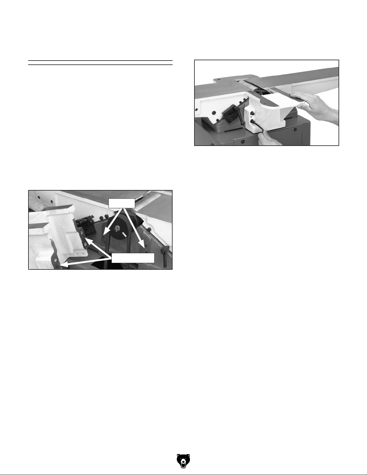
2. Tighten the carriage mounting bracket to the
jointer table with the cap screws, lock washers, and flat washers (see Figure 18).
To install the carriage mounting bracket:
1. Align the locating pins on the back of the car-
riage mounting bracket with the sockets on
the jointer table (see Figure 17).
Sockets
Locating Pins
Figure 17. Locating pins.
Figure 18. Assembled carriage mounting
bracket.
Model G0452/P/Z (Mfg. Since 08/12)
-21-
Page 24
Fence Carriage
Assembly
Components and Hardware Needed: Qty
Fence Carriage Assembly ................................. 1
Cap Screws M8-1.25 x 20 ................................. 2
Lock Washers 8mm ........................................... 2
Flat Washers 8mm ............................................ 2
Tools Needed: Qty
Hex Wrench 6mm ............................................. 1
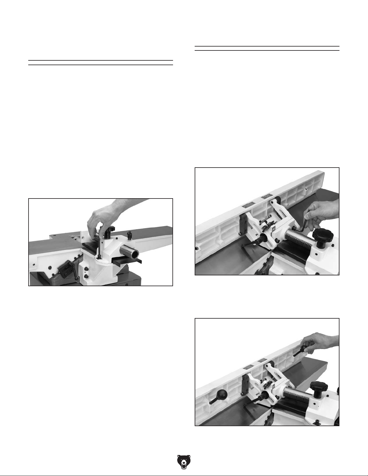
To install the fence carriage assembly:
1. Use the M8-1.25 x 20 cap screws, lock wash-
ers, and flat washers to secure the fence
carriage assembly to the carriage mounting
bracket (see Figure 19).
Fence Assembly
Components and Hardware Needed: Qty
Fence Assembly ................................................ 1
Cap Screws M8-1.25 x 25 ................................. 2
Lock Washers 8mm ........................................... 2
Flat Washers 8mm ............................................ 2
Fence Tilting Handles ........................................ 2
To install the fence carriage assembly:
1. Use the M8-1.25 x 25 cap screws, lock wash-
ers, and flat washers to secure the fence
assembly to the fence carriage assembly (see
Figure 20).
Figure 19. Fence carriage assembly.
Figure 20. Installing fence assembly.
2. Thread the fence tilting handles into the fence
(see Figure 21).
Figure 21. Installing fence tilting handles.
-22-
Model G0452/P/Z (Mfg. Since 08/12)
Page 25
Cutterhead Guard
The cutterhead guard is a critical safety
feature on this machine. A torsion spring is
mounted on the cutterhead guard shaft to
help it return to its proper position over the
cutterhead after a cutting operation. This
torsion spring must have spring pressure
during guard installation to work properly.
Torsion Spring
Knob
Components and Hardware Needed: Qty
Cutterhead Guard .............................................. 1
Tools Needed: Qty
Hex Wrench 2.5mm .......................................... 1
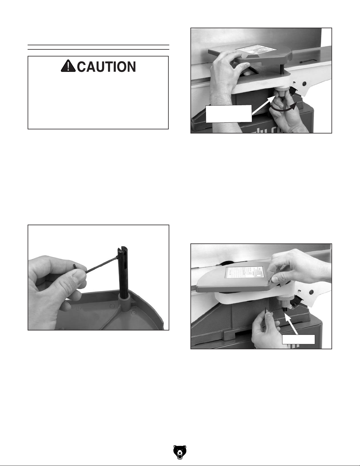
To install the cutterhead guard:
1. Remove the set screw in the cutterhead guard
shaft (see Figure 22).
Figure 23. Setting torsion spring knob.
3. Test the guard by pulling it back and letting
go.
—The guard should snap back over the
cutterhead. If it does, re-insert the set
screw (see Figure 24).
—If the guard is slow to return across the
table, remove the shaft, and add a half turn
to the spring knob and test again. Repeat
this step as necessary.
Figure 22. Set screw location.
2. Wind the torsion spring knob back counter-
clockwise a half turn, and slide the guard
shaft into the casting shown in Figure 23.
Make sure the slot on the cutterhead guard
shaft fits over the pin that sits inside the
spring knob barrel (hidden from view).
Model G0452/P/Z (Mfg. Since 08/12)
Set Screw
Figure 24. Re-installing set screw.
-23-
Page 26

Dust Port Dust Collection
Components and Hardware Needed: Qty
Dust Port ........................................................... 1
Phillips Head Screws M5-.8 x 15 ....................... 4
Flat Washers 5mm ............................................ 4
Tools Needed: Qty
Phillips Head Screwdriver .................................. 1
To install the dust port:
This machine creates a lot of wood chips/
dust during operation. Breathing airborne
dust on a regular basis can result in permanent respiratory illness. Reduce your risk
by wearing a respirator and capturing the
dust with a dust collection system.
Note: If you choose to not use a dust collection
system, don't install the dust port. Chips will build
up inside the cabinet and clog.
1. Place the dust port over the dust vent in the
side of the cabinet.
2. Use the M5-.8 x 15 Phillips head screws and
flat washers to secure the dust port to the
cabinet (see Figure 25).
Recommended CFM at Dust Port: 400 CFM
Do not confuse this CFM recommendation with
the rating of the dust collector. To determine the
CFM at the dust port, you must consider these
variables: (1) CFM rating of the dust collector,
(2) hose type and length between the dust collector and the machine, (3) number of branches
or wyes, and (4) amount of other open lines
throughout the system. Explaining how to calculate these variables is beyond the scope of
this manual. Consult an expert or purchase a
good dust collection "how-to" book.
To connect a dust collection hose:
1. Fit the 4" dust hose over the dust port, as
shown in Figure 25, and secure in place with
a hose clamp.
2. Tug the hose to make sure it does not come
off. Note: A tight fit is necessary for proper
performance.
Figure 25. Dust port installation.
3. Attach to dust collection system.
-24-
Model G0452/P/Z (Mfg. Since 08/12)
Page 27

Power Switch
Handwheels
Components and Hardware Needed: Qty
Power Switch & Support Arm ............................ 1
Cap Screws M8-1.25 x 25 ................................. 2
Flat Washers 8mm ............................................ 2
Tools Needed: Qty
Hex Wrench 6mm .............................................. 1
To install the power switch & support arm:
1. Install the support arm with the M8-1.25 x
25 cap screws and flat washers as shown in
Figure 26.
Components and Hardware Needed: Qty
Outfeed Table Handwheel ................................. 1
Phillips Head Screw M5-.8 x 15 ........................ 1
Flat Washer 5mm .............................................. 1
Tools Needed: Qty
Phillips Head Screwdriver .................................. 1
To install the handwheel:
1. Remove the screw and flat washer already
mounted to the handwheel shaft.
2. Secure the handwheel to the shaft with the
hardware removed in Step 1.
Figure 26. Installing support arm.
2. Plug the motor cord into the back of the
switch box, then secure the loose cords with
the hold downs shown in Figure 27.
Power Cord
Hold Downs
Figure 27. Cord locations.
Motor Cord
Figure 28. Securing the handwheel.
Model G0452/P/Z (Mfg. Since 08/12)
-25-
Page 28

Infeed Table Lever
Components and Hardware Needed: Qty
Infeed Table Lever ............................................. 1
Tools Needed: Qty
Wrench 19mm ................................................... 1
To set the outfeed table height for knives:
1. Place a straightedge on the outfeed table so it
extends over the cutterhead.
2. Rotate the cutterhead pulley until one of the
knives is at top-dead-center (TDC), as illustrated in Figure 30.
To install the infeed table lever:
1. Thread the infeed table lever into the hole
shown in Figure 29.
2. Tighten the locknut with a 19mm wrench.
Figure 29. Installing infeed table lever.
Setting Outfeed
Top Dead
Center
Figure 30. Cutterhead knife at top-dead-center.
3. Raise or lower the outfeed table until the knife
just touches the straightedge (Figure 31).
Straightedge
Outfeed Infeed
Table Height
For Models G0452/G0452P
The outfeed table must be level with the knives
when they are at top-dead-center. This adjustment has been made at the factory but should
be checked again before operating your jointer.
This adjustment will also have to be made any
time you perform maintenance on the cutterhead
or knives.
-26-
Figure 31. Using a straightedge to align outfeed
table height with knife at TDC.
4. Lock the outfeed table in Figure 32.
Figure 32. Outfeed table lock.
Model G0452/P/Z (Mfg. Since 08/12)
Page 29

For Model G0452Z
The outfeed table height MUST be level with the
carbide inserts when they are at top-dead-center.
If the outfeed table is set too low, the workpiece
will be tapered from front to back. If the outfeed
table is set too high, the workpiece will hit
the edge of the outfeed table during operation,
increasing the chance of kickback.
—If your outfeed table is correctly set, no
adjustments are necessary.
—If the insert lifts the straightedge off the
table or is below the straightedge, loosen
outfeed table lock and adjust table height
until straightedge just touches an insert at
its highest point of rotation.
To set the outfeed table height:
1. DISCONNECT JOINTER FROM POWER!
2. Move the cutterhead guard out of the way or
remove it, and open the rear access panel.
3. Place a straightedge on the outfeed table
so it extends over the cutterhead and rotate
the cutterhead pulley until one of the carbide
inserts is at top-dead-center (TDC), as shown
in Figure 33.
Top Dead
Center
Figure 33. Cutterhead insert at top-dead-center.
Tip: Some advanced woodworkers have found
that they can virtually eliminate snipe by setting
the outfeed table in the following manner: Repeat
Steps 1-4 using a freshly exposed insert. Place
5
two pencil marks on the straightedge
⁄32" apart,
and place the outward mark on the edge of the
outfeed table, as shown in Figure 35.
Lower the outfeed table slightly so the insert
lifts the straightedge off the table. Rotate the
cutterhead clockwise—the straightedge should
5
move
⁄32" toward the infeed table and the inward
mark should be directly over the edge of the
outfeed table, as shown in Figure 36. Continue
adjusting the outfeed table until the cutterhead
5
moves the straightedge
⁄32" toward the infeed
table.
Outward
Mark
Straightedge
4. When correctly set, the carbide insert will just
touch the straightedge when the insert is at
its highest point of rotation (see Figure 34).
Straightedge
Outfeed Infeed
Figure 34. Using a straightedge to align the
outfeed table height with insert at TDC.
Model G0452/P/Z (Mfg. Since 08/12)
Outfeed Infeed
Figure 35. Straightedge outward mark at edge of
outfeed table.
Inward
Mark
5
⁄32"
Outfeed Infeed
Figure 36. Straightedge inward mark at edge of
outfeed table.
5. Lock the outfeed table, re-install the
cutterhead guard, and close the rear access
panel.
-27-
Page 30

ON / START
Button
Pin
OFF / STOP
Paddle
Test Run
Once assembly is complete, test run the machine
to ensure it is properly connected to power and
safety components are functioning correctly.
If you find an unusual problem during the test run,
immediately stop the machine, disconnect it from
power, and fix the problem BEFORE operating the
machine again. The
table in the
SERVICE section of this manual can help.
DO NOT start machine until all preceding
setup instructions have been performed.
Operating an improperly set up machine
ed results that can lead to serious injury,
Serious injury or death can result from
Troubleshooting
using this machine BEFORE understanding
its controls and related safety information.
DO NOT operate, or allow others to operate,
machine until the information is understood.
5. Insert disabling pin through switch button
(see Figure 37).
Figure 37. Disabling pin through switch button.
6. Try to start machine by pressing switch but-
ton.
Machine should NOT start. If it does start,
the switch disabling feature is not functioning
properly and the switch must be replaced.
may result in malfunction or unexpect-
death, or machine/property damage.
To test run machine:
1. Clear all setup tools away from machine.
2. Make sure the cutterhead guard is installed
and correctly adjusted (Page 23).
3. Connect machine to power supply.
4. Turn machine ON. Verify motor operation,
and then turn machine OFF.
The motor should run smoothly and without
unusual problems or noises.
Recommended
Adjustments
For your convenience, the adjustments listed
below have been performed at the factory and no
further setup is required to operate your machine.
However, because of the many variables involved
with shipping, we recommend that you at least
verify the following adjustments to ensure the best
possible results from your new machine.
Step-by-step instructions for these adjustments
can be found in SECTION 7: SERVICE on Page
42.
Factory adjustments that should be verified:
1. Knife Settings (Page 44).
2. Insert Settings (Page 46).
-28-
3. Depth Scale Calibration (Page 47).
4. Fence Stop Accuracy (Page 48).
Model G0452/P/Z (Mfg. Since 08/12)
Page 31

SECTION 4: OPERATIONS
The purpose of this overview is to provide the novice machine operator with a basic understanding
of how the machine is used during operation, so
the
discussed later
in this manual
Due to the generic nature of this overview, it is
not intended to be an instructional guide. To learn
more about specific operations, read this entire
manual and
rienced
research outside of this manual by reading "howto" books, trade magazines, or websites.
To reduce your risk of
serious injury, read this
entire manual BEFORE
To reduce risk of eye injury from flying
Operation Overview
This overview gives you the basic process that
happens during an operation with this machine.
Familiarize yourself with this process to better
understand the remaining parts of the Operation
section.
machine controls/components
are easier to understand.
seek additional training from expe
machine operators, and do additional
using machine.
chips or lung damage from breathing dust,
always wear safety glasses and a respirator
when operating this machine.
To complete a typical operation, the operator
does the following:
1. Examines the workpiece to make sure it is
suitable for cutting.
2. Adjusts the fence for the width of the workpiece
and then locks it in place.
3. Adjusts the fence tilt, if necessary, to the cor-
rect angle.
4. Adjusts the infeed table height for the initial
cut.
5. Checks the outfeed side of the machine
for proper support and to make sure the
workpiece can safely pass all the way beyond
the cutterhead without interference from other
objects.
6. Wears safety glasses, respirator, and ear
protection, and locates the push blocks.
7. Starts the machine.
If you are not experienced with this type
of machine, WE STRONGLY RECOMMEND
that you seek additional training outside of
this manual. Read books/magazines or get
formal training before beginning any projects. Regardless of the content in this section, Grizzly Industrial will not be held liable
for accidents caused by lack of training.
Model G0452/P/Z (Mfg. Since 08/12)
8. Using the push blocks, holds the workpiece
firmly and flatly against both the infeed table
and fence, and then pushes the workpiece
past the cutterhead at a steady and controlled rate until the workpiece moves completely beyond the cutterhead.
9. Repeats Steps 5–8 until satisfied with the
results.
10. Stops the machine.
-29-
Page 32

Infeed Table
Adjustment
Proper infeed table adjustment must be made to
safely and efficiently use the jointer. DO NOT set
the infeed table depth greater than
first pass and never greater than
beting.
Serious personal injury could occur in the
event of a kickback. Kickback can occur
if excessive depth of cut is made. Limit a
single pass from
1
⁄16" to 1⁄8".
1
⁄16" on your
1
⁄8" when rab-
2. Use the infeed table lever to raise or lower
the infeed table (Figure 39).
Figure 39. Adjusting infeed table height.
To adjust the infeed table:
1. Loosen the infeed table lock in Figure 38.
Table Stop Lock Nuts
Infeed Table Lock
Figure 38. Infeed table lock.
3. Use the depth of cut scale to set the infeed
table to the desired depth and lock the table
in position.
Note: The infeed table stops can be adjusted
to return the table height to the same height
every time by loosening the lock nuts and
adjusting the set screws.
-30-
Model G0452/P/Z (Mfg. Since 08/12)
Page 33

Stock Inspection and
Requirements
• Remove foreign objects from the stock.
Make sure that any stock you process with
the jointer is clean and free of any dirt,
nails, staples, tiny rocks or any other foreign
objects that may damage the jointer blades.
Here are some rules to follow when choosing and jointing stock:
• DO NOT joint or surface plane stock that
contains knots. Injury to the operator or
damage to the workpiece can occur if the
knots become dislodged during the cutting
operation.
• DO NOT joint or surface plane against the
grain direction. Cutting against the grain
increases the likelihood of stock kickback, as
well as tear-out on the workpiece.
• Jointing and surface planing with the
grain produces a better finish and is safer
for the operator. Cutting with the grain is
described as feeding the stock on the jointer
so the grain points down and toward you as
viewed on the edge of the stock (Figure 40).
Note: If the grain changes direction along the
edge of the board, decrease the cutting depth
and make additional passes.
• Only process natural wood fiber through
your jointer. Never joint MDF, particle board,
plywood, laminates or other synthetically
made materials.
• Make sure all stock is sufficiently dried
before jointing. Wood with a moisture content over 20% will cause unnecessary wear
on the knives and poor cutting results.
• Make sure your workpiece exceeds
the minimum dimension requirements
(Figures 41 & 42 ) before edge jointing or
surface planing, or it may break or kick
back during the operation!
10" Min.
1" Min.
Figure 40. Correct and incorrect grain alignment
to cutterhead.
1
⁄2" Min.
Figure 41. Minimum dimensions for edge
jointing.
10" Min.
1
⁄2" Min.
1" Min.
Figure 42. Minimum dimensions for surface
planing.
Model G0452/P/Z (Mfg. Since 08/12)
-31-
Page 34

Squaring Stock
Squaring stock involves four steps performed
Previously Surface
Planed Face
in the order below:
1. Surface Plane on the Jointer—The concave
face of the workpiece is surface planed flat with
the jointer.
2. Surface Plane on a Thickness Planer—The
opposite face of the workpiece is surface planed
flat with a thickness planer.
Surface Planing
If you are not experienced with a jointer,
set the depth of cut to 0", and practice
feeding the workpiece across the tables as
described. This procedure will better prepare you for the actual operation.
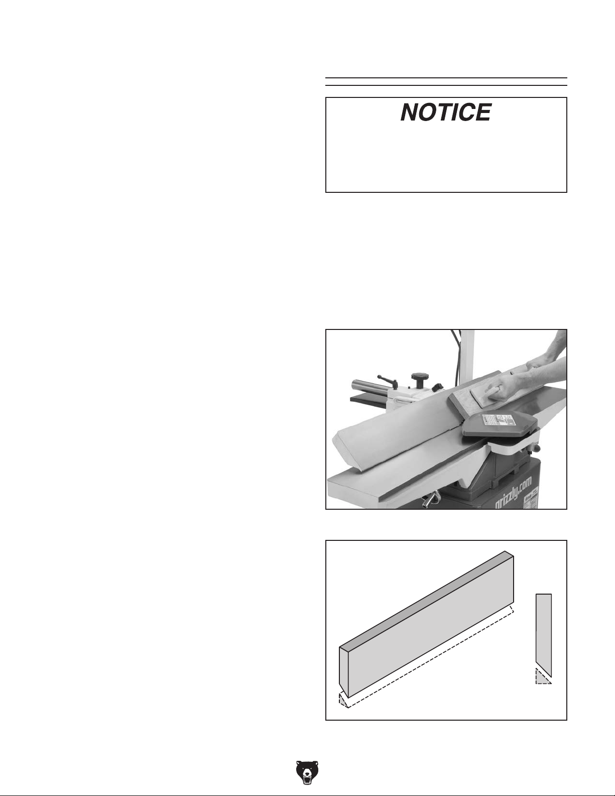
The purpose of surface planing on the jointer is
to make one flat face on a piece of stock (see
Figures 43 & 44) to prepare it for thickness planing on a planer.
3. Edge Joint on the Jointer—The concave
edge of the workpiece is jointed flat with the
jointer.
4. Rip Cut on a Table Saw—The jointed edge
of the workpiece is placed against a table saw
fence and the opposite edge cut off.
Previously
Jointed
45
30
15
Edge
Figure 43. Typical surface planing operation.
Figure 44. Illustration of surface planing results.
-32-
Model G0452/P/Z (Mfg. Since 08/12)
Page 35

To surface plane on the jointer:
1. Read and understand SECTION 1: SAFETY,
beginning on Page 7.
2. Make sure your stock has been inspected
for dangerous conditions as described in the
Stock Inspection & Requirements instructions, beginning on Page 31.
3. Set the cutting depth for your operation. (We
suggest
shallow depth for hard wood species or for
wide stock.)
4. Make sure your fence is set to 90˚.
5. If your workpiece is cupped (warped), place it
so the concave side is face down (Figure 44)
on the surface of the infeed table.
6. Start the jointer.
1
⁄32" for surface planing, using a more
Edge Jointing
If you are not experienced with a jointer,
set the depth of cut to 0", and practice
feeding the workpiece across the tables as
described below. This procedure will better
prepare you for the actual operation.
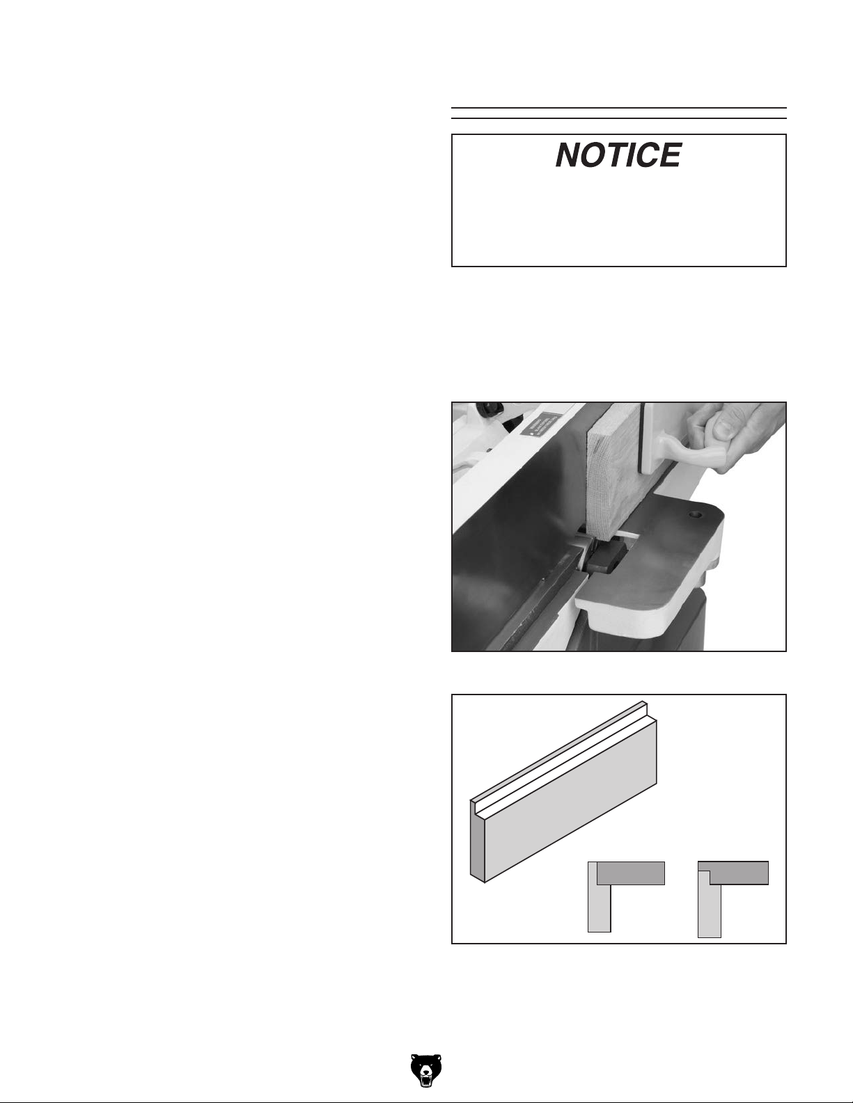
The purpose of edge jointing is to produce a finished, flat-edged surface (see Figures 45 & 46)
that is suitable for joinery or finishing. It is also a
necessary step when squaring rough or warped
stock.
Failure to use push blocks when surface
planing may result in cutterhead contact,
which will cause serious personal injury.
Always use push blocks to protect your
hands when surface planing on the jointer.
7. With a push block in each hand, press the
workpiece against the table and fence with
firm pressure, and feed the workpiece over
the cutterhead (see Figure 43).
Note: When your leading hand (with push
block) gets within 4" of the cutterhead, lift it
up and over the cutterhead, and place the
push block on the portion of the workpiece
that is on the outfeed table. Now, focus your
pressure on the outfeed end of the workpiece
while feeding, and repeat the same action
with your trailing hand when it gets within 4"
of the cutterhead. To keep your hands safe,
DO NOT let them get closer than 4" from the
cutterhead when it is moving!
Figure 45. Typical edge jointing operation.
8. Repeat Step 7 until the entire surface is flat.
Note: If 2nd surface is jointed it will not likely
be parallel with the 1st, so the best approach
is to joint one surface, then plane the other
with a thickness planer.
Model G0452/P/Z (Mfg. Since 08/12)
Figure 46. Illustration of edge jointing results.
-33-
Page 36
To edge joint on the jointer:
1. Read and understand SECTION 1: SAFETY,
beginning on Page 7.
2. Make sure your stock has been inspected
for dangerous conditions as described in the
Stock Inspection instructions, beginning on
Page 31.
3. Set the cutting depth for your operation. (We
suggest between
ing, using a more shallow depth for hard
wood species or for wide stock.)
4. Make sure the fence is set to 90˚.
1
⁄16" and 1⁄8" for edge joint-
Bevel Cutting
If you are not experienced with a jointer,
set the depth of cut to 0", and practice
feeding the workpiece across the tables as
described below. This procedure will better
prepare you for the actual operation.
The purpose of bevel cutting is to cut a specific
angle into the edge of a workpiece (see Figures
47 & 48).
5. If your workpiece is cupped (warped), place it
so the concave side is face down (Figure 46)
on the surface of the infeed table.
6. Start the jointer.
7. Press the workpiece against the table and
fence (Figure 45) with firm pressure. Use
your trailing hand to guide the workpiece
through the cut, and feed the workpiece over
the cutterhead.
Note: When your leading hand gets within
4" of the cutterhead, lift it up and over the
cutterhead, and place it on the portion of
the workpiece that is over the outfeed table.
Now, focus your pressure on the outfeed end
of the workpiece while feeding, and repeat
the same action with your trailing hand when
it gets within 4" of the cutterhead. To keep
your hands safe, DO NOT let them get closer
than 4" from the cutterhead when it is moving!
The Model G0452 has preset fence stops at 45˚
inward, 90˚, and 45˚ outward (135˚). If your situation requires a different angle, the preset fence
stops can be easily adjusted for your needs.
Figure 47. Typical bevel cutting operation.
8. Repeat Step 7 until the entire edge is flat.
Note: If 2nd edge is jointed it will not likely be
parallel with the 1st, so instead of jointing the
second edge, trim it with a table saw. This
will ensure both edges are parallel with each
other.
-34-
Figure 48. Illustration of bevel cutting results.
Model G0452/P/Z (Mfg. Since 08/12)
Page 37
To bevel cut on the jointer:
1. Read and understand SECTION 1: SAFETY,
beginning on Page 7.
2. Make sure your stock has been inspected
for dangerous conditions as described in the
Stock Inspection instructions, beginning on
Page 31.
3. Set the cutting depth for your operation. (We
suggest between
ting, using a more shallow depth for hard
wood species or for wide stock.)
4. Make sure your fence is set to the angle of
your desired cut.
5. If your workpiece is cupped (warped), place
it so the concave side is face down on the
surface of the infeed table.
6. Start the jointer.
1
⁄16" and 1⁄8" for bevel cut-
Rabbet Cutting
If you are not experienced with a jointer,
set the depth of cut to 0", and practice
feeding the workpiece across the tables as
described below. This procedure will better
prepare you for the actual operation.
The purpose of rabbet cutting is to remove a section of the workpiece edge (see Figures 49 & 50).
When combined with another rabbet cut edge, the
rabbet joints create a simple, yet strong method of
joining stock.
7. With a push block in your leading hand, press
the workpiece against the table and fence
with firm pressure, and feed the workpiece
over the cutterhead.
Note: When your leading hand gets within
4" of the cutterhead, lift it up and over the
cutterhead, and place the push block on the
portion of the workpiece that is on the outfeed
table. Now, focus your pressure on the
outfeed end of the workpiece while feeding,
and repeat the same action with your trailing
hand when it gets within 4" of the cutterhead.
To keep your hands safe, DO NOT let them
get closer than 4" from the cutterhead when
it is moving!
8. Repeat Step 7 until the angled cut is satisfactory to your needs.
Figure 49. Typical rabbet cutting operation.
Model G0452/P/Z (Mfg. Since 08/12)
Figure 50. Illustration of rabbet cutting effects
and a few sample joints.
-35-
Page 38

6. Start the jointer.
When the cutterhead guard is removed,
attempting any other cut besides a rabbet
directly exposes the operator to the moving
cutterhead. Always replace the cutterhead
guard after rabbet cutting!
To rabbet cut on the jointer:
1. Read and understand SECTION 1: SAFETY,
beginning on Page 7.
2. Make sure your stock has been inspected
for dangerous conditions as described in the
Stock Inspection instructions, beginning on
Page 31.
3. Set the cutting depth for your operation. (We
1
suggest between
⁄16" and 1⁄8" for rabbet cutting, using a more shallow depth for hard
wood species or for wide stock.)
4. Remove the cutterhead guard.
7. With a push block in each hand, press the
workpiece against the table and fence with
firm pressure, and feed the workpiece over
the cutterhead.
Note: When your leading hand gets within
4" of the cutterhead, lift it up and over the
cutterhead, and place the push block on
the portion of the workpiece that is on the
outfeed table. Now, focus your pressure on
the outfeed end of the workpiece while feeding, and repeat the same action with your
trailing hand when it gets within 4" of the
cutterhead. To keep your hands safe, DO
NOT let them get closer than 4" from the
cutterhead when it is moving!
8. Repeat Step 7 until the your rabbet is cut to
depth.
5. Make sure your fence is moved forward, so
the amount of infeed/outfeed table exposed
is the same as the size of your rabbet. Also,
make sure your fence is set to 90˚.
-36-
Model G0452/P/Z (Mfg. Since 08/12)
Page 39

SECTION 5: ACCESSORIES
Installing unapproved accessories may
order online at www.grizzly.com or call 1-800-523-4777
cause machine to malfunction, resulting in
serious personal injury or machine damage.
To reduce this risk, only install accessories
recommended for this machine by Grizzly.
NOTICE
Refer to our website or latest catalog for
additional recommended accessories.
W1212—Woodstock Jointer Pal
This knife-setting system lets you set jointer
knives in perfect alignment every time! It also
allows you to shift nicked knives to get a perfect
cut to an accuracy of + or - .001".
G3631—Jointer/Planer Knife Hone
Add a razor hone to your planer and jointer knives
with this hand-held sharpening device. This handy
tool sharpens flat and beveled surfaces quickly
and easily. Great for touch-ups.
Figure 51. Jointer knife jig.
Figure 52. Jointer knife hone.
T23246—The Missing Shop Manual: Jointer
Dedicated to providing integral information about
woodworking tools and techniques that other
manuals overlook, the books in this series contain safety facts, explanations about basic project
set-up, and tips for maximizing tool performance.
Figure 57. Instructional reference book.
Model G0452/P/Z (Mfg. Since 08/12)
-37-
Page 40

T21992—1⁄2" x 4' Power Twist V-Belt
Perfect for lathes, table saws, bandsaws and
other powered tools. Smooth running with less
®
vibration than solid belts. Power Twist
V-Belts
can be customized in minutes to any size—just
add or remove sections to fit your needs. Carry a
®
Power Twist
V-Belt in your vehicle for a fix any-
where solution to broken fan belts.
Figure 54. Power Twist V-Belt.
G5562—SLIPIT 1 Qt. Gel
G5563—SLIPIT 12 oz Spray
Use on cast iron table surfaces and other unpainted metal surfaces to reduce sliding friction and
hangups. This product also reduces rust and prevents resin build-up.
H9876—6" x
These 6" x
5
⁄8" x 1⁄8" HSS Jointer Knives
5
⁄8" x 1⁄8" Jointer Knives are made
from HSS steel and are for our G0452 6" Jointer.
Figure 56. Jointer Knives.
T21146—Self-Set System
(Includes 3 Holders & Knife Inserts)
G6665—Dispoz-A-Blade
Knife Inserts
(Set of 3)
®
Install a Dispoz-A-Blade
Knife system in your
new jointer and save up to 70% on knife replacements for the life of your jointer. Each knife insert
is double-edged, so you get two knives in one,
and is indexed so that all knife inserts can be
installed at the same height in just minutes. Yes,
that means you can throw away the knife jig!
-38-
Figure 53. Blade holder and knife.
Figure 55. Table gel and spray.
Model G0452/P/Z (Mfg. Since 08/12)
Page 41

T10125—6" Spiral Cutterhead
We’ve found yet another source for high quality
Spiral Cutterheads. These Cutterheads feature 4
spirals and German-made carbide inserts for an
incredible finish.
Figure 58. Spiral Cutterhead.
H7653—6" Spiral Cutterhead
This cutterhead replaces the standard straight
knife cutterheads on our Grizzly jointers. It has
four spirals with indexable, four-sided carbide
inserts, so each insert can be rotated for a new
factory sharp edge. Cutterhead includes cast iron
pulleys, bearing blocks, mounting studs, 5 extra
inserts, T-handle wrench, Torx bits and spare
insert screws. Has an incredible finish, and is
comparable to Byrd cutterheads in quality of cut
as well as the quality of the cutterhead itself.
H7764—Byrd Tool 6" Shelix Cutterhead
Made in the USA by Byrd, these indexable carbide insert cutterheads are very well made and
leave a great finish. The inserts are positioned
along a spiral pattern, and rotate at a slight angle
for a shearing action that leaves a glassy smooth
cut on the toughest of woods. Comes with all 30
inserts on the cutterhead, plus 5 extras.
Figure 60. Shelix Cutterhead.
T21348—Carbide Replacement Inserts
Solid Carbide Indexable Inserts for Cutterheads.
Size: 14 x 14 x 2mm (10 pack).
Figure 59. Spiral Cutterhead.
Model G0452/P/Z (Mfg. Since 08/12)
Figure 61. Replacement inserts.
-39-
Page 42

order online at www.grizzly.com or call 1-800-523-4777
G9643—8" Precision Straightedge
G9644—12" Precision Straightedge
H2675—16" Precision Straightedge
Is your straightedge really straight? These grade
00 heavy-duty stainless steel straightedges are
manufactured to DIN874 standards for professional results in set-up and inspection work.
Figure 62. Straightedges.
G9256—6" Dial Caliper
G9257—8" Dial Caliper
G9258—12" Dial Caliper
Required for jointing, planing, or sanding to critical tolerances. These traditional dial calipers are
accurate to 0.001" and can measure outside
surfaces, inside surfaces, and heights/depths.
Features stainless steel, shock resistant construction and a dust proof display. An absolute treat for
the perfectionist!
H8029—5 Piece Safety Kit
This kit has four essential jigs. Includes two
push blocks, push stick, featherboard and combination saw and router gauge. Featherboard
3
⁄8" x 3⁄4" miter slots. Made of high visibility
fits
yellow plastic.
Figure 63. 5-Piece Safety Kit.
®
Figure 64. Grizzly
Dial Calipers.
T20501—Face Shield Crown Protector 4"
T20502—Face Shield Crown Protector 7"
T20503—Face Shield Window
T20452—"Kirova" Anti-Reflective S. Glasses
T20451—"Kirova" Clear Safety Glasses
H7194—Bifocal Safety Glasses 1.5
H7195—Bifocal Safety Glasses 2.0
H7196—Bifocal Safety Glasses 2.5
T20502
T20452
T20503
T20451
H7194
Figure 65. Eye protection assortment.
-40-
Model G0452/P/Z (Mfg. Since 08/12)
Page 43

SECTION 6: MAINTENANCE
To reduce risk of shock or
accidental startup, always
disconnect machine from
power before adjustments,
maintenance, or service.
Schedule
For optimum performance from your machine,
follow this maintenance schedule and refer to any
specific instructions given in this section.
Daily:
• Vacuum all dust on and around the
machine.
• Wipe down tables and all other unpainted
cast iron with a metal protectant.
Monthly Check:
• V-belt tension, damage, or wear.
• Clean/vacuum dust buildup from inside cabinet and off of motor.
Cleaning
Cleaning the Model G0452/P/Z is relatively easy.
Vacuum excess wood chips and sawdust, and
wipe off the remaining dust with a dry cloth. If any
resin has built up, use a resin dissolving cleaner
to remove it. Treat all unpainted cast iron and
steel with a non-staining lubricant after cleaning.
Unpainted Cast Iron
Protect the unpainted cast iron surfaces on the
table by wiping the table clean after every use—
this ensures moisture from wood dust does not
remain on bare metal surfaces.
Keep tables rust-free with regular applications of
products like G96
Boeshield
Page 37 for more details).
®
T-9 (see Section 5: Accessories on
®
Gun Treatment, SLIPIT®, or
Lubrication
V-Belt
To ensure optimum power transmission from the
motor to the blade, the V-belt must be in good
condition (free from cracks, fraying and wear)
and properly aligned and tensioned (refer to the
instructions on Page 20).
Model G0452/P/Z (Mfg. Since 08/12)
Since all bearings are sealed and permanently
lubricated, simply leave them alone until they
need to be replaced. DO NOT lubricate them.
Table ways and the fence assembly should not
be lubricated. If the tables appear to be stuck,
disassemble and clean any foreign materials
from the ways. Re-assemble and reset the gibs.
-41-
Page 44

Review the troubleshooting and procedures in this section if a problem develops with your machine. If you
need replacement parts or additional help with a procedure, call our Technical Support at (570) 546-9663.
Note: Please gather the serial number and manufacture date of your machine before calling.
SECTION 7: SERVICE
Troubleshooting
Motor & Machine Operation
Symptom Possible Cause Possible Solution
Motor will not start.
Fuses or circuit breakers blow. 1. Short circuit in line cord or plug.
Motor fails to develop full power (output
of motor decreases rapidly with decrease
in voltage at motor terminals).
Motor overheats. 1. Motor overloaded during operation.
Motor stalls or shuts off during a cut. 1. Motor overloaded during operation.
Blade slows when cutting or makes a
squealing noise, especially on start-up.
Loud repetitious noise coming from
machine.
1. Emergency stop button depressed.
2. Low voltage.
3. Open circuit in motor or loose
connections.
1. Power supply circuit overloaded with
lights, appliances, and other motors.
2. Undersized wires or circuits too long.
2. Air circulation through the motor
restricted.
2. Short circuit in motor or loose
connections.
3. Circuit breaker tripped.
1. V-belt loose.
2. V-belt worn out.
1. Pulley setscrews or keys are missing
or loose.
2. Motor fan is hitting the cover.
3. V-belts are damaged.
1. Lift the cover on the emergency stop
button to allow it to pop out.
2. Check power line for proper voltage.
3. Inspect all lead connections on motor
for loose or open connections.
1. Repair or replace cord or plug for
damaged insulation and shorted
wires.
1. Reduce load on circuit.
2. Increase wire sizes or reduce length
of the circuit.
1. Reduce load on motor; take lighter
cuts.
2. Clean out motor to provide normal air
circulation.
1. Reduce load on motor; take lighter
cuts.
2. Repair or replace connections on
motor for loose or shorted terminals
or worn insulation.
3. Install correct circuit breaker; reduce
# of machines running on that circuit.
1. Tighten V-belt (Page 20).
2. Replace V-belt (Page 20).
1. Inspect keys and setscrews. Replace
or tighten if necessary.
2. Adjust fan cover mounting position,
tighten fan, or shim fan cover.
3. Replace V-belts (Page 20).
Vibration when running or cutting. 1. Loose or damaged blade.
2. Damaged V-belt.
3. Worn cutterhead bearings.
-42-
1. Tighten or replace blade.
2. Replace.
3. Check/replace cutterhead bearings.
Model G0452/P/Z (Mfg. Since 08/12)
Page 45

Table
Symptom Possible Cause Possible Solution
Tables are hard to adjust.
Excessive play in table
movement.
1. Table lock is engaged or partially engaged.
2. Table gibs are too tight.
1. Table gibs are too loose. 1. Re-adjust the table gibs (Page 49).
1. Completely loosen the table lock.
2. Re-adjust the table gibs (Page 49).
Cutting
Symptom Possible Cause Possible Solution
Excessive snipe (gouge in the
end of the board that is uneven
with the rest of the cut).
Workpiece stops in the middle
of the cut.
Chipping. 1. Knots or conflicting grain direction in
Long lines or ridges that run
along the length of the board.
Uneven cutter marks, wavy
surface, or chatter marks across
the face of the board.
Board edge is concave or
convex after jointing.
Uneven cut or breakout when
rabbeting.
1. Outfeed table is set too low.
2. Operator pushing down on end of
workpiece.
1. Outfeed table is set too high. 1. Align outfeed table with cutterhead knife at top
wood.
2. Nicked or chipped blades.
3. Feeding workpiece too fast.
4. Taking too deep of a cut.
1. Nicked or chipped knives. 1. Adjust one of the nicked knives sideways; or
1. Feeding workpiece too fast.
2. Knives not adjusted at even heights
in the cutterhead.
1. Board not held with even pressure on
infeed and outfeed table during cut.
2. Board started too uneven.
3. Board has excessive bow or twist
along its length.
4. Insufficient number of passes.
1. Uneven feed rate.
2. Depth of cut too deep.
3. Knives not adjusted evenly with each
other in the cutterhead.
4. Nicked or chipped knives.
1. Align outfeed table with cutterhead knife at top
dead center (Page 26).
2. Reduce/eliminate downward pressure on that
end of workpiece.
dead center (Page 26).
1. Inspect workpiece for knots and grain (Page
31); only use clean stock.
2. Adjust one of the nicked knives sideways; or
replace knives (Page 44).
3. Slow down the feed rate.
4. Take a smaller depth of cut. (Always reduce
cutting depth when surface planing or working
with hard woods.)
replace knives (Page 44).
1. Slow down the feed rate.
2. Adjust the knives so they are set up evenly in
the cutterhead (Page 44).
1. Hold board with even pressure as it moves
over the cutterhead.
2. Take partial cuts to remove the extreme high
spots before doing a full pass.
3. Surface plane one face so there is a good
surface to position against the fence.
4. It may take 3 to 5 passes to achieve a perfect
edge, depending on the starting condition of
the board and the depth of cut.
1. Feed the board evenly and smoothly during
the cut.
2. Raise the infeed table to take a smaller depth
of cut. Never exceed
rabbeting.
3. Adjust the knives so they are set up evenly in
the cutterhead (Page 44).
4. Adjust one of the nicked knives sideways;
replace knives (Page 44).
1
⁄16" per pass when
Model G0452/P/Z (Mfg. Since 08/12)
-43-
Page 46

3. Lower the infeed table to the
accidental startup, always
disconnect machine from
1
⁄2" scale mark.
To reduce risk of shock or
power before adjustments,
maintenance, or service.
About Service
This section is designed to help the operator with
adjustments that were made at the factory and
that might also need to be made during the life of
the machine.
This section is provided for your convenience—
it is not a substitute for the Grizzly Service
Department.
If any adjustments arise that are not described in
this manual or you are unsure of how to perform
the procedures in this section, then feel free to call
Technical Support at (570) 546-9663.
G0452/G0452P
Inspecting Knives
The height of the knives can be easily and
quickly inspected with the knife setting jig. This
inspection will ensure that the knives are set in
the cutterhead as they should be. Usually this is
done before calibrating the outside table or when
troubleshooting.
4. Place the knife jig on the cutterhead, directly
over a knife, as shown in Figure 66.
Middle
Pad
Figure 66. Jig positioned over cutterhead knife.
5. Carefully inspect how the jig touches the
cutterhead and the knife.
— If both outside legs of the jig sit firmly on
the cutterhead and the middle pad just
touches the knife, then that knife is set
correctly. (Repeat this inspection with the
other knives.)
— If the jig does not sit firmly on the cutterhead
and touch the knife edge as described, then
reset that knife. (Repeat this inspection
with the other knives before resetting.)
G0452/G0452P
Setting Knives
To inspect the knives:
1. DISCONNECT JOINTER FROM POWER!
2. Remove the cutterhead guard or block it out
of the way.
-44-
Setting the knives correctly is crucial to the proper
operation of the jointer and is very important in
keeping the knives sharp. If one knife is higher
than the others, it will do the majority of the work,
and thus, dull much faster than the others.
The knife jig included with the jointer is designed
to set the knives at the correct height.
Model G0452/P/Z (Mfg. Since 08/12)
Page 47

The G0452/P Jointer uses jack screws for
cutterhead knife height adjustments (see Figure
67).
Figure 67. Cutterhead profile diagram.
To set the knives:
1. DISCONNECT JOINTER FROM POWER!
2. Remove the cutterhead guard from the table
and lower the infeed and outfeed tables as
far as they go. This will give you unrestricted
access to the cutterhead.
3. Remove the cabinet cover to expose the V-
belt.
4. Use the V-belt to rotate the cutterhead to
access the cutterhead knives.
5. Loosen the cutterhead gib bolts, starting in
the middle, and alternating back and forth
until all of the gib bolts are loose, but not falling out.
7. Using a 3mm hex wrench, access the jack
screws through the holes in the cutterhead
(Figure 68) and rotate the jack screws to
raise or lower the knife. When the knife is set
correctly, it will barely touch the middle pad of
the knife setting jig. Snug the gib bolts tight
enough to just hold the knife in place. Repeat
Steps 5-7 with the rest of the knives.
Figure 68. Jack screw access hole.
8. Rotate the cutterhead to the first knife you
started with. Slightly tighten all the gib bolts,
starting at the ends and working your way
to the middle by alternating left and right.
Repeat this step on the rest of the knives.
9. Final tighten each gib bolt.
10. Adjust the outfeed table to match the new
knife heights.
6. Position the knife gauge over the knife as
shown in Figure 66 and loosen the gib bolts
until the knife is completely loose.
Model G0452/P/Z (Mfg. Since 08/12)
-45-
Page 48

G0452Z Replacing
Carbide Inserts
Tools Needed: Qty
L-Wrench Torx with T20 Torx Driver .................. 1
The Model G0452Z cutterhead is equipped with
32 indexable carbide inserts. Each insert can be
rotated to reveal any one of its four cutting edges.
Therefore, if one cutting edge becomes dull or
damaged, simply rotate it 90˚ to reveal a fresh
cutting edge (Figure 69).
Reference Dot
To rotate or change a carbide insert:
1. DISCONNECT JOINTER FROM POWER!
2. Move the cutterhead guard out of the way, or
remove it.
3. Remove any sawdust from the head of the
carbide insert Torx screw.
4. Remove the Torx screw and carbide insert.
5. Clean all dust and dirt off of the insert and
the cutterhead pocket from which the insert
was removed, and replace the insert so a
fresh, sharp edge is facing outward. Make
sure the insert is seated in the pocket on the
cutterhead.
Note: Proper cleaning is critical to achieving
a smooth finish. Dirt or dust trapped between
the insert and cutterhead will slightly raise the
insert, and make noticeable marks on your
workpieces the next time you cut.
Figure 69. Insert rotating sequence.
In addition, each insert has a reference dot on
one corner. As the insert is rotated, the reference
dot location can be used as an indicator of which
edges are used and which are new. When the
reference dot revolves back around to its starting
position, the insert should be replaced.
Replacement carbide inserts should be included
with the cutterhead. If you need additional inserts,
call Grizzly Customer Service at (800) 523-4777
and order Model T21348, Replacement Indexable
Carbide Inserts for G0452Z, 10 pack.
6. Lubricate the Torx screw threads with a
light machine oil, wipe the excess oil off the
threads, and torque the Torx screw to 48-50
inch/pounds.
Note: Excess oil may squeeze between the
insert and cutterhead or at the bottom of
the screw hole, causing hydrostatic lock and
preventing the screw from fully tightening,
thereby lifting the insert or screw slightly and
affecting workpiece finishes. Make sure to
carefully clean off any excess oil to prevent
this from happening.
-46-
Model G0452/P/Z (Mfg. Since 08/12)
Page 49
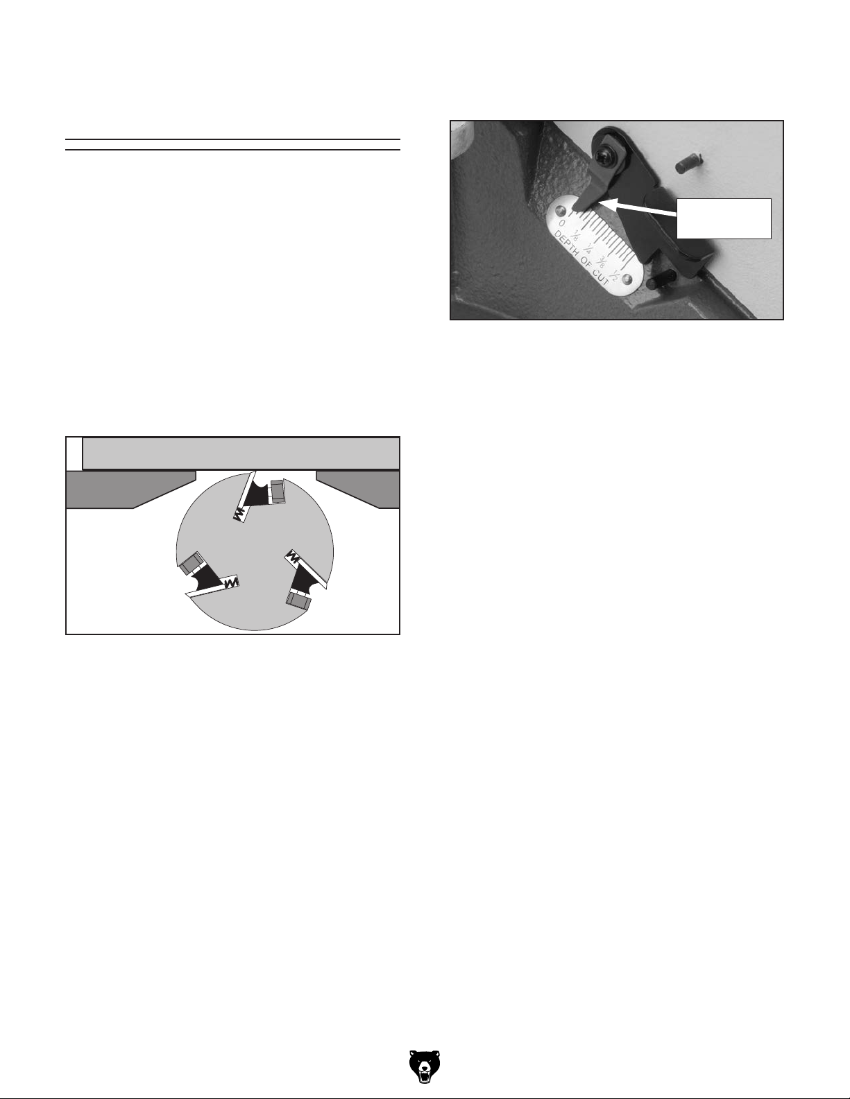
Infeed
Calibrating Depth
Scale
The depth scale on the infeed table can be calibrated or "zeroed" if it is not correct.
To calibrate the depth scale:
1. Set the outfeed table height as described
in the Setting Outfeed Table Height subsection.
4. Using a screwdriver, adjust the scale pointer
exactly to “0” (Figure 71).
Depth-of-cut
pointer
2. Place a straightedge across the infeed and
outfeed tables.
3. Adjust the infeed table until it is level with the
outfeed table, as illustrated in Figure 70.
Straightedge
Outfeed
Figure 70. Infeed table adjusted even with
outfeed table and knife at TDC.
Figure 71. Depth-of-cut pointer adjusted to “0”
position.
Model G0452/P/Z (Mfg. Since 08/12)
-47-
Page 50

Setting Fence Stops
The fence stops are adjustable nuts and bolts
that simplify the task of adjusting the fence to 45˚
inward, 90˚, and 45˚ outward (135˚).
To set the 45˚ inward fence stop:
To set the 90˚ fence stop:
1. Flip the 90˚ swing stop into the position
shown in Figure 74.
1. Using a 45˚ square, adjust the fence to the
45˚ inward position, as shown in Figure 72.
Figure 72. Adjusting fence 45˚ inward.
2. Loosen the jam nut shown in Figure 73.
Swing Stop
Jam Nut
Fence Stop Bolt
Figure 74. 90˚ swing stop engaged.
2. Using a 90˚ square, adjust the fence to the
90˚ position in Figure 75 using the fence stop
bolt and jam nut.
Fence Stop Nut
Jam Nut
Figure 73. 45˚ inward fence stop jam nut.
3. Adjust the 45˚ inward fence stop nut until it
makes contact with the back of the fence
bracket.
4. Retighten the jam nut loosened in Step 2 and
recheck.
-48-
Figure 75. Adjusting fence to 90˚.
3. Loosen the jam nut on the 90˚ fence stop bolt
(Figure 74).
4. Adjust the 90˚ fence stop bolt until it makes
contact with the 90˚ swing stop.
5. Retighten the jam nut loosened in Step 3 and
recheck.
Model G0452/P/Z (Mfg. Since 08/12)
Page 51
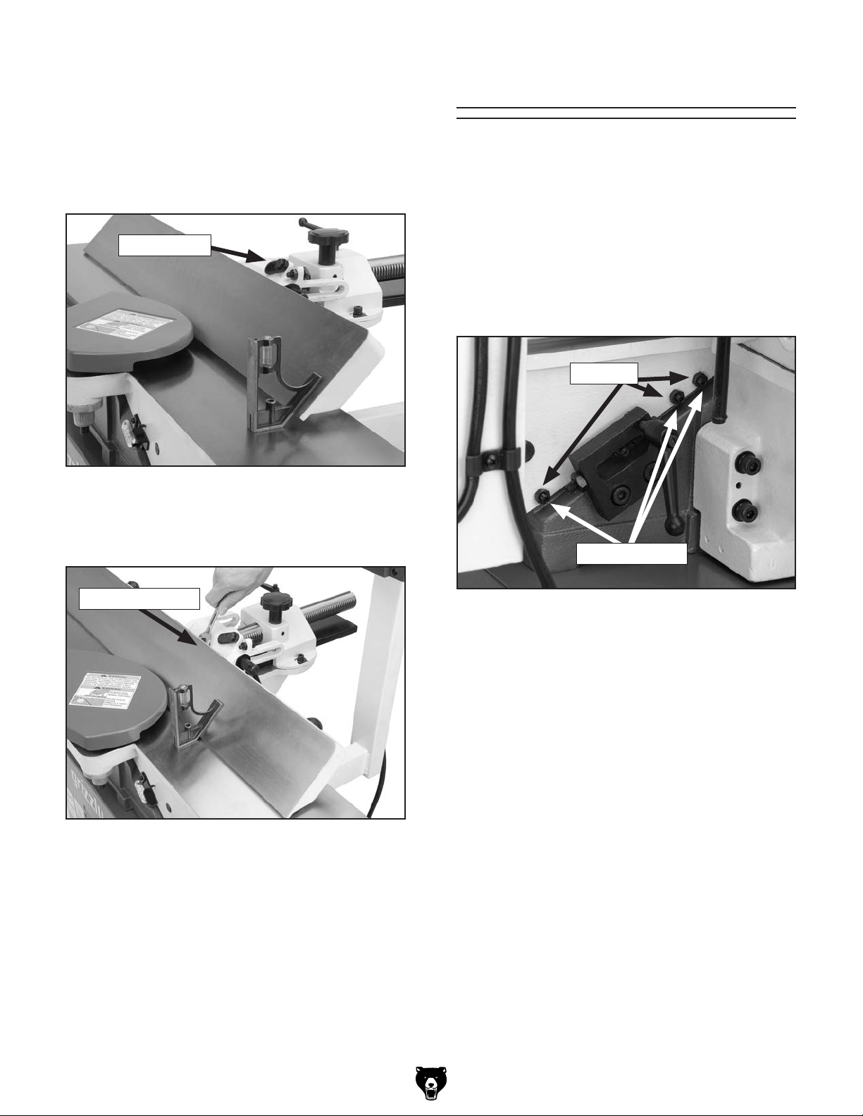
To set the 45˚ outward fence stop:
1. Flip the 90˚ swing stop out of the way as
shown in Figure 76.
2. Using a sliding bevel adjusted to 135˚, adjust
the fence to the 135˚ (45˚ outward) position.
Adjusting Gibs
The function of the table gibs is to eliminate
excessive play in the table movement. The gibs
also control how easy it will be to move the tables
up and down.
Swing Stop
Figure 76. Adjusting fence 45˚ outward.
3. Loosen the jam nut on the 45˚ outward fence
stop bolt (Figure 77).
Fence Stop Bolt
To adjust the table gibs:
1. Using a 10mm wrench, loosen the two outfeed
table gib nuts on the side of the jointer base
(Figure 78).
Gib Nuts
Gib Setscrews
Figure 78. Outfeed table gib controls.
2. Using a 3mm hex wrench, evenly tighten the
gib setscrews a small amount, then check the
table by moving it up and down. Adjust the
setscrews as needed until the friction of the
table movement is balanced between minimal play and ease of movement.
Figure 77. 45˚ outward fence stop jam nut.
4. Adjust the 45˚ outward fence stop bolt until it
makes contact with the back of the fence.
5. Retighten the jam nut loosened in Step 3 and
recheck.
Model G0452/P/Z (Mfg. Since 08/12)
Note: Tighter gibs reduce play but make it
harder to adjust the tables.
3. Repeat Steps 1-2 with the other table.
4. Set the outfeed table height as described in
Setting Outfeed Table Height on Page 26.
-49-
Page 52

These pages are current at the time of printing. However, in the spirit of improvement, we may make changes to the electrical systems of future machines. Compare the manufacture date of your machine to the one
number and manufacture date of your
machine before calling. This information can be found on the main machine label.
SECTION 8: WIRING
stated in this manual, and study this section carefully.
If there are differences between your machine and what is shown in this section, call Technical Support at
(570) 546-9663 for assistance BEFORE making any changes to the wiring on your machine. An updated
wiring diagram may be available. Note: Please gather the serial
Wiring Safety Instructions
SHOCK HAZARD. Working on wiring that is connected to a power source is extremely dangerous.
Touching electrified parts will result in personal
injury including but not limited to severe burns,
electrocution, or death. Disconnect the power
from the machine before servicing electrical components!
MODIFICATIONS. Modifying the wiring beyond
what is shown in the diagram may lead to unpredictable results, including serious injury or fire.
This includes the installation of unapproved aftermarket parts.
WIRE CONNECTIONS. All connections must
be tight to prevent wires from loosening during
machine operation. Double-check all wires disconnected or connected during any wiring task to
ensure tight connections.
CIRCUIT REQUIREMENTS. You MUST follow
the requirements at the beginning of this manual when connecting your machine to a power
source.
WIRE/COMPONENT DAMAGE. Damaged wires
or components increase the risk of serious personal injury, fire, or machine damage. If you notice
that any wires or components are damaged while
performing a wiring task, replace those wires or
components.
MOTOR WIRING. The motor wiring shown in
these diagrams is current at the time of printing
but may not match your machine. If you find this
to be the case, use the wiring diagram inside the
motor junction box.
CAPACITORS/INVERTERS. Some capacitors
and power inverters store an electrical charge for
up to 10 minutes after being disconnected from
the power source. To reduce the risk of being
shocked, wait at least this long before working on
capacitors.
EXPERIENCING DIFFICULTIES. If you are experiencing difficulties understanding the information
included in this section, contact our Technical
Support at (570) 546-9663.
The photos and diagrams
included in this section are
best viewed in color. You
can view these pages in
color at www.grizzly.com.
-50-
Model G0452/P/Z (Mfg. Since 08/12)
Page 53
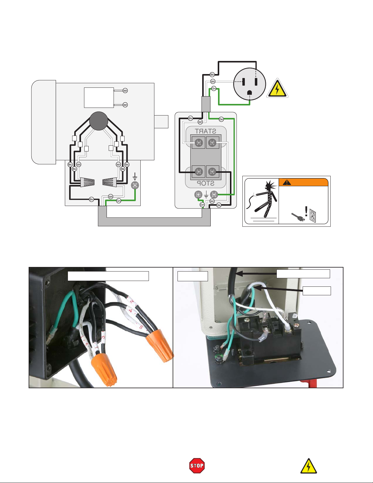
MOTOR
START
STOP
Start
Capacitor
200MFD
125VAC
Wiring Diagram
Black
Hot
White
Neutral
Green
Ground
5-15 Plug
(viewed from behind)
110 VAC
2
4
8
1
3
5
Ground
Electrical Components
Motor Junction Box
Ground
Switch
SWITCH
(viewed from behind)
WARNING!
SHOCK HAZARD!
Disconnect power
before working on
wiring.
to Power Source
to Motor
v Wiring Diagram
Model G0452/P/Z (Mfg. Since 08/12)
READ ELECTRICAL SAFETY
ON PAGE 50!
-51-
Page 54
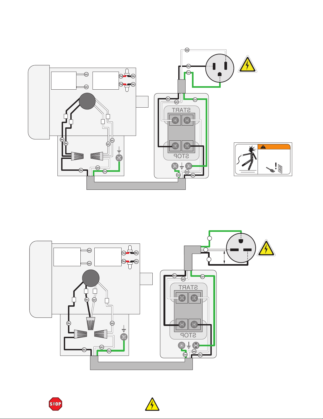
START
STOP
G0452Z 120V Wiring Diagram
START
STOP
Neutral
Hot
Start
Capacitor
300MFD
125VAC
2
4
Run
Capacitor
40MFD
250VAC
1
3
MOTOR
Ground
SWITCH
120 VAC
5-15 Plug
(viewed from behind)
Ground
Ground
G0452Z 240V Wiring Diagram
WARNING!
SHOCK HAZARD!
Disconnect power
before working on
wiring.
Start
Capacitor
300MFD
125VAC
Ground
Run
Capacitor
40MFD
250VAC
MOTOR
Gn
Hot
Wt
220
Bk
VAC
Hot
G
240 VAC
6-15 Plug
(As Recommended)
3 2
4
1
Ground
Ground
SWITCH
(viewed from behind)
-52-
READ ELECTRICAL SAFETY
ON PAGE 50 !
Model G0452/P/Z (Mfg. Since 08/12)
Page 55

17
Please Note: We do our best to stock replacement parts whenever possible, but we cannot guarantee that all parts shown here
are available for purchase. Call (800) 523 - 4777 or visit our online parts store at www.grizzly.com to check for availability.
18
87
86
19
21
262-2
262-1
27
28
29
262-3
30
SECTION 9: PARTS
Table
Cutterhead For Models G0452/P
10
4
5
6
14
15
11
16
31
35
36
37
22
23
24
38
262
25
26
50A
7
8
9
3
1
2
12
13
Spiral Cutterhead
For Model G0452Z
9
1
12
13
2V2
3
81
82
83
32
33
34
70
84
85
10
4
5
6
7
11V2
14
15
16
74
73
72
71
68
229A
230A
75A-6
75A-7
75A-1
39
40
41
42
43
76A
75A-2
75A-3
75A-4
80A
75A-5V2
78A
79A
75A
44
45
46
47
48
49
54
55
56
57
58
59
64
65
69
60
61
66
62
63
67
Model G0452/P/Z (Mfg. Since 08/12)
-53-
Page 56

G0452 Table
REF PART # DESCRIPTION REF PART # DESCRIPTION
1 P0452001 GIB 50A P0452050A TABLE ASSY W/BASE
1 P0452Z001 DRIVER BIT TORX T20 54 P0452054 CAP SCREW M8-1.25 X 15
2 P0452002 KNIVES 6 X 5/8 X 1/8 3-PC SET 55 P0452055 LOCK WASHER 8MM
2V2 P0452Z002V2 INDEXABLE CARBDE INSERT 10PK 56 P0452056 PIVOT ARM BRACKET
3 P0452003 GIB SCREW 57 P0452057 CAPTIVE PIN
3 P0452Z003 INSERT SCREW TORX T20 M6-1 X 15 58 P0452058 EXT RETAINING RING 5MM
4 P0452004 CUTTERHEAD PULLEY 59 P0452059 LEVER HUB
5 P0452005 RIGHT PILLOW BLOCK 60 P0452060 PIVOT LINK
6 P0452006 BALL BEARING 6203-2RS 61 P0452061 PIVOT LINK STEP BOLT
7 P0452007 KEY 5 X 5 X 30 62 P0452062 SET SCREW M8-1.25 X 8
8 P0452008 SET SCREW M5-.8 X 12 63 P0452063 HEX NUT M12-1.75
9 P0452009 CUTTERHEAD NUT 64 P0452064 INFEED PIVOT SHAFT
9 P0452Z009 L-WRENCH TORX T20 65 P0452065 E-CLIP 12MM
10 P0452010 SET SCREW M6-1 X 10 66 P0452066 LEVER ROD
11 P0452011 CUTTERHEAD 6" 3-KNIFE 67 P0452067 HANDLE
11V2 P0452Z011V2 SPIRALCUTTERHEAD 6" V2.04.15 68 P0452068 DUST CHUTE
12 P0452012 BALL BEARING 6202-2RS 69 P0452069 SEAL
13 P0452013 LEFT PILLOW BLOCK 70 P0452070 CLAMP PLATE
14 P0452014 STUD-DE M10-1.5 X 100, 24 71 P0452071 HEX NUT M8-1.25
15 P0452015 LOCK WASHER 10MM 72 P0452072 SET SCREW M8-1.25 X 25
16 P0452016 HEX NUT M10-1.5 73 P0452073 CAP SCREW M8-1.25 X 16
17 P0452017 BUTTON HD CAP SCR M6-1 X 12 74 P0452074 LOCK LEVER
18 P0452018 FLAT WASHER 6MM 75 P0452075 SWITCH MOUNTING BRACKET V1.03.05
19 P0452019 HANDLE 75A P0452075A CONTROL PEDESTAL ASSY V2.07.07
21 P0452021 HANDWHEEL 75A-1 P0452075A-1 PEDESTAL ARM V2.07.07
22 P0452022 SET SCREW M6-1 X 6 75A-2 P0452075A-2 SWITCH BOX V2.07.07
23 P0452023 LOCK COLLAR 75A-3 P0452075A-3 STRAIN RELIEF 13.5MM V2.07.07
24 P0452024 FLAT WASHER 12MM 75A-4 P0452075A-4 FLANGE BOLT M6-1 X 16
25 P0452025 FLAT WASHER 12MM 75A-5 P0452075A-5 POWER CORD 14G 3W 72" 5-15P
26 P0452026 LEADSCREW 75A-6 P0452075A-6 SWITCH CORD
27 P0452027 LEADSCREW BRACKET 75A-7 P0452075A-7 MOTOR CORD
28 P0452028 LOCK WASHER 8MM 76 P0452076 STRAIN RELIEF V1.03.05
29 P0452029 CAP SCREW M8-1.25 X 50 76A P0452076A STRAIN RELIEF V2.07.07
30 P0452030 PUSH BLOCK 77 P0452077 BUTTON HD CAP SCR M5-.8 X 12
31 P0452031 LOCK HANDLE 78 P0452078 CAP SCREW M10-1.5 X 25
32 P0452032 HEX NUT M6-1 78A P0452078A CAP SCREW M8-1.25 X 25
33 P0452033 SET SCREW M6-1 X 25 79 P0452079 LOCK WASHER 10MM
34 P0452034 TABLE GIB 79A P0452079A LOCK WASHER 8MM
35 P0452035 CUTTERHEAD GUARD LABEL 80 P0452080 FLAT WASHER 10MM
36 P0452036 CUTTERHEAD GUARD 80A P0452080A FLAT WASHER 8MM
37 P0452037 POST W/SLOT 81 P0452081 HEX WRENCH 8MM
38 P0452038 SET SCREW M3-.5 X 10 82 P0452082 HEX WRENCH 6MM
39 P0452039 SPACER 83 P0452083 HEX WRENCH 4MM
40 P0452040 INFEED TABLE STOP 84 P0452084 HEX WRENCH 3MM
41 P0452041 POINTER 85 P0452085 HEX WRENCH 2.5MM
42 P0452042 FLAT WASHER 4MM 86 P0452086 WRENCH 8 X 10MM OPEN-END
43 P0452043 BUTTON HD CAP SCR M4-.7 X 16 87 P0452087 WRENCH 12 X 14MM OPEN-END
44 P0452044 ROLL PIN 4 X 20 229A P0452229A SWITCH PLATE V2.07.07
45 P0452045 END PLATE 230A P0452230A START/STOP SWITCH KEDU HY56 V2.07.07
46 P0452046 TORSION SPRING 262 P0452262 KNIFE SETTING JIG ASSEMBLY
47 P0452047 SPRING HOUSING 262-1 P0452262-1 KNIFE JIG ROD
48 P0452048 RETAINER 262-1 P0452262-1 KNIFE JIG ROD
49 P0452049 BUTTON HD CAP SCR M4-.7 X 16 262-3 P0452262-3 E-CLIP 9MM
-54-
Model G0452/P/Z (Mfg. Since 08/12)
Page 57
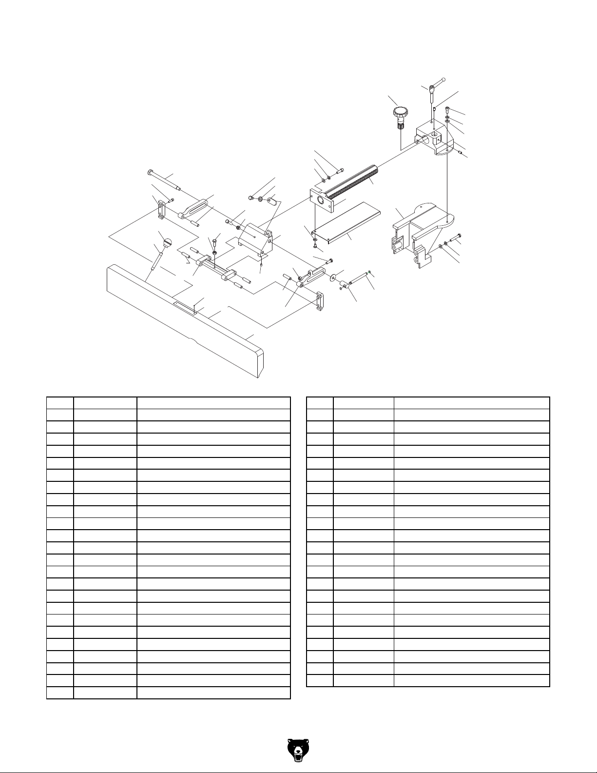
G0452 Fence
112
111
89
90
110
105
104
109 99
108
107
106
131
130
103
102
97
88
94
93
101
100
98
95
114
118
117
116
96
113
119-1
115
92
91
128
119
132
133
121
129
127
126
125
124
123
122
120
134
135
REF PART # DESCRIPTION REF PART # DESCRIPTION
88 P0452088 FENCE 113 P0452113 PHLP HD SCR M6-1 X 12
89 P0452089 LEVER ROD 114 P0452114 LOCK WASHER 6MM
90 P0452090 BALL KNOB 115 P0452115 FENCE CUTTERHEAD GUARD
91 P0452091 HANDLE HUB 116 P0452116 FLAT WASHER 8MM
92 P0452092 FLAT WASHER 4MM 117 P0452117 LOCK WASHER 8MM
93 P0452093 RIGHT BRACKET 118 P0452118 CAP SCREW M8-1.25 X 25
94 P0452094 DOWEL PIN 119 P0452119 FENCE RAM
95 P0452095 HEX NUT M8-1.25 119-1 P0452119-1 RAM PLATE
96 P0452096 HEX BOLT M8-1.25 X 25 120 P0452120 CAP SCREW M8-1.25 X 60
97 P0452097 SET SCREW M6-1 X 10 121 P0452121 FENCE SUPPORT BRACKET
98 P0452098 FENCE BRACKET 122 P0452122 SET SCREW M8-1.25 X 12
99 P0452099 ANGLE STOP 123 P0452123 RAM BRACKET
100 P0452100 FLAT WASHER 8MM 124 P0452124 FLAT WASHER 8MM
101 P0452101 SHOULDER BOLT M8-1.25 X 15 125 P0452125 LOCK WASHER 8MM
102 P0452102 HEX NUT M8-1.25 126 P0452126 CAP SCREW M8-1.25 X 20
103 P0452103 HEX BOLT M8-1.25 X 25 127 P0452127 SET SCREW M8-1.25 X 12
104 P0452104 FENCE SUPPORT 128 P0452128 KNOB BOLT
105 P0452105 DOWEL PIN 129 P0452129 LOCK LEVER
106 P0452106 HEX NUT M8-1.25 130 P0452130 FENCE WARNING LABEL
107 P0452107 HEX BOLT M8-1.25 X 25 131 P0452131 ALUMINUM RIVET
108 P0452108 DOWEL PIN 132 P0452132 O-RING 5.8 X 1.9 P6
109 P0452109 LEFT BRACKET 133 P0452133 LOCK LEVER BAR
110 P0452110 FENCE BRACKET BOLT 134 P0452134 LOCK WASHER 8MM
111 P0452111 REAR CLAMP 135 P0452135 FLAT WASHER 8MM
112 P0452112 CAP SCREW M6-1 X 20
Model G0452/P/Z (Mfg. Since 08/12)
-55-
Page 58

G0452 Base
224-5
224-9
216
217
218
212
219
220
211
221
210
222
223
228
227
226
224-3
224-1
225
224-4
224-2
224-7
224-8
224-6
224
-56-
215
214
213
202
201A
203
204
205
206
254A
207
209
208
248
253
254
252
234
249
235
251
250
241
236
247
237
246
238
245
242
239
244
243
240
Model G0452/P/Z (Mfg. Since 08/12)
Page 59

G0452 Base
234
235
236
P0452236 SHAFT 12MM
237
P0452237 HEX BOLT M8-1.25 X 50
238
P0452238 FLAT WASHER 8MM
239
P0452239 HEX NUT M10-1.5
240
241
P0452241 HEX NUT M8-1.25
242
P0452242 LOCK NUT M12-1.75
243
P0452243 FLAT WASHER 8MM
244
P0452244 HEX BOLT M8-1.25 X 100
245
246
247
P0452247 BALL BEARING 6202-2RS
248
P0452248 INT RETAINING RING 35MM
249
P0452249 TROLLEY WHEEL SLEEVE
250
251
252
P0452252 HEX BOLT M10-1.5 X 55
253
P0452253 BRACKET
254
P0452254 PEDAL
254A
P0452254A PEDAL ASSEMBLY
REF PART # DESCRIPTION REF PART # DESCRIPTION
201A P0452201A WHITE CABINET V2.08.07 224-7 P0452224-7 BALL BEARING 6204ZZ
202 P0452202 HEX NUT M8-1.25 224-8 P0452224-8 CENTRIFUGAL SWITCH 20MM-3450
203 P0452203 FLAT WASHER 8MM 224-9 P0452224-9 CONTACT PLATE 20MM
204 P0452204 UNIVERSAL WHEEL 78MM DIA 225 P0452225 KEY 5 X 5 X 30
205 P0452205 SLEEVE 226 P0452226 V-BELT A38
206 P0452206 CAP SCREW M5-.8 X 10 227 P0452227 MOTOR PULLEY
207 P0452207 STRAIN RELIEF 228 P0452228 SET SCREW M6-1 X 6
208 P0452208 HEX NUT 3/8-16
209 P0452209 RUBBER FOOT
210 P0452210 HEX NUT 5/16-18
211 P0452211 FLAT WASHER 10MM
212 P0452212 MOTOR MOUNT BRACKET
213 P0452213 DUST CHUTE
214 P0452214 FLAT WASHER 3MM
215 P0452215 BUTTON HD CAP SCR M5-.8 X 16
216 P0452216 BUTTON HD CAP SCR M5-.8 X 16
217 P0452217 FLAT WASHER 5MM
218 P0452218 CABINET REAR COVER
219 P0452219 HEX BOLT 5/16-18 X 3/4
220 P0452220 HEX NUT 5/16-18
221 P0452221 CARRIAGE BOLT 5/16-18 X 1
222 P0452222 LOCK WASHER 10MM
223 P0452223 CAP SCREW M10-1.5 X 20
224 P0452224 MOTOR 1HP 120V 1-PH
224-1 P0452224-1 FAN COVER
224-2 P0452224-2 MOTOR FAN
224-3 P0452224-3 CAPACITOR COVER
224-4 P0452224-4 S CAPACITOR 200M 125V 1-1/2 X 2-3/4
224-5 P0452224-5 JUNCTION BOX
224-6 P0452224-6 BALL BEARING 6204ZZ
P0452234 EXT RETAINING RING 9MM
P0452235 FLAT WASHER 12MM
P0452240 FLAT WASHER 10MM
P0452245 TROLLEY WHEEL BOLT
P0452246 TROLLEY WHEEL
P0452250 TROLLEY UNIVERSAL KIT
P0452251 FLAT WASHER 10MM
Model G0452/P/Z (Mfg. Since 08/12)
-57-
Page 60

G0452 Labels
REF PART # DESCRIPTION REF PART # DESCRIPTION
255V2
P0452255V2 MACHINE ID LABEL CSA V2.08.12
260
P0452260 GRIZZLY NAMEPLATE, SMALL
256
P0452256 SAFETY GLASSES LABEL
261
P0452261 ELECTRICITY LABEL
257
P0452257 READ MANUAL LABEL
263
P0452263 DISCONNECT LABEL
258
P0452258 GRIZZLY.COM LABEL 9-3/4 X 2
264
P0452264 EAR PROTECTION LABEL
259
P0452259 MODEL NUMBER LABEL
258
260
264
261
256
257
255V2
263
259
-58-
Model G0452/P/Z (Mfg. Since 08/12)
Page 61

WARRANTY CARD
Name _____________________________________________________________________________
Street _____________________________________________________________________________
City _______________________ State _________________________ Zip _____________________
Phone # ____________________ Email _________________________________________________
Model # ____________________ Order # _______________________ Serial # __________________
The following information is given on a voluntary basis. It will be used for marketing purposes to help us develop
better products and services. Of course, all information is strictly confidential.
1. How did you learn about us?
____ Advertisement ____ Friend ____ Catalog
____ Card Deck ____Website ____ Other:
2. Which of the following magazines do you subscribe to?
____ Cabinetmaker & FDM
____ Family Handyman
____ Hand Loader
____ Handy
____ Home Shop Machinist
____ Journal of Light Cont.
____ Live Steam
____ Model Airplane News
____ Old House Journal
____ Popular Mechanics
3. What is your annual household income?
____ $20,000-$29,000 ____$30,000-$39,000 ____ $40,000-$49,000
____ $50,000-$59,000 ____$60,000-$69,000 ____ $70,000+
CUT ALONG DOTTED LINE
4. What is your age group?
____ 20-29 ____ 30-39 ____ 40-49
____ 50-59 ____ 60-69 ____ 70+
5. How long have you been a woodworker/metalworker?
____ 0-2 Years ____ 2-8 Years ____ 8-20 Years ____20+ Years
6. How many of your machines or tools are Grizzly?
____ 0-2 ____ 3-5 ____ 6-9 ____ 10+
____ Popular Science
____ Popular Woodworking
____ Precision Shooter
____ Projects in Metal
____ RC Modeler
____ Rie
____ Shop Notes
____ Shotgun News
____ Today’s Homeowner
____ Wood
____ Wooden Boat
____ Woodshop News
____ Woodsmith
____ Woodwork
____ Woodworker West
____ Woodworker’s Journal
____ Other:
7. Do you think your machine represents a good value? _____Yes _____No
8. Would you recommend Grizzly Industrial to a friend? _____ Yes _____No
9. Would you allow us to use your name as a reference for Grizzly customers in your area?
Note: We never use names more than 3 times. _____ Yes _____No
10. Comments: _____________________________________________________________________
_________________________________________________________________________________
_________________________________________________________________________________
_________________________________________________________________________________
Page 62

FOLD ALONG DOTTED LINE
FOLD ALONG DOTTED LINE
Place
Stamp
Here
GRIZZLY INDUSTRIAL, INC.
P.O. BOX 2069
BELLINGHAM, WA 98227-2069
Send a Grizzly Catalog to a friend:
Name_______________________________
Street_______________________________
City______________State______Zip______
TAPE ALONG EDGES--PLEASE DO NOT STAPLE
Page 63

WARRANTY AND RETURNS
We shall in no event be liable for death, injuries to persons or property or for incidental, contingent, special,
WARRANTY AND RETURNS
Grizzly Industrial, Inc. warrants every product it sells for a period of 1 year to the original purchaser from
the date of purchase. This warranty does not apply to defects due directly or indirectly to misuse, abuse,
negligence, accidents, repairs or alterations or lack of maintenance. This is Grizzly’s sole written warranty
and any and all warranties that may be implied by law, including any merchantability or fitness, for any particular purpose, are hereby limited to the duration of this written warranty. We do not warrant or represent
that the merchandise complies with the provisions of any law or acts unless the manufacturer so warrants.
In no event shall Grizzly’s liability under this warranty exceed the purchase price paid for the product and
any legal actions brought against Grizzly shall be tried in the State of Washington, County of Whatcom.
or consequential damages arising from the use of our products.
To take advantage of this warranty, contact us by mail or phone and give us all the details. We will then
issue you a “Return Number,’’ which must be clearly posted on the outside as well as the inside of the
carton. We will not accept any item back without this number. Proof of purchase must accompany the
merchandise.
The manufacturers reserve the right to change specifications at any time because they constantly strive to
achieve better quality equipment. We make every effort to ensure that our products meet high quality and
durability standards and we hope you never need to use this warranty.
Please feel free to write or call us if you have any questions about the machine or the manual.
Thank you again for your business and continued support. We hope to serve you again soon.
Page 64

 Loading...