


MODEL G0452 Series
6" x 46" MOBILE JOINTER
OWNER'S MANUAL
(Models G0452, G0452P, G0452Z)
(For models manufactured since 08/12)
COPYRIGHT © JUNE, 2005 BY GRIZZLY INDUSTRIAL, INC. REVISED DECEMBER, 2017 (HE)
WARNING: NO PORTION OF THIS MANUAL MAY BE REPRODUCED IN ANY SHAPE
OR FORM WITHOUT THE WRITTEN APPROVAL OF GRIZZLY INDUSTRIAL, INC.
#PC7250 PRINTED IN CHINA

This manual provides critical safety instructions on the proper setup,
operation, maintenance, and service of this machine/tool. Save this
document, refer to it often, and use it to instruct other operators.
Failure to read, understand and follow the instructions in this manual
may result in fire or serious personal injury—including amputation,
electrocution, or death.
The owner of this machine/tool is solely responsible for its safe use.
This responsibility includes but is not limited to proper installation in
a safe environment, personnel training and usage authorization,
proper inspection and maintenance, manual availability and comprehension, application of safety devices, cutting/sanding/grinding tool
integrity, and the usage of personal protective equipment.
The manufacturer will not be held liable for injury or property damage
from negligence, improper training, machine modifications or misuse.
Some dust created by power sanding, sawing, grinding, drilling, and
other construction activities contains chemicals known to the State
of California to cause cancer, birth defects or other reproductive
harm. Some examples of these chemicals are:
• Lead from lead-based paints.
• Crystalline silica from bricks, cement and other masonry products.
• Arsenic and chromium from chemically-treated lumber.
Your risk from these exposures varies, depending on how often you
do this type of work. To reduce your exposure to these chemicals:
Work in a well ventilated area, and work with approved safety equipment, such as those dust masks that are specially designed to filter
out microscopic particles.

Table of Contents
INTRODUCTION ............................................... 2
Machine Description ...................................... 2
Contact Info.................................................... 2
Manual Accuracy ........................................... 2
Identification ................................................... 3
Machine Data Sheet ...................................... 4
SECTION 1: SAFETY ....................................... 7
Safety Instructions for Machinery .................. 7
SECTION 2: POWER SUPPLY ...................... 10
Availability ......................................................... 10
Full-Load Current Rating .................................. 10
Circuit Information ............................................. 10
Grounding Requirements .................................. 10
Circuit Requirements for G0452/P ....................11
G0452Z Circuit Requirements for 120V ........... 11
G0452Z Circuit Requirements for 240V ........... 12
Voltage Conversion (G0452Z Only) .................. 12
Extension Cords ................................................ 13
SECTION 3: SETUP ....................................... 14
Unpacking .................................................... 14
Needed for Setup ......................................... 14
Inventory ...................................................... 15
Cleanup ........................................................ 16
Site Considerations ...................................... 17
Locking Foot Pedal ...................................... 18
Mounting Jointer .......................................... 19
V-Belt ........................................................... 20
Carriage Mounting Bracket .......................... 21
Fence Carriage Assembly ........................... 22
Fence Assembly .......................................... 22
Cutterhead Guard ........................................ 23
Dust Port ...................................................... 24
Dust Collection ............................................. 24
Power Switch ............................................... 25
Handwheels ................................................. 25
Infeed Table Lever ....................................... 26
Setting Outfeed Table Height ...................... 26
For Models G0452/G0452P .............................. 26
For Model G0452Z ............................................ 27
Test Run ...................................................... 28
Recommended Adjustments ........................ 28
SECTION 4: OPERATIONS ........................... 29
Operation Overview ..................................... 29
Infeed Table Adjustment .............................. 30
Stock Inspection and Requirements ............ 31
Squaring Stock............................................. 32
Surface Planing............................................ 32
Edge Jointing ............................................... 33
Bevel Cutting................................................ 34
Rabbet Cutting ............................................. 35
SECTION 5: ACCESSORIES ......................... 37
SECTION 6: MAINTENANCE ......................... 41
Schedule ...................................................... 41
V-Belt ........................................................... 41
Cleaning ....................................................... 41
Unpainted Cast Iron ..................................... 41
Lubrication ................................................... 41
SECTION 7: SERVICE ................................... 42
Troubleshooting ........................................... 42
Motor & Machine Operation .............................. 42
Table ................................................................. 43
Cutting ............................................................... 43
About Service............................................... 44
Inspecting Knives ......................................... 44
G0452/G0452P Setting Knives .................... 44
G0452Z Replacing Carbide Inserts ............. 46
Calibrating Depth Scale ............................... 47
Setting Fence Stops .................................... 48
Adjusting Gibs .............................................. 49
SECTION 8: WIRING ...................................... 50
Wiring Safety Instructions ............................ 50
Wiring Diagram ............................................ 51
Electrical Components ................................. 51
Motor Junction Box ........................................... 51
Switch ...............................................................51
SECTION 9: PARTS ....................................... 53
Table ............................................................ 53
G0452 Fence ............................................... 55
G0452 Base ................................................ 56
WARRANTY AND RETURNS ........................ 61

INTRODUCTION
We are proud to provide a high-quality owner’s
manual with your new machine!
We
instructions, specifications, drawings, and photographs
in this manual. Sometimes we make mistakes, but
our policy of continuous improvement also means
that
you receive is
slightly different than shown in the manual
If you find this to be the case, and the difference
between the manual and machine leaves you
confused or unsure about something
check our
website for an updated version. W
current
manuals and
on our web-
site at
Alternatively, you can call our Technical Support
for help. Before calling, make sure you write down
the
from
the machine ID label (see below). This information
is required for us to provide proper tech support,
and it helps us determine if updated documentation is available for your machine.
We stand behind our machines. If you have
any questions or need help, use the information
below to contact us. Before contacting, please get
the serial number and manufacture date of your
machine. This will help us help you faster.
We want your feedback on this manual. What did
you like about it? Where could it be improved?
Please take a few minutes to give us feedback.
Machine Description
We are proud to offer the Grizzly Jointer G0452,
G0452P and G0452Z Models. The G0452P Model
offers the same outstanding quality as the G0452
only produced in Polar Bear white. The Model
G0452Z features a 1.5 H.P. motor and spiral
cutterhead, whereas the G0452 and G0452P
Models feature a 1 H.P. with a 3 knife cutterhead.
When used according to the guidelines set forth in
this manual, you can expect years of trouble-free,
enjoyable operation and proof of Grizzly’s commitment to customer satisfaction.
A number of accessories for jointer Models G0452/
G0452P/G0452Z are available through the Grizzly
catalog.
Contact Info
Manual Accuracy
made every effort to be exact with the
sometimes the machine
.
,
e post
manual updates for free
www.grizzly.com.
Manufacture Date and Serial Number
Grizzly Technical Support
1203 Lycoming Mall Circle
Muncy, PA 17756
Phone: (570) 546-9663
Email: techsupport@grizzly.com
Grizzly Documentation Manager
P.O. Box 2069
Bellingham, WA 98227-2069
Email: manuals@grizzly.com
Manufacture Date
Serial Number
-2-
Model G0452/P/Z (Mfg. Since 08/12)
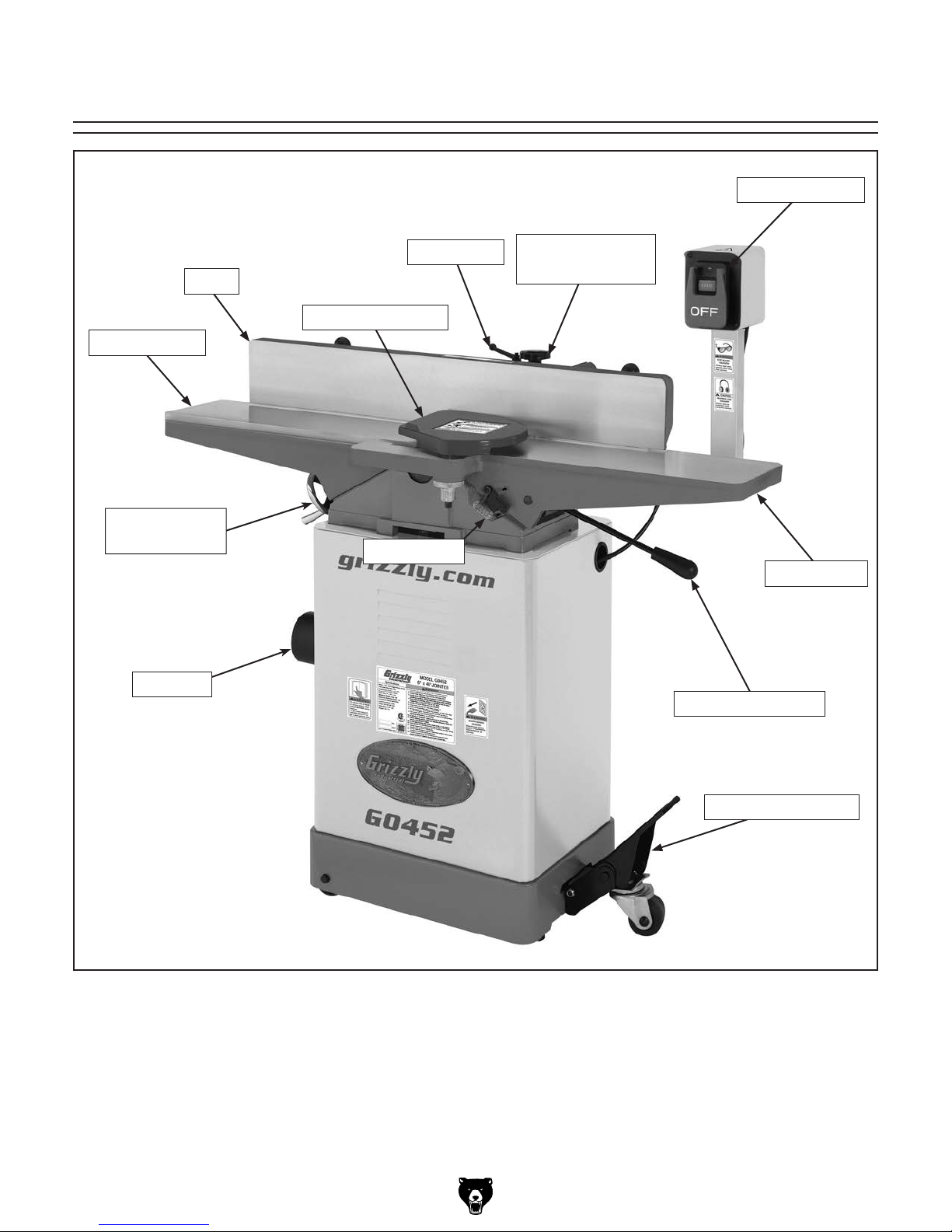
Identification
ON/OFF Switch
Fence
Outfeed Table
Outfeed Table
Handwheel
Dust Port
Fence Lock
Cutterhead Guard
Depth Scale
Fence
Adjustment Knob
Infeed Table
Infeed Table Lever
Model G0452/P/Z (Mfg. Since 08/12)
Locking Foot Pedal
-3-

Customer Service #: (570) 546-9663 · To Order Call: (800) 523-4777 · Fax #: (800) 438-5901
MODEL G0452, G0452P, G0452Z
6" x 46" Jointer
Model Number G0452 G0452P G0452Z
Product Dimensions
Weight 257 lbs.
Width (side-to-side)/Depth (frontto-back)/Height
Foot Print (Width/Depth) 18" x 13-
46" x 27-
Shipping Dimensions Box 1
Type Cardboard
Weight 174 lbs.
Width (side-to-side)/Depth (frontto-back)/Height
49" x 21" x 15"
Shipping Dimensions Box 2
Type Cardboard
Weight 94
Width (side-to-side)/Depth (frontto-back)/Height
21" x 16" x 29"
Electrical
Power Requirement 120V, Single-Phase, 60 Hz 120V/240V, Single-Phase,
Full-Load Current Rating 13A 15A at 240V/7.5A at 120V
Switch Push Button with Oversized OFF Button
Switch Voltage 120V 120V/240V
Cord Length 6 ft
Cord Gauge 14 AWG
Recommended Circuit Size at
120V
Recommended Circuit Size at
240V
Plug Included Yes
Included Plug Type for 120V NEMA 5-15 for 120V
Recommended Plug Type for
Rewired 240V Operation (not
included)
N/A 15A
N/A NEMA 6-15 for 240V
1
15A
⁄2" x 49"
1
⁄2"
60 Hz
-4-
Model G0452/P/Z (Mfg. Since 08/12)

Model Number G0452 G0452P G0452Z
Main Motor
Type TEFC Capacitor Start Induction
1
Horsepower 1 HP 1
Voltage 120V 120V/240V
Phase Single
Amps 13A at 120V 15A/7.5A
Speed 3450 RPM
Cycle 60 Hz
Power Transfer V-Belt Drive
Bearings Sealed and Lubricated Ball Bearings
Main Specifications:
Cutting Capacites
Bevel Jointing Left and Right 45 deg.
Maximum Width of Cut 6 in.
1
Maximum Depth of Cut
⁄8 in.
Minimum Workpiece Length 8 in.
1
Minimum Workpiece Thickness
Maximum Rabbeting Depth
⁄2 in.
1
⁄2 in.
Number of Cuts Per Minute 14,400 19,200
Fence Information
Fence Length 35 in.
1
Fence Width 1
⁄2 in.
Fence Height 5 in.
Fence Stop 45, 90, and 135 deg.
Cutterhead Information
Cutterhead Type 3 Knife Spiral
1
Cutterhead Diameter 2
⁄2 in.
Cutterhead Speed 4800 RPM
Knife Information for G0452/G0452P
Number of Knives 3 N/A
Knife Type HSS, Single-Sided N/A
Knife Length 6 in. N/A
5
Knife Width
Knife Thickness
⁄8 in. N/A
1
⁄8 in. N/A
Knife Adjustment Jack Screws N/A
Cutter Insert Information for G0452Z
Cutter Insert Type N/A Indexible Carbide
Cutter Insert length N/A 14mm
Cutter Insert Width N/A 14mm
Cutter Insert Thickness N/A 2mm
⁄2 HP
Model G0452/P/Z (Mfg. Since 08/12)
-5-

Model Number G0452 G0452P G0452Z
Table Information
Table Length 46 in.
1
Table Width 7
Table Thickness 1 in.
Floor to Table Height 32
Table Adjustment Type Handwheel/Lever
Table Movement Type Dovetailed Ways
Construction
Body Assembly Cast Iron
Cabinet Pre-Steel Cabinet
Fence Assembly Cast Iron
Guard Die Cast Metal
Table Precision Ground Cast Iron
Paint Powder Coated
Other Information
Number of Dust Ports 1
Dust Port Size 4 in.
Other Specifications
Country of Origin China
Warranty 1 Year
Serial Number Location ID Label
Customer Assembly & Setup
Time
CSA Cerified Yes
⁄2 in.
1
⁄2 in.
1 Hour
-6-
Model G0452/P/Z (Mfg. Since 08/12)

SECTION 1: SAFETY
For Your Own Safety, Read Instruction
Manual Before Operating This Machine
The purpose of safety symbols is to attract your attention to possible hazardous conditions.
This manual uses a series of symbols and signal words intended to convey the level of importance of the safety messages. The progression of symbols is described below. Remember that
safety messages by themselves do not eliminate danger and are not a substitute for proper
accident prevention measures. Always use common sense and good judgment.
Indicates an imminently hazardous situation which, if not avoided,
WILL result in death or serious injury.
Indicates a potentially hazardous situation which, if not avoided,
COULD result in death or serious injury.
Indicates a potentially hazardous situation which, if not avoided,
MAY result in minor or moderate injury. It may also be used to alert
against unsafe practices.
This symbol is used to alert the user to useful information about
NOTICE
proper operation of the machine.
Safety Instructions for Machinery
OWNER’S MANUAL. Read and understand this
owner’s manual BEFORE using machine.
TRAINED OPERATORS ONLY. Untrained operators have a higher risk of being hurt or killed.
Only allow trained/supervised people to use this
machine. When machine is not being used, disconnect power, remove switch keys, or lock-out
machine to prevent unauthorized use—especially
around children. Make your workshop kid proof!
DANGEROUS ENVIRONMENTS. Do not use
machinery in areas that are wet, cluttered, or have
poor lighting. Operating machinery in these areas
greatly increases the risk of accidents and injury.
MENTAL ALERTNESS REQUIRED. Full mental
alertness is required for safe operation of machinery. Never operate under the influence of drugs or
alcohol, when tired, or when distracted.
ELECTRICAL EQUIPMENT INJURY RISKS. You
can be shocked, burned, or killed by touching live
electrical components or improperly grounded
machinery. To reduce this risk, only allow qualified
service personnel to do electrical installation or
repair work, and always disconnect power before
accessing or exposing electrical equipment.
DISCONNECT POWER FIRST.
nect machine from power supply BEFORE making
adjustments, changing tooling, or servicing machine.
This prevents an injury risk from unintended startup
or contact with live electrical components.
EYE PROTECTION. Always wear ANSI-approved
safety glasses or a face shield when operating or
observing machinery to reduce the risk of eye
injury or blindness from flying particles. Everyday
eyeglasses are NOT approved safety glasses.
Always discon-
Model G0452/P/Z (Mfg. Since 08/12)
-7-

WEARING PROPER APPAREL. Do not wear
clothing, apparel or jewelry that can become
entangled in moving parts. Always tie back or
cover long hair. Wear non-slip footwear to reduce
risk of slipping and losing control or accidentally
contacting cutting tool or moving parts.
HAZARDOUS DUST. Dust created by machinery
operations may cause cancer, birth defects, or
long-term respiratory damage. Be aware of dust
hazards associated with each workpiece material. Always wear a NIOSH-approved respirator to
reduce your risk.
HEARING PROTECTION. Always wear hearing protection when operating or observing loud
machinery. Extended exposure to this noise
without hearing protection can cause permanent
hearing loss.
REMOVE ADJUSTING TOOLS. Tools left on
machinery can become dangerous projectiles
upon startup. Never leave chuck keys, wrenches,
or any other tools on machine. Always verify
removal before starting!
USE CORRECT TOOL FOR THE JOB. Only use
this tool for its intended purpose—do not force
it or an attachment to do a job for which it was
not designed. Never make unapproved modifications—modifying tool or using it differently than
intended may result in malfunction or mechanical
failure that can lead to personal injury or death!
AWKWARD POSITIONS. Keep proper footing
and balance at all times when operating machine.
Do not overreach! Avoid awkward hand positions
that make workpiece control difficult or increase
the risk of accidental injury.
CHILDREN & BYSTANDERS. Keep children and
bystanders at a safe distance from the work area.
Stop using machine if they become a distraction.
GUARDS & COVERS. Guards and covers reduce
accidental contact with moving parts or flying
debris. Make sure they are properly installed,
undamaged, and working correctly BEFORE
operating machine.
FORCING MACHINERY. Do not force machine.
It will do the job safer and better at the rate for
which it was designed.
NEVER STAND ON MACHINE. Serious injury
may occur if machine is tipped or if the cutting
tool is unintentionally contacted.
STABLE MACHINE. Unexpected movement during operation greatly increases risk of injury or
loss of control. Before starting, verify machine is
stable and mobile base (if used) is locked.
USE RECOMMENDED ACCESSORIES. Consult
this owner’s manual or the manufacturer for recommended accessories. Using improper accessories will increase the risk of serious injury.
UNATTENDED OPERATION. To reduce the
risk of accidental injury, turn machine OFF and
ensure all moving parts completely stop before
walking away. Never leave machine running
while unattended.
MAINTAIN WITH CARE. Follow all maintenance
instructions and lubrication schedules to keep
machine in good working condition. A machine
that is improperly maintained could malfunction,
leading to serious personal injury or death.
DAMAGED PARTS. Regularly inspect machine
for damaged, loose, or mis-adjusted parts—or
any condition that could affect safe operation.
Immediately repair/replace BEFORE operating
machine. For your own safety, DO NOT operate
machine with damaged parts!
MAINTAIN POWER CORDS. When disconnecting cord-connected machines from power, grab
and pull the plug—NOT the cord. Pulling the cord
may damage the wires inside. Do not handle
cord/plug with wet hands. Avoid cord damage by
keeping it away from heated surfaces, high traffic
areas, harsh chemicals, and wet/damp locations.
EXPERIENCING DIFFICULTIES. If at any time
you experience difficulties performing the intended operation, stop using the machine! Contact our
Technical Support at (570) 546-9663.
-8-
Model G0452/P/Z (Mfg. Since 08/12)

Additional Safety for Jointers
JOINTER INJURY RISKS. Familiarize yourself
with the main injury risks associated with jointers—always use common sense and good judgement to reduce your risk of injury. Main injury
risks from jointers: amputation/lacerations from
contact with the moving cutterhead, entanglement/crushing injuries from getting caught in moving parts, blindness or eye injury from flying wood
chips, or impact injuries from workpiece kickback.
KICKBACK. Know how to reduce the risk of kickback and kickback-related injuries. “Kickback”
occurs during the operation when the workpiece is
ejected from the machine at a high rate of speed.
Kickback is commonly caused by poor workpiece
selection, unsafe feeding techniques, or improper
machine setup/maintenance. Kickback injuries
typically occur as follows: (1) operator/bystanders
are struck by the workpiece, resulting in impact
injuries (i.e., blindness, broken bones, bruises,
death); (2) operator’s hands are pulled into blade,
resulting in amputation or severe lacerations.
GUARD REMOVAL. Except when rabbeting,
never remove guards during operation or while
connected to power. Always replace guard after
rabbeting. You could be seriously injured if you
accidentally touch the spinning cutterhead or
get entangled in moving parts. Before removing
sawdust, turn jointer OFF and disconnect power
before clearing. Immediately replace guards.
DULL/DAMAGED KNIVES/INSERTS. Only use
sharp, undamaged knives/inserts. Dull, damaged
or rusted knives/inserts increase risk of kickback.
OUTFEED TABLE ALIGNMENT. To reduce the
risk of kickback and personal injuries, keep the
outfeed table even with the knives/inserts at top
dead center (the highest point during rotation).
If the outfeed table is set too low, the workpiece
may rock against the cutterhead. If the table is set
too high, the workpiece may hit the outfeed table
and get stuck over the cutterhead.
INSPECTING STOCK. To reduce the risk of
kickback injuries or machine damage, thoroughly
inspect and prepare the workpiece before cutting.
Verify the workpiece is free of nails, staples, loose
knots or other foreign material. Workpieces with
minor warping should be surface planed first with
the cupped side facing the infeed table.
GRAIN DIRECTION. Jointing against the grain
or end grain increases the required cutting force,
which could produce chatter or excessive chip
out, and lead to kickback.
CUTTING LIMITATIONS. To reduce the risk of
accidental cutterhead contact or kickback, never
perform jointing, planing, or rabbeting cuts on
3
pieces smaller than 8" long,
⁄4" wide, or 1⁄4" thick.
MAXIMUM CUTTING DEPTH. To reduce the risk
1
of kickback, never cut deeper than
⁄8" per pass.
PUSH BLOCKS. To reduce the risk of accidental
cutterhead contact, always use push blocks when
planing materials less than 3" high or wide. Never
pass your hands directly over the cutterhead without a push block.
WORKPIECE SUPPORT. To reduce accidental cutterhead contact and kickback, support
workpiece continuously during operation. Position
and guide workpiece with fence; support long or
wide stock with auxiliary stands.
FEED WORKPIECE PROPERLY. To reduce the
risk of kickback, never start jointer with workpiece
touching cutterhead. Allow cutterhead to reach
full speed before feeding. Never back work toward
the infeed table.
SECURE KNIVES/INSERTS. Loose knives or
improperly set inserts can become dangerous
projectles or cause machine damage. Always verify knives/inserts are secure and properly adjusted before operation. Straight knives should never
1
project more than
⁄8" (0.125 ") from cutterhead
body.
Model G0452/P/Z (Mfg. Since 08/12)
-9-

SECTION 2: POWER SUPPLY
Before installing the machine, consider the availability and proximity of the required power supply
circuit. If an existing circuit does not meet the
requirements for this machine, a new circuit must
be installed. To minimize the risk of electrocution,
fire, or equipment damage, installation work and
electrical wiring must be done by an electrican or
qualified service personnel in accordance with all
applicable codes and standards.
Electrocution, fire, or
equipment damage may
occur if machine is not
correctly grounded and
connected to the power
The full-load current rating is the amperage a
machine draws at 100% of the rated output power.
On machines with multiple motors, this is the
amperage drawn by the largest motor or sum of all
motors and electrical devices that might operate
at one time during normal operations.
The full-load current is not the maximum amount
of amps that the machine will draw. If the machine
is overloaded, it will draw additional amps beyond
the full-load rating.
If the machine is overloaded for a sufficient length
of time, damage, overheating, or fire may result—
especially if connected to an undersized circuit.
To reduce the risk of these hazards, avoid overloading the machine during operation and make
sure it is connected to a power supply circuit that
meets the requirements in the following section.
For your own safety and protection of
Note: The circuit requirements listed in this manual apply to a dedicated circuit—where only one
machine will be running at a time. If this machine
will be connected to a shared circuit where multiple machines will be running at the same time,
consult a qualified electrician to ensure that the
circuit is properly sized for safe operation.
A power supply circuit includes all electrical
equipment between the breaker box or fuse panel
in the building and the machine. The power supply circuit used for this machine must be sized to
safely handle the full-load current drawn from the
machine for an extended period of time. (If this
machine is connected to a circuit protected by
fuses, use a time delay fuse marked D.)
Improper connection of the equipment-grounding
wire can result in a risk of electric shock. The
wire with green insulation (with or without yellow
stripes) is the equipment-grounding wire. If repair
or replacement of the power cord or plug is necessary, do not connect the equipment-grounding
wire to a live (current carrying) terminal.
Check with a qualified electrician or service personnel if you do not understand these grounding
requirements, or if you are in doubt about whether
the tool is properly grounded. If you ever notice
that a cord or plug is damaged or worn, disconnect it from power, and immediately replace it with
a new one.
This machine MUST be grounded. In the event
of certain malfunctions or breakdowns, grounding
reduces the risk of electric shock by providing a
path of least resistance for electric current.
Availability
supply.
Full-Load Current Rating
Circuit Information
property, consult an electrician if you are
unsure about wiring practices or electrical
codes in your area.
G0452/P Current Rating at 120V ....... 13 Amps
G0452Z Current Rating at 120V ........ 15 Amps
G0452Z Current Rating at 240V ....... 7. 5 Amps
-10 -
Grounding Requirements
Model G0452/P/Z (Mfg. Since 08/12)
G045/P/Z Circuit Requirements for
it will not fit the outlet, have a qualified
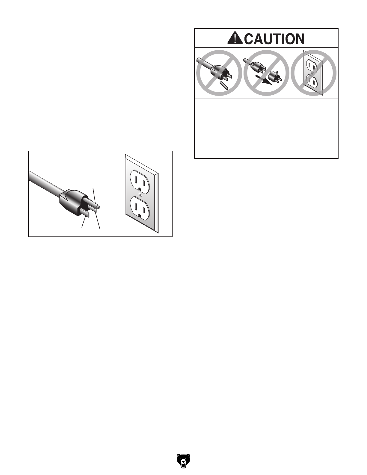
This machine is equipped with a power cord that
has an equipment-grounding wire and a ground
ing plug (similar to the figure below). The plug
must only be inserted into a matching receptacle
(outlet) that is properly installed and grounded in
accordance with all local codes and ordinances.
120V Operation (Prewired)
Nominal Voltage ........................................120V
Cycle .......................................................... 60 Hz
Phase ........................................... Single-Phase
Power Supply Circuit ......................... 15 Amps
Plug/Receptacle ............................. NEMA 5-15
GROUNDED
5-15 RECEPTACLE
Grounding Prong
5-15 PLUG
Neutral Hot
Figure 2. Typical 5-15 plug and receptacle.
-
SHOCK HAZARD!
Two-prong outlets do not meet the grounding
requirements for this machine. Do not modify
or use an adapter on the plug provided—if
electrician install the proper outlet with a
verified ground.
Model G0452/P/Z (Mfg. Since 08/12)
-11-

We do not recommend using an extension cord
with this machine.
cord, only use it if absolutely necessary and only
on a temporary basis.
Extension cords cause voltage drop, which may
damage electrical components and shorten motor
life. Voltage drop increases as the extension cord
size gets longer and the gauge size gets smaller
(higher gauge numbers indicate smaller sizes).
Any extension cord used with this machine must
contain a ground wire, match the required plug
and receptacle, and meet the following requirements:
For 240V operation: The plug specified under
“
page has a grounding prong that must be attached
to the equipment-grounding wire on the included
power cord. The plug must only be inserted into
a matching receptacle (see following figure) that
is properly installed and grounded in accordance
with all local codes and ordinances.
G0452Z Circuit Requirements for
This machine can be converted to operate on a
240V power supply
Voltage Conversion
instructions) that has a verified ground and meets
the following requirements:
240V Operation (Rewired)
(refer to
Nominal Voltage ........................................240V
Cycle .......................................................... 60 Hz
Phase ........................................... Single-Phase
Power Supply Circuit ......................... 15 Amps
Plug/Receptacle ............................. NEMA 6-15
Circuit Requirements for 240V” on the previous
Extension Cords
If you must use an extension
Minimum Gauge ...................................14 AWG
Maximum Length (Shorter is Better).......50 ft.
GROUNDED
6-15 RECEPTACLE
Current Carrying Prongs
6-15 PLUG
Grounding Prong
Figure 3. Typical 6-15 plug and receptacle.
Serious injury could occur if you connect
the machine to power before completing the
setup process. DO NOT connect to power
until instructed later in this manual.
-12-
Model G0452/P/Z (Mfg. Since 08/12)
Voltage Conversion (G0452Z Only)
MOTOR
Neutral
Hot
Ground
120 VAC
SWITCH
(viewed from behind)
START
STOP
Start
Capacitor
300MFD
125VAC
Run
Capacitor
40MFD
250VAC
Ground
WARNING!
SHOCK HAZARD!
Disconnect power
before working on
wiring.
5-15 Plug
MOTOR
WARNING!
SHOCK HAZARD!
Disconnect power
before working on
wiring.
SWITCH
(viewed from behind)
START
STOP
Start
Capacitor
300MFD
125VAC
Run
Capacitor
40MFD
250VAC
Ground
Hot
Hot
Ground
6-15 Plug
(As Recommended)
220
VAC
G
Bk
Wt
Gn
240 VAC
The voltage conversion MUST be performed by
an electrician or qualified service personnel.
The voltage conversion procedure consists of
rewiring the motor and installing the correct plug.
A wiring diagram is provided on Page 52 for your
reference.
IMPORTANT: If the diagram included on the
motor conflicts with the one on Page 52, the
motor may have changed since the manual was
printed. Use the diagram included on the motor
junction box cover instead.
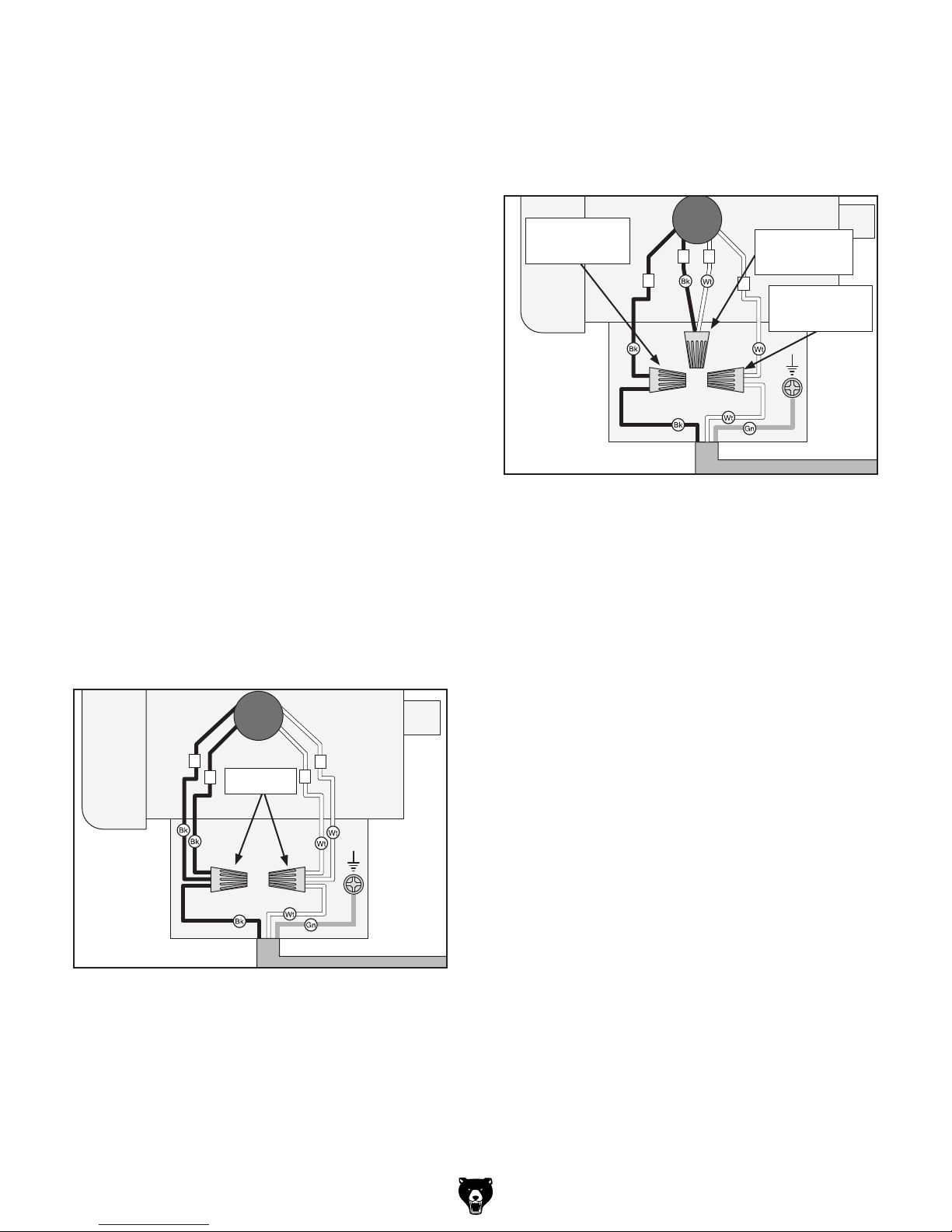
4. Connect the motor wires, as shown in Figure
5, with wire nuts. Once snug, wrap electrical
tape around each wire nut and the connected
wires to reduce the likelihood of the wire nut
vibrating loose during motor operation.
Reconnect
and Tighten
32
4
Connect
and Tighten
1
Reconnect
and Tighten
Items Needed Qty
• Phillips Head Screwdriver #2 ..................... 1
• Electrical Tap e ............................ As Needed
• Wire Nut (14 AWG x 3) ............................... 1
• Plug 6-15 .................................................... 1
To convert the Model G0452Z to 240V:
1. DISCONNECT JOINTER FROM POWER!
2. Cut off the included plug.
3. Open the motor junction box, then remove
the wire nuts indicated in Figure 4.
2
4
Remove
1
3
Ground
Figure 4. Location of wire nuts to be removed.
Ground
Figure 5. Motor wires repositioned for 240V.
5. Close and secure the motor junction box.
6. Install a 6-15 plug on the end of the cord,
according to the instructions and wiring diagrams provided by the plug manufacturer.
—If the plug manufacturer did not include
instructions, the wiring of a generic NEMA
6-15 plug is illustrated on Page 52 .
Model G0452/P/Z (Mfg. Since 08/12)
-13-

SECTION 3: SETUP
Your machine was carefully packaged for safe
transportation. Remove the packaging materials
from around your machine and inspect it. If you
discover any damage, please call us immediately
at (570) 546-9663
Save the containers and all packing materials for
possible inspection by the carrier or its agent.
Otherwise, filing a freight claim can be difficult.
When you are completely satisfied with the condition of your shipment, inventory the contents.
Keep children and pets away
from plastic bags or packing
materials shipped with this
Unpacking
for advice.
SUFFOCATION HAZARD!
Needed for Setup
The following are needed to complete the setup
process, but are not included with your machine.
Description Qty
• Straightedge 4' (or longer) .......................... 1
• Safety Glasses (for each person) ............... 1
• Dust Collection System (optional) .............. 1
• 4" Dust Hose (optional) .............................. 1
• 4" Hose Clamp (optional) ........................... 1
• Phillips Head Screwdriver........................... 1
• Wrench 13mm ............................................ 1
• Wrench 17mm ............................................ 1
• Wrench 19mm ............................................ 1
• Socket Wrench 17mm ................................ 1
• Level ........................................................... 1
machine. Discard immediately.
-14-
Model G0452/P/Z (Mfg. Since 08/12)
Inventory
The following is a list of items shipped with your
machine. Before beginning setup, lay these items
out and inventory them.
If any non-proprietary parts are missing (e.g. a
nut or a washer), we will gladly replace them; or
for the sake of expediency, replacements can be
obtained at your local hardware store.
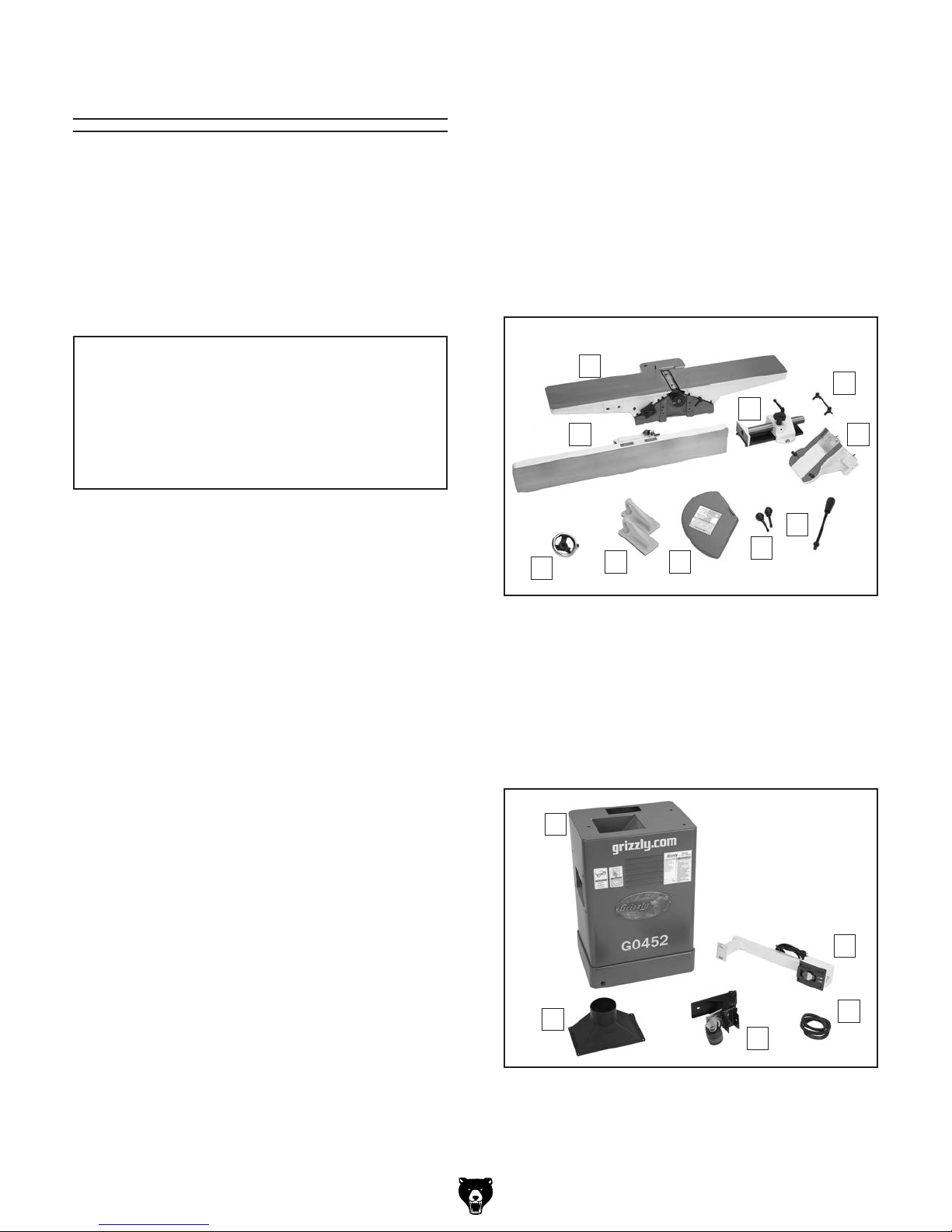
Box 1 (Figure 6): Qty
A. Table Assembly .......................................... 1
B. Fence Carriage Assembly .......................... 1
C. Cutterhead Jig ............................................ 1
D. Carriage Mounting Bracket ......................... 1
E. Infeed Table Lever ...................................... 1
F. Fence Tilt Handles ..................................... 2
G. Cutterhead Guard ....................................... 1
H. Push Blocks ................................................ 2
I. Outfeed Table Handwheel .......................... 1
J. Fence Assembly ......................................... 1
NOTICE
If you cannot find an item on this list, carefully check around/inside the machine and
packaging materials. Often, these items get
lost in packaging materials while unpacking or they are pre-installed at the factory.
Hardware and Tools (Not shown) Qty
• Wrenches 8/10mm & 12/14mm ......... 1 each
• Hex Wrenches 2.5, 3, 4, 6, & 8mm ... 1 each
• Cap Screws M10-1.5 x 20 .......................... 3
• Cap Screws M10-1.5 x 25 .......................... 2
• Hex Bolts M10-1.5 x 55 .............................. 2
• Lock Washers 10mm .................................. 3
• Flat Washers 10mm ................................... 5
• Hex Nuts M10-1.5 ....................................... 2
• Hex Bolt M8-1.25 x 50 ................................ 1
• Cap Screws M8-1.25 x 60 .......................... 4
• Cap Screws M8-1.25 x 25 .......................... 4
• Cap Screws M8-1.25 x 20 .......................... 2
• Lock Washers 8mm.................................... 8
• Flat Washers 8mm ....................................11
• Phillip Head Screws M5-.8 x 15 ................. 4
• Flat Washers 5mm ..................................... 4
A
C
B
J
E
I
Box 2 (Figure 7):
K. Cabinet ....................................................... 1
L. Power Switch and Support Arm ................. 1
M. V-Belt .......................................................... 1
N. Locking Foot Pedal Assembly .................... 1
O. Dust Port ..................................................... 1
K
H
Figure 6. Box 1 inventory.
G
F
D
Model G0452/P/Z (Mfg. Since 08/12)
O
Figure 7. Box 2 inventory.
L
M
N
-15-
The unpainted surfaces of your machine are
coated with a heavy-duty rust preventative that
prevents corrosion during shipment and storage.
This rust preventative works extremely well, but it
will take a little time to clean.
Be patient and do a thorough job cleaning your
machine. The time you spend doing this now will
give you a better appreciation for the proper care
of your machine's unpainted surfaces.
There are many ways to remove this rust preventative, but the following steps work well in a wide
variety of situations. Always follow the manufacturer’s instructions with any cleaning product you
use and make sure you work in a well-ventilated
area to minimize exposure to toxic fumes.
Before cleaning, gather the following:
• Disposable rags
• Cleaner/degreaser (WD•40 works well)
• Safety glasses & disposable gloves
• Plastic paint scraper (optional)
Basic steps for removing rust preventative:
1.
2.
3.
4.
Many cleaning solvents
work in a well-ventilated
Avoid chlorine-based solvents, such as
Cleanup
Gasoline and petroleum
products have low flash
points and can explode
or cause fire if used to
clean machinery. Avo id
using these products
to clean machinery.
Put on safety glasses.
Coat the rust preventative with a liberal
amount of cleaner/degreaser, then let it soak
for 5–10 minutes.
Wipe off the surfaces. If your cleaner/degreas-
er is effective, the rust preventative will wipe
off easily. If you have a plastic paint scraper,
scrape off as much as you can first, then wipe
off the rest with the rag.
are toxic if inhaled. Only
area.
NOTICE
acetone or brake parts cleaner, that may
damage painted surfaces.
T23692—Orange Power Degreaser
A great product for removing the waxy shipping
grease from your machine during clean up.
Figure 4. T23692 Orange Power Degreaser.
271⁄2 "
Repeat Steps 2–3 as necessary until clean,
then coat all unpainted surfaces with a quality
metal protectant to prevent rust.
-16 -
Model G0452/P/Z (Mfg. Since 08/12)
Site Considerations
Place this machine near an existing power source.
Shadows, glare, or strobe effects that may distract
Weight Load
Refer to the Machine Data Sheet for the weight
of your machine. Make sure that the surface upon
which the machine is placed will bear the weight
of the machine, additional equipment that may be
installed on the machine, and the heaviest workpiece that will be used. Additionally, consider the
weight of the operator and any dynamic loading
that may occur when operating the machine.
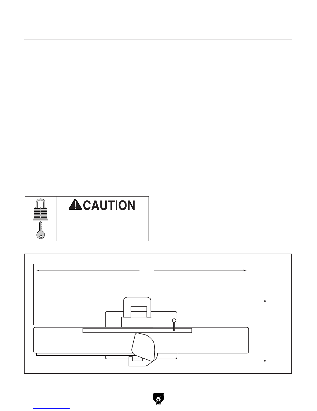
Space Allocation
Consider the largest size of workpiece that will
be processed through this machine and provide
enough space around the machine for adequate
operator material handling or the installation of
auxiliary equipment. With permanent installations,
leave enough space around the machine to open
or remove doors/covers as required by the maintenance and service described in this manual.
See below for required space allocation.
Physical Environment
The physical environment where the machine is
operated is important for safe operation and longevity of machine components. For best results,
operate this machine in a dry environment that is
free from excessive moisture, hazardous chemicals, airborne abrasives, or extreme conditions.
Extreme conditions for this type of machinery are
generally those where the ambient temperature
range exceeds 41°–104°F; the relative humidity
range exceeds 20–95% (non-condensing); or the
environment is subject to vibration, shocks, or
bumps.
Electrical Installation
Make sure all power cords are protected from
traffic, material handling, moisture, chemicals,
or other hazards. Make sure to leave access to
a means of disconnecting the power source or
engaging a lockout/tagout device, if required.
Children or untrained people
may be seriously injured by
this machine. Only install in an
access restricted location.
Lighting
Lighting around the machine must be adequate
enough that operations can be performed safely.
or impede the operator must be eliminated.
46"
27½"
Model G0452/P/Z (Mfg. Since 08/12)
Figure 9. Minimum working clearances.
-17-

Locking Foot Pedal
3. Use a 13mm wrench to install the M8-1.25
x 50mm hex bolt and washer as shown in
Figure 11.
Components and Hardware Needed: Qty
Cabinet .............................................................. 1
Locking Foot Pedal Assembly ........................... 1
Hex Bolts M10-1.5 x 55 ..................................... 2
Flat Washers 10mm .......................................... 2
Hex Nuts M10-1.5 .............................................. 2
Hex Bolt M8-1.25 x 50 ....................................... 1
Flat Washer 8mm .............................................. 1
Tools Needed: Qty
Wrench 17mm .................................................. 1
Socket Wrench 17mm ....................................... 1
Wrench 13mm ................................................... 1
Level .................................................................. 1
To install the locking foot pedal:
1. Lay the cabinet on its side as shown in
Figure 10.
Note: The hex bolt installs from inside.
Figure 11. Installing locking foot pedal.
4. Install the M10-1.5 x 55 hex bolts, flat wash-
ers, and hex nuts through the front of the
locking foot pedal assembly as shown in
Figure 12.
Figure 10. Cabinet.
2. Place the locking foot pedal assembly onto
the cross brace.
Leveling
Feet
Figure 12. Installing locking foot pedal.
5. Raise the cabinet upright.
6. Lock the foot pedal down.
7. Level the cabinet front-to-back and side-
to -side by adjusting the leveling feet (see
Figure 12).
-18-
Model G0452/P/Z (Mfg. Since 08/12)
 Loading...