

Grizzly Extreme Series, G0555X Owner's Manual

MODEL G0555X
14" EXTREME SERIES BANDSAW
OWNER'S MANUAL
(For models manufactured since 9/17)
COPYRIGHT © OCTOBER, 2006 BY GRIZZLY INDUSTRIAL, INC., REVISED AUGUST, 2018 (MN)
WARNING: NO PORTION OF THIS MANUAL MAY BE REPRODUCED IN ANY SHAPE
OR FORM WITHOUT THE WRITTEN APPROVAL OF GRIZZLY INDUSTRIAL, INC.
#TR8670 PRINTED IN TAIWAN
V4.08.18

This manual provides critical safety instructions on the proper setup,
operation, maintenance, and service of this machine/tool. Save this
document, refer to it often, and use it to instruct other operators.
Failure to read, understand and follow the instructions in this manual
may result in fire or serious personal injury—including amputation,
electrocution, or death.
The owner of this machine/tool is solely responsible for its safe use.
This responsibility includes but is not limited to proper installation in
a safe environment, personnel training and usage authorization,
proper inspection and maintenance, manual availability and comprehension, application of safety devices, cutting/sanding/grinding tool
integrity, and the usage of personal protective equipment.
The manufacturer will not be held liable for injury or property damage
from negligence, improper training, machine modifications or misuse.
Some dust created by power sanding, sawing, grinding, drilling, and
other construction activities contains chemicals known to the State
of California to cause cancer, birth defects or other reproductive
harm. Some examples of these chemicals are:
• Lead from lead-based paints.
• Crystalline silica from bricks, cement and other masonry products.
• Arsenic and chromium from chemically-treated lumber.
Your risk from these exposures varies, depending on how often you
do this type of work. To reduce your exposure to these chemicals:
Work in a well ventilated area, and work with approved safety equipment, such as those dust masks that are specially designed to filter
out microscopic particles.

Table of Contents
INTRODUCTION ............................................... 2
Contact Info.................................................... 2
Manual Accuracy ........................................... 2
Machine Data Sheet ...................................... 3
Identification ................................................... 5
SECTION 1: SAFETY ....................................... 6
Safety Instructions for Machinery .................. 6
Additional Safety for Bandsaws ..................... 8
SECTION 2: POWER SUPPLY ........................ 9
SECTION 3: SETUP ....................................... 12
Needed for Setup ......................................... 12
Unpacking .................................................... 12
Inventory ...................................................... 13
Hardware Recognition Chart ....................... 14
Cleanup ........................................................ 15
Site Considerations ...................................... 16
Assembly ..................................................... 17
Dust Collection ............................................. 20
Adjustment Overview ................................... 20
Initial Blade Tracking ................................... 20
Test Run ...................................................... 22
Tensioning Blade ......................................... 23
Adjusting Blade Support Bearings ............... 24
Adjusting Blade Guide Bearings .................. 25
Adjusting Positive Stop ................................ 26
Setting Table Tilt Scale to 0˚ ....................... 27
Leveling Extension Table ............................. 27
Aligning Table .............................................. 28
Aligning Fence ............................................. 28
SECTION 5: ACCESSORIES ......................... 40
SECTION 6: MAINTENANCE ......................... 42
Schedule ...................................................... 42
Cleaning ....................................................... 42
Lubricating ................................................... 42
Redressing Rubber Tires ............................. 42
SECTION 7: SERVICE ................................... 43
Troubleshooting ........................................... 43
Tensioning V-Belt......................................... 46
Replacing V-Belt .......................................... 47
Shimming Table ........................................... 48
Correcting Blade Lead ................................. 48
Calibrating Fence Scale ............................... 49
Wheel Alignment .......................................... 50
Blade Tensioner ........................................... 52
SECTION 8: WIRING ...................................... 53
Wiring Safety Instructions ............................ 53
110V Wiring Diagram ................................... 54
220V Wiring Diagram ................................... 55
SECTION 9: PARTS ....................................... 56
Main ............................................................. 56
Table, Fence & Guides ................................ 59
Stand ............................................................ 61
Labels & Cosmetics ..................................... 62
WARRANTY AND RETURNS ........................ 65
SECTION 4: OPERATIONS ........................... 29
Operation Overview ..................................... 29
General Overview ........................................ 30
Disabling & Locking Switch.......................... 30
Workpiece Inspection................................... 31
Setting Upper Blade Guide Height .............. 31
Adjusting Table Tilt ...................................... 32
Blade Selection ............................................ 32
Blade Care & Break-In ................................. 35
Blade Breakage ........................................... 35
Changing Blade ........................................... 36
Scale Calibration .......................................... 37
Ripping ......................................................... 37
Crosscutting ................................................. 38
Resawing ..................................................... 38
Cutting Curves ............................................. 39
Stacked Cuts................................................ 39

INTRODUCTION
We stand behind our machines! If you have questions or need help, contact us with the information
below. Before contacting, make sure you get the
serial number
from the
machine ID label. This will help us help you faster.
We want your feedback on this manual. What did
you like about it? Where could it be improved?
Please take a few minutes to give us feedback.
Email: manuals@grizzly.com
We are proud to provide a high-quality owner’s
manual with your new machine!
We
instructions, specifications, drawings, and photographs
in this manual. Sometimes we make mistakes, but
our policy of continuous improvement also means
that
you receive is
slightly different than shown in the manual
If you find this to be the case, and the difference
between the manual and machine leaves you
confused or unsure about something
check our
website for an updated version. W
current
manuals and
on our web-
site at
Alternatively, you can call our Technical Support
for help. Before calling, make sure you write down
the
from
the machine ID label (see below). This information
is required for us to provide proper tech support,
and it helps us determine if updated documentation is available for your machine.
Contact Info
and manufacture date
Grizzly Technical Support
1815 W. Battlefield
Springfield, MO 65807
Phone: (570) 546-9663
Email: techsupport@grizzly.com
Grizzly Documentation Manager
P.O. Box 2069
Bellingham, WA 98227-2069
Manual Accuracy
made every effort to be exact with the
sometimes the machine
.
,
e post
manual updates for free
www.grizzly.com.
Manufacture Date and Serial Number
Manufacture Date
Serial Number
-2-
G0555X (Mfd. Since 9/17)

Machine Data Sheet
MACHINE DATA
SHEET
Customer Service #: (570) 546-9663 · To Order Call: (800) 523-4777 · Fax #: (800) 438-5901
MODEL G0555X 14" EXTREME SERIES BANDSAW
Product Dimensions:
Weight.............................................................................................................................................................. 236 lbs.
Width (side-to-side) x Depth (front-to-back) x Height..................................................................... 30 x 26 x 67-1/4 in.
Footprint (Length x Width)..................................................................................................................... 17-1/4 x 16 in.
Shipping Dimensions:
Carton #1
Type........................................................................................................................................... Cardboard Box
Content................................................................................................................................................. Machine
Weight................................................................................................................................................... 199 Lbs.
Length x Width x Height............................................................................................................. 21 x 41 x 20 in.
Must Ship Upright.......................................................................................................................................... No
Carton #2
Type........................................................................................................................................... Cardboard Box
Content...................................................................................................................................................... Stand
Weight..................................................................................................................................................... 60 Lbs.
Length x Width x Height............................................................................................................. 17 x 18 x 26 in.
Must Ship Upright.......................................................................................................................................... No
Electrical:
Power Requirement............................................................................................. 110V or 220V, Single-Phase, 60 Hz
Prewired Voltage.................................................................................................................................................. 110V
Full-Load Current Rating.................................................................................................... 15A at 110V, 7.5A at 220V
Minimum Circuit Size.......................................................................................................... 20A at 110V, 15A at 220V
Connection Type....................................................................................................................................... Cord & Plug
Power Cord Included.............................................................................................................................................. Yes
Power Cord Length................................................................................................................................................. 6 ft.
Power Cord Gauge......................................................................................................................................... 14 AWG
Plug Included.......................................................................................................................................................... Yes
Included Plug Type................................................................................................................................. 5-15 for 110V
Recommended Plug Type...................................................................................................................... 6-15 for 220V
Switch Type.................................................................................................................... ON/OFF Push Button Switch
Motors:
Main
Horsepower............................................................................................................................................. 1.5 HP
Phase............................................................................................................................................ Single-Phase
Amps.................................................................................................................................................... 15A/7.5A
Speed................................................................................................................................................ 1725 RPM
Type................................................................................................................. TEFC Capacitor-Start Induction
Power Transfer .................................................................................................................................. Belt Drive
Bearings..................................................................................................... Shielded & Permanently Lubricated
Centrifugal Switch/Contacts Type......................................................................................................... External
G0555X (Mfd. Since 9/17)
-3-

Main Specifications:
Main Specifications
Bandsaw Size............................................................................................................................................ 14 in.
Max Cutting Width (Left of Blade)........................................................................................................ 13-1/2 in.
Max Cutting Width (Left of Blade) w/Fence......................................................................................... 12-1/4 in.
Max Cutting Height (Resaw Height)............................................................................................................ 6 in.
Blade Speeds..................................................................................................................................... 3000 FPM
Blade Information
Standard Blade Length........................................................................................................................ 93-1/2 in.
Blade Length Range.............................................................................................................. 92-1/2 – 93-1/2 in.
Blade Width Range.......................................................................................................................... 1/8 – 3/4 in.
Type of Blade Guides...................................................................................................................... Ball Bearing
Guide Post Adjustment Type.................................................................................................................. Manual
Has Quick-Release...................................................................................................................................... Yes
Table Information
Table Length.............................................................................................................................................. 14 in.
Table Width......................................................................................................................................... 20-1/2 in.
Table Thickness.................................................................................................................................... 1-1/2 in.
Table Tilt.......................................................................................................................... Left 15, Right 45 deg.
Table Tilt Adjustment Type..................................................................................................................... Manual
Floor-to-Table Height................................................................................................................................. 44 in.
Fence Locking Position.............................................................................................................................. Front
Fence is Adjustable for Blade Lead.............................................................................................................. Yes
Resaw Fence Attachment Included.............................................................................................................. Yes
Miter Gauge Included................................................................................................................................... Yes
Construction Materials
Table....................................................................................................................... Precision Ground Cast Iron
Trunnion............................................................................................................................................. Aluminum
Fence............................................................................................................ Extruded Aluminum and Cast Iron
Base/Stand............................................................................................................................. Pre-Formed Steel
Frame/Body......................................................................................................................................... Cast Iron
Wheels................................................................................................................ Computer-Balanced Cast Iron
Tire.......................................................................................................................................................... Rubber
Wheel Cover ......................................................................................................................... Pre-Formed Steel
Paint Type/Finish...................................................................................................................... Powder Coating
Other Related Information
Wheel Diameter................................................................................................................................... 13-3/4 in.
Wheel Width........................................................................................................................................ 1-3/16 in.
Number of Dust Ports....................................................................................................................................... 1
Dust Port Size.............................................................................................................................................. 4 in.
Compatible Mobile Base........................................................................................................................ D2260A
Other Specifications:
Country of Origin .............................................................................................................................................. Taiwan
Warranty ........................................................................................................................................................... 1 Year
Approximate Assembly & Setup Time ...................................................................................................... 1-1/2 Hours
Serial Number Location ........................................................................................................... ID Label on Top Cover
ISO 9001 Factory .................................................................................................................................................. Yes
Certified by a Nationally Recognized Testing Laboratory (NRTL) ......................................................................... Yes
Awards .................................................................................................... Popular Woodworking Best New Tool 2003
-4-
G0555X (Mfd. Since 9/17)
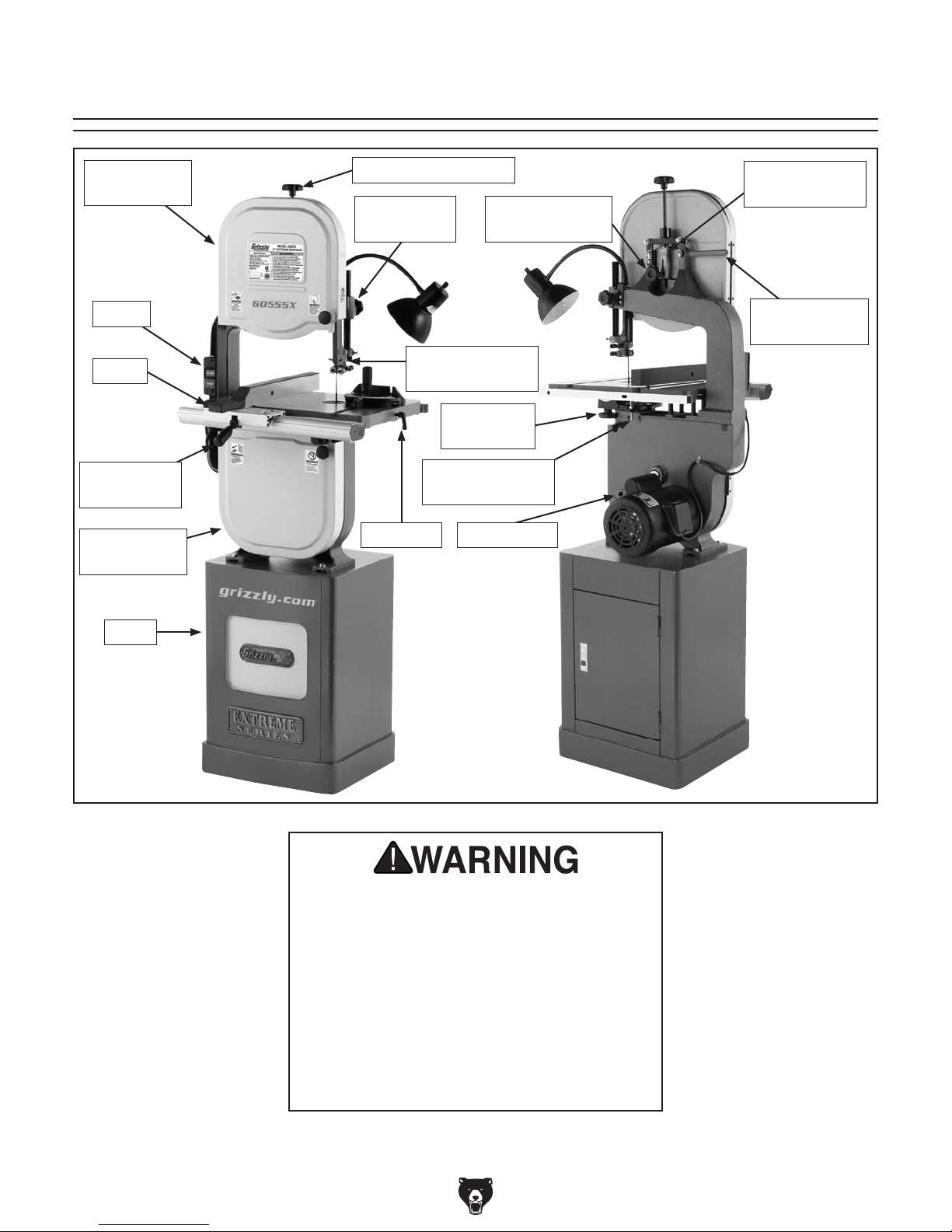
Identification
Upper Wheel
Guard
Switch
Fence
Fence Lock
Handle
Lower Wheel
Guard
Blade Tension Knob
Guide Post
Lock Knob
Upper Blade
Guide Assembly
Lower Blade
Guide Assembly
Blade Tracking
Table Tilt
Lock Knob
4" Dust PortTable Pin
Blade Tension
Scale
Knob
Blade Quick
Release Lever
Stand
For Your Own Safety, Read Instruction
Manual Before Operating Bandsaw
a) Wear eye protection.
b) Do not remove jammed cutoff pieces
until blade has stopped.
c) Maintain proper adjustment of blade
tension, blade guides, and thrust
bearings.
d) Adjust upper guide to just clear
workpiece.
e) Hold workpiece firmly against table.
G0555X (Mfd. Since 9/17)
-5-
SECTION 1: SAFETY
For Your Own Safety, Read Instruction
Manual Before Operating This Machine
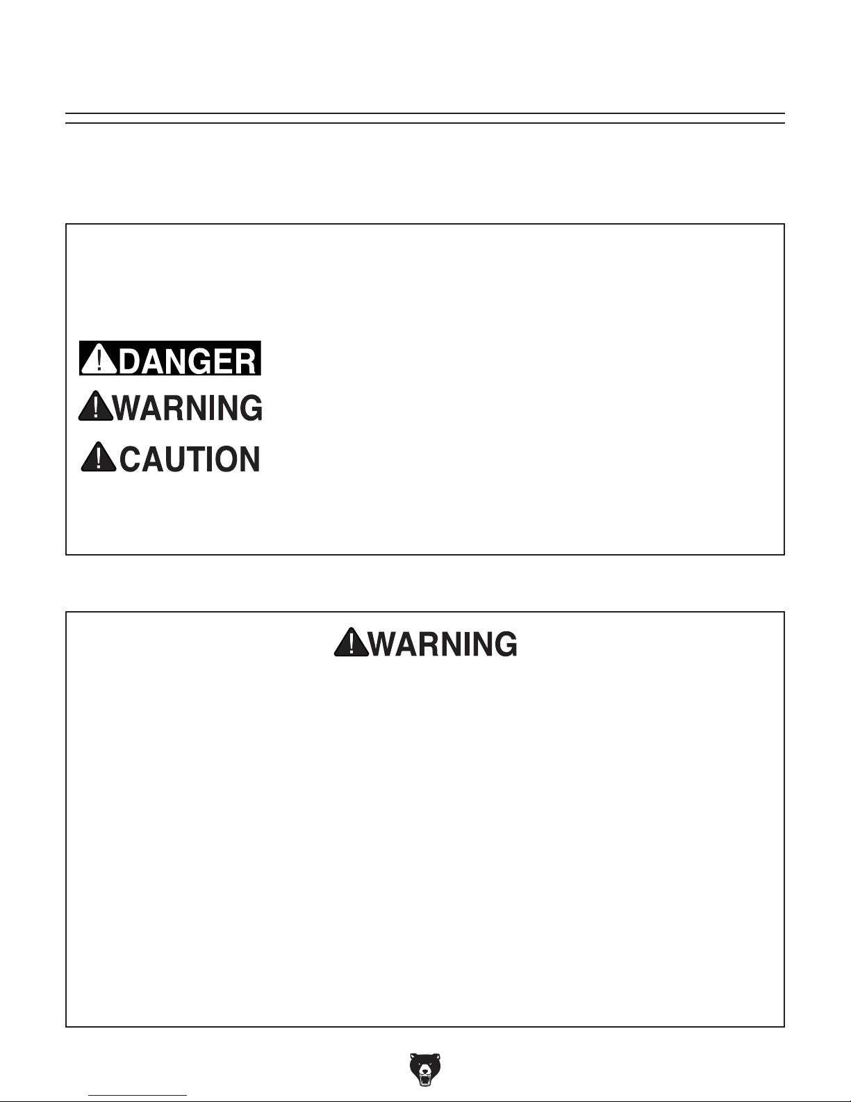
The purpose of safety symbols is to attract your attention to possible hazardous conditions.
This manual uses a series of symbols and signal words intended to convey the level of importance of the safety messages. The progression of symbols is described below. Remember that
safety messages by themselves do not eliminate danger and are not a substitute for proper
accident prevention measures. Always use common sense and good judgment.
Indicates an imminently hazardous situation which, if not avoided,
WILL result in death or serious injury.
Indicates a potentially hazardous situation which, if not avoided,
COULD result in death or serious injury.
Indicates a potentially hazardous situation which, if not avoided,
MAY result in minor or moderate injury. It may also be used to alert
against unsafe practices.
This symbol is used to alert the user to useful information about
NOTICE
proper operation of the machine.
Safety Instructions for Machinery
OWNER’S MANUAL. Read and understand this
owner’s manual BEFORE using machine.
TRAINED OPERATORS ONLY. Untrained operators have a higher risk of being hurt or killed.
Only allow trained/supervised people to use this
machine. When machine is not being used, disconnect power, remove switch keys, or lock-out
machine to prevent unauthorized use—especially
around children. Make your workshop kid proof!
DANGEROUS ENVIRONMENTS. Do not use
machinery in areas that are wet, cluttered, or have
poor lighting. Operating machinery in these areas
greatly increases the risk of accidents and injury.
MENTAL ALERTNESS REQUIRED. Full mental
alertness is required for safe operation of machinery. Never operate under the influence of drugs or
alcohol, when tired, or when distracted.
ELECTRICAL EQUIPMENT INJURY RISKS. You
can be shocked, burned, or killed by touching live
electrical components or improperly grounded
machinery. To reduce this risk, only allow qualified
service personnel to do electrical installation or
repair work, and always disconnect power before
accessing or exposing electrical equipment.
DISCONNECT POWER FIRST.
nect machine from power supply BEFORE making
adjustments, changing tooling, or servicing machine.
This prevents an injury risk from unintended startup
or contact with live electrical components.
EYE PROTECTION. Always wear ANSI-approved
safety glasses or a face shield when operating or
observing machinery to reduce the risk of eye
injury or blindness from flying particles. Everyday
eyeglasses are NOT approved safety glasses.
Always discon-
-6-
G0555X (Mfd. Since 9/17)

WEARING PROPER APPAREL. Do not wear
clothing, apparel or jewelry that can become
entangled in moving parts. Always tie back or
cover long hair. Wear non-slip footwear to reduce
risk of slipping and losing control or accidentally
contacting cutting tool or moving parts.
HAZARDOUS DUST. Dust created by machinery
operations may cause cancer, birth defects, or
long-term respiratory damage. Be aware of dust
hazards associated with each workpiece material. Always wear a NIOSH-approved respirator to
reduce your risk.
HEARING PROTECTION. Always wear hearing protection when operating or observing loud
machinery. Extended exposure to this noise
without hearing protection can cause permanent
hearing loss.
REMOVE ADJUSTING TOOLS. Tools left on
machinery can become dangerous projectiles
upon startup. Never leave chuck keys, wrenches,
or any other tools on machine. Always verify
removal before starting!
USE CORRECT TOOL FOR THE JOB. Only use
this tool for its intended purpose—do not force
it or an attachment to do a job for which it was
not designed. Never make unapproved modifications—modifying tool or using it differently than
intended may result in malfunction or mechanical
failure that can lead to personal injury or death!
AWKWARD POSITIONS. Keep proper footing
and balance at all times when operating machine.
Do not overreach! Avoid awkward hand positions
that make workpiece control difficult or increase
the risk of accidental injury.
CHILDREN & BYSTANDERS. Keep children and
bystanders at a safe distance from the work area.
Stop using machine if they become a distraction.
GUARDS & COVERS. Guards and covers reduce
accidental contact with moving parts or flying
debris. Make sure they are properly installed,
undamaged, and working correctly BEFORE
operating machine.
FORCING MACHINERY. Do not force machine.
It will do the job safer and better at the rate for
which it was designed.
NEVER STAND ON MACHINE. Serious injury
may occur if machine is tipped or if the cutting
tool is unintentionally contacted.
STABLE MACHINE. Unexpected movement during operation greatly increases risk of injury or
loss of control. Before starting, verify machine is
stable and mobile base (if used) is locked.
USE RECOMMENDED ACCESSORIES. Consult
this owner’s manual or the manufacturer for recommended accessories. Using improper accessories will increase the risk of serious injury.
UNATTENDED OPERATION. To reduce the
risk of accidental injury, turn machine OFF and
ensure all moving parts completely stop before
walking away. Never leave machine running
while unattended.
MAINTAIN WITH CARE. Follow all maintenance
instructions and lubrication schedules to keep
machine in good working condition. A machine
that is improperly maintained could malfunction,
leading to serious personal injury or death.
DAMAGED PARTS. Regularly inspect machine
for damaged, loose, or mis-adjusted parts—or
any condition that could affect safe operation.
Immediately repair/replace BEFORE operating
machine. For your own safety, DO NOT operate
machine with damaged parts!
MAINTAIN POWER CORDS. When disconnecting cord-connected machines from power, grab
and pull the plug—NOT the cord. Pulling the cord
may damage the wires inside. Do not handle
cord/plug with wet hands. Avoid cord damage by
keeping it away from heated surfaces, high traffic
areas, harsh chemicals, and wet/damp locations.
EXPERIENCING DIFFICULTIES. If at any time
you experience difficulties performing the intended operation, stop using the machine! Contact our
Technical Support at (570) 546-9663.
G0555X (Mfd. Since 9/17)
-7-

Additional Safety for Bandsaws
Serious cuts, amputation, or death can occur from contact with the moving saw blade during
operation or if blade breakage occurs. To reduce this risk, anyone operating this machine
MUST completely heed the hazards and warnings below.
HAND PLACEMENT. Placing hands or fingers
in line with blade during operation may result in
serious injury if hands slip or workpiece moves
unexpectedly. Do not position fingers or hands in
line with blade, and never reach under table while
blade is moving.
SMALL/NARROW WORKPIECES. If hands slip
during a cut while holding small workpieces
with fingers, serious personal injury could occur.
Always support/feed small or narrow workpieces
with push sticks, push blocks, jig, vise, or some
type of clamping fixture.
BLADE SPEED. Cutting workpiece before blade
is at full speed could cause blade to grab workpiece and pull hands into blade. Allow blade to
reach full speed before starting cut. DO NOT start
machine with workpiece contacting blade.
FEED RATE. To avoid risk of workpiece slipping
and causing operator injury, always feed stock
evenly and smoothly.
BLADE CONDITION. Dull blades require more
effort to perform cut, increasing risk of accidents.
Do not operate with dirty, dull, cracked or badly
worn blades. Inspect blades for cracks and missing teeth before each use. Always maintain proper
blade tension and tracking while operating.
CLEARING JAMS AND CUTOFFS. Always stop
bandsaw and disconnect power before clearing
scrap pieces that get stuck between blade and
table insert. Use brush or push stick, not hands,
to clean chips/cutoff scraps from table.
BLADE CONTROL. To avoid risk of injury due to
blade contact, always allow blade to stop on its
own. DO NOT try to stop or slow blade with your
hand or the workpiece.
GUARDS /COVERS. Blade guards and covers
protect operator from the moving bandsaw blade.
The wheel covers protect operator from getting
entangled with rotating wheels or other moving
pa r t s. O N LY operate this bandsaw with blade
guard in proper position and wheel covers completely closed.
BLADE REPLACEMENT. To avoid mishaps that
could result in operator injury, make sure blade
teeth face down toward table and blade is properly tensioned and tracked before operating.
UPPER BLADE GUIDE SUPPORT. To reduce
exposure of operator to blade and provide maximum blade support while cutting, keep upper
blade guides adjusted to just clear workpiece.
CUTTING TECHNIQUES. To avoid blade getting
pulled off wheels or accidentally breaking and
striking operator, always turn bandsaw OFF and
wait for blade to come to a complete stop before
backing workpiece out of blade. DO NOT back
workpiece away from blade while bandsaw is running. DO NOT force or twist blade while cutting,
especially when sawing small curves. This could
result in blade damage or breakage.
WORKPIECE SUPPORT. To maintain maximum
control and reduce risk of blade contact/breakage, always ensure adequate support of long/
large workpieces. Always keep workpiece flat and
firm against table/fence when cutting to avoid loss
of control. If necessary, use a jig or other workholding device.
WORKPIECE MATERIAL. This machine is
intended for cutting natural and man-made wood
products, and laminate covered wood products.
This machine is NOT designed to cut metal,
glass, stone, tile, etc.
-8-
G0555X (Mfd. Since 9/17)

SECTION 2: POWER SUPPLY
Before installing the machine, consider the availability and proximity of the required power supply
circuit. If an existing circuit does not meet the
requirements for this machine, a new circuit must
be installed. To minimize the risk of electrocution,
fire, or equipment damage, installation work and
electrical wiring must be done by an electrician or
qualified service personnel in accordance with all
applicable codes and standards.
or equipment damage
may occur if machine is
not properly grounded
and connected to power
The full-load current rating is the amperage a
machine draws at 100% of the rated output power.
On machines with multiple motors, this is the
amperage drawn by the largest motor or sum of all
motors and electrical devices that might operate
at one time during normal operations.
The full-load current is not the maximum amount
of amps that the machine will draw. If the machine
is overloaded, it will draw additional amps beyond
the full-load rating.
If the machine is overloaded for a sufficient length
of time, damage, overheating, or fire may result—
especially if connected to an undersized circuit.
To reduce the risk of these hazards, avoid overloading the machine during operation and make
sure it is connected to a power supply circuit that
meets the specified circuit requirements.
For your own safety and protection of
A power supply circuit includes all electrical
equipment between the breaker box or fuse panel
in the building and the machine. The power supply circuit used for this machine must be sized to
safely handle the full-load current drawn from the
machine for an extended period of time. (If this
machine is connected to a circuit protected by
fuses, use a time delay fuse marked D.)
Note: Circuit requirements in this manual apply to
a dedicated circuit—where only one machine will
be running on the circuit at a time. If machine will
be connected to a shared circuit where multiple
machines may be running at the same time, consult an electrician or qualified service personnel to
ensure circuit is properly sized for safe operation.
This machine can be converted to operate on a
power supply circuit that has a verified ground
and meets the requirements listed below. (Refer
to Voltage Conversion instructions for details.)
This machine is prewired to operate on a power
supply circuit that has a verified ground and meets
the following requirements:
Availability
Electrocution, fire, shock,
supply.
Full-Load Current Rating
Circuit Information
property, consult an electrician if you are
unsure about wiring practices or electrical
codes in your area.
Full-Load Current Rating at 110V ...... 15 Amps
Full-Load Current Rating at 220V .... 7.5 Amps
G0555X (Mfd. Since 9/17)
Circuit Requirements for 110V
Nominal Voltage .................... 110V, 115V, 120V
Cycle .......................................................... 60 Hz
Phase ........................................... Single-Phase
Power Supply Circuit ......................... 20 Amps
Plug/Receptacle ............................. NEMA 5-15
Circuit Requirements for 220V
Nominal Voltage .........208V, 22 0V, 2 3 0V, 2 4 0V
Cycle .......................................................... 60 Hz
Phase ........................................... Single-Phase
Power Supply Circuit ......................... 15 Amps
Plug/Receptacle ............................. NEMA 6-15
-9-
Improper connection of the equipment-grounding
wire can result in a risk of electric shock. The
wire with green insulation (with or without yellow
stripes) is the equipment-grounding wire. If repair
or replacement of the power cord or plug is necessary, do not connect the equipment-grounding
wire to a live (current carrying) terminal.
Check with a qualified electrician or service personnel if you do not understand these grounding
requirements, or if you are in doubt about whether
the tool is properly grounded. If you ever notice
that a cord or plug is damaged or worn, disconnect it from power, and immediately replace it with
a new one.
Grounding Requirements
This machine MUST be grounded. In the event
of certain malfunctions or breakdowns, grounding
reduces the risk of electric shock by providing a
path of least resistance for electric current.
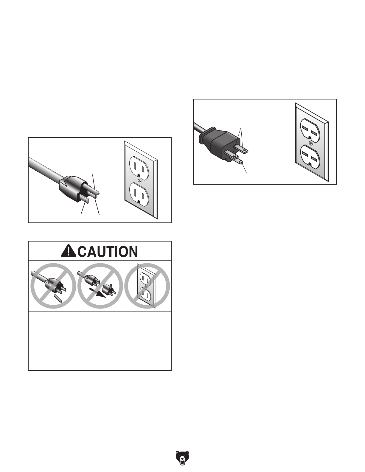
For 110V operation: This machine is equipped
with a power cord that has an equipment-grounding wire and a grounding plug (see following figure). The plug must only be inserted into a matching receptacle (outlet) that is properly installed
and grounded in accordance with all local codes
and ordinances.
For 220V operation: The plug specified under
“
page has a grounding prong that must be attached
to the equipment-grounding wire on the included
power cord. The plug must only be inserted into
a matching receptacle (see following figure) that
is properly installed and grounded in accordance
with all local codes and ordinances.
it will not fit the outlet, have a qualified
electrician install the proper outlet with a
Circuit Requirements for 220V” on the previous
GROUNDED
6-15 RECEPTACLE
Current Carrying Prongs
GROUNDED
5-15 RECEPTACLE
Grounding Prong
5-15 PLUG
Neutral Hot
Figure 1. Typical 5-15 plug and receptacle.
6-15 PLUG
Grounding Prong
Figure 2. Typical 6-15 plug and receptacle.
SHOCK HAZARD!
Two-prong outlets do not meet the grounding
requirements for this machine. Do not modify
or use an adapter on the plug provided—if
verified ground.
-10 -
G0555X (Mfd. Since 9/17)

Extension Cords
We do not recommend using an extension cord
with this machine.
cord, only use it if absolutely necessary and only
on a temporary basis.
Extension cords cause voltage drop, which can
damage electrical components and shorten motor
life. Voltage drop increases as the extension cord
size gets longer and the gauge size gets smaller
(higher gauge numbers indicate smaller sizes).
Any extension cord used with this machine must
be in good condition and contain a ground wire
and matching plug/receptacle. Additionally, it must
meet the following size requirements:
If you must use an extension
Minimum Gauge Size ...........................14 AWG
Maximum Length (Shorter is Better).......50 ft.
Work Lamp
The work lamp included with this machine is not
part of the electrical wiring of the machine. The
lamp must be connected to a separate grounded
120V circuit that accepts the included 5-15 plug.
Voltage Conversion
The voltage conversion MUST be performed by
an electrician or qualified service personnel.
To perform the voltage conversion, install the
correct plug and rewire the motor to the new voltage, according to the provided wiring diagram on
Page 55.
The START/STOP switch is a dual-voltage switch
(110V/220V) and does not need to be re-wired or
replaced.
Note: If the diagram included on the motor conflicts with the one in this manual, the motor may
have changed since the manual was printed. Use
the diagram provided inside the motor wiring junction box.
To convert machine to 220V:
1. DISCONNECT MACHINE FROM POWER!
2. Replace the 5-15 plug on the power cord with
a 6-15 plug.
Use only a replacement light bulb that is rated
40 watts or below. When changing the light bulb,
always disconnect the lamp from power and wait
for the bulb to cool.
The work lamp is only
designed to safely operate
with 120V power. Always
disconnect the work lamp
from power and wait for the
light bulb to cool before
replacing the bulb.
3. Re-wire the motor as illustrated in the wiring
diagram on Page 55.
To reduce the risk of electrocution, fire, or
equipment damage, installation work and
electrical wiring must be done by an electrician or qualified service personnel in accordance with all applicable codes and standards, including the National Electric Code
(NEC) and the Occupational Safety and
Health Administration (OSHA) regulations.
G0555X (Mfd. Since 9/17)
-11-
SECTION 3: SETUP
This machine was carefully packaged for safe
transport. When unpacking, separate all enclosed
items from packaging materials and inspect them
for shipping damage.
,
please
IMPORTANT:
you are completely satisfied with the machine and
have resolved any issues between Grizzly or the
shipping agent. You MUST have the original pack-
aging to file a freight claim. It is also extremely
helpful if you need to return your machine later.
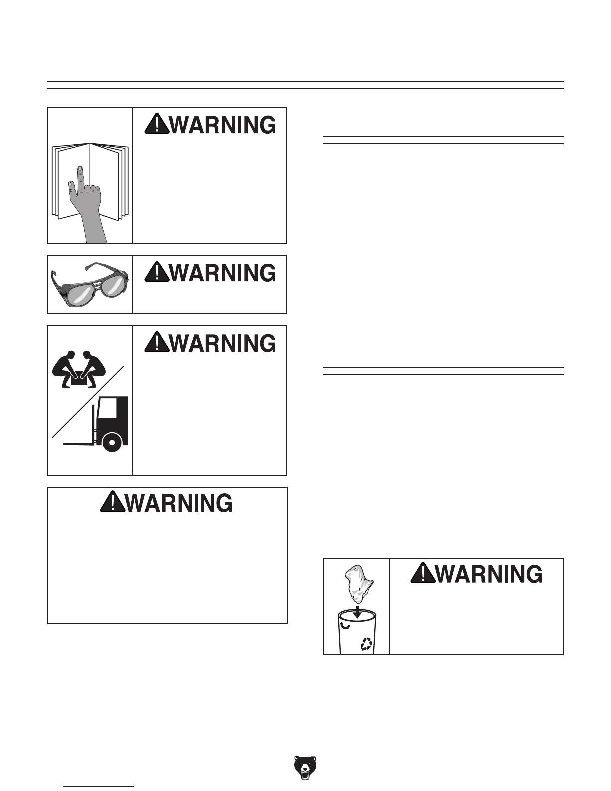
Keep children and pets away
from plastic bags or packing
materials shipped with this
The following items are needed, but not included,
for the setup/assembly of this machine.
Needed for Setup
This machine presents
serious injury hazards
to untrained users. Read
through this entire manual to become familiar with
the controls and operations before starting the
machine!
Wear safety glasses during
the entire setup process!
Description Qty
• Straightedge ............................................... 1
• Level ........................................................... 1
• Another Person for Lifting Help .................. 1
• Square ........................................................ 1
• Safety Glasses (for each person) .............. 1
• Dust Collection System .............................. 1
• 4" Dust Hose (length as needed) ............... 1
• 4" Hose Clamp ........................................... 1
HEAVY LIFT!
Straining or crushing injury
may occur from improperly
lifting machine or some of
its parts. To reduce this risk,
get help from other people
and use a forklift (or other
lifting equipment) rated for
weight of this machine.
Like all machinery there is potential danger
when operating this machine. Accidents are
frequently caused by lack of familiarity or
failure to pay attention. Use this machine
with respect and caution to lessen the possibility of operator injury. If normal safety
precautions are overlooked or ignored, serious personal injury may occur.
Unpacking
If items are damaged
call us immediately at (570) 546-9663.
Save all packaging materials until
SUFFOCATION HAZARD!
machine. Discard immediately.
-12-
G0555X (Mfd. Since 9/17)
The following is a list of items shipped with your
machine. Before beginning setup, lay these items
out and inventory them.
If any non-proprietary parts are missing (e.g. a
nut or a washer), we will gladly replace them; or
for the sake of expediency, replacements can be
obtained at your local hardware store.
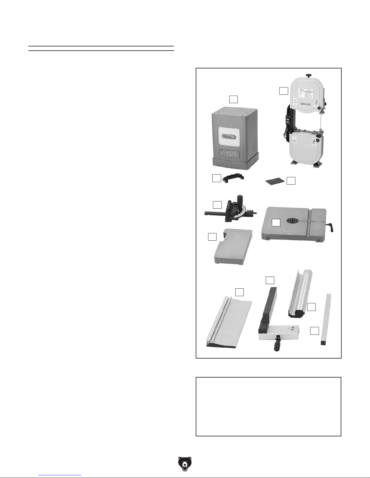
Inventory
Main Components (Figure 3) Qty
A. Stand .......................................................... 1
B. Bandsaw Unit ............................................. 1
C. Trunnion Base ............................................ 1
D. Lever Board ................................................ 1
E. Miter Gauge ................................................ 1
F. Extension Table .......................................... 1
G. Main Table .................................................. 1
H. Fence Assembly ......................................... 1
I. Resaw Fence ............................................. 1
J. Front Fence Rail ......................................... 1
K. Rear Fence Rail ......................................... 1
• Moving Plate (Resaw) ................................ 1
• Lock Handle M8-1.25 x 44 (Resaw) ........... 1
• Flat Washer 8mm (Resaw) ........................ 1
• Hex Wrenches 3, 4, 5mm ................. 1 Each
B
A
C
E
D
G
Fasteners and Tools (not shown) Qty
• Rubber Feet (Stand) .................................. 4
• Hex Nuts
• Flat Washers 10mm (Feet/Stand) .............. 8
• Hex Bolts M8-1.25 x 35 (Bandsaw/Stand) . 4
• Flat Washers 8mm (Bandsaw/Stand) ........ 8
• Lock Washers 8mm (Bandsaw/Stand) ....... 4
• Hex Nuts M8-1.25 (Bandsaw/Stand) .......... 4
• Hex Bolts M8-1.25 x 30 (Trunnion Base) ... 2
• Lock Washers 8mm (Trunnion Base)......... 2
• Hex Bolt M8-1.25 x 80 (Positive Stop) ....... 1
• Hex Nut M8-1.25 (Positive Stop) ............... 1
• Spacers (Lever Board) ............................... 4
• Cap Screws M8-1.25 x 60 (Lever Board) .. 4
• Hex Nuts M8-1.25 (Lever Board) ............... 4
• Set Screws M8-1.25 x 20 (Lever Board) .... 4
• Cap Screws M6-1 x 25 (Lever Board) ....... 4
• Lock Washers 6mm (Lever Board) ............ 4
• Flat Washers 6mm (Lever Board) .............. 4
• Knobs M10-1.5 (Table) .............................. 2
• Hex Bolts M6-1 x 20 (Front Rail) ............... 2
• Flat Washers 6mm (Front Rail) .................. 2
• Lock Washers 6mm (Front Rail) ................ 2
• Cap Screws M6-1 x 16 (Rear Rails) .......... 2
• Lock Handle M8-1.25 x 20 (Fence) ............ 1
• Hex Nut M8-1.25 (Fence) ........................... 1
3
⁄8-16 (Feet/Stand) ...................... 8
F
H
I
J
K
Figure 3. Main components inventory.
NOTICE
If you cannot find an item on this list, carefully check around/inside the machine and
packaging materials. Often, these items get
lost in packaging materials while unpacking or they are pre-installed at the factory.
G0555X (Mfd. Since 9/17)
-13-

Hardware Recognition Chart
USE THIS CHART TO MATCH UP
HARDWARE DURING THE INVENTORY
AND ASSEMBLY PROCESS.
Flat
Head
Cap
Screw
5mm
-14-
5mm
G0555X (Mfd. Since 9/17)
The unpainted surfaces of your machine are
coated with a heavy-duty rust preventative that
prevents corrosion during shipment and storage.
This rust preventative works extremely well, but it
will take a little time to clean.
Be patient and do a thorough job cleaning your
machine. The time you spend doing this now will
give you a better appreciation for the proper care
of your machine's unpainted surfaces.
There are many ways to remove this rust preventative, but the following steps work well in a wide
variety of situations. Always follow the manufacturer’s instructions with any cleaning product you
use and make sure you work in a well-ventilated
area to minimize exposure to toxic fumes.
Before cleaning, gather the following:
• Disposable rags
• Cleaner/degreaser (WD•40 works well)
• Safety glasses & disposable gloves
• Plastic paint scraper (optional)
Basic steps for removing rust preventative:
1.
2.
3.
4.
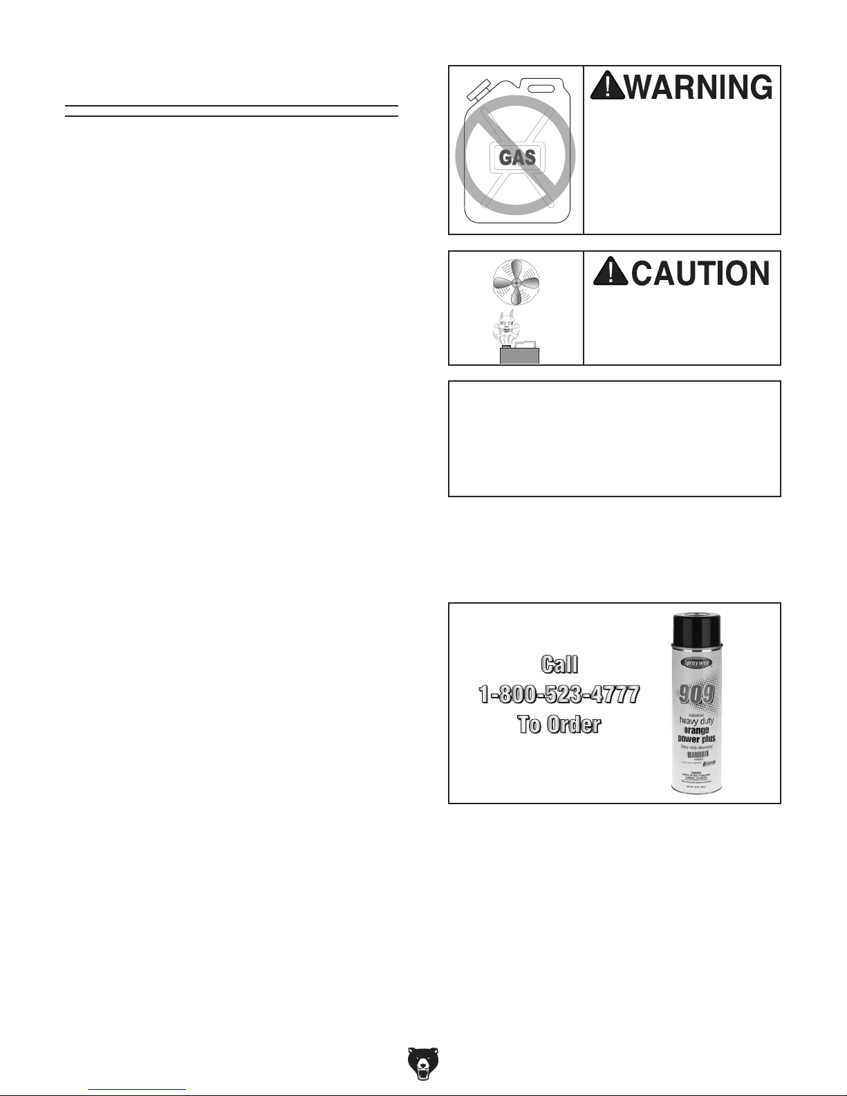
Many cleaning solvents
work in a well-ventilated
Cleanup
Gasoline and petroleum
products have low flash
points and can explode
or cause fire if used to
clean machinery. Av oi d
using these products
to clean machinery.
Put on safety glasses.
Coat the rust preventative with a liberal
amount of cleaner/degreaser, then let it soak
for 5–10 minutes.
Wipe off the surfaces. If your cleaner/degreas-
er is effective, the rust preventative will wipe
off easily. If you have a plastic paint scraper,
scrape off as much as you can first, then wipe
off the rest with the rag.
are toxic if inhaled. Only
area.
NOTICE
Avoid harsh solvents like acetone or brake
parts cleaner that may damage painted surfaces. Always test on a small, inconspicuous location first.
T23692—Orange Power Degreaser
A great product for removing the waxy shipping grease from the non-painted parts of the
machine during clean up.
Repeat Steps 2–3 as necessary until clean,
then coat all unpainted surfaces with a quality
metal protectant to prevent rust.
G0555X (Mfd. Since 9/17)
Figure 4. T23692 Orange Power Degreaser.
-15-
Site Considerations
Weight Load
Refer to the
of your machine. Make sure that the surface upon
which the machine is placed will bear the weight
of the machine, additional equipment that may be
installed on the machine, and the heaviest workpiece that will be used. Additionally, consider the
weight of the operator and any dynamic loading
that may occur when operating the machine.
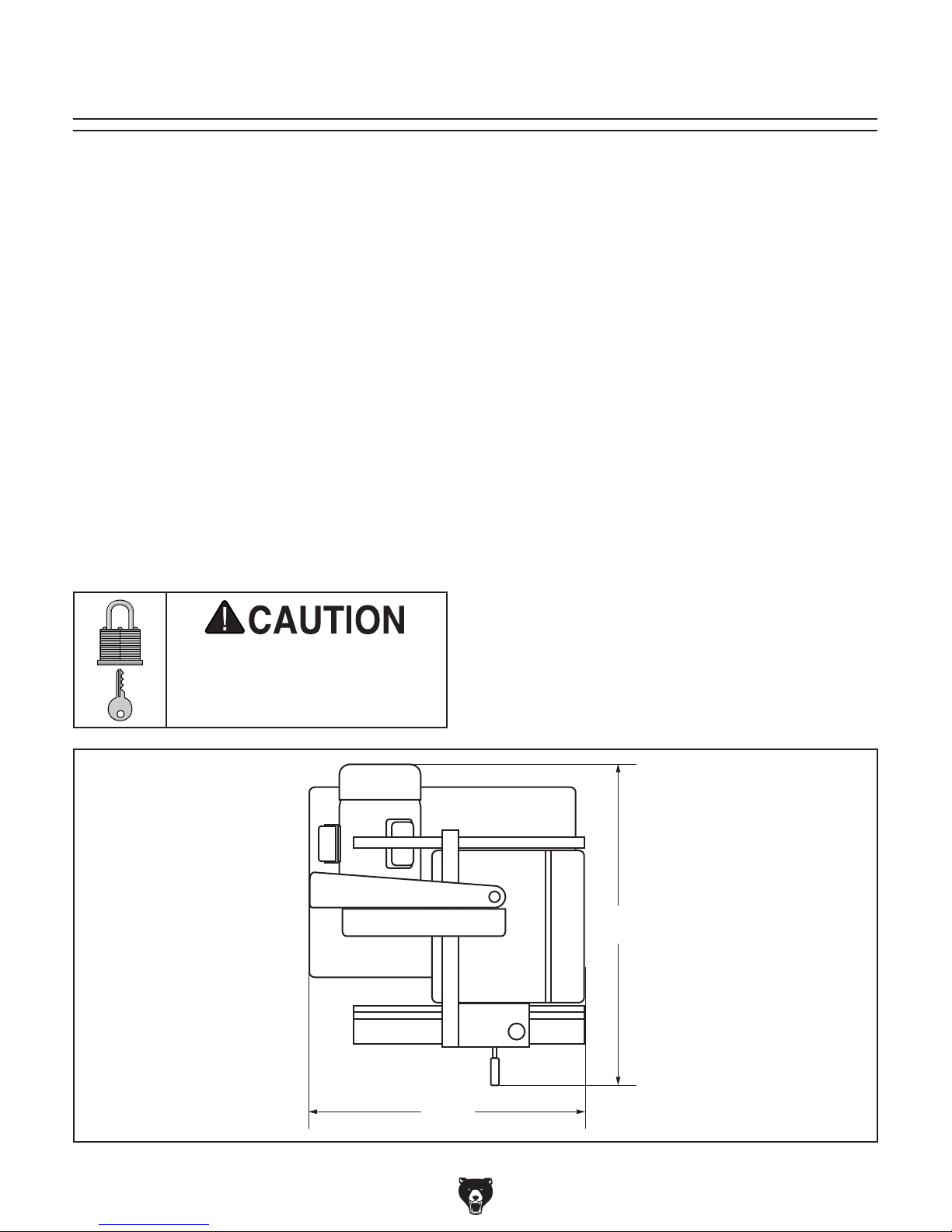
Space Allocation
Consider the largest size of workpiece that will
be processed through this machine and provide
enough space around the machine for adequate
operator material handling or the installation of
auxiliary equipment. With permanent installations,
leave enough space around the machine to open
or remove doors/covers as required by the maintenance and service described in this manual.
See below for required space allocation.
Physical Environment
Extreme conditions for this type of machinery are
Place this machine near an existing power source.
other hazards. Make sure to leave enough space
Shadows, glare, or strobe effects that may distract
or impede the operator must be eliminated.
Machine Data Sheet for the weight
Children or untrained people
may be seriously injured by
this machine. Only install in an
access restricted location.
The physical environment where the machine is
operated is important for safe operation and longevity of machine components. For best results,
operate this machine in a dry environment that is
free from excessive moisture, hazardous chemicals, airborne abrasives, or extreme conditions.
generally those where the ambient temperature
range exceeds 41°–104°F; the relative humidity
range exceeds 20%–95% (non-condensing); or
the environment is subject to vibration, shocks,
or bumps.
Electrical Installation
Make sure all power cords are protected from
traffic, material handling, moisture, chemicals, or
around machine to disconnect power supply or
apply a lockout/tagout device, if required.
Lighting
Lighting around the machine must be adequate
enough that operations can be performed safely.
Figure 5. Minimum working clearances.
-16 -
26"
30"
G0555X (Mfd. Since 9/17)
Assembly
The machine must be fully assembled before it
can be operated. Before beginning the assembly
process, refer to
and gather
all
To ensure the assembly process
goes smoothly, first clean any
covered or coated in heavy-duty rust preventative (if
applicable).
listed items.
Needed for Setup
parts that are
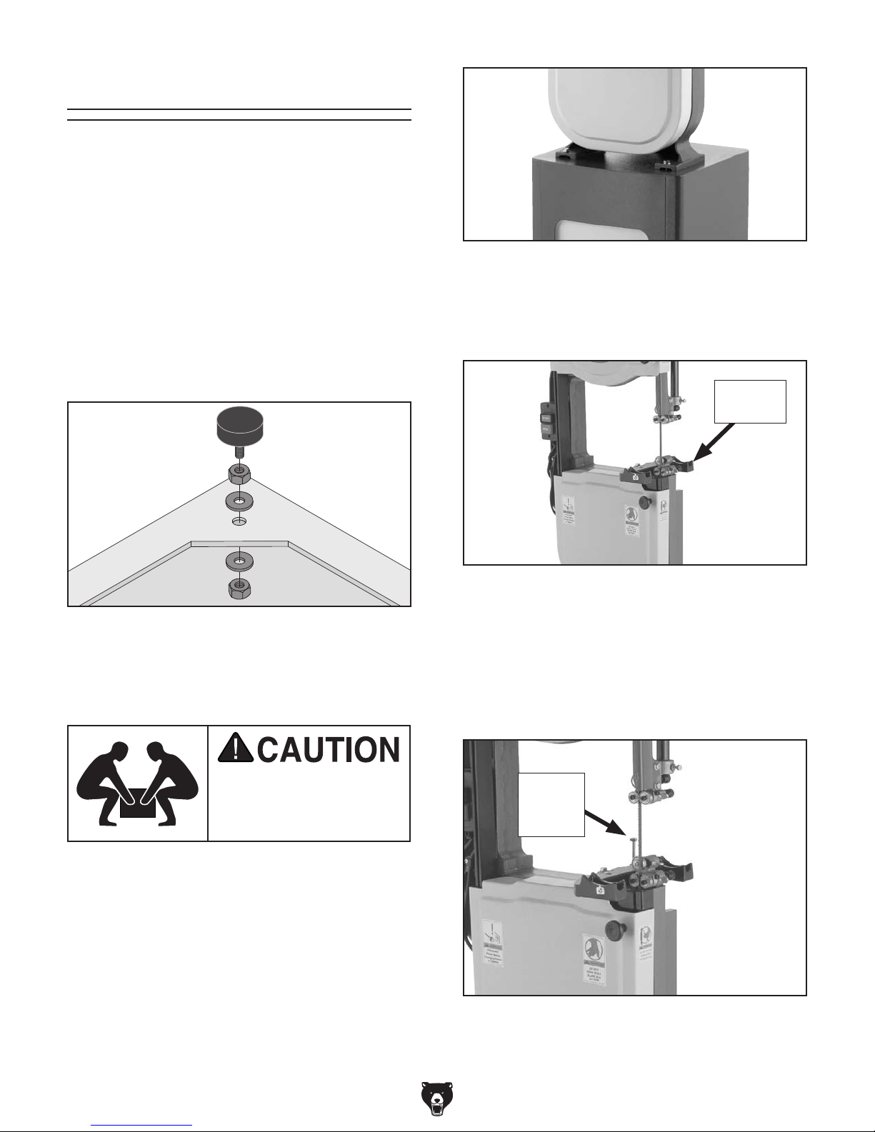
Figure 7. Bandsaw mounted to stand.
To assemble bandsaw:
1. Install rubber feet into bottom of cabinet
3
stand, as shown in Figure 6, with
⁄8-16 hex
nuts and 10mm flat washers.
Foot
Hex Nut
Flat
Washer
Flat
Washer
Hex Nut
Figure 6. Rubber foot order of installation.
2. Level cabinet stand by adjusting feet up or
down, then tighten hex nuts against stand to
secure feet in place.
6. Fasten trunnion base to bandsaw, as shown
in Figure 8, with (2) M8-1.25 x 30 hex bolts
and (2) 8mm lock washers.
Trunnion
Base
Figure 8. Installing trunnion base.
7. Thread (1) M8-1.25 hex nut halfway up
M8-1.25 x 80 hex bolt.
8. Thread the M8-1.25 x 80 hex bolt (a.k.a.
positive stop bolt) into trunnion base so it is
installed similar to Figure 9.
The bandsaw is heavy
and awkward to lift. Get
assistance from another
person when lifting.
3. Get an assistant to help you lift the bandsaw
and place it on top of the stand.
4. Line up mounting holes on bandsaw base
with those on stand.
5. Secure bandsaw to stand with (4) M8-1.25 x
35 hex bolts, (8) 8mm flat washers, (4) 8mm
lock washers, and (4) M8-1.25 hex nuts (see
Figure 7).
G0555X (Mfd. Since 9/17)
Positive
Stop
Bolt
Figure 9. Shows positive stop bolt installed.
-17-
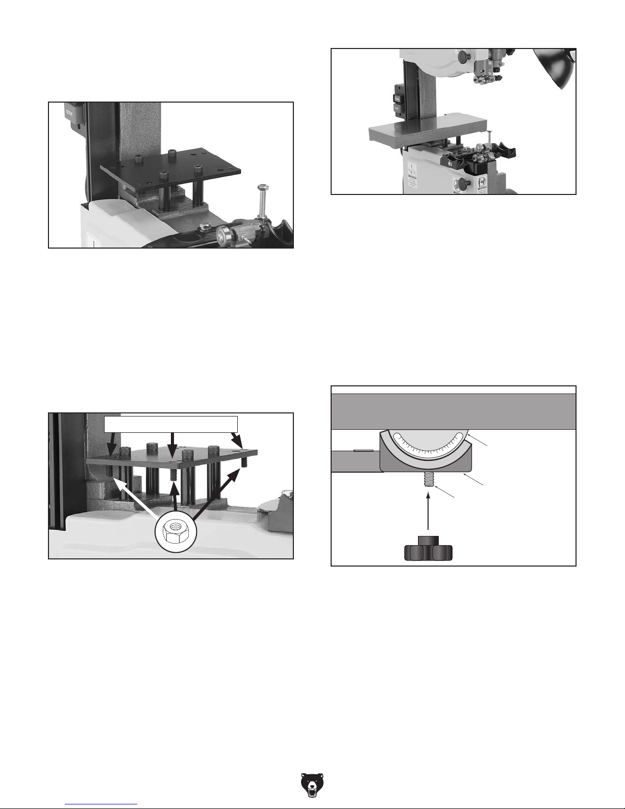
9. Attach lever board to bandsaw body with (4)
spacers and (4) M8-1.25 x 60 cap screws, as
shown in Figure 10.
Figure 10. Lever body attached.
10. Thread four set screws into lever board from
underneath until they are flush with top of
lever board (see Figure 11), then thread
M8-1.25 hex nuts up set screws and against
lever board.
Note: The hex nuts act to lock the set screws
in place once they are positioned, so they do
not vibrate loose during operation.
Figure 12. Extension table installed.
12. Remove table insert from center of table and
remove table pin from end of table slot.
13. Fit table around blade and rest table trunnions on trunnion base, making sure trunnion
bolts are hanging out of bottom of trunnion
base.
14. Thread (2) M10-1.5 knobs onto the trunnion
bolts hanging through bottom of trunnion
base, as illustrated in Figure 13.
Set Screws Flush w/Top
Figure 11. Set screws installed in lever board
(3 of 4 shown).
11. Attach extension table to lever board with (4)
M6-1 x 25 cap screws, (4) 6mm flat washers,
and (4) 6mm lock washers (see Figure 12).
Only thread cap screws in halfway for now
(adjustments to extension table will be made
later).
Table
Table Trunnion
Trunnion Base
Trunnion Bolt
Figure 13. Table installation on trunnion base.
15. Place table insert in center of table, so it sits
flush with table top surface.
16. Insert pin into end of table slot.
-18-
G0555X (Mfd. Since 9/17)
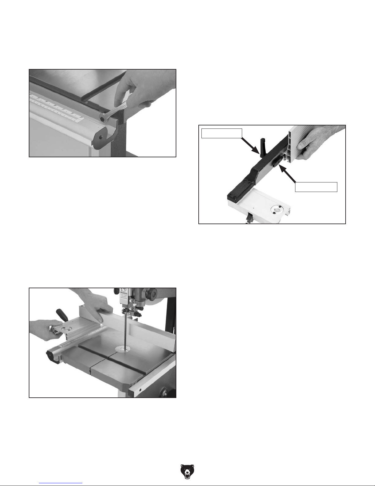
17. Fasten front fence rail to front of bandsaw
table with (2) M6-1 x 20 hex bolts, (2) 6mm
lock washers, and (2) 6mm flat washers, as
shown in Figure 14.
Figure 14. Fastening front fence rail to table.
18. Fasten rear fence rail to back of bandsaw
with (2) M6-1 x 16 cap screws.
19. Thread M8-1.25 hex nut from hardware bag
onto fence handle threads, then thread fence
handle into fence.
22. Push fence handle down to lock fence in
position.
23. Insert lock handle with washer through hole
in fence and attach moving plate (see Figure
16) on other side.
24. Slide resaw fence over moving plate as
shown in Figure 16. Center it with original
fence, then lock it in position by tightening
lock handle.
Lock Handle
Moving Plate
20. Tighten hex nut (already on the fence handle
threads) down to fence body to keep fence
handle from rotating.
21. Pull fence handle up and place fence on the
front fence rail, as shown in Figure 15.
Figure 15. Installing fence onto rails.
Figure 16. Installing resaw fence.
25. Install a light bulb that is rated for the wired
voltage of the machine. The bulb must not
exceed 60W.
G0555X (Mfd. Since 9/17)
-19 -
 Loading...