

Page 1
GRINDMASTER CRATHCO SYSTEMS, INC.
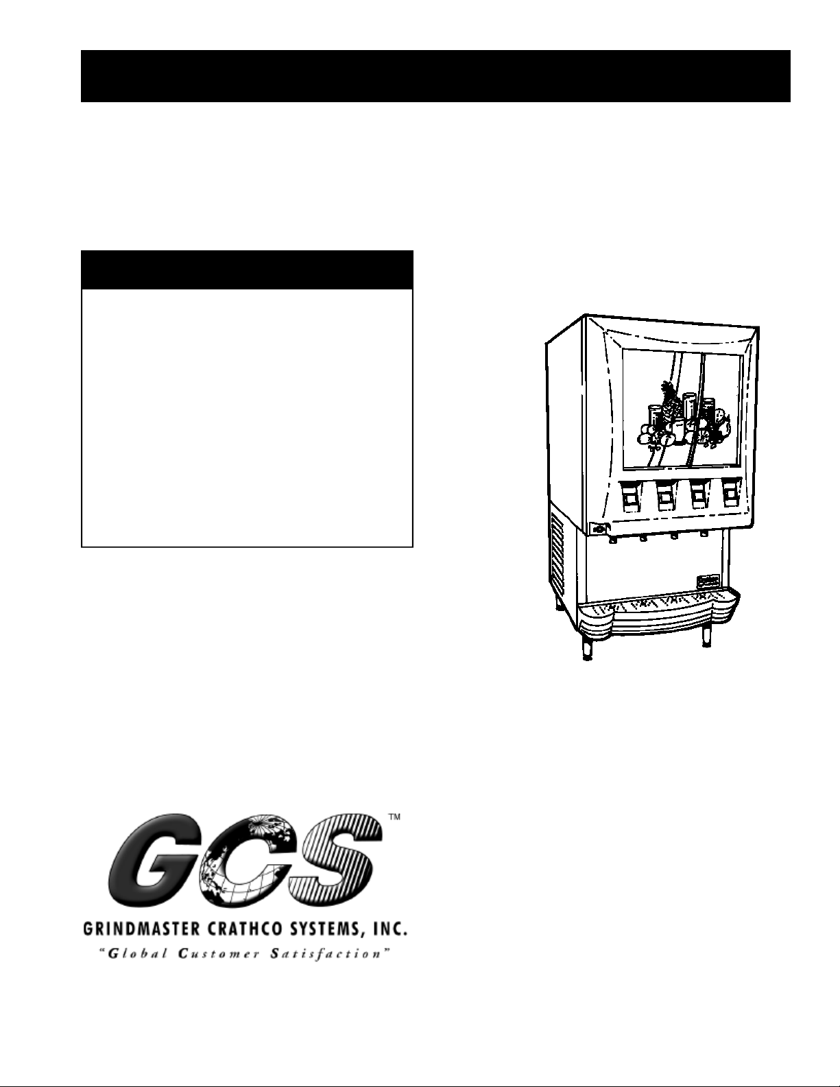
Crathco®Post Mix Beverage Dispensers
Operation and Instruction Manual
Model PM4-B & PM45-B
TABLE OF CONTENTS
Warnings and Safety Precautions..................2
Installation ..................................................3-5
Operating and Adjustments.........................5-7
Care and Cleaning......................................7-9
Maintenance Service ................................9-10
Troubleshooting.......................................11-16
Exploded Views ......................................17-23
for
Electrical Diagrams.................................24-25
Refrigeration Diagram..................................26
Prior authorization must be obtained
from Grindmaster Crathco Systems for all warranty claims.
MODEL PM4-B
480 Neponset Street
Canton, MA 02021 USA
(617) 828-1250
FAX (617) 828-9617
www.grindmaster.com
Grindmaster Crathco Systems, Inc., 2000
PRINTED IN THE USA
0700 Form # CC-398-03
Part # 9408
Page 2
WARNING LABELS AND SAFETY PRECAUTIONS
OPERATOR'S SAFETY PRECAUTIONS
1. Read and understand the operating instructions in this manual thoroughly.
2. Note all warning labels. If any of the warning labels are missing or damaged replace them immediately.
3. Keep operating area clean.
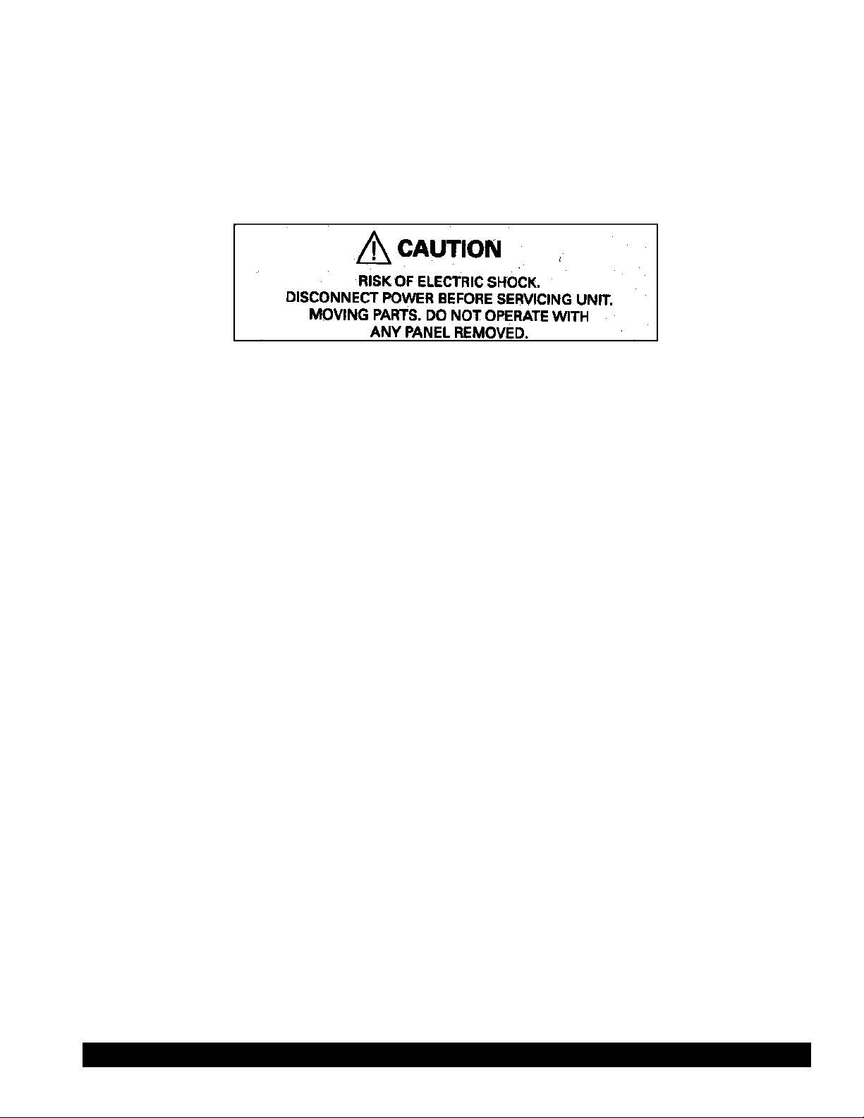
Located on the top of the condenser shroud and on the rear panel.
INTRODUCTION
The GRINDMASTER CORPORATION dispenser is a unique, self contained, counter top style unit with high
capacity self-adjusting cooling systems. Both cooling systems: patented cabinet cooling system and ice-bank
water cooling system do not require manual adjustment or settings. There are no Electromechanical thermostats
to control the cooling systems.
The cabinet cooling system is a frost-free system that maintains not only desired temperature, but also a constant
humidity level in the cabinet with exception to the time when the cabinet door is open.
The dispensing buttons are located on the front panel, and are easily accessible by the operator. The system is
powered with safe 24 VDC as well as a water inlet solenoid valve and an electronic controller.
The machine has accessible modular construction and has been designed to be simple, yet effective, to provide
many years of trouble-free operation.
Page 2 Crathco® Post Mix Beverage Dispensers
Page 3

INSTALLATION
Installation Notice
A water filter is recommended for the water supply to the dispenser, especially in areas where water contains a
high level of minerals such as calcium or other solids. Over long periods of time, calcium deposits build on
heat-exchanger coils and will lower the cooling capacity of the system. Calcium build up will also occur on the
strainers enclosed in the dispensing valves.
The cooling system is provided with copper coils, designed to last the life of the dispenser. However, some
chemicals in treated or not treated water, specifically chlorine and sulfur (sulfide) may shorten the life of the coils.
The initial investment in the filtering system will pay for itself in quality and by ensuring longer life for the
machine.
Unpacking
1. With the unit upright, remove staples from the box at the very bottom around perimeter of the box and on the
top of the box.
2. Open the top of the box and remove the accessory box.
3. Slide the box tube upward exposing the machine.
4. Remove supporting corners and front supporting block.
5. The unit must have the legs installed upon removal from the packaging. Legs are supplied in the acces-
sory kit (box on top of the machine in the packaging.)
Failure to install the legs will cause the dispenser refrigeration system to work improperly and burn out as
well as possibly damage the water inlet valve.
6. Support all 4 sides, lift and place in an appropriate area. (See location below)
Installing Your Unit
CAUTION: DO NOT ALTER OR DEFORM THE PLUG IN ANY WAY!
!
ALTERING OR DEFORMING THE PLUG MAY DAMAGE UNIT AND WILL VOID WARRANTY!
1. Location
Position dispenser in a well-ventilated area indoors. Avoid exposure to direct sunlight and/or heat caused
by radiation. Ambient room temperature must be in the range of 60Þ - 90ÞF (15-32ÞC). Do not install unit
in an enclosed area where heat build up could be a problem.
Note: Air flow direction and spacing required on Figure B page 4.
2. Plumbing
Connect the dispenser to cold, potable water source suitable for drinking.
Do not install unit on a water softener/softening line. For proper operation incoming supply water pressure
must be in the range 29 psig (2 - 2.75 bar), therefore a water pressure regulating valve is recommended.
3. Electrical
This unit is supplied with a 6” (2m) long 2 wire plus ground power cord. The PM45-B connector is suitable
for standard single phase 220V/50Hz power supply. PM4-B models should be connected to a 115V 60 Hz
power supply. This cord exits the unit out the bottom of the base and should be routed per National Electric
Code.
Crathco® Post Mix Beverage Dispensers Page 3
Page 4
WARNING: Only a qualified service technician should service internal electrical components.
Installing Your Unit (cont.)
4. Water Hook-up.
It is recommended to provide water connection to the dispenser from a dedicated
water line. Without this, consistent water pressure necessary to sustain proper brix
levels may not be maintained due to water surges caused by other water-consuming equipment, such as dishwashing machines, other dispensing equipment, coffee
machines etc!
The water line supply should be at least 3 2/5” (8 mm) internal diameter and must
be rated for 217 psig (15 bar) pressure at 70ÞF (21°C) water temperature.
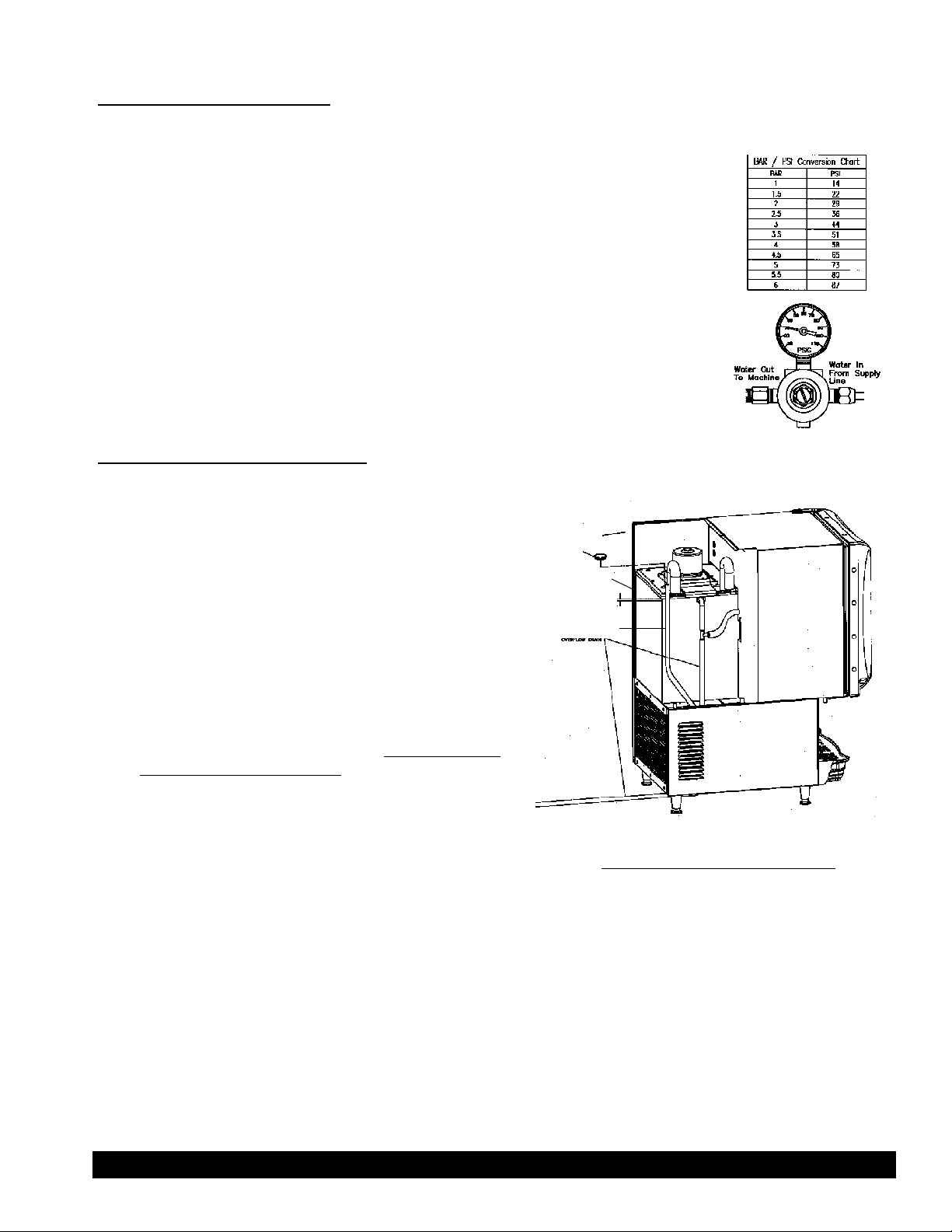
Install a water pressure regulator gauge at the inlet to the machine and set it to
29 Psig (2 bar). The water pressure regulator gauge, is included in the Accessory
Box. It is important that the gauge is installed accordingly. (See figure A) Failure to
comply will damage the gauge and render it inoperable.
Filling the Ice bank with Water
1. Remove the rear upper panel from the dispenser.
(Figure A)
2. Find the Ice Tank Plug (round black rubber plug
about 1” (2.5 cm) diameter) on the top of the ice
Back of unit
Ice Tank Plug
bank cover and remove it.
Water Level
3. Use the water hose or funnel to fill the tank with cold
tap water (18 liters.)
4. Stop filling water once water is flowing from overflow
1.5 cm below top
cover
Water Level Gauge
Overflow
Drain
drain.
5. Look at the water level gauge (tank drain clear hose
attached to the insulated refrigeration line in upright
position.) The water level in the tank is equal to the
Air Out
›
›
›
water level in the water gauge and should be about
1.5 cm below ice bank cover. *(see Figure B)
6. Replace rubber plug and rear upper panel.
7. Turn the power switch ON.
(Figure B)
›››
Air In
Minimum Air Space Requirements
Top 12”
*To assure the proper operation of the dispenser, the water level in the
ice bank must be kept at the full fill level explained above. Water level
Sides 2”
Back 4”
in the ice bank should be checked every couple of months.
WARNING: Do not remove the water level gauge from its position unless you want to drain the water
from the ice bank.
Note: If the water level in the ice bank falls substantially (about 2”/5 cm), the refrigeration system will stop
operating. Before this happens, the loss of cabinet cooling will be observed.
Page 4 Crathco® Post Mix Beverage Dispensers
Page 5
Installation (cont.)
POWER SUPPLY: 220 VAC 50 Hz 115/60Hz
COMPRESSOR: HP: 1/4, (630 Kcal, 2500 BTUH)
REFRIGERANT: R134a 260 grams/9.1 oz.
DESIGN LOW PRESSURE: Max. 9.5 BAR; 140 PSIG
DESIGN HIGH PRESSURE: Max. 16.3 BAR; 240 PSIG
SYSTEM TYPE: CAPILLARY TUBE, HERMETIC
IDLE POWER CONSUMPTION .5A .8A
RUN POWER CONSUMPTION 4A, 5A (MAX) 7A, 8A (MAX)
FUSE SIZE 6 A Slow Blow Controller
DISPENSING RATIO 50 ML/SEC
SUPPLY WATER PRESSURE 2 - 2.7 BAR; 29-40 PSIG
WORKING AMBIENT TEMPERATURE 15.5°C - 32.2°C 60-90ÞF(guaranteed performance)
PRODUCT STORAGE CAPACITY NOM. 4 LITERS (FOUR 1L TETRAPACK)
Specifications: PM45-B PM4-B
OPERATING AND ADJUSTMENTS
Explanation of terms
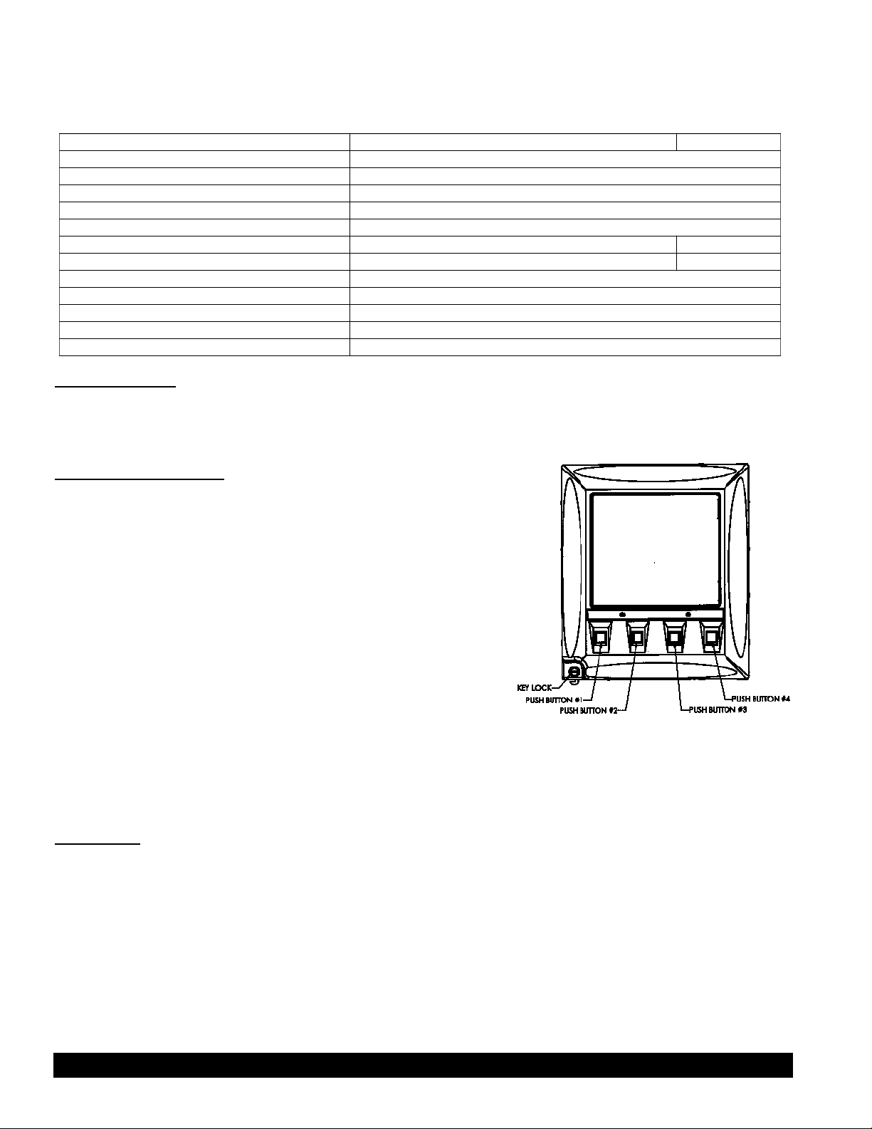
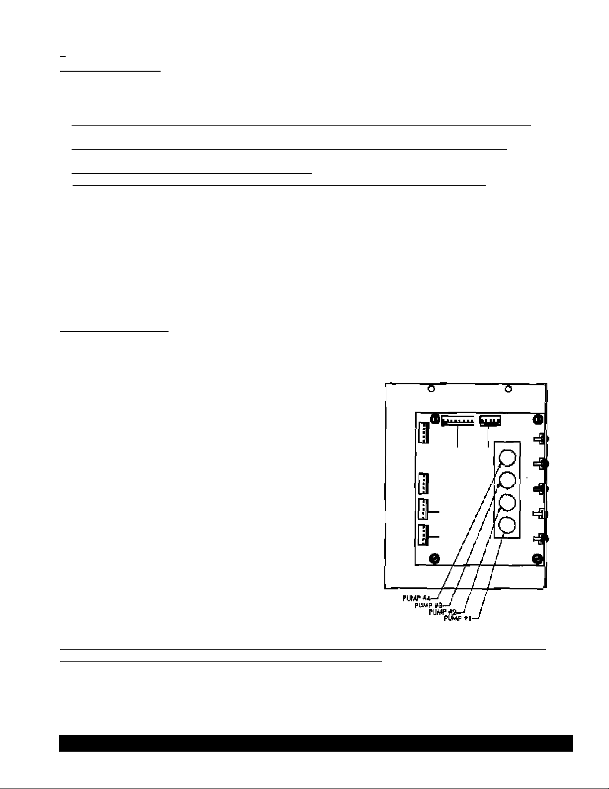
All descriptions related to dispensing heads, dispensing buttons,
pump motors such as: push button #1, dispensing head #2, pump
motor #3 etc. are used in relation to the front of the machine. This
relates also to all components inside of the machine that are
symmetrically positioned. (See Figure C)
For example:
Push button #1 - Far left positioned dispensing push button.
Push button #4 - Far right positioned dispensing push button.
Dispensing head #3 - All components involved when dispensing
caused by depressed push button #3.
Pump motor #4 - Pump motor that works when push button #4 was depressed and is positioned inside the
machine in line with push
button.
(Figure C)
Brix Setup
If initial concentrate brix is 60 and required mixing ratio is 6+1/6:1 (6 ounces water to one part concentrate),
then brix of ready to drink mixture of a concentrate and water should be 10.
To measure brix level, a refractometer is used to show sucrose content in a drink by measuring change of the light
diffraction in the water caused by change of viscosity due to sucrose content.
The correct ratio is achieved by controlling water and a concentrate flow to the mixing device, in this case mixing
chamber. Brix on each dispensing head is preset in the factory. In the field, the brix needs to be fine-tuned to the
Crathco® Post Mix Beverage Dispensers Page 5
Page 6
correct value with the use of a refractometer. Setting brix by taste is an acceptable method and usually gives
+ 0.5-0.8 brix error.
Brix Setup (cont.)
Mixing water with a concentrate in this dispenser was designed at the following conditions:
1. The initial temperature of a concentrate (syrup) used in the dispenser should be 39-41ÞF (4-5°C).
2. The initial temperature of the water supplied by the dispenser cooling system is 39ÞF (4°C).
3. The static water pressure should be set to 29PSIG.
The pressure regulator gauge should show 29PSIG (2 bar) when there is no water flow.
It is very important to apply the concentrate at the noted temperature since a concentrate changes its viscosity
when it cools down. A dramatic change of the viscosity (thickness of concentrate) causes the pumps capacity to
change resulting in the need to readjust the brix level.
The machine provides cooling to keep syrups or concentrates in the correct temperature. If the initial temperature
of syrup or concentrate is the room temperature when the brix is set, after approximately one hour the syrup or
concentrate will be cooled down to 39-41ÞF (4-5ÞC). As a result your brix setting will change. Therefore it is recommended that syrup or concentrate should be refrigerated prior to setting brix.
Brix Set Procedure
The brix number for given flavors is shown in the table. If the table does not include information for a particular
flavor, temporarily use the taste method and request information from a concentrate supplier.
Assuming that correct temperature of orange concentrate is applied
to the first dispensing head and syrups are applied to the remaining
dispensing heads proceed as follows:
1. Set the water pressure to 2 bar (29 Psig) static.
2. Depress chosen dispensing push button and hold until water
from the dispensing nozzle changes color.
3. Release push button. Depress push button again dispensing
drink into the cup.
4. Measure a brix level. If the brix is too rich (higher number
than expected) the concentrate pump needs to be slowed
down by turning corresponding potentiometer on the controller
board counterclockwise (potentiometer called Pump #1 on the
controller board corresponds with push button #1 and so on.)
The controller board can be found on the right hand side in the front
of the machine behind the splash panel. If potentiometer is already
all the way to the left, the water pressure must be increased
assuming that a concentrate temperature is at 39-41ÞF (4-5° C). Please, note that water pressure change will
cause brix change on other dispensing heads if they were set previously. (See figure D)
(Figure D)
If brix is too weak the pump speed must be increased by turning the corresponding potentiometer clockwise.
If there is problem setting up brix, refer to brix problem troubleshooting.
Page 6 Crathco®Post Mix Beverage Dispensers
Page 7

Once the brix is set, use the same flavor set up on each dispensing head. The flavor used on a particular
dispensing head can be changed if the brix and viscosity of the syrup remains the same.
Dispenser Operation Tips
1. To dispense the drink, depress and hold dispensing push button as long as needed.
2. After dispensing 2 liters consecutively allow a 15-30 second idling time before next usage.
3. Keep dispenser door closed and do not allow it to be open for a longer time than necessary.
4. Avoid a concentrate spillage inside the cabinet. If spillage occurs, clean immediately. If spillage is left
unattended, over time it will dry out and be difficult to clean.
Care and Cleaning
Flushing the Dispensing System.
1. Open the door cabinet and turn the flush switch to the FLUSH
Dispense
FLUSH
position. The flush switch is located on the inside wall of the
door and is labeled:
(Figure E)
By turning the switch to the FLUSH position the product pumps are disabled. The machine now can
dispense water only.
2. Close the door and depress the far left dispensing switch for 30 seconds. Repeat this operation with all
remaining dispensing switches.
3. Open the door and turn the flush switch to the DISPENSE position.
The flushing operation rinses the mixing chamber, static mixer, and dispensing nozzle. The flushing
operation is required every day at closing or when the machine will not be in use for more than four hours.
Note: Flushing the dispensing system does not cause loss of cooling capacity.
Washing Parts
Parts such as the dispensing nozzle, static mixer and pick up tube assembly must be washed consistently every
week to remove possible product build up. This will help to assure the correct mixing and dispensing of product
especially when the product contains a pulp.
Removal of these parts does not require use of any tools. This is a simple hand operation and requires luke warm
water and dishwashing detergent.
1. Flush dispensing system first.
Crathco® Post Mix Beverage Dispensers Page 7
Page 8
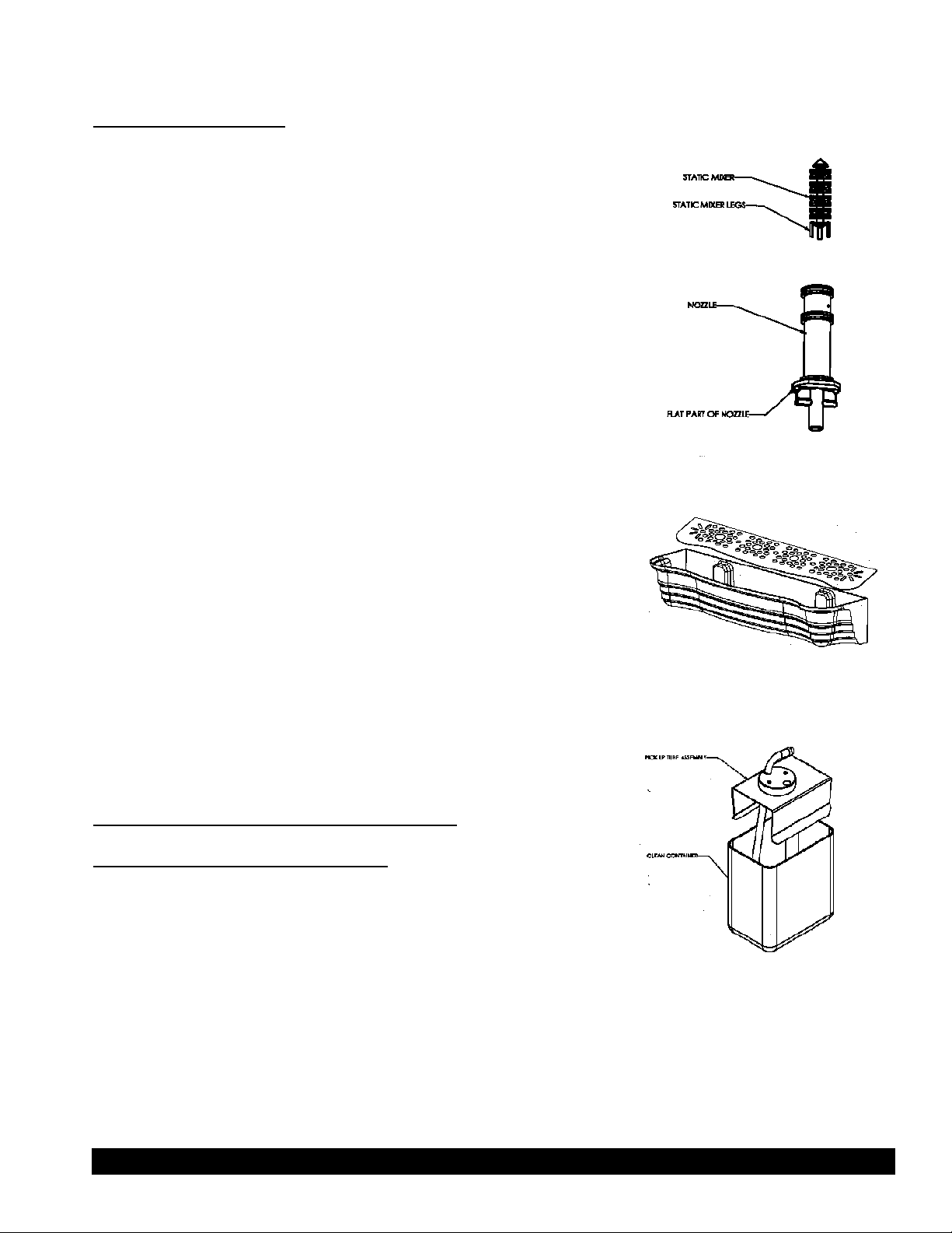
Washing Parts (cont.)
2. Remove the dispensing nozzle from the machine by turning it 90° to the
left or right side, pulling it down. If there is a
problem pulling it down, turn the nozzle with quick short left to right and
back motions pulling it down at the same time. Make
sure that the nozzle is in the proper position. The flat part of the thin round
plate should be between
screw heads. Remove product pick up tubes from the product containers.
Note: Static mixer is inside the nozzle. If static mixer is lost, the product will not
mix properly. (See Figure F.)
3. Turn the dispensing nozzle upside down and remove static mixer.
Repeat the same with all remaining nozzles.
- - - -
4. Wash the parts with water mixed with hand dishwashing detergent.
5. Rinse all parts thoroughly, put static mixers into nozzle leg first and
install them back in the machine by inserting
into mixing chambers and locking
in positions. Failing to lock in position may cause dispensing nozzle with the
static mixer to be pushed rapidly out of the mixing chamber by the 29
Psig
(2
bar)
water
pressure and splash all surrounding with
mixed product. Replace product pick up
tubes.
Note: Wash on a regular basis the drip tray and the drip tray grill separately. (see figure G)
Sanitizing and Cleaning Dispensing System
Product Pumps System Cleaning
(Figure F)
(Figure G)
The product pumps system cleaning assures the performance of the pumping system and cleans the inside walls of tubing.
The product used is very thick (6+1 concentration or more) and will build up
a layer of sucrose and pulp mixture on the inside walls of tubing. This build up
narrows the inside diameter of the tubes and will restrict the product flow and
will slowly offset the brix. Proper cleaning of the pump system will help prevent and correct this condition.
1. Remove the product containers from the dispensing cabinet. Replace each container with any clean contain-
er (same capacity as product container) filled with warm water (40-45°C) and insert product pick up tubes
Page 8 Crathco® Post Mix Beverage Dispensers
(Figure H)
Page 9

into clean container. (see figure H)
2. Close the cabinet door and dispense the warm water the same way, as it would be a product. Dispensing
should last for no longer than 90 seconds.
3. Repeat the above for all remaining dispensing stations.
Washing Parts
Proceed as described in “Wash Parts” without flushing.
Sanitizing
Prepare sanitizing solution per instruction on the package changing the strength of the solution to be equivalent to
6+1 e.g. If instruction calls to dilute contents of the sanitizer package in 4 liters of water use only 0.6 liters of the
water for the solution. Fill the clean container that was used for tubing cleaning with the sanitizing solution.
1. Install container with sanitizer solution in the cabinet and connect pump tubing to product pick up tube assembly.
2. Close the cabinet door and depress dispensing switch corresponding with position of the container with
sanitizing solution for 15 seconds.
3. Wait 3 minutes.
4. Lift the pick up tubes assembly to be above the sanitizing solution and depress the same dispensing switch
for 2 seconds to avoid sanitizer spillage inside of the cabinet. Rinse the pick up tube assembly and connect it
back to the pump tubing.
5. Replace the container containing the sanitizing solution with the product container.
6. Depress dispensing switch. Keep dispensing product until 200 ml is dispensed with correct brix.
7. Repeat steps 1 to 6 for all remaining stations.
8. Turn the flush switch to FLUSH and depress each dispensing switch for 4 seconds.
Note: Do not skip any sanitizing procedure step.
Flushing
Proceed as described in Flushing the Dispensing System. Flushing
time is only 4 seconds.
Preventing Unauthorized Dispensing During “Off
Hours”
After system flushing, do not turn the flush switch to the DISPENSE
position. Lock the door and remove the key from the lock. This will
allow dispensing cold water only. (See figure I)
Note: Turn the flush switch to DISPENSE when resuming operation
the next day.
Back of unit
Ice Tank Plug
Water Level 1.5
cm below top
cover
Water Level
Gauge
Overflow
Drain
Air Out
›
›
›
(Figure I)
›
(Figure J)
Air In
›
›
Crathco®Post Mix Beverage Dispensers l Page 9
Page 10

MAINTENANCE
Daily:
System Flushing (See pages 7-8)
Weekly:
System flushing and washing (See pages 8-9)
MAINTENANCE (cont.)
Biweekly:
Sanitizing (See page 8-9). Ice bank water level check up. (See figure J)
Note: Make sure that water level in the drain tube is even with tank overflow outlet.
Monthly:
1. Check the condenser for dust build up. If necessary clean the condenser with a bristle brush.
2. After sanitizing, remove dispensing base assembly and wipe off the interior of the cabinet with a cloth
dampened in sanitizer.
3. Check the platform of the dispensing base assembly and clean it using sanitizer solution. Replace
dispensing base assembly.
4. Clean cabinet cooling system drain with a small bottle brush and sanitizer solution.
5. Check water level to ensure it is maintained at aproper fill level (See page 4). Filling the ice bank with water.
Every half of the year:
1. Replace all pump tubing. If pumps are loosing their capacity and adjusting pump speed does not correct the
problem, replace tubing on a more frequent basis.
2. Remove cabinet cooling system and wash it. Remove cooling fan prior to washing. If necessary separate the
cooling coil from the plastic shroud and wash them separately. Rinse
thoroughly both parts. Wipe off plastic shroud with dry cloth. Replace the
cooling system.
Every two years:
Inspect pump housings and pump rollers. Clean inside pump housings.
Merchandiser Bulb Replacement
WARNING: Disconnect machine from branch electrical supply before
changing the light bulb.
1. Remove merchandiser graphic by pushing its edge towards the center
of the merchandiser causing it to bow.
2. Repeat the same with clear plastic graphic reinforcement.
3. Remove the old light bulb by gently turning the lightbulb 1/4 turn to the
left and pulling the bulb from the socket. (See figure K)
4. Install the new bulb by lining up the pins on either end of the bulb parallel with the socket opening.
5. Gently insert both ends of the bulb into the socket and turn the bulb 1/4 turn to the right until the bulb locks
into place.
6. Replace the merchandiser photo and cover.
(Figure K)
Page 10 Crathco®Post Mix Beverage Dispensers
Page 11

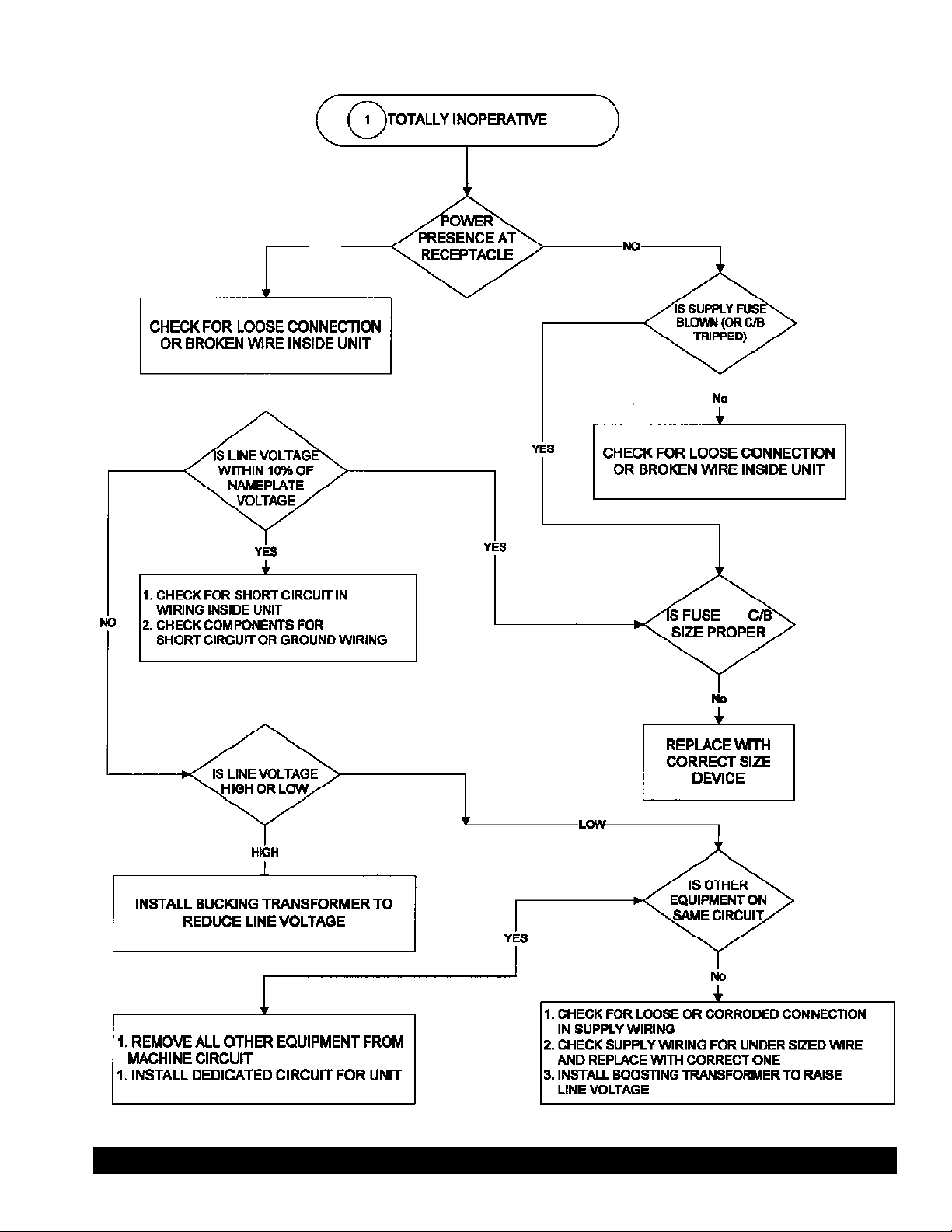
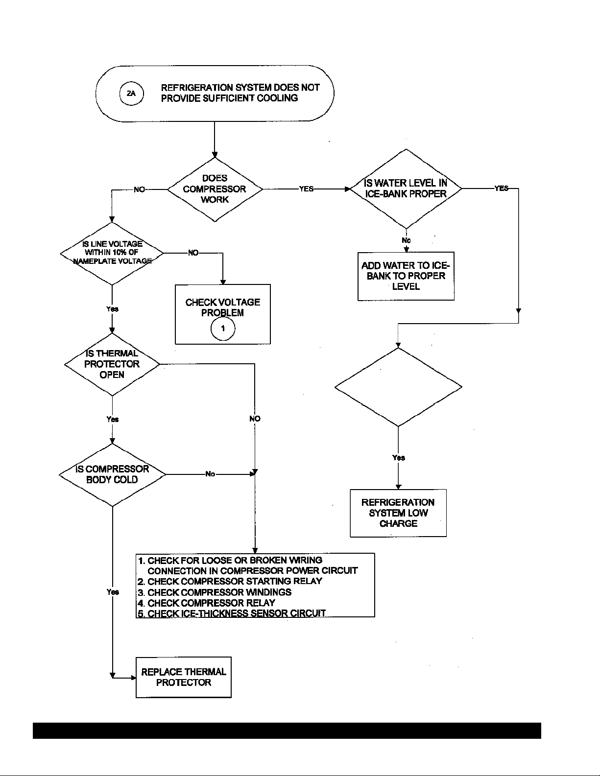
TROUBLESHOOTING
WARNING: Only a qualified service technician should perform Electrical and mechanical adjust-
ments of repairs. Always disconnect power before attempting any maintenance procedures.
UNIT DISPENSES POOR BRIX DRINK
OR SYRUP/CONCENTRATE ONLY
IS
THE DOOR
MERCHANDISER
LIGHT ON
Crathco® Post Mix Beverage Dispensers Page 11
Page 12
Post Mix Beverage Dispensers
TROUBLESHOOTING (con’t.)
YES
Page 12 Crathco®
Page 13
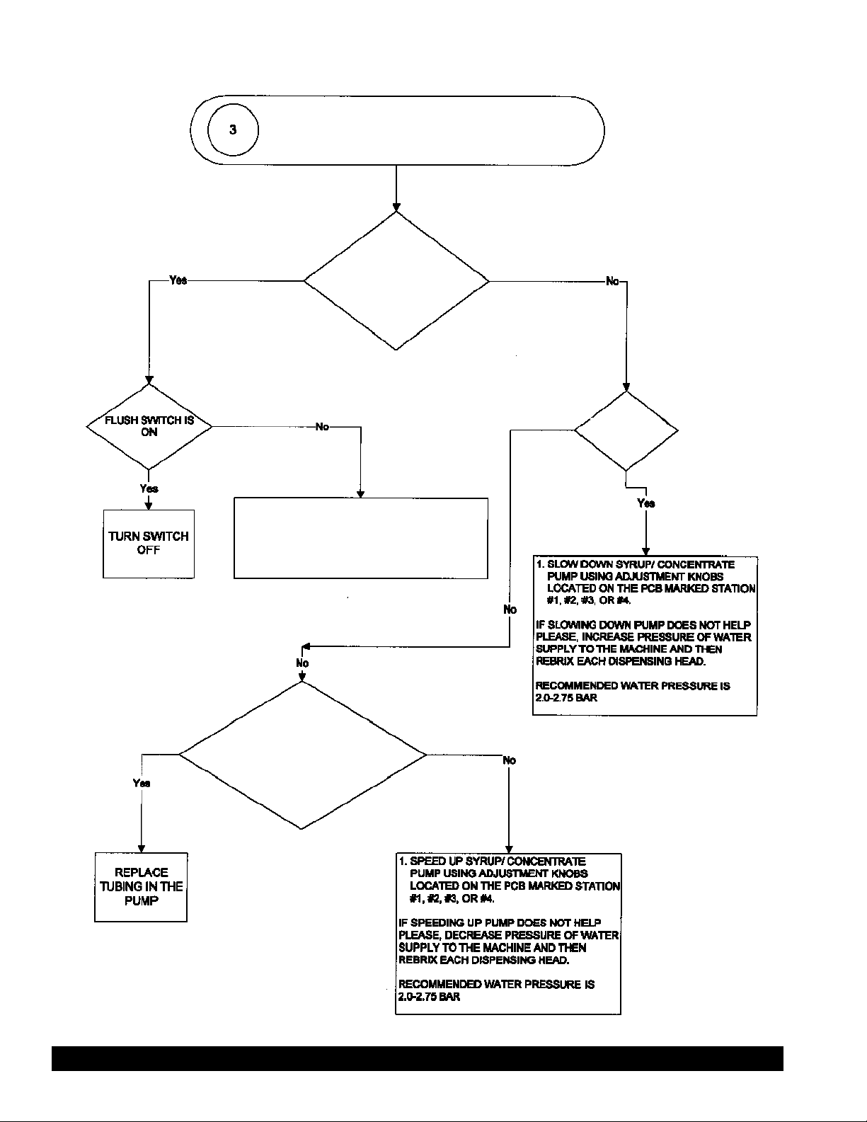
TROUBLESHOOTING (con’t.)
DOES
ICE-BANK HAVE NO
ICE OR PARTIAL ICE
AROUND
COIL
Crathco®Post Mix Beverage Dispensers Page 13
Page 14

Post Mix Beverage Dispensers
TROUBLESHOOTING (con’t.)
Page 14 Crathco®
1. THERE IS RESTRICTION IN WATER
SUPPLY LINE OR IN THE COOLING COIL
2. POSSIBLE RESTRICTION AT THE SUCTION
SIDE OF THE WATER PUMP OR AT THE
DISCHARGE IN THE INSIDE OF THE
WATER
Page 15
TROUBLESHOOTING (con’t.)
UNIT DISPENSES POOR BRIX DRINK
OR SYRUP/CONCENTRATE ONLY
UNIT DISPENSES
SYRUP/CONCENTRATE
ONLY
IS DRINK
TOO RICH
1. CHECK CORRESPONDING
SOLENOID VALVE FOR POWER
SUPPLY OR MALFUNCTION
2. CHECK INLET SOLENOID VALVE FOR
POWER SUPPLY OR MALFUNCTION
TUBING IN PUMP HAS
OPERATED LONGER THAN 6
MONTHS OR WAS USED
EXCESSIVELY
Crathco® Post Mix Beverage Dispensers Page 15
Page 16

TROUBLESHOOTING (con’t.)
Page 16 Crathco® Post Mix Beverage Dispensers
Page 17
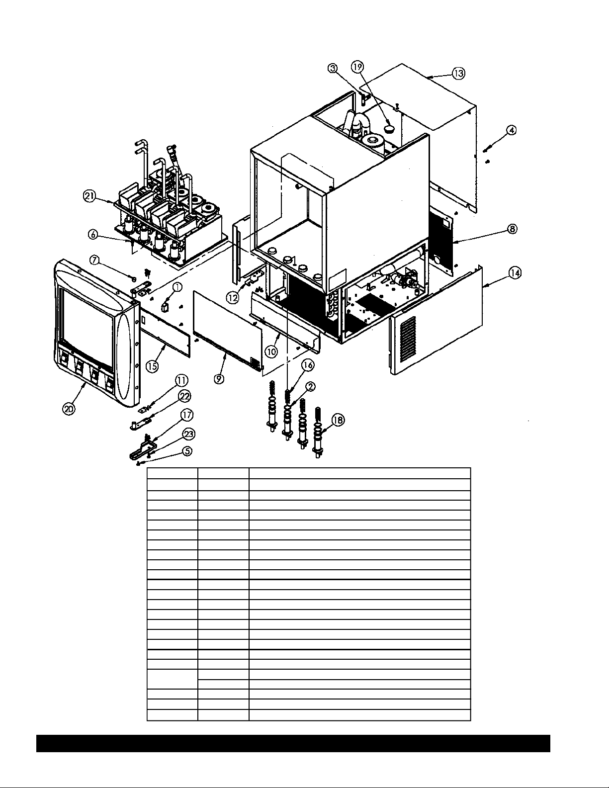
FINAL ASSEMBLY EXPLODED
ITEM P/N DESCRIPTION
1 3373 SWITCH, ROCKER
2 9105 O-RING, .864 ID X .070 W
3 9108 FITTING, 3/8 X 3/8 X /38 BARB PLASTIC TEE
4 9137 SCREW, 8-32 X 3/8 TAPTITE II SS BLACK
5 0069 SCREW, 8-32 X 1/2 PH TR HD TYPE F 410 SS
6 9110 SCREW, 8-32 X 5/8 PLAIN THUMB SS
7 9126 PLUG, HEYCO 2633
8 9304 PANEL, BACK LOWER
9 9307 PANEL, UPPER SPLASH
10 9308 PANEL, LOWER SPLASH
11 9311 SPACER, HINGE
12 9315 PLATE, DOOR GUIDE
13 9316 PANEL, BACK UPPER
14 9319 PANEL, SIDE
15 9322 PANEL, ACCESS
16 9803 MIXER, STATIC
17 9811 COVER, HINGE
18 9814 NOZZLE
19 9193 PLUG, ICEBANK LID
20 9213 MERCHANDISER DOOR ASSEMBLY, STD
21 9214 DISPENSING PLATFORM ASSEMBLY
22 9204 HINGE ASSEMBLY, DOOR
23 0073 SCREW, #10 PN HD PH ZINC
9233 MERCHANDISER ASSEMBLY
Crathco® Post Mix Beverage Page 17
Page 18

CONDENSING UNIT EXPLODED VIEW
31
ITEM P/N DESCRIPTION
1 1828 GROMET, COMPRESSOR 3250
2 1830 WASHER, COMPRESSOR
3 1831 CLIP, COMPRESSOR
4 9506 VALVE, INLET 2.2 GPM 24VDC
5 9517 TRANSFORMER 220VAC TO 28VAC, 150VA
9532 TRANSFORMER 115VAC TO 28VAC
6 3250 COMPRESSOR 240/220V 50 Hz
3247 COMPRESSOR 115V/60Hz
7 3371 CONDENSER
8 9521 BALLAST, LAMP F8T5 P/N 61118
8218 BALLAST, 120V
9 9522 RELAY, 12VDC COIL
10 9205 CONTROLLER ASSEMBLY
11 1000 SILENCER, FAN BLADE
12 1459 CONDENSER FAN BLADE
13 1584 FAN MOTOR 220V
1336 FAN MOTOR 115V
14 0055 NUT, FAN MOUNTING
15 9702 DRIER, SPORLAN C-03S
16 0057 NUT KEPS, 8-32
17 3370 BRACKET, CONDENSER FAN
18
ITEM P/N DESCRIPTION
18 9411 SCREW, #8 X 1/2 HEX HD SELF DRILL ZINC
19 9137 SCREW, 8-32 X 3/8 TAPTITE II SS BLACK
20 1783 POWER CORD, 1.5 M (NOT SHOWN) 220V
1072 POWER CORD 18-3 115V
21 9503 HARNESS, TRANSFORMER TO CONTROLLER 28 VAC (NOT SHOWN; SEE NOTE 1)
22 9507 HARNESS, COMPRESSOR RELAY COIL (NOT SHOWN; SEE NOTE 1)
23 9508 HARNESS, COOLING FAN (NOT SHOWN; SEE NOTE 1)
24 9509 HARNESS, FILL VALVE (NOT SHOWN; SEE NOTE 1)
25 9510 HARNESS, DISPENSE SWITCH (NOT SHOWN; SEE NOTE 1)
26 9512 HARNESS, DISPENSING CABINET (NOT SHOWN; SEE NOTE 1)
27 9514 HARNESS, TRANSFORMER TO TERMINAL BLOCK (NOT SHOWN; SEE NOTE 1)
28 9504 HARNESS, FLUSH SWITCH (NOT SHOWN; SEE NOTE 1)
29 9516 LEADS, LIGHT ASSEMBLY (NOT SHOWN; SEE NOTE 1)
30 9515 HARNESS, TERM BLOCK TO COMP. AND RELAY (NOT SHOWN; SEE NOTE 1)
31 8213 SWITCH, DOUBLE POLE ON/OFF
32 9166 GROMMET, SNAP IN HEYCO
33 9530 HARNESS, PWR SWITCH TO PWR CORD(NOT SHOWN; SEE NOTE1)
19
NOTES:
1) ALL HARNESS HOOK UP LOCATIONS
ARE DETAILED IN WIRING DIAGRAM P/N 9165
Page 18 Crathco® Post Mix Beverage Dispensers
Page 19
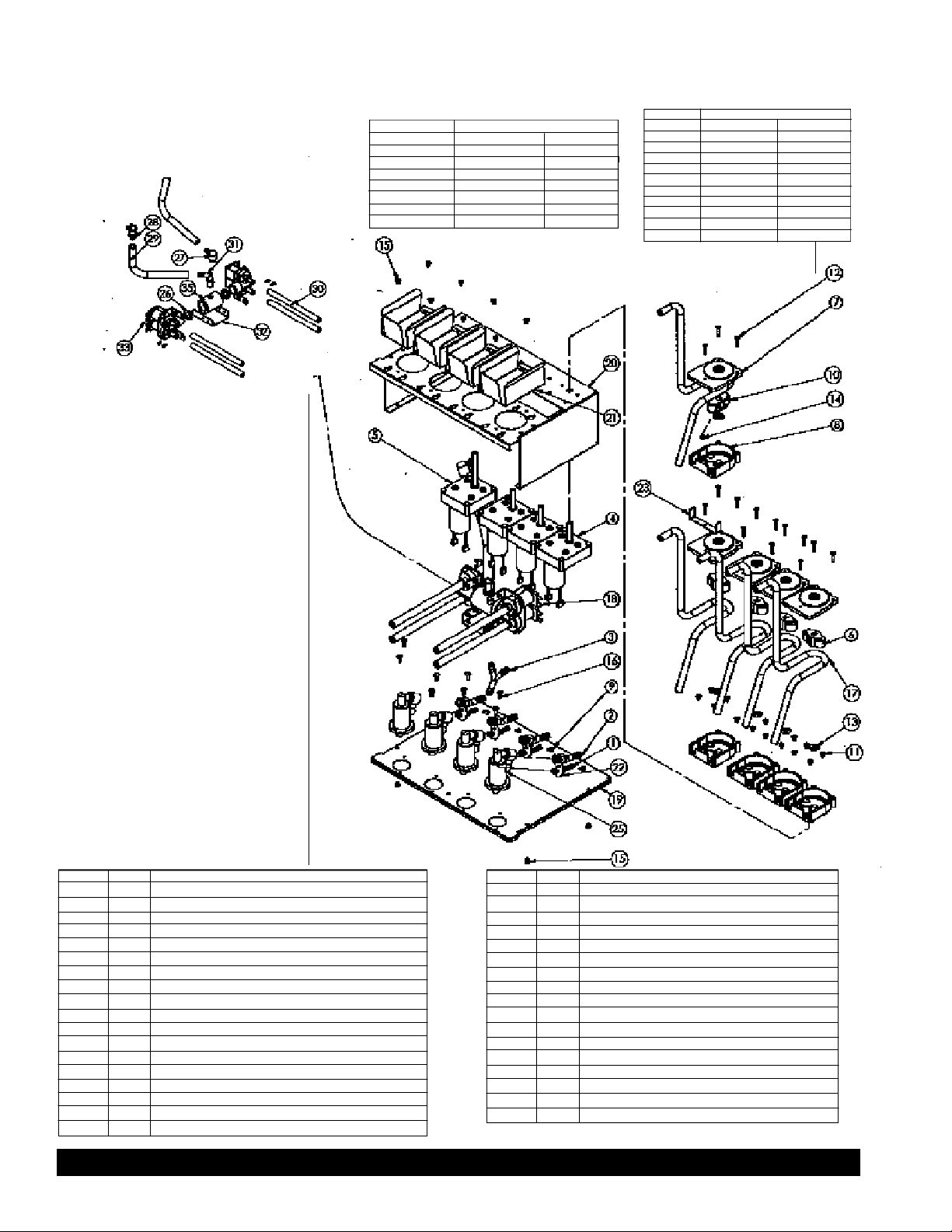
DISPENSING BASE EXPLODED VIEW
REPLACEMENT PUMP KITS MAY BE ORDERED AS FOLLOWS:
P/N 9400 KIT PERSTALTIC PUMP SINGLE
ITEM P/N QTY
6 9134 1
7 9135 1
8 9136 1
11 9160 4
12 9161 3
13 9162 1
17 9177 1
P/N 9401 KIT PERSTALTIC PUMP DUAL
ITEM P/N QTY
6 9134 1
7 9135 2
8 9136 2
10 9141 1
11 9160 4
12 9161 6
13 9162 2
14 9163 1
17 9177 2
23 9334 1
ITEM P/N DESCRIPTION
1 9103 FITTING, ELBOW 45 1/4 X BARB
2 9123 FITTING, ELBOW 45 3/8 X BARB DOUBLE O’ RING
3 9124 FITTING, Y BARB X 1/4 ID
4 9132 GEAR MOTOR, SHORT SHAFT 24V DC NOM
5 9133 GEAR MOTOR, LONG SHAFT 24V DC NOM
6 9134 ROLLER ASSY, SYRUP, PERISTALTIC PUMP
7 9135 COVER, ANKO PERIST, PUMP 810
8 9136 HOUSING, ANKO PERIST, PUMP 810 REAR
9 9137 SCREW, 8-32 X 3/8 TAPTITE II SS BLACK
10 9141 ROLLER ASSY, JUICE TOP PUMP, PERISTALTIC
11 9160 SCREW, 8-32 X 5/16 PH PN HD SS
12 9161 SCREW, 6-32 X 3/4 SS PH PH
13 9162 WASHER, SPACER, PUMP HOUSING
14 9163 SET SCREW, ANKO PUM PROLLER
15 9164 SCREW, 8-32 X 1/4 PH PN HD 18-8 SS
16 0069 SCREW, 8-32 X 1/2 PH TR HD TY PE F 410 SS
17 9177 TUBING NORPRENE, 810 ANKO PERISTALTIC PUMPS
18 9212 DUAL VALVE ASSEMBLY
ITEM P/N DESCRIPTION
19 9312 BASE, DISPENSING
20 9314 SHELF, DISPENSING
21 9324 BRACKET, TETRA PACK HOLDER
22 9330 BRACKET, FITTINGS HOLDER
23 9334 BRACKET, PERIST PUMP RETAINER
24 9513 HARNESS, DISPENSING PLATFORM (NOT SHOWN)
25 9816 CHAMBER, MIXING
26 9104 GASKET, MANIFOLD
27 9118 FITTING, 3/8" ID CPC ELBOW W/SHUTOFF
28 9119 FITTING, 3/8" ID CPC STRAIGHT
29 9153 TUBING, 3/8" ID INNERBRAIDED PV C
30 9143 TUBE, 1/4 X 1/8 WALL TY GON (B-44-4X)
31 9190 FITTING, 1/4 NPT X 3/8 BARB ELBOW
32 9328 BRACKET, DUAL WATER VALVE
33 9502 VALVE DUAL OUTLET, 1.0 GPM 24V DC COIL
34 9511 HARNESS, DAISY JUMPER (NOT SHOWN)
35 9806 MANIFOLD, DUAL VALVE
Crathco® Post Mix Beverage Page 19
Page 20

REFRIGERATION SYSTEM EXPLODED VIEW
ITEM P/N DESCRIPTION
1 9137 SCREW, 8-32 X 3/8 TAPTITE II SS BLACK
2 9109 TUBING, 3/8 D X 1/16 WALL TY GON B-44-4X
3 9153 TUBING, 3/8 D INNERBRAIDED PVC
4 9201 CONDENSING UNIT ASSEMBLY 220V
9227 CONDENSING UNIT ASSEMBLY 115V
5 9202 ICE-BANK ASSEMBLY 220V
9228 ICE-BANK ASSEMBLY 115V
6 9703 ACCUMULATOR, 1 3/16 OD X 8"
Page 20 Crathco® Post Mix Beverage Dispensers
Page 21
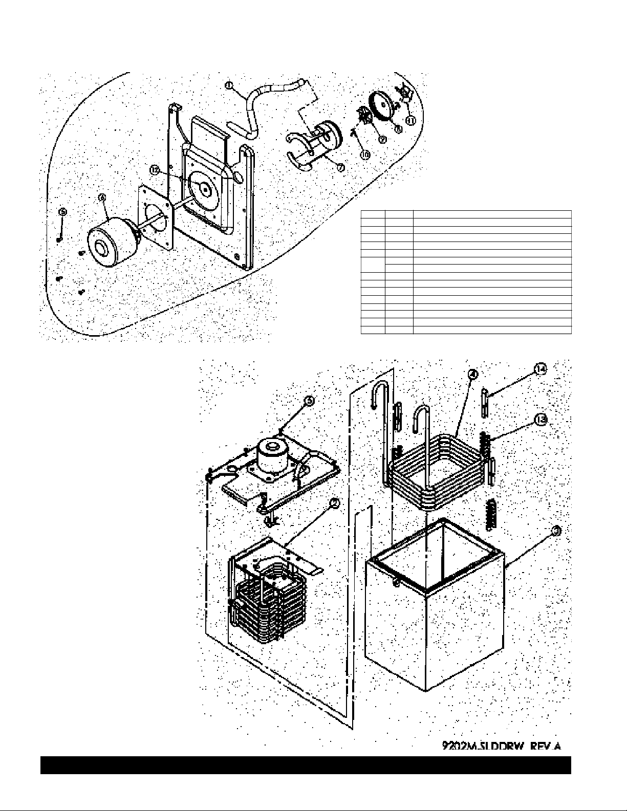
EVAPORATOR ASSEMBLY/CABINET COOLING PUMP EXPLODED VIEW
ITEM P/N DESCRIPTION
1 9413 TUBING, 3/8 D X 1/16 WALL TYGON
2 9203 EVAPORATOR ASSEMBLY, ICE-BANK
3 9225 TANK FOAMED, ICE-BANK
4 9701 COIL, WATER COOLING HEAT EXCHANGER
5 9411 SCREW, 8-32 X 3/8 TAPTITE II SS BLACK
6 9500 MOTOR AGITATOR 220V 50Hz
9531 MOTOR AGITATOR 115V/60Hz
7 9818 HOUSING, WATER PUMP
8 9819 CLOSURE, WATER PUMP
9 9817 IMPELLER
10 9127 P/N COTTER, .062 DA X 1"
11 9131 PROPELLOR
12 9404 WASHER, 1.25 OD X .310 ID X .120 THK NYLON
13 9318 BRKT, SPACER WATER LINE
14 9327 STRIP, COIL RETAINING
Crathco® Post Mix Beverage Page 21
Page 22

UPPER CABINET EXPLODED VIEW
ITEM P/N DESCRIPTION
1 9505 FAN, COOLING 20-27 VDC
2 9718 COIL, CABINET COOLING
3 9813 SHROUD, CABINET COOLING
4 9137 SCREW, 8-32 X 3/8 TAPTITE II SS BLACK
5 9519 HARNESS, COOLING FAN EXTENSION
6 9138 SCREW, #8 X 1 1/2 PH PN HD ZINC PL
7 9109 TUBING, 3/8 ID X 1/16 WALL TYGON
8 9140 SCREW, 8-32 X 1/2 PH TR HD TY PE F 410 SS
9 9217 CABINET COOLING SYSTEM
10 9313 BRACKET, RETAINER
11 9815 BUSHING
12 9411 SCREW, #8 X 1/2 HEX HD SELF DRILL
Page 22 Crathco® Post Mix Beverage Dispensers
Page 23

MERCHANDISER EXPLODED VIEW
ITEM P/N DESCRIPTION ITEM P/N DESCRIPTION
1 9128 BEARING, HINGE 9 9528 STARTER
2 9167 KEYED DOOR LOCK 10 9529 HARNESS, LIGHT KIT (NOT SHOWN)
3 9173 FEATHER FASTNER-FASTEX, TRUSSHEAD 11 9800 GASKET DOOR, PVC
4 9323 PANEL, GASKET RETAINING 12 9807 MERCHANDISER, DOOR
5 9511 HARNESS, DAISY JUMPER (NOT SHOWN) 13 9809 COVER PLEXI, GRAPHIC
6 9524 LAMP, F8T5 FLUORESCENT 14 9821 GRAPHIC
7 9525 HOLDER, MINI-BI PIN 15 9411 SCREW, #8 X 1/2 HEX HD SELF DRILL ZINC
8 9527 SWITCH, DISPENSING
ACCESSORY KIT EXPLODED VIEW
ITEM P/N DESCRIPTION
16 9170 MANUAL (NOT SHOWN) FRENCH
9408 MANUAL (NOT SHOWN) ENGLISH
17 9211 PICK UP TUBE ASSEMBLY, SYRUP
18 9812 HOLDER, DUAL PICK UP TUBE
19 9106 PICK UP TUBE CONCENTRATE
20 9326 BRACKET, PICK-UP TUBE
21 0069 SCREW, 8-32 X 1/2 PH TR HD TYPE F 410 SS
22 9216 PICK UP TUBE ASSEMBLY, JUICE
23 9325 GRILL, DRIP PAN
24 9192 LEG, 2 1/2" CHROME
25 9808 DRIP TRAY
Crathco® Post Mix Beverage Page 23
Page 24

Page 24 Crathco® Post Mix Beverage Dispensers
Page 25
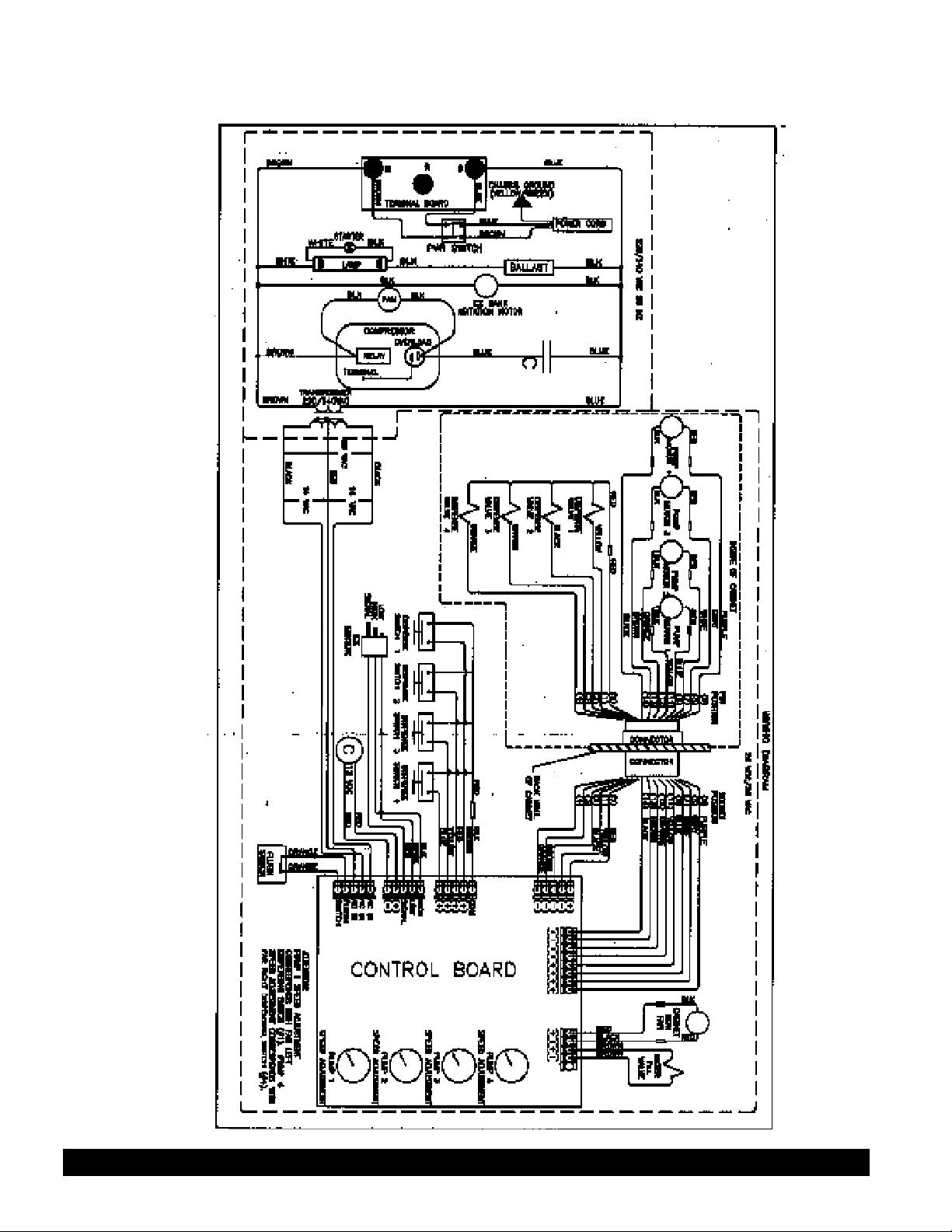
Crathco® Post Mix Beverage Page 25
Page 26
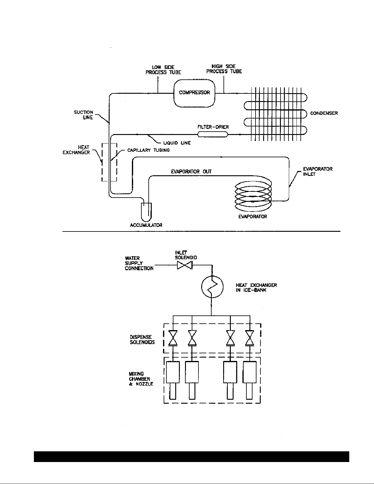
REFRIGERATION DIAGRAM
PLUMBING DIAGRAM
Page 26 Crathco® Post Mix Beverage Dispensers
 Loading...