

Page 1
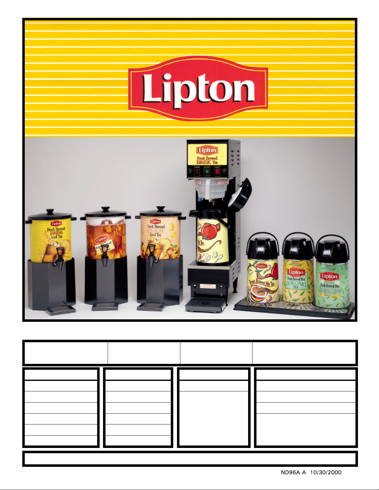
LIPTON TEA BREWING EQUIPMENT
Iced Tea
Dispensers
MANUAL
Hot Tea
Dispensers
• SPECIFICATIONS
• INSTALLATION
MACHINE MODELS
LTB-303 or PORTABLE
LTB-505 or PORTABLE
LTB-103 or PORTABLE
LTB-105 or PORTABLE
LTB-1010
LTB-1010 TWIN
For Equipment Repair & Service Please Call 1-800-737-5064
• OPERATIONAL
INSTRUCTIONS
ICED TEA DISPENSERS HOT TEA DISPENSER
LB1-3 gal.
LB1-5 gal.
LRB-3 gal.
LRB-5 gal.
SU-10P [10 gal.]
• ADJUSTMENTS
• COMPONENTS
3 Lt. AIRPOT V226A
• PARTS IDENTIFICATION
• WIRING DIAGRAMS
PLASTIC TRAYS and S.S. GRILLS
SINGLE M634A and RV29A
DOUBLE M633A and RV30A
TRIPLE M618A and RV31A
Page 2
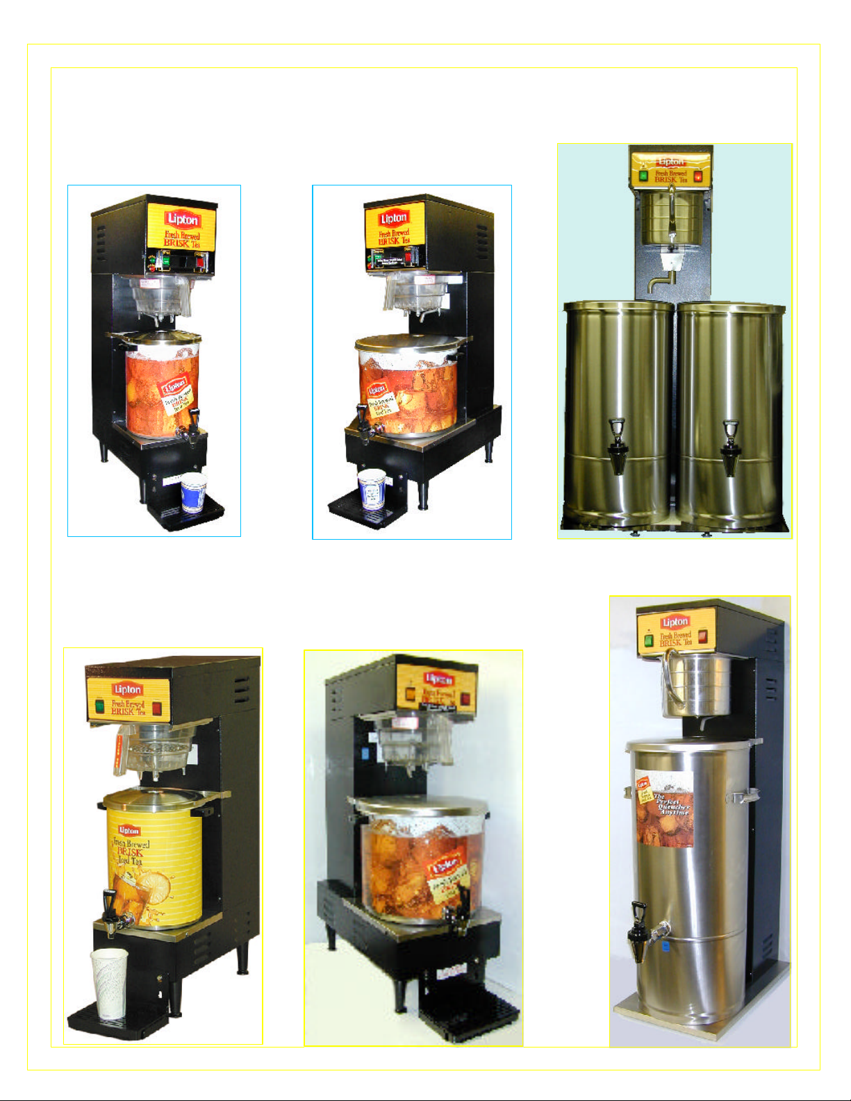
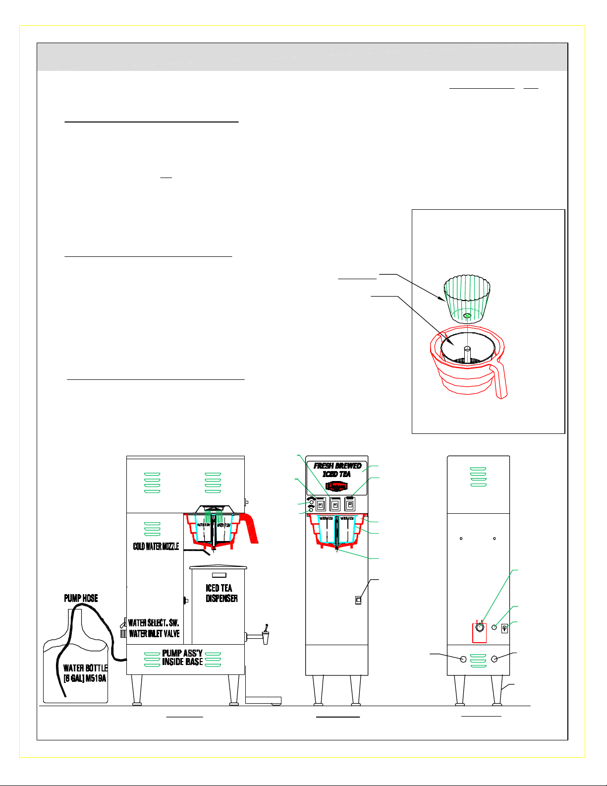
LTB-303 W/ LIT STEEPING FUNNEL
[HOT WATER SPOUT - OPTIONAL]
LTB MODELS:
LTB-1010 TWIN
WITH PLATFORM FUNNEL
LTB-505.
W/ LIT STEEPING FUNNEL
LTB-103.
W/ PLATFORM FUNNEL
LTB-1010 W/PLATFORM FUNNEL
LTB-105.
W/ PLATFORM FUNNEL
2
Page 3
ELECTRICAL SPECIFICATIONS
MODEL NO.
LTB-303C, 505-IT, LTB-103, 105
VOLTS
120
PHASE
1
HZ
60
WATTS
KW
1.8
NO. OF
HEATERS
1
AMPS
15
RECEPTACLE
NEMA NO.
5-15R
POWER
CORD
5-15P [2 WIRES+GND]
* LTB-PORTABLE - OPTIONAL
LTB-303, 505, LTB-103, 105
LTB-1010, LTB-1010 DUAL
OPERATING ENVIRONMENTAL TEMPERATURE:
Mininum Ambient Temperature: 32º F [0º C]
NOTE: The appliance is not suitable for unsupervised use by young children or aged or infirm persons,
according to national standards.
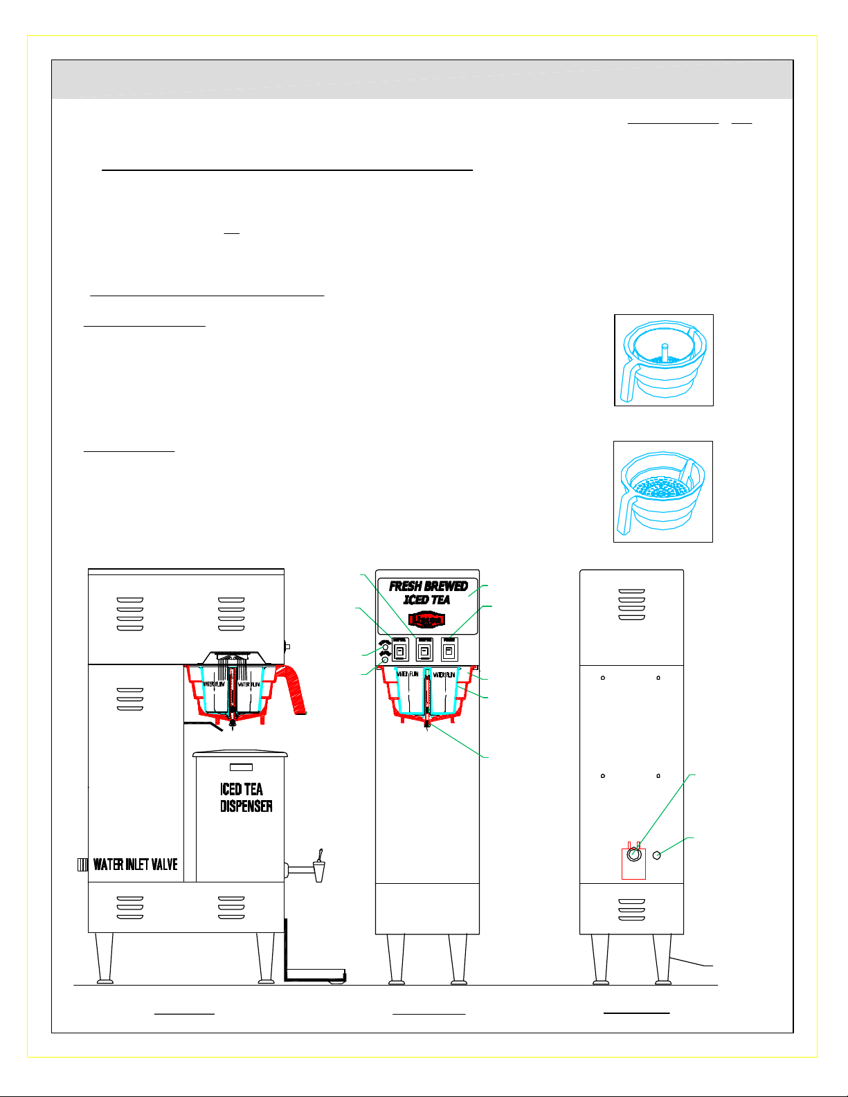
UNPACKING AND ASSEMBLY:
The LTB- 303, 505, 103, 105 is shipped with a set of short adjustable legs mounted on and an
additional set of 4" legs with drip tray, funnel, and a water inlet fitting. Install 4" legs to use drip tray.
The LTB-1010 and LTB-1010 Twin is shipped with a set of short adjustable legs mounted on, a
funnel, and a water inlet fitting.
WATER INLET CONNECTION:
HIGHLY RECOMMENDED: A water shut-off valve and a water filter, preferably a combination charcoal/
phosphate filter, to remove odors and inhibit lime and scale build up in the machine.
Note: In areas with extremely hard water, a water softener must be installed in order to prevent a
malfunctioning of the equipment and in order not to void the warranty.
The tea dispenser is equipped with a ¼" flare water inlet fitting which is located in the back of the unit.
Connect the ¼" dia. Copper waterline to the ¼" flare water inlet fitting of the valve.
240
240
1
60
3.0
1
60
4.8
1
12.5
2
20
6-20R
6-30R
6-20P [2 WIRES+GND]
6-30P [2WIRES+GND]
CIRCUIT
BREAKER AMPS
15A
20A
30A
This equipment is to be installed to comply with the applicable federal, state, or local plumbing codes
having jurisdiction. In addition:
1. A quick disconnect water connection or enough extra coiled tubing (at least 2x the depth of the
unit) so that the machine can be moved for cleaning underneath.
2. An approved back flow prevention device, such as a double check valve to be installed between
the machine and the water supply.
3. For use of machine outside the United States of America, connection to water supply mains
should comply with the national "Model Water Byelaws"
NOTES:
1. The machine is equipped with a low temperature lockout system and will not brew until the hot
water tank is filled with water and has reached the proper brew temperature of 195°f. To test
machine with cold water, leave heater switch off.
2. For Portable [-P] units: As the machine brews and dispenses tea, the pump will automatically draw
water from the water bottle to maintain tank full. Be sure to keep a second full bottle of water next to
the machine, so that when one bottle runs out of water you can transfer the hose to the next bottle.
3. For Portable [-P] units: The pump needs to be reprimed whenever the pump priming button lights up:
a) If the bottle runs out of water.
b) If the hose inside the bottle is pulled out of the water while the pump is drawing water, causing airlock.
4. For Portable [-P] units: From time to time after the tank is full, and machine has not been used for
some time, the priming button will light up, indicating that the pump is airlocked, due to pressure build
up. When the brew button is pressed, it releases the trapped air between the pump and the dispense
valve, and normal operation will resume.
After the tank is full the pump will stop drawing water, it will not start drawing water again until the
brew button is pressed causing the dispense valve to open up and dispense water.
3
Page 4
FAST START UP INSTRUCTIONS FOR LTB-303, 505, 103, 105
CAUTION: BEFORE PLUGGING POWER CORD INTO GROUNDED OUTLET [15A, 120V 0r 240V] MAKE SURE HEATER SWITCH IS OFF
[Heater Switch is located inside Top Housing. Remove Top Cover for Access].
I. PRIMING - FIRST TIME START UP - CONNECTED TO DIRECT WATERLINE
1. CONNECT A 1/4 Inch COPPER WATER LINE TO THE 1/4 FLARE WATER INLET FITTING ON THE VALVE.
2. PLUG POWER CORD INTO DEDICATED OUTLET [120V, 15A, GROUNDED.]
3. PRESS POWER SWITCH ON. Tank will start filling.
4. WAIT APPROX. 4 MIN. FOR TANK TO FILL UP.
5. TURN HEATER SWITCH ON [Heater Switch is located inside Top Housing. Remove Top Cover for Access].
II. NORMAL EVERYDAY BREWING OPERATION:
For LTB-303 & LTB-505:
1. Insert Paper filter with hole over stem and place tea IN PAPER FILTER - OPTIONAL
OR PLACE TEA DIRECTLY IN FUNNEL INSERT.
[for 3 gal. (1) 3 oz. bag or 2.5 - 3 oz. loose tea] [for 5 gal. (1) 4 oz. bag or 3.5 - 4 oz. loose tea]
2. Place iced tea dispenser or airpot under funnel.
3. Press Power Switch ON. Allow approx. 20 minutes for water in tank to reach brewing temperature 197°F.
4. When "Ready Light" [green] comes ON, press Brew Button [HOT TEA or ICED TEA].
For LTB-103, 105:
1. PLACE TEA BAG (3 OZ.) DIRECTLY INTO FUNNEL.
2. Place iced tea dispenser or airpot under funnel.
3. Press Power Switch ON. Allow approx. 20 minutes for water in tank to reach brewing temperature 197°F.
4. When "Ready Light" [green] comes ON, press Brew Button [HOT TEA or ICED TEA].
LTB-303
[2.5 - 3 OZ. TEA]
LTB-505
[3.5 - 4 OZ. TEA]
LTB-103
[2.5 - 3 OZ.TEA]
LTB-105
[3.5 - 4 OZ.TEA]
Z:\DRAWINGS\ND000\ND96A-A-LTB-MAN.dwg, 03/21/2002 04:34:40 PM, 1:8.01226
ICED TEA
BREW SW.
HOT TEA
BREW SW.
HEATER LT.
READY LT.
LABEL
POWER
SWITCH
FUNNEL
BREW
BASKET
SIPHONING
TUBE
WATER INLET
VALVE-HAND
TIGHTEN
POWER
CORD
LEGS
SIDE VIEW FRONT VIEW
4
BACK VIEW
Page 5
FAST START UP INSTRUCTIONS FOR LTB PORTABLE (Lipton Portable Tea Brewer with Pump)
CAUTION: BEFORE PLUGGING POWER CORD INTO GROUNDED OUTLET [15A, 120V 0r 240V] MAKE SURE HEATER SWITCH IS OFF
[inside top cabin].
I PRIMING - FIRST TIME START UP USING PUMP
1. SET WATER SELECTION SWITCH [see lower back panel] TO "PUMP" [TOGGLE UP]
2. PLACE HOSE FROM PUMP [on back panel] INTO A 6 GAL. FULL WATER BOTTLE.
3. PLUG POWER CORD INTO OUTLET [120V, 15A, GROUNDED, DEDICATED].
4. PRESS POWER SWITCH ON. Pump priming button [red], located on lower front panel, will light up, indicating pump needs to be primed.
5. PUSH and HOLD PRIMING BUTTON UNTIL LIGHT GOES OFF, THEN RELEASE BUTTON. Pump begins to draw water from water bottle.
Pump will continue to draw water from the bottle on it's own, until the tank inside the machine is full.
Pump will take approximately 4 minutes to fill Tank.
6. TURN HEATER SWITCH ON [on lower back panel] .
Allow approx. 20 minutes for water inside tank to reach proper brewing temperature of 197°F.
II. NORMAL EVERYDAY BREWING OPERATION:
1. Insert Paper Filter with hole over stem and place Tea IN PAPER FILTER - OPTIONAL
or PLACE TEA [FOR LTB-303 [(1) 3 oz. bag or 2.5 - 3 oz. loose tea] or
[FOR LTB-505 [(1) 4 oz. bag or 3.5 - 4 oz. loose tea] DIRECTLY IN FUNNEL INSERT.
2. Place iced tea dispenser or airpot or satellite under funnel.
3. Turn power on. Allow approx. 20 minutes for water in tank to reach brewing temperature 195°F.
4. When "Ready" [green] light [front panel] comes ON, press Brew Button [HOT TEA or ICED TEA].
5. IF IN BETWEEN BREW CYCLES, THE PRIMING BUTTON LIGHTS UP, PRESS BREW SWITCH,
TO CONTINUE WITH NORMAL OPERATION.
BEFORE BREWING, SLIP LIPTON PAPER FILTER
FILTER WITH HOLE [412 LIP] OVER STEM and
EMPTY 3 OZ. OF TEA INTO PAPER FILTER.
FILTER IS OPTIONAL
USED WHERE RINSING
FUNNEL IS LIMITED
III. AFTER DEMONSTRATION- PACK UP MACHINE:
1. SHUT OFF ALL SWITCHES
2. UNPLUG POWER CORD
3. DRAIN TANK INTO WATER BOTTLE [Drain Hose located in back]
CAUTION: WATER IN TANK IS HOT, 197°F.
Z:\DRAWINGS\ND000\ND96A-A-LTB-MAN.dwg, 03/21/2002 04:34:58 PM, 1:8.01226
ICED TEA
BREW SW.
HOT TEA
BREW SW.
HEATER LT.
READY LT.
LABEL
POWER
SWITCH
FUNNEL
BREW BASKET
SIPHONING TUBE
PUMP PRIMING
BUTTON
DRAIN
HOSE
LTB-303 [2.5 - 3 OZ. TEA]
LTB-505 [3.5 - 4 OZ. TEA]
WATER INLET
VALVE-HAND
TIGHTEN
POWER CORD
pump
WATER
SELECTION
water line
BUTTON
PUMP HOSE TO
WATER BOTTLE
LEGS
SIDE VIEW FRONT VIEW
5
BACK VIEW
Page 6
FAST START UP PROCEDURE FOR LTB -1010 & LTB-1010 TWIN
CAUTION: BEFORE PLUGGING POWER CORD INTO GROUNDED OUTLET [15A, 120V 0r 240V] MAKE SURE HEATER SWITCH IS OFF [on
back panel or inside top cabin].
I. PRIMING - FIRST TIME START UP CONNECTED TO DIRECT WATERLINE
1. CONNECT A 1/4 COPPER WATER LINE TO THE 1/4 FLARE WATER INLET FITTING ON THE VALVE.
2. PLUG POWER CORD INTO OUTLET [120V, 15A, GROUNDED, DEDICATED].
3. PRESS POWER SWITCH ON. Tank will start filling.
4. WAIT APPROXIMATELY 4 MIN. FOR TANK TO FILL UP, THEN TURN HEATER SWITCH ON [ Toggle UP - see lower back panel]
LTB-1010
II. NORMAL EVERYDAY BREWING OPERATION:
For LTB-1010:
1. PLACE TEA BAGS [2] 4 oz. each, 8 oz. total, DIRECTLY ONTO FUNNEL PLATFORM.
2. Place Iced Tea Dispenser under funnel.
3. Turn power on. Allow approx. 15 minutes for water in tank to reach brewing temperature 197°F.
4. When "BREW" [green] light comes ON, press Brew Button [toggle down].
BREW/CAUTION LIGHT flashes during brewing cycle. DO NOT REMOVE FUNNEL WHILE LIGHT IS FLASHING.
BREW
CAUTION
LIGHT
ICED TEA
BREW SW.
LABEL
POWER
SWITCH
[8 OZ. TEA]
10 gal.
ICED TEA
DISPENSER
Z:\DRAWINGS\ND000\ND96A-A-LTB-MAN.dwg, 03/21/2002 04:35:12 PM, 1:8.07091
COLD WATER
NOZZLE
SIPHONINING
TUBE
FUNNEL
HEATER
SWITCH
OR
INSIDE TOP
HOUSING
POWER
CORD
DUAL
WATER
INLET/
SOLENOID
VALVE
SIDE VIEW
6
FRONT VIEW
BACK VIEW
Page 7
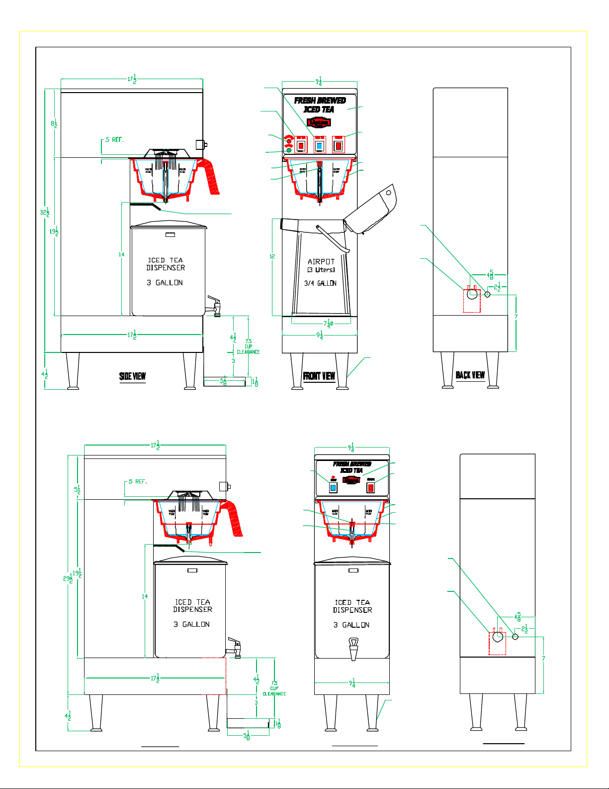
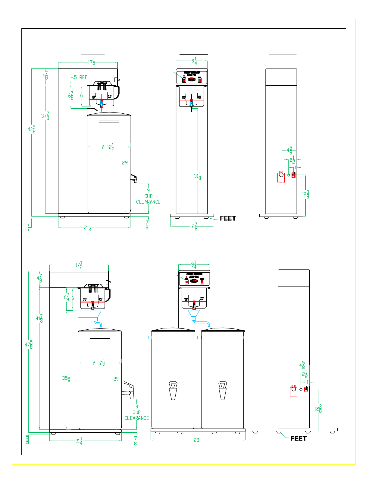
LTB-303 DIMENSIONAL SPECIFICATIONS
ICED TEA
BREW SW.
HOT TEA
BREW SW.
HEATER LT.
READY LT.
END CAP/NUT
SIPHONING
TUBE
COLD
WATER
NOZZLE
LABEL
POWER
SWITCH
FUNNEL
BREW BASKET
WATER INLET
VALVE-HAND
TIGHTEN
POWER
CORD
LEGS
LTB-103 DIMENSIONAL SPECIFICATIONS
ICED TEA BREW
SW. WITH
READY LT.
END CAP/NUT
SIPHONING
TUBE
COLD WATER
NOZZLE
LABEL
POWER
SWITCH
FUNNEL
BREW BASKET
BREW PLATFORM
POWER
CORD
WATER INLET
VALVE-HAND
TIGHTEN
SIDE VIEW
LEGS
FRONT VIEW
7
BACK VIEW
Page 8
LTB-505 DIMENSIONAL SPECIFICATIONS
ICED TEA
BREW SW.
HEATER LT
READY LT
END CAP/NUT
SIPHONING
TUBE
COLD
WATER
NOZZLE
LABEL
POWER
SWITCH
FUNNEL
BREW BASKET
BREW PLATFORM
POWER
CORD
WATER INLET
VALVE-HAND
TIGHTEN
SIDE VIEW
FRONT VIEW
LTB-105 DIMENSIONAL SPECIFICATIONS
ICED TEA BREW
SW. WITH
READY LT.
END CAP/NUT
SIPHONING
TUBE
COLD
WATER
NOZZLE
LEGS
BACK VIEW
LABEL
POWER
SWITCH
FUNNEL
BREW BASKET
BREW PLATFORM
POWER
CORD
WATER INLET
VALVE-HAND
TIGHTEN
SIDE VIEW
LEGS
FRONT VIEW
8
BACK VIEW
Page 9
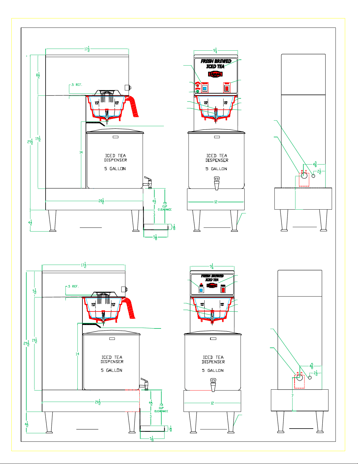
LTB-1010 DIMENSIONAL SPECIFICATIONS
SIDE VIEW
ICED TEA
DISPENSER
FRONT VIEW BACK VIEW
ICED TEA BREW
SW. WITH
READY LT
10 gal.
LTB-1010 TWIN DIMENSIONAL SPECIFICATIONS
ICED TEA BREW
SW. WITH
READY LT
10 gal.
ICED TEA
DISPENSER
10 gal.
ICED TEA
DISPENSER
10 gal.
ICED TEA
DISPENSER
9
Page 10
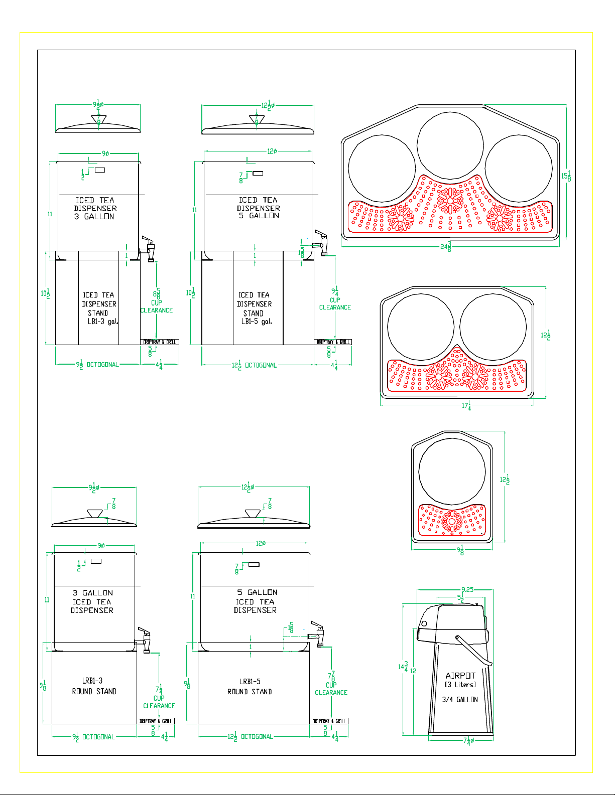
ACCESSORIES - DIMENSIONAL SPECIFICATIONS
LB1-3 LB1-5
HTT3
HTT2
LRB-1-3 LRB1-5
HTT1
3 LITER AIRPOT
10
Page 11

TEA BREWING RECOMMENDED MEASUREMENTS
GROUND TEA
MODEL #
LTB-303, LTB-103
LTB 505, LTB-105
LTB-1010
Allow approximately 10 minutes for a complete brew cycle.
DO NOT remove brew funnel until it has stopped dripping.
Serve Fresh Brewed Tea from dispensing faucet into tea
glass over ice.
LOOSE or BAGGED
2.5 - 3 oz. (1) 3 oz. bag
3.5 - 4 oz. (1) 4 oz. bag
8 oz. (2) 4 oz. bag
TEA BAGS - Place correct number of tea bag(s) directly
into brew funnel.
Replace funnel into brew head of unit and push brew switch,
when GREEN READY LIGHT comes on.
GROUND TEA LEAVES - Place paper filter into brew
funnel and add proper amount of fresh ground tea leaves
into filter. Replace funnel into brew head of unit and push
brew switch when GREEN READY LIGHT comes on. See
chart above for the recommended ounces of ground tea
leaves.
LTB-303
LTB-505
LTB-103
LTB-105
11
LTB-1010
Page 12
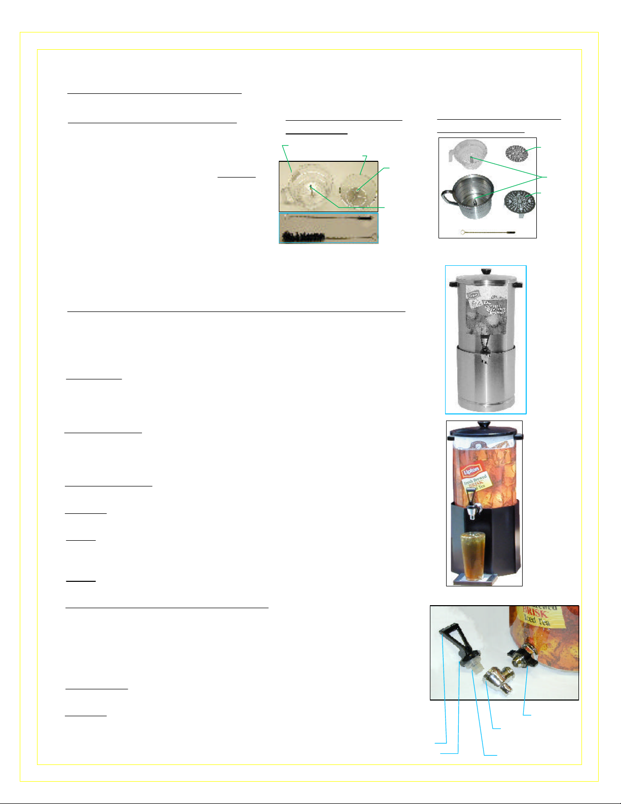
SANITIZING AND CLEANING INSTRUCTIONS FOR LIPTON TEA BREWING EQUIPMENT
I. DAILY CLEANING OF MACHINE - Wipe clean all surfaces of the machine.
II. DAILY CLEANING OF FUNNELS
STEEPING BREW FUNNEL
LTB-303, 505
1. Clean and rinse brew funnel
between brewing cycles.
2. Wash steeping brew funnel weekly
with soap and warm water,
STEEPING BREW FUNNEL WITH
STEEPING BREW INSERT
SYPHONING
TUBE
rinse thoroughly with fresh water.
3. Remove brew basket from steeping
funnel by spinning it off (ccw) or
pull out platform from platform funnel.
VALVE
VALVE BRUSH
SYPHON BRUSH
4. Use small/valve brush to clean brew
funnel valve. Use larger/syphon
brush to clean syphoning tube.
III. DAILY CLEANING OF STAINLESS STEEL ICE TEA DISPENSERS
Proper cleaning and sanitizing of the faucet on your tea dispenser
s necessary to deliver great tasting fresh brewed iced tea.
Tomlinson SPB faucets do not require tools for cleaning and sanitizing.
Important: To prevent bacterial growth and protect tea flavor,
clean and sanitize tea brewing and dispensing equipment at least once
a day as follows:
PLATFORM BREW FUNNEL
LTB-103, 105, 1010
PLATFORM
LTB-103, 105
VALVE
PLATFORM
LTB 1010
VALVE BRUSH
LRB
Dispenser
1) Inside surface: Using hot water (140°F) and dishwashing detergent,
scrub interior of dispenser and covers with non abrasive bristle brush,
including corners and bottom. Be sure the interior of the outlet shank
is scrubbed out to remove residues, then rinse thoroughly.
2) Outside surface: Wash surface with sponge using hot water and
dishwashing detergent.
3) Sanitize all interior surfaces of the dispenser, including any
mixing utensils and covers, with a chlorine solution (50 ppm).
Note: A chlorine solution is easily prepared by putting two
capfuls of chlorine into one gallon of warm water.
4) Sponge all outside surfaces with chlorine solution (50 ppm).
Note: Commercial dishwasher is acceptable.
IV. CLEANING AND SANITIZING FAUCET
1) Remove Faucet assembly from dispenser by loosening wing nut.
2) Dis-assemble faucet by unscrewing the bonnet. Pull seat cup
from faucet stem, and inspect seat cup for wear or hardening,
replace if necessary.
4) Scrub clean all faucet parts with bristle brush, using hot water
(140°F) and dishwashing detergent to remove all tea residues.
5) Sanitize by soaking all parts for a minimum of 3 minutes in the
chlorine solution (50 ppm). Let all sanitized parts drain and dry
Re-assemble faucet and reattach to dispenser.
HAND TIGHTEN ONLY!
12
FAUCET HANDLE
BONNET
LB
Dispenser
TOMLINSON FAUCET
SHANK
TOMLINSON FAUCET
LOWER ASS'Y
SEAT CUP
Page 13
ADJUSTMENTS - TO BE PERFORMED BY QUALIFIED SERVICE PERSONNEL ONLY.
Caution:
Brewers should be unplugged from electrical outlets before any service is performed.
The water flow rate coming from the hot water tank is constant/fixed at 0.75 gal/min.
Increasing or decreasing the amount of hot water dispensed from tank can also be used to adjust the strength of
the tea.
The Longer water flows - More water - Weaker tea; Less water flows - Less water - Stronger tea.
The LTB-303, 505, 103, 105, 1010 Machine will complete a full cycle in approximately 5 TO 10 min.
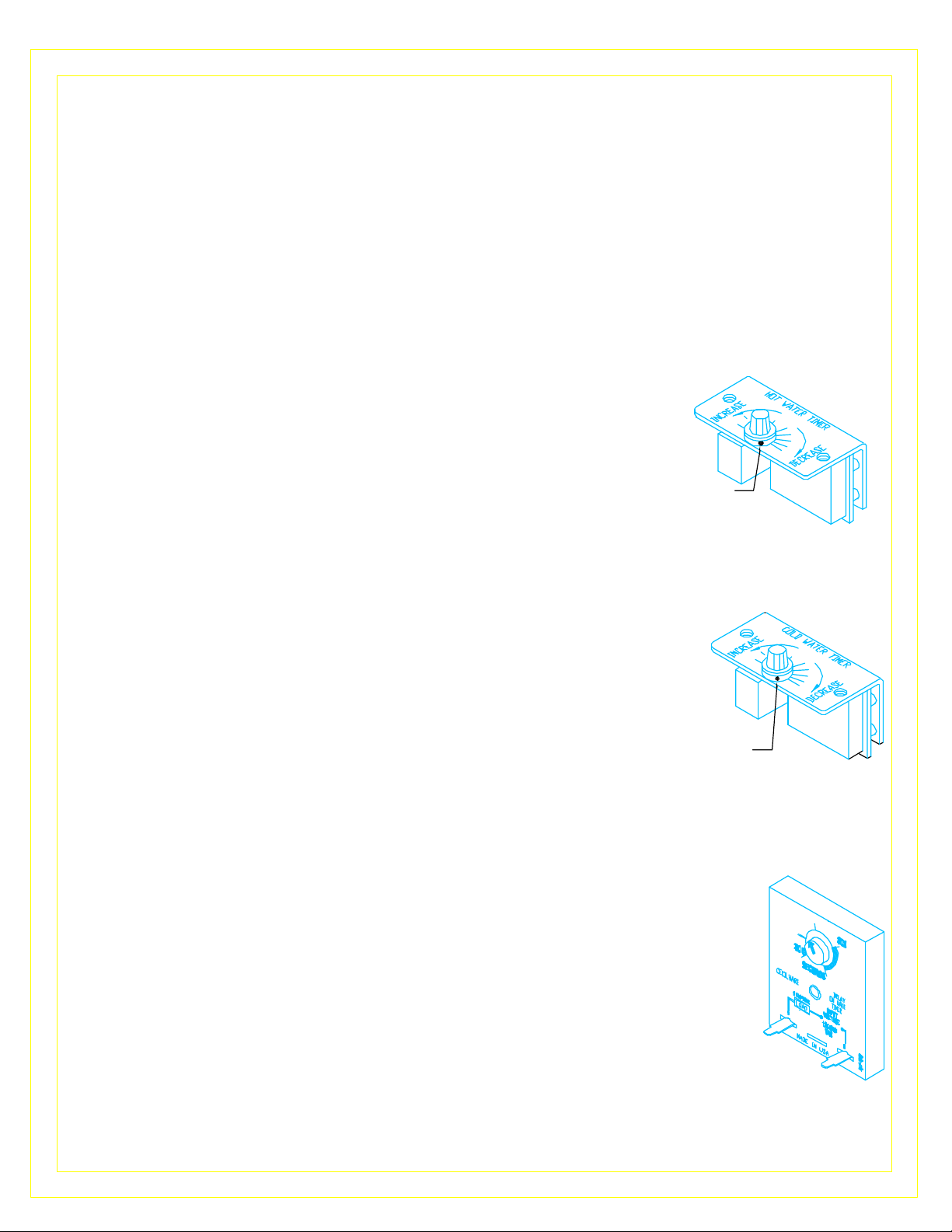
1. HOT WATER TIMER (BLACK L265A) ADJUSTMENT (MOUNTED ON TOP)
Controls the brewing time (min.) for brewing Coffee and Hot Tea Concentrate
Factory set at 3 min. for brewing 3 liters [3/4 gal.] of Tea Concentrate.
[later to be diluted with 2 1/4 gal. of cold water which makes up the
total 3 gal. Iced tea] .
To increase or decrease dispensing time and volume of hot
water dispensed, turn knob in the direction shown on timer.
Note: The brewing time, temperature, and amount of product used in the funnel
effects the drink strength. See chart of Tea Flavors and Grams to be used, supplied by Lipton.
2. COLD WATER TIMER (BLUE L264A) ADJUSTMENT (LTB-303, 505 ONLY)
(MOUNTED ON TOP).
Controls the dispensing time (min.) for cold water dilution of iced tea.
Factory set at 3 min. for dispensing 2 1/4 gal of cold water -
dispensed & mixed with 3 liters [3/4 gal.] of hot tea concentrate previously brewed .
To increase or decrease dispensing time and volume of Iced Tea dilution water
dispensed, turn knob in the direction shown on timer.
TO RESET TO FACTORY SETTINGS:
*Push the Brew Button (HOT TEA) , then adjust Timer to 3 or 5 min. [for 3 or 5 gal.] depending on the
water pressure in the main water line.
*Adjust the Dispense Valve 1/4 turn at a time, if necessary, to increase or decrease the Hot Water Flow.
*Push the Brew Button (ICED TEA) , then adjust the Timer to 3 min. or 5 min. [for 3 or 5 gal.] depending
on the water pressure in the main water line.
3. DELAY TIMER (L595A) [ALL LTB UNITS] -NEAR BASE, ABOVE WATER INLET VALVE.
(MOUNTED IN BACK)
Set Delay Timer knob approximately as shown in picture. This setting corresponds
to a delay time of 1.5 minutes after the hot tea begins to dispense.
If the water pressure requires a different setting on the Cold Water Timer,
then the Delay Timer also needs to be adjusted so that it delays the Cold Water
1.5 minutes after the hot tea begins to dispense.
APPROX. FACTORY SETTING:
LTB-303/103 3 MIN.
LTB-505/105 5 MIN.
APPROX. FACTORY SETTING:
LTB-303 3 MIN.
LTB-505 5 MIN.
If the water pressure is higher than 20 PSI , decrease the setting on the Cold Water Timer and Delay Timer.
If the water pressure is lower than 20 PSI , increase only the setting on the Cold Water Timer to Max.
13
Page 14

4. PROGRAMMABLE TIMER "TEACH ME" L576A ADJUSTMENTS - LTB-1010 :
This timer can be programmed from the brew button to dispense different volume of hot water.
PRIMING:
a. Make sure heater switch is off.
b. Push & hold down brew button while switching power on .
c. Release brew button.
d. Push brew button again & wait for water to start flowing out of spray head.
e. Switch power off .
Put timer into program mode:
a. Start with power off.
b. While holding down brew button, turn power on.
c. Release dispense button.
Program the brew button :
d. Push brew button to start time [product begins dispensing].
e. Push brew button again to stop time
[about 2" from top of dispenser for 10 gal.] [product stops dispensing] .
f. Brew button can be jogged to top off container.
Put timer into run mode:
g. Turn power off and on again [this locks in total dispense time].
Normal Operation: turn power on, turn heater switch on,
wait 20 minutes until ready light comes on. Unit is ready to brew.
5. DUAL WATER INLET VALVE CD241 [WAS L496A]:
The Water Inlet Valve is located on the lower part of the main body with
the threaded end protruding out of in the back.
The Water Inlet Valve allows water flow up to .87 gal./min. [gpm].
One side supplies water to the tank and one side supplies water directly
to the Iced Tea dilution water nozzle. The time that each side draws
water is controlled by the Hot Water timer and Cold Water Timer.
6. DISPENSE VALVE L467A :
Locate Dispense Valve, by removing the top lid of machine.
Looking down into the machine, the Dispense Valve is mounted on the tank.
FIXED FLOW: 1 LITER/MINUTE [0.26 gal./ minute]
LTB-303 3 liters in 3 minutes [0.78 gal. in 3 minutes]
LTB-505 5 liters in 5 minutes [1.3 gal. in 5 minutes]
LTB-1010 10 liters in 10 minutes [2.6 gal. in 10 minutes]
7. THERMOSTAT ADJUSTMENT L681A (WAS L002A or L626A):
Locate Thermostat: Remove the top cover. Thermostat is mounted on top of tank.
The thermostat is factory set to deliver hot brewing water at 195°F with the thermostat
knob turned to full ON position. If adjustments should be necessary to increase or
decrease the water TEMPERATURE, proceed as follows:
To INCREASE the water temperature,
Turn Thermostat Shaft to its maximum clockwise, CW, position.
Remove the knob and locate the Slotted Adjustment Screw inside
the hollow thermostat shaft. Using a narrow-bladed screwdriver,
engage slotted adjustment screw and turn it ¼ turn slowly counterclockwise, CCW .
Allow a few minutes for the temperature to reach set level. The Heater Light will go ON,
indicating the heating element is activated, wait for it to go OFF, indicating that the water
has reached new set temperature. Take a temperature reading and repeat if necessary.
To DECREASE the water temperature - simply turn the Thermostat Knob one notch
counterclockwise CCW to the next lower dial setting.
14
Page 15

CRITICAL COMPONENTS TESTS
A) Water Inlet Valve Test
Check hot water side, going to tank: Turn power off. If the water level
rises inside the tank, the Water Inlet Valve is leaking. Disconnect wires from
the Water Inlet Valve coil and connect a 2 wire line cord to the terminals.
Plug it into electrical outlet. If water flows in and stops when you pull it out,
the Valve is working fine. Repeat this test a few times. The problem may
be in the Probe or Water Level Control Board. If water does not flow in
when the cord is plugged into an electrical outlet, the Solenoid coil may be
damaged, opened, or the valve may have an obstruction preventing the
water from flowing in. Clean or replace it.
Check cold water side, going to dilution nozzle: Turn power off. If water
keeps coming out of the dilution nozzle, the solenoid might be clogged or
damaged.
A Check Valve should be provided and installed by the customer to prevent
backflow. To check proper function of Check Valve, disconnect water line
from the Check Valve, check for dripping from the disconnected end of the
Check Valve. If it leaks replace it.
B) Hi-Level Float Switch Test
The Float Switch acts as a guardian for the Solid State Level Control
Board and its Probe. If they malfunction and cause the water inside the tank
to rise, the Float Switch will prevent flooding by terminating the power to the
Solid State Control Board and the Water Inlet Valve. The correct mounting
position of the Float Switch in the tank is as shown in picture, with the
magnets in the Float Switch in the upper part of the switch.
BACKFLOW PREVENTION
CHECK VALVE
PROVIDED AND INSTALLED
BY CUSTOMER
FLOAT SWITCH
(70 V.A) L499A
After tank is full, unplug the wire to the Level Control Probe, the water
should run into the tank for a few more seconds until it reaches the Float
Switch and it should stop. If not, and water starts coming out of the
Breather tube, the Float Switch is malfunctioning.
C) Probe Test
If lack of water persists, check the probe as follows:
Turn on the power and water supply. Check inside the tank to make sure
the water is not touching the Probe. Pull wire and terminal out of the Probe
rod. If water still does not flow after the wire is disconnected from the
Probe, the problem may be in the Solid State Water Level Control Board. If
water starts flowing into the tank, the Probe may be grounded, due to
excessive liming. Check with Ohm meter. Clean or replace probe.
D) Solid State Water Level Control Board Test
Check the Board as follows:
1. Make sure there is power input to the Board at the terminals 2 & 3 Your
voltmeter should read 115 Volts. It should read the same at terminals 1 & 3.
This is the output power to electrify the coil of the Solenoid Valve to open it.
The lack of voltage at terminals 2 & 4 will indicate that the Board is not
working properly.
GROUNDING PLATE IN
2. Make sure all wire connections to the Board are tight.
3. The grounding plate at the top, in the back of the board should be
securely Grounded. The Board will not work or will work erratically,
if it is not grounded properly. If after this, the Board is still failing to
open the Water Inlet Valve, replace it.
BACK OF THE BOARD
GROUND
TERMINAL
TO PROBE
CORRECT
POSITION OF
MAGNETS
LEVEL CONTROL PROBE
K355Q [K402A & P410A]
TO
N
L1
SOLENOID
1
2
3
4
T5
L398C [120V]
L399C [240V]
SS WATER LEVEL CONTROL CCA
15
Page 16

TROUBLESHOOTING GUIDE
WARNING: To reduce the risk of electrical shock unplug the dispenser power cord before repairing or replacing any internal components of the
PROBLEM PROBABLE CAUSE REMEDY
1
Brewed Cold Tea.
2
Tea too weak.
3
Tea too strong.
4
Water keeps dripping
or running from
dilution nozzle.
a) Heater Switch OFF.
b) Run out of hot water
c) Thermostat is OFF.
d) Loose electrical connection.
e) Thermostat is defective.
f) Hi-Limit Temperature Switch is tripped.
g) Bad Heating Element or Heater is burned out.
h) Bad low temperature cutout circuit.
Contactor/Relay L538A
a) Not enough Tea in the funnel insert.
b) Water flow too low.
c) Brew time is too short.
d) Water is too cold.
a) Too much tea in the funnel.
b) Water flow is high
c) Brew time is too long.
d) Water is too hot.
a) Leaking Water Inlet Valve.
b) Clogged/stuck Water Dispense Valve
a) Turn Heater Switch ON.
b) Allow time for water in tank to heat after filling.
c) Set Thermostat at 197°F [to max. position].
d) Check all electrical connections for contact.
e) Replace Thermostat.
f) Reset the Hi-Limit button, If heater still does not work, replace
the Hi-limit Temperature Switch. See Item 6 of Tank Ass’y.
g) Replace Heater.
h) Replace Contactor/Relay. See item 2 of Description of Components.
a) Put more Tea in the funnel insert [see Lipton’s chart]
b) Check flow [should be .26 gal /min.] Replace Dispense Valve.
c) Adjust hot water timer to 3 min. max.
d) Adjust Thermostat to 197°F [to max. position]
a) Put less Tea in the funnel insert [see Lipton’s chart]
b) Check flow [should be .26 gal /min.] Replace Dispense Valve.
c) Adjust hot water timer to 3 min. 197°F [to max. position]
d) Adjust Thermostat to 197°F [to max. position]
a) Clean/check fittings of Water Inlet Valve.
Replace Water Inlet Valve if needed. See ”Water Inlet Valve Test”
b) Clean/unclog Water Dispense Valve.
Replace Dispense Valve if defective.
5
No water is going
into tank at all.
or
No water is coming
from dilution nozzle
6
Water will not stop
flowing into water
tank.
7
Water is not heating
up in the water tank.
a) Water Inlet Valve malfunction.
b) Hi-Level Float Switch malfunction.
c) Probe malfunction.
d) Solid State Water Level Controls board
malfunction.
e) Timer malfunction.
a) Water Level Probe malfunction.
b) Solenoid (Water Inlet Valve) malfunction.
c) Solid State Water Level Control board
malfunction.
d) Float Switch malfunction.
a) Heater Switch is OFF.
b) Thermostat is OFF.
c)Loose connection on Thermostat.
d) Hi-Limit Temperature Switch is tripped
or defetive.
e)Heater is burned out or defective.
h) Bad Low Temperature Cutout Circuit.
Contactor/Relay L538A.
a) Check Water Inlet Valve. Replace if necessary.
See “Water Inlet Valve Test”
b) Test High-Level Float Switch. See “High-Level Float Test”
c) Check Probe. Replace if necessary.
d) Check The Water Level Controls. Replace if necessary.
e) Check Timer: Time dispinsing time vs. set time on Timer.
Replace if necessary.
a) Check Level Control Probe. Replace if necessary. See “ProbeTest”.
b) Check Solenoid. Replace if necessary.
c) Check The Water Level Controls. Replace if necessary.
d) Replace Float Switch.
a) Turn Heater Switch ON.
b) Turn Thermostat ON. Turn Thermostat Knob Clockwise.
c) Make sure all wires and ring terminals on theThermostat are tight.
d) Reset the Hi-Limit Button, If heater still does notwork,
replace the Hi-limit Temperature Switch (see Item 6 in Tank ill.).
e) Replace the Heater.
h) Replace Contactor/Relay. See item 2 of Description of Components.
16
Page 17

Page 18

FUNNEL ASSEMBLIES
P/N DESCRIPTION
1 M494A SEAL PLUG GROMMET
2 RX60A TEA BAG SHELF
3 K612A SIPHONING TUBE-DRIP FREE
4 V239A BREW FUNNEL, CLEAR
POLYCARBONATE
5 N816A CAUTION LABEL
6 4100A "O" RING
7 P499A LOCK NUT
1
2
P/N DESCRIPTION
1 F412-LS PAPER FILTER W/HOLE- OPTIONAL
2 M615A BREW BACKET- MOLDED
3 H326Q SYPHONING TUBE S.S.-DRIP FREE
4 4100A "O" RING
5 V239A BREW FUNNEL, CLEAR POLY-
CARBONATE [WAS RED V212Q]
6 N816A CAUTION LABEL
7 P499A LOCK NUT
1
2
P/N DESCRIPTION
1 SC16A TEA BAG PLATFORM / PLATE
2 M494A SEAL PLUG GROMMET
3 K612A SYPHONING TUBE - DRIP FREE
4 Q196A BREW FUNNEL, S.S. - 1GAL.
5 N816A CAUTION LABEL
1
2
3
4
5
6
7
3
4
5
6
7
3
4
5
18
Page 19

1
48
2
3
4
5
6
7
8
9
10
8
11
12
13
14
15
47
46
45
44
43
42
41
40
39
38
37
16
17
18
19
20
21
22
23
24
25
36
35
34
33
32
31
26
27
28 29
30
19
Page 20

ITEM P/N
LTB-303
LTB-505
P/N
LTB-303
Portable
P/N
LTB-103
LTB-105
P/N
LTB-1010
PARTS DESCRIPTION (LIPTON TEA BREWER) QTY
1 L566A L566A L566A L566A WATER LEVEL CONTROL SENSOR (CCA) 1
2 L539A L539A L539A L539A
RELAY, DOUBLE POLE (120V) [LOW TEMP. LOCK OUT] [ L538A F/ 220V]
3 L265A L265A ——— L576A SINGLE-TIMER – F/Hot Water Dispensing time – BLACK [ L265E F/220V] 1
4 L069A L069A L069A L299A HEATER SWITCH (120V) 1
5 L264A
NF94A
L264A
NF94A
L264A
——–
——
——
SINGLE-TIMER – F/ Cold Water Dispensing time–BLUE [L263A F/ 220V]
LABELS FOR TIMERS – “COLD WATER” & “HOT WATER”
6 CH41A CH41A —— —— TRANSFORMER F/ FUNNEL LIGHT [LTB-303, 505, 2C3IC ONLY] 1
7 NC49A NC49A NH04A NH04A SWITCH PANEL LABEL 1
8 L636A L636A ——– —— BREW LIGHT FOR LIT FUNNEL 1
9 H360A H360A H360A H360A SPRAY HEAD TUBE ASS’Y 1
10 M197A M197A M197A —— RUBBER WASHER (FOR SPRAY HEAD) 1
11 C002A C165A C165A C260A HEATER PILOT LIGHT (RED) 1
12 C072A C072A C260A C072A READY PILOT LIGHT (GREEN) (SHORT) [120V & 220V] 1
13 SC34Q SC34Q SC34Q SC34Q SWITCH GUARD ASS’Y w/clear cover [SC34A+M713A+SCREW #304 SS 6-32x3/8] 1
14 L291A L291A L291A L291A BREW SWITCH (HOT TEA) (GREEN) [or L383A] [ use L292A for EXPORT ] 2
15 L565 L565A -------- ------- BREW SWITCH (ICED TEA) (AMBER 120V & 220V] 1
16 L155A L155A L155A L155A POWER SWITCH (RED) [120V & 220V] 1
17 D042A D042A D042A D042A FAUCET ASS’Y [ HOT WATER - OPTIONAL] 1
18 K107A K107A K107A H322Q NUT, SPRAY HEAD 1
19 E004A E004A E101A E101A SPRAY HEAD [WAS K219A] 1
20 H304Q H304Q H304Q H304Q U-TUBE ASS’Y, (cold water dispenser on front panel) 1
21 M615A M615A M615A SA27Q BASKET ASS’Y STEEPING or BREW-[W/SHELF] [FUNNEL INSERT] 1
22 V239A V239A V239A Q183A FUNNEL [3 and 5 gal. units ALTERNATE V212A RED W/ NF24A ON HANDLE ] 1
23 75015 75015 75015 —– GRILL – BLACK MOLDED PLASTIC 1
24 75060 75060 75060 —– DRIP TRAY PAN – BLACK MOLDED PLASTIC 1
25 RE73A RE73A RE73A —– DRIP TRAY BRACKET 1
26 M098A M098A M098A M098A BUMPER – BLACK 2
27 NA52A NA52A NA52A NA52A LABEL “ CAUTION HOT LIQUID” 1
28 P488A P488A P488A —– STUD FOR DRIPTRAY [WAS 92007] 2
29 M172S
M042A
M172S
M042A
M172S
M042A
—— 4” LEGS PLASTIC [SET OF 4] & [SUPPLY BOTH SETS]
1” FEET – STAINLESS STEEL
30 —— H339A —— —— HOSE [24” LONG – WIRE MESHED] [incoming water to pump] 1
31 —— E098A —— —— LOW PRESSURE CUT OFF SWITCH 1
32 —— E097A —— —– PUMP ASS’Y [E102A 220V] [w/ high pressure cutoff switch 60 psi] 1
33 —— CH01A —— —– PUMP HARNESS 1
34 —— L455A —— —– PRIME SWITCH –TO PRIME PUMP 1
35 C032A C032A C032A C032A POWER CORD 1
36 U810A U810A U810A U810A SWITCH GUARD – S.S. SQ. 2
37 —— L069A —– —— PUMP/WATERLINE SELECTION SWITCH [same as heater switch] 1
38 CD241 CD241 CD241 CD241 WATER INLET VALVE DUAL .871 GAL/MIN. [use CD244 for 220V] 1
39 K331A K331A K331A K331A ELBOW FITTING F/BACK OF INLET VALVE 1
40 L595A L595A L595A L595A DELAY TIMER [120/240V] . 1
41 M324A M324A M324A M324A FILL HOSE [water inlet valve to tank] [.312 ID. x 15” ] 1
42 M324A M324A M324A M324A DILUTION HOSE [water inlet valve to cold water nozzle] [.312 ID. x 19”] 1
43 M324A M324A M324A M324A DRAIN HOSE [ drain tube/ tank top to vent hole] [.312 ID x 26”LTB-303 or 32.5” LTB-505]
44 L467A L467A L467A L467A DISPENSE VALVE [was L596A] [use CA38A for 220V] 1
45 M324A M324A M324A M324A DISPENSE HOSE (dispense valve to spray head fitting) [.312 ID. x 10”] 1
46 M324A M324A M324A M324A VENT HOSE (vent tube/tank top to spray head fitting) [.312 ID. x 32”]
47 RK71Q RK71Q RN33Q SA29Q TANK BODY ASS’Y 1
48 RK70Q RK70Q RN34Q RN34Q TANK TOP ASS’Y 1
—— ——– ——– L635A CUBE FLASHER .25 -5 SEC. [220V] F/LIGHT- TOP CABIN – NOT SHOWN IN PICTURE 1
1
1
1
1
4
Z:\DRAWINGS\ND000\ND96A-A-LTB-MAN.dwg, 10/24/01 03:33:19 AM
20
Page 21
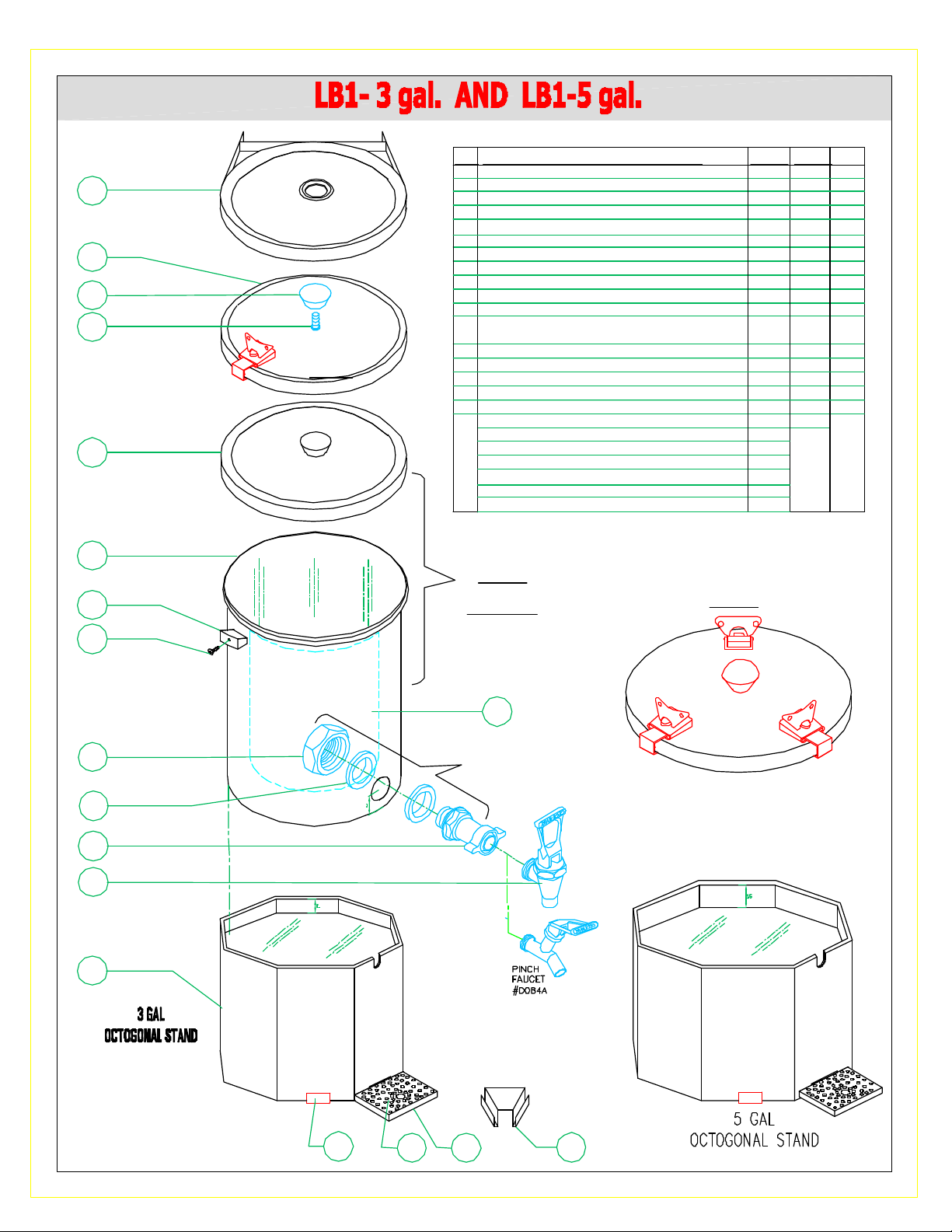
LB1-3.3 AND LB1-5 COMPONENTS DESCRIPTION
ITEM
SS BREW COVER [SHIPPED W/ MACHINE]
1
2
1
S.S. BREW COVER
SUPPLIED W/ MACHINE
2
3
4
BLACK S.S. COVER
W/ TWIST LATCH ASS'Y
SE39Q
5
BLACK MOLDED COVER
COVER, S.S., BLACK (COVER & LATCH ASS'Y SE39Q & SE40Q)
BLACK KNOB
3
SCREW, PAN HD 10-24 SS
4
MOLDED COVER - BLACK
5
6
TANK 3.3 GAL / 5 GAL [3 GAL. Q172A]
7
HANDLES - BLACK
8
HANDLE SCREW 8-32 x 1/2
NUT
9
BLACK WASHER, RUBBER
10
11
SHANK ASS'Y, W/PLASTIC WING NUT
12
S.S. FAUCET [WAS PLASTIC FAUCET DO77A]
or PINCH FAUCET USED W/BAG
OCTOGONAL BASE-10.5" HIGH - BLACK
13
14
EDGE WEAR STRIPS [SET OF 4]
15
GRILL - STAINLESS STEEL
16
DRIP TRAY PAN - BLACK
17
TOWER JOINT BRACKET- BLACK
18
WRAP LABEL- BRISK TEA - ICE CUBES [WAS NG08A]
WRAP LABEL- BRISK - YELLOW [WAS NF71A]
WRAP LABEL- JASMINE GREEN - GREEN [WAS NG09A]
WRAP LABEL- RASPBERRY - PINK [WAS NF73A]
WRAP LABEL- PEACH - PEACH [WAS NF72A]
WRAP LABEL- TROPICAL - BLUE [WAS NF74A]
WRAP LABEL- TEA BAR - GREEN [WAS NG92A]
LTB-303
Q184Q
Q080A
MO28A
P264A
M776A
Q181A
M632A
P015A
K105A
M080A
D025S
DO64A
DO84A
RT31A
M803A
RT34A
RT33A
RT35A
NH38A
NH41A
NH42A
NH43A
NH44A
NH45A
NH71A
LTB-505
Q190Q
R021A
MO28A
P264A
M777A
Q182A
M632A
P015A
K105A
M080A
D025S
D064A
D084A
RW47A
M803A
RT34A
RT33A
RT35A
NG32A
QTY
1
1
1
1
1
1
2
2
1
2
1
1
1
4
1
1
0/1/2
1
6
7
8
9
10
11
12
13
LABEL
TOP
ASS'Y
18
KIT Q195Q
BLACK S.S. COVER
W/ TWIST LATCH FOR LB1-5
SE40Q
14
15
16 17
21
Page 22

LB1-3 AND LB1-5 COMPONENTS DESCRIPTION
ITEM
SS BREW COVER [SHIPPED W/ MACHINE]
1
KNOB
2
SCREW, PAN HD 10-24
3
SS COVER - BLACK
4
TANK 3.3 GAL / 5 GAL [Q172A 3 GAL.]
5
HANDLES - BLACK
6
HANDLE SCREW 8-32 x 1/2
7
NUT
8
BLACK WASHER, RUBBER
9
SHANK ASS'Y, W/PLASTIC WING NUT - MODIFIED
10
S.S. FAUCET [WAS PLASTIC FAUCET DO77A] or
11
PINCH FAUCET USED W/BAG
S.S. ROUNDD BASE 9.43" HIGH
12
LABEL- ICE CUBES
1
S.S. BREW COVER
SUPPLIED W/ MACHINE
13
LB-3.3 gal.
Q184Q
MO28A
P264A
Q080A
Q181A
M632A
P015A
K105A
M080A
D025S
DO64A
DO84A
RZ86A
NH63A
LB-5 gal.
Q190Q
MO28A
P264A
R021A
Q182A
M632A
P015A
K105A
M080A
D025S
D064A
D084A
SA32A
NH63A
SU-10P
Q190Q
MO28A
P021A
R021A
K105A
M080A
D089A
D088A
NH63A
QTY
1
1
1
1
1
----
2
----
2
----
1
1
1
1
----
1
----
1
1
SU-10P
2
3
S.S. COVER
4
1
5
TOP
10
11
12
6
ASS'Y
7
2
3
4
LABEL
13
KIT Q195Q
8
9
5
8
9
22
11
13
Page 23

ITEM P/N DESCRIPTION FOR LB1-5 gal.
1 M027A KNOB
2 Q021A COVER - BLACK
3 P546A TWIST LATCH
4 SE39A PLATE, S.S. F/ GASKET
5 M768A GASKET, BUT SPLICED
6 P049A HEX BOLT 3/8-16x7/8
1
1
2
ITEM P/N DESCRIPTION
1 V226A AIRPOT - 3 Liters [3/4 Gal.]
2 M618A MOLDED TRAY - TRIPPLE
3 RV31A GRILL S.S. - TRIPPLE
4 M633A MOLDED TRAY - DOUBLE
5 RV30A GRILL S.S. - DOUBLE
6 M634A MOLDED TRAY - SINGLE
7 RV29A GRILL S.S. - SINGLE
2
3
4
5
6
ITEM P/N DESCRIPTION FOR LB1-3 gal.
1 M028A KNOB
2 P536A WELD STUD
3 Q080A COVER - BLACK
4 P546A TWIST LATCH
5 P264A SCREW, PAN HD 10-24 SS
3
4
5
1
2
6
3
7
4
5
23
Page 24
CECILWARE CORPORATION
Page 25

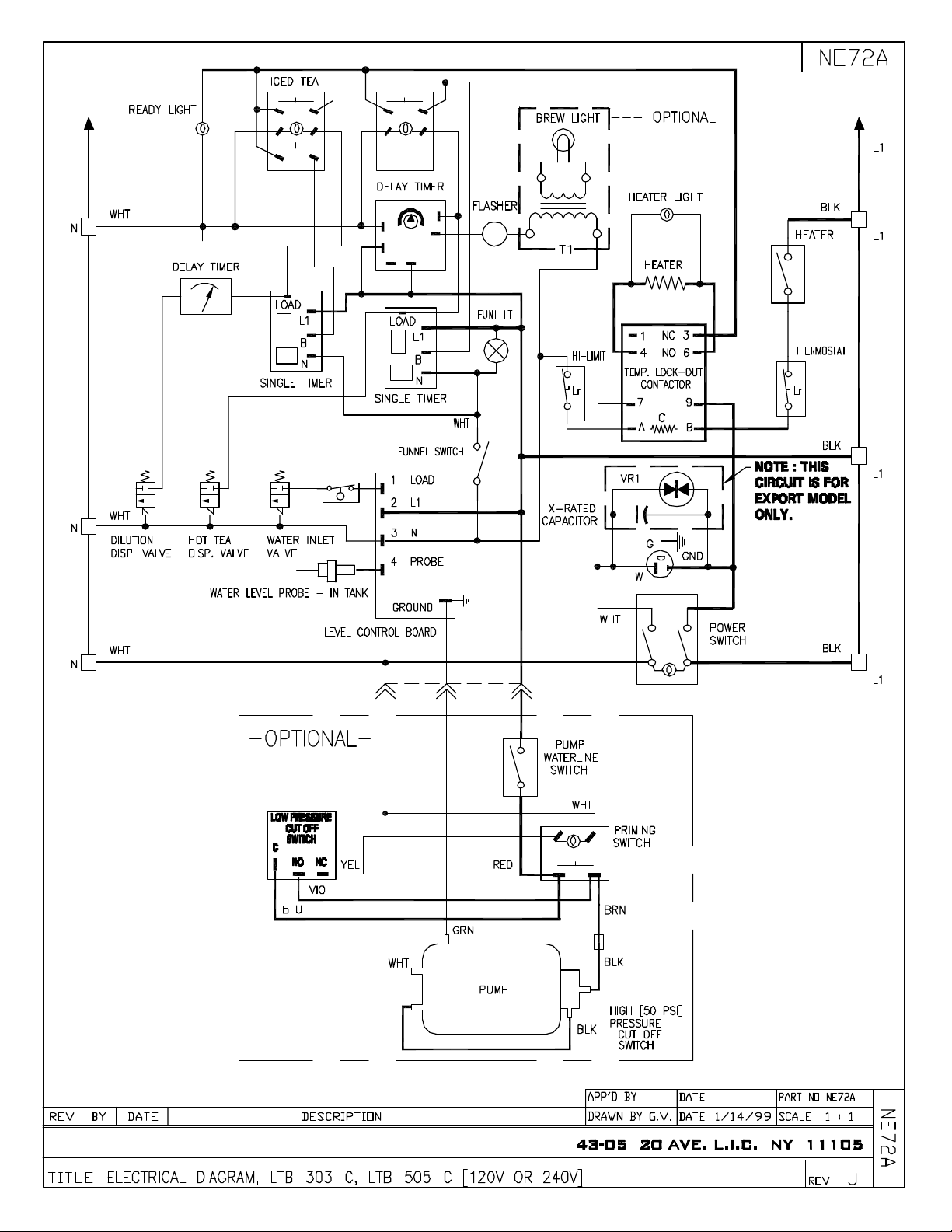
NOTE: THIS
CIRCUIT IS
FOR EXPORT
MODEL ONLY.
CECILWARE CORPORATION
Page 26

CECILWARE CORPORATION
Page 27

CECILWARE CORPORATION
 Loading...