

Page 1
0304 Form # AM-322-03
Part # 62280
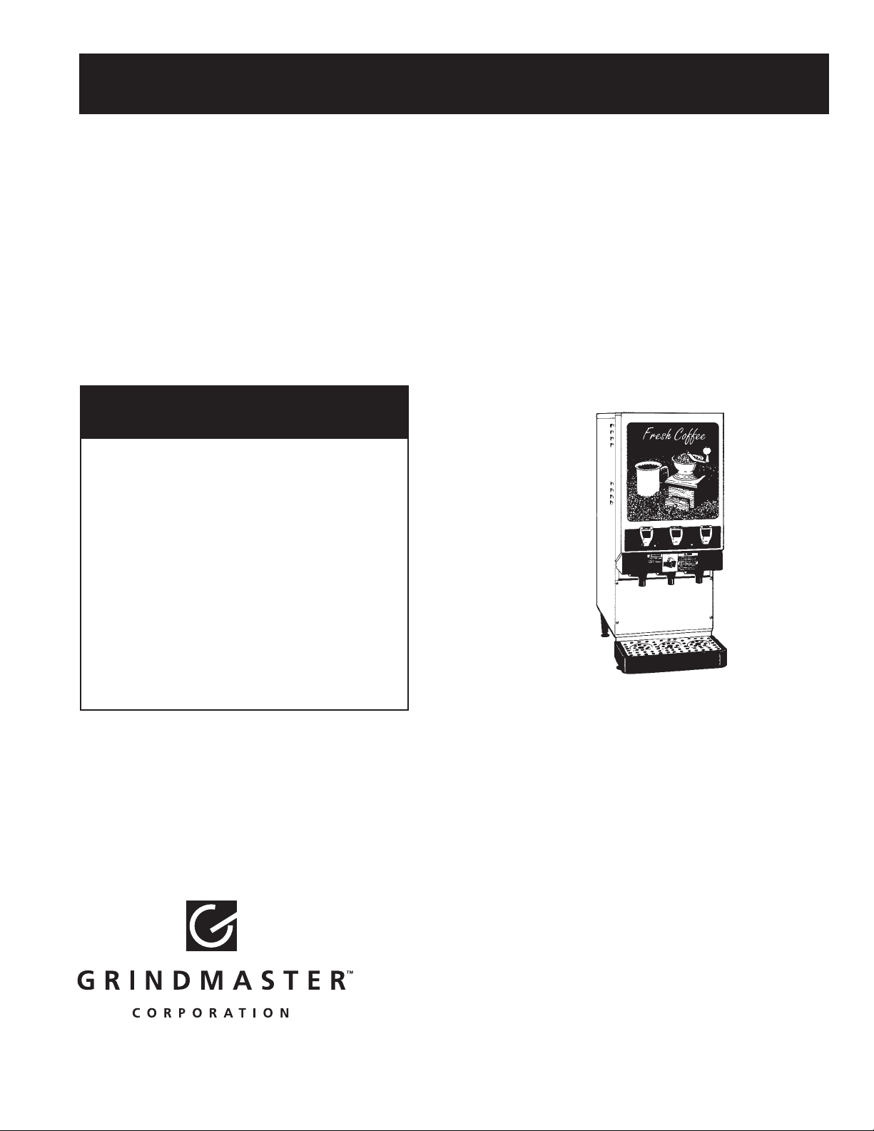
American Metal Ware®Liquid Coffee Dispenser
Operation and Instruction Manual
for
LCD2-1
& LCD2-3
© Grindmaster Corporation, 1998
Printed in USA
TABLE OF CONTENTS
Prior authorization must be obtained
from Grindmaster Corporation for all
warranty claims.
Warning Labels . . . . . . . . . . . . . . . . . . . . . .2
Installation . . . . . . . . . . . . . . . . . . . . . . . .3-4
How to Dispense a Cup of Coffee . . . . . . . . 4- 5
Adjustments . . . . . . . . . . . . . . . . . . . . . .5-6
Drink Strength Adjustment . . . . . . . . . . . .5-6
Service and Cleaning . . . . . . . . . . . . . . 6-9
Troubleshooting Guide . . . . . . . . . . . .10-11
Exploded Views . . . . . . . . . . . . . . . . . .12-17
Wiring Diagrams . . . . . . . . . . . . . . . . .18-23
Grindmaster Corporation
4003 Collins Lane
Louisville, Kentucky 40245
(502) 425-4776 800-695-4500
(800) 568-5715 (technical service only)
FAX (502) 425-4664
www.grindmaster.com
Models LCD2-1 & LCD2-3
Page 2
American Metal Ware Liquid Coffee Dispenser Page 2
Warning Labels
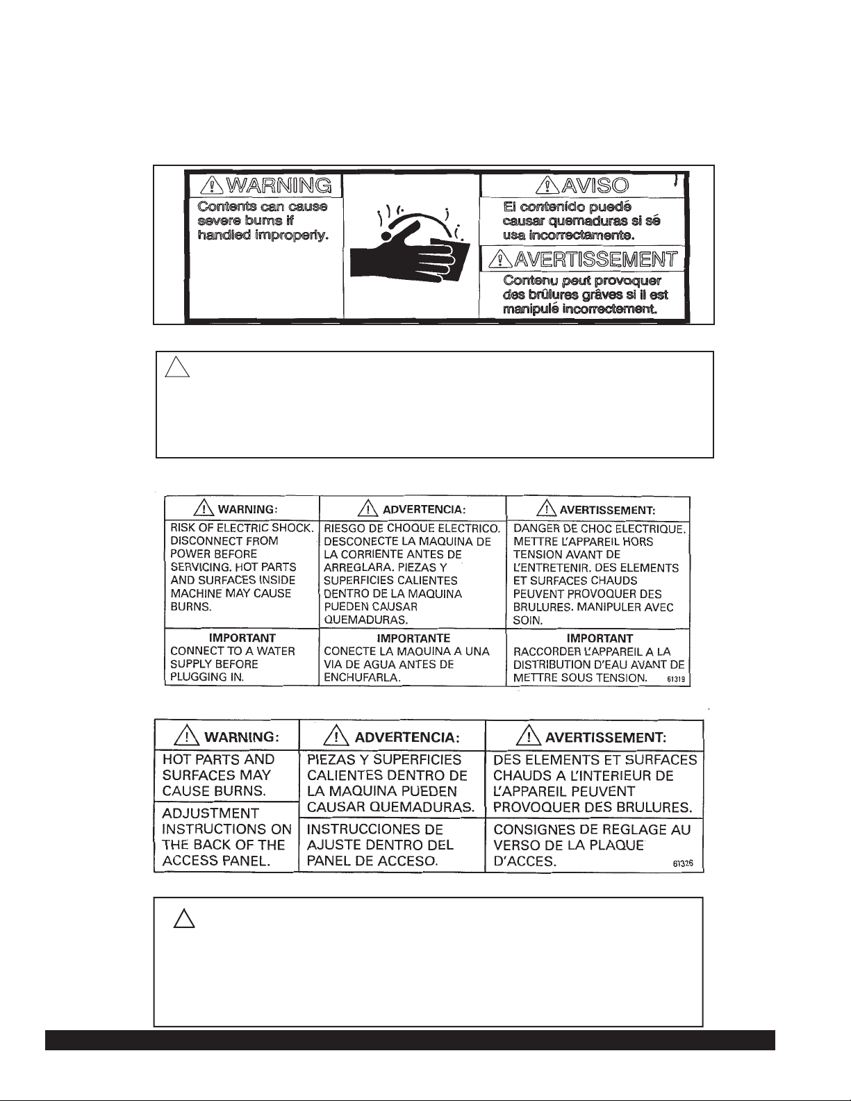
The following warning labels were on your dispenser when it was shipped from the factory. They
should remain on your dispenser in good, readable condition at all times. If one of your labels is
missing or damaged, order a replacement label immediately.
!
Part #62243, Located on merchandising door valance on front of dispenser
Part #61321, Located behind the drip pan on the front of the dispenser
!
WARNING: Risk of electric shock. Disconnect from power before servicing.
Hot parts and surfaces inside and outside machine may cause burns. Tank drain
hose inside machine dispenses very hot water. Will cause burns and/or personal
injury. Must have five gallon heat resistant container to catch hot water. Hot water
may splash. Do not attempt to stop hot water once it begins flowing. Replace plug
and clamp prior to refilling tank.
Part #61319, Located on the outside on the back of the dispenser
Part #61326, Located on the outside on the left of the dispenser
Part #61325, Located on the drain hose inside the dispenser
ADVERTENCIA
AUGU MUY CALIENTE PUEDE CAUSAR QUEMADURAS
IMPORTANTE
UD DEBE TENER UN RECIPIENTE RESISTENTE AL CALOR DE CINCO (5)
GALONES PARAQUARDAR AGUACALIENTE. PARAVACIAR ELAGUA CATIENTE
DEL DEPOSITO, QUITE LA ABRAZADERA, APRETE EL TUBBO Y DESCONECTE
LA MANGUERA. NO TRATE DE DETENER EL AGUA UNA VEZ QUE EMPIECE A
FLUIR. REEMPLACE ELTAPONYY SUGETE ELTURBO ANTES DE RELLENAR EL
DEPOSITO.
AVERTISSEMENT
L'EAU TRES CHAUDE PEUT PROVOQUER DES BRULURES
IMPORTANT
IL FAUT UN RECIPIENT RESISTANT A LA CHALEUR D'UNE CAPACITE DE 5
GALLONS (19 LITRES) POUR RECUEILLIR L'EAU CHAUDE DU RESERVOIR.
POUR VIDER LE RESERVOIR, SENLEVER LE SERRE-JOINT, PINCER LE TUBE ET
RETIRER LE TUYAU. NE PAS ARRETER L'ECOULEMENT D'LEAU. AVANT DE
REMPLIR A NOUVEAU LE RESERFVOIR. REPLACE LA FICHE ET LE SERRE
JOINT.
WARNING
Very hot water may cause burns
IMPORTANT
- You must have a 5 gallon heat resistant container to
catch hot water.
- To empty hot water from tank remove clamp, pinch
the tube and unplug hose. Do not attempt to stop
water once it begins flowing.
- Replace plug and clamp prior to refilling tank.
Page 3
Installation
Water Inlet Connection:
The National Sanitation Foundation requires the following for an NSF approved water hook-up:
1. A quick disconnect water connection or enough coiled tubing so that the machine can be moved for cleaning
underneath.
2. An approved backflow prevention device, such as a double check valve to be installed between the machine and
water supply. A1/4" male flare adapter is provided (packed inside drain tray) to be attached by installer to the
back of the machine for hook-up to water supply. On units plumbed to permanent water line, installation of a water
filter/softener system is recommended to prevent lime and scale build up in the machine. On units pumping from
remote water container, filtered water is recommended to prevent lime and scale buildup in the machine.
3. Water pipe connections and fixtures directly connected to potable water supply shall be sized, installed and
maintained in accordance with Federal, State, and Local codes.
Water hook-up:
1. Install the (2) front 4" legs to provide approximately 1/2" clearance with the bottom of the machine.
2. Install drain tray bracket to the front of the machine by sliding the bracket between the front 4" legs and the
bottom of the machine. The bracket should self locate with screw heads on the bottom of the machine. Tighten
the front 4" legs to secure the drain tray bracket.
3. Install the (2) back 4" legs and tighten.
4. Install the plastic drain tray onto the drain tray bracket. (Note: The drain tray is provided with a removable plug to
allow for plumbing the drain tray to a drain.)
5. Connect the metal swivel fitting provided to a flexible water supply hose. Ensure the water supply hose has
sufficient length to allow the machine to be moved for cleaning or service. Supplying hot water to the machine will
greatly increase the capacity of the machine. The use of copper tubing is required to prevent rupture when using
a hot water supply. Amaximum inlet water temperature of 160Þ F is recommended.
6. Ensure that the water supply to the machine is within 20 to 100psi. Install a pressure regulator if pressure is too
high.
American Metal Ware Liquid Coffee Dispenser Page 3
!
WARNING: ELECTRIC SHOCK HAZARD
Only qualified service personnel should perform installation of this appliance.
Improper installation could result in serious injury or death.
!
WARNING: ELECTRIC SHOCK HAZARD
Never use the ground conductor as a neutral conductor. Serious injury or
death could occur in the event of a fault condition.
!
WARNING: ELECTRIC SHOCK HAZARD
Always disconnect power to the machine before servicing or cleaning. Risk
of electric shock is present which can cause serious injury or death.
Page 4

American Metal Ware Liquid Coffee Dispenser Page 4
Installation (cont.)
Electrical Hook-up: Ensure water connection is made to machine before proceeding
The electrical ratings for your dispenser are located on the serial plate on the outside cabinet. For configuration of
three heater models to optional wattages, refer to configuration manual 62210 supplied with the machine.
1. For cord connected models, plug the power cord into an appropriate grounded and dedicated electrical outlet.
Go to step 8.
2. For hard-wired models not supplied with a can electrical cord, the dispenser should be connected to a dedicated
circuit with a fused disconnect switch or a circuit breaker near the dispenser.
3. Strain relief knockouts are supplied on the back of the machine chassis for power entry.
• Electrical connections and wiring materials must conform to local codes and/or be in compliance with
the National Electric Code
• Use only copper conductors
4. Remove the access panel located on the upper left side of the dispenser. Note: wiring diagram is on backside
of access panel.
5. Connect the power supply conductors, neutral and ground wire to the appropriate positions on the terminal block
located on the upper left side of the dispenser. The ground lug is separate from the terminal block. Note: if
power supply available does not provide for a neutral conductor, a stepdown transformer must be installed to
provide the necessary 120 volt power supply for the control circuits. Consult factory for assistance.
6. Install the side access panel.
7. Flip power supply to machine “ON” at the branch supply disconnect.
8. Flip power switch to the “ON” position and allow the water tank to fill. The machine will make a subtle hissing
sound while filling. Allow 3-4 minutes for fill time depending on water pressure.
9. After the water tank has completed the fill cycle, the green Ready light located on the front of the dispenser
should extinguish signifying that the heating element has been activated. Allow 10-60 minutes for the Ready light
to illuminate signifying the water tank has reached operating temperature. (Note: Heatup time is dependent on
water inlet temperature and input wattage to the machine.)
Bag-in-Box Hook-up
1. Place bag-in-box containers inside the cabinet behind the front door. Connect the quick connect fitting to each
bag-in-box.
2. After connecting the bag-in-box, flip the water switch located behind the front door to the “OFF” position and flip
the concentrate switch to the “ON” position.
3. Activate the appropriate dispense switch on the front of the door in order to prime the concentrate lines with
product. Continue to activate the dispense switch until concentrate is dispensed from the appropriate dispense
spout.
4. Repeat steps for other dispense spout.
5. Flip water switch back to “ON” position.
6. Close front door and ensure that both water and product are dispensed simultaneously.
How to Dispense a Cup of Coffee
Attention: This machine employs an interlock switch to disable the dispense and fill circuits
when the front door is open. Ensure the front door is closed while installing or operating the
machine. A watchdog circuit also monitors the water level in the tank and will disable the
machine if the water level in the tank is not normal within (5) minutes of fill time. The machine
will require power to be reset to clear the watchdog timeout.
WARNING:
Do not use cups over 6 3/4" (15.2 cm) tall with this machine. Use of cups over this height could
result in severed burns and injury.
!
Page 5
American Metal Ware Liquid Coffee Dispenser Page 5
How to Dispense a Cup of Coffee (cont.)
On models with manual dispense switches:
1. Place a cup under the selected drink dispense nozzle.
2. Push and hold dispense switch until cup is full and then release switch.
On models with portion control dispense switches:
1. Place a cup under the selected drink dispense nozzle.
2. Push button for one second, then release to dispense one serving.
Note: Portion may be cancelled by push and release of the switch.
Adjustments
Portion Adjustment (Portion control units only)
1. Place a cup under the selected drink dispense nozzle.
2. Press and hold the desired dispense switch and press and release the manual top-off button to activate the
programming sequence.
3. After a 10 second time delay, the machine is triggered into program mode and will begin dispensing.
4. Continue pressing the button until cup is full, then release the switch to prevent overfill. The elapsed portion
dispense time is saved to memory and will remain until the dispense switch is reprogrammed.
5. Check the portion size by placing an empty cup under the desired dispense nozzle, then press and release
the dispense switch. The machine will dispense the preprogrammed portion size.
6. If the portion size is incorrect, repeat steps 1, 2, 3, 4 & 5 until the desired portion size is achieved.
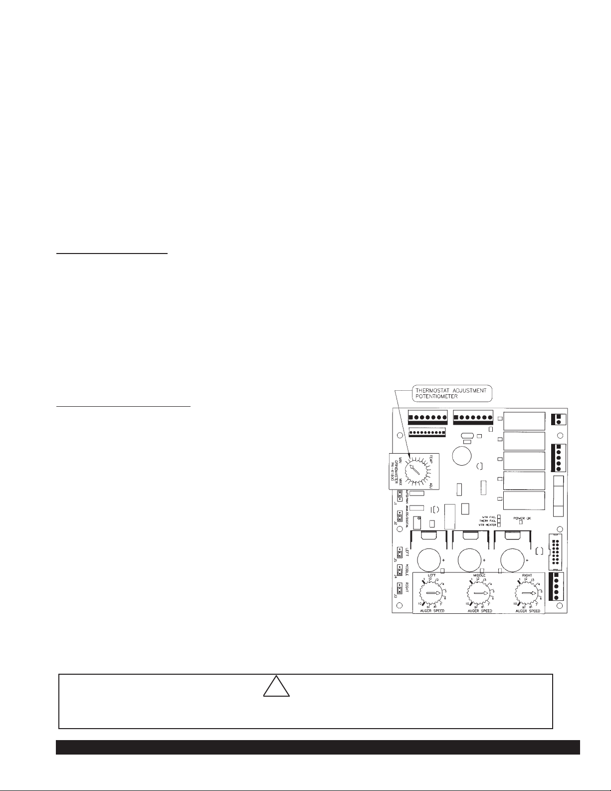
Thermostat
Adjustment
(Refer to Figure A)
Note: The thermostat range is approximately
160° to 200°F (71.11°C to 93.33°C). The tank temperature
is factory set at 190°F (87.78°C), making beverage
temperature slightly lower than 190°F (87.78°C).
The factory setting is recommended for liquid coffee based
concentrates. Other products may require different mixing
temperatures. Follow product manufacturer’s recommended
mixing water temperature for non-coffee products.
Temperature can be adjusted as follows:
Tool required: #2 Phillips screwdriver.
1. Unplug machine.
2. Remove the drip pan.
3. Remove the upper splash panel on the front of the machine
by removing the (4) Phillips head screws.
4. Remove control panel cover by loosening (2) screws enough
to allow keyholes in panel to clear the screw heads.
5. Locate the thermostat adjustment dial on the left side of the
control board. (Refer to Figure A)
6. To adjust the temperature of the water being dispensed, turn the adjustment dial on the control board. (Turn
clockwise to increase the water temperature or counter clockwise to decrease the water temperature.)
Figure A
!
CAUTION!
Do not force the adjustment dial beyond its 270 degrees of rotation or damage to the control board may
occur.
Page 6
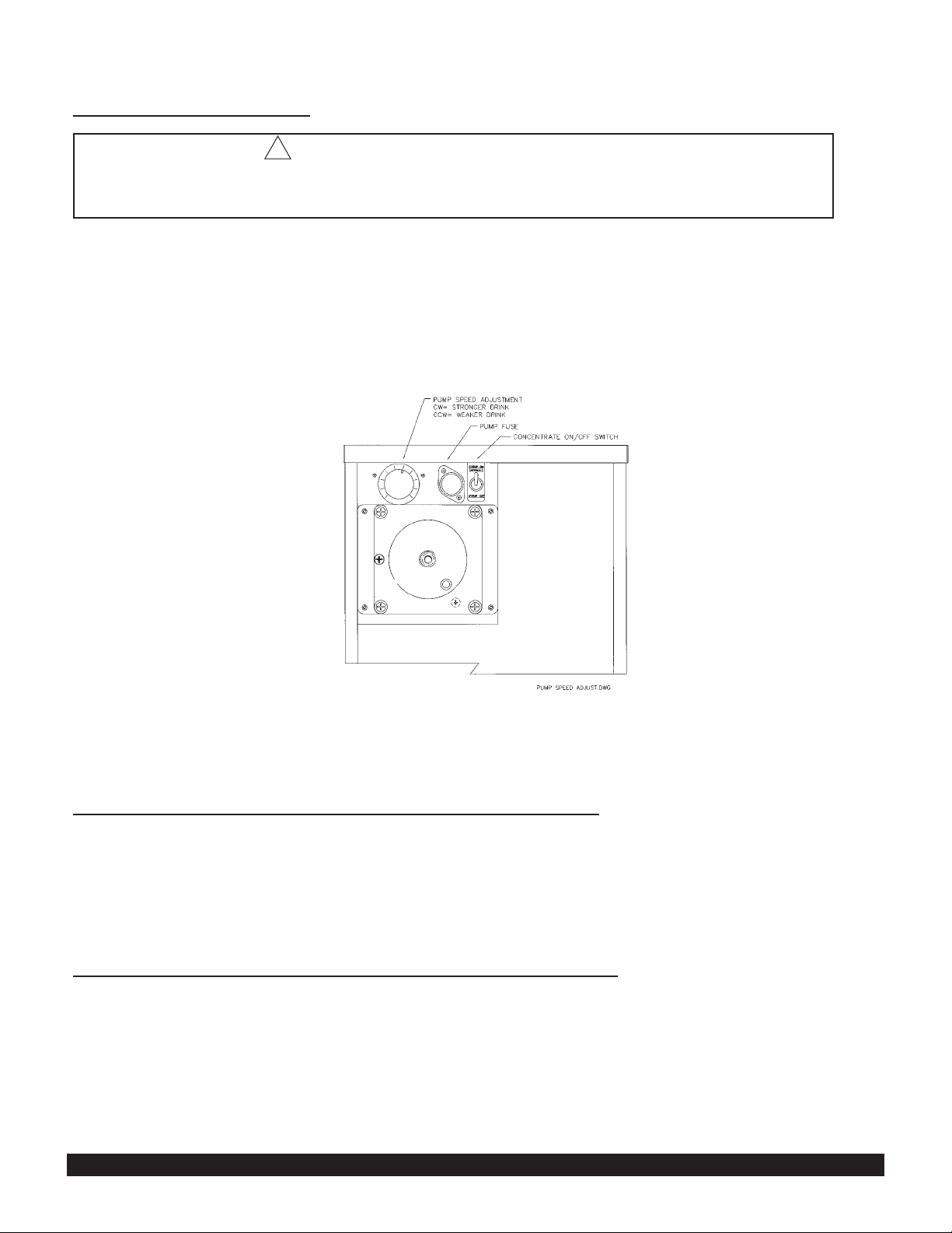
Adjustments (cont.)
Drink S
trength Adjustment
(Refer to Figure A& B)
Tools required: #2 Phillips Screwdriver
1. Dispense a drink to determine if drink is too strong or weak.
2. Turn off power to machine at power switch.
3. Remove front splash panel below dispense heads in front of machine.
4. Locate the mix ratio setting panel directly behind the front splash panel (see Figure B)
5. Adjust drink strength by determining the digital setting for the desired mix ratio. (Note: Clockwise will strengthen
product, counterclockwise will weaken the product.)
Note: (For Hot Chocolate see figure B and follow the same steps as above.)
Service and Cleaning
Daily Cleaning Instructions for the LCD Coffee Dispensers:
1. Wipe down all stainless steel surfaces of the dispense spout, bag-in-box cabinetry and drip tray areas with a clean
soft cloth using a mixture of one oz. (28 g) Ivory liquid detergent or equivalent to one gallon (3.8 litre) of fresh water.
2. Follow by wiping down all stainless steel surfaces of the dispense spout and cabinetry with a clean soft cloth
moistened with fresh water and allow to air dry.
3. Remove drain tray and wash in a three compartment sink with warm soapy water per above concentration until all
signs of product residue are removed, rinse thoroughly with fresh water and air dry.
Weekly Cleaning Instructions for the LCD Coffee Dispensers:
1. Flip water switch (a) to “OFF” position.
2. Remove fitting cap (a) from bag-in-box quick disconnect fitting then remove internal check valve parts by rotating the
retaining cap at the opposite end of the o-ring end. This will allow free flow of sanitizing solution through the
connector and faster cleaning.
2a. For Hot Chocolate disconnect BIB fitting and insert Scholle probe sanitizing attachment (not provided).
3. Insert the bag-in-box quick disconnect fitting into a one gallon (3.8 litre) basin of very warm (150°F/65.56°C) soapy
water. Use 1/2 oz. (14 g) Ivory liquid detergent or equivalent to one gallon (3.8 litre) of water.
4. Push and hold the corresponding dispense switch until clear soapy water is dispensed from the spout.
American Metal Ware Liquid Coffee Dispenser Page 6
Figure B
WARNING: ELECTRIC SHOCK HAZARD
Always disconnect power to the machine before servicing or cleaning. Risk of electric
shock is present which can cause serious injury or death.
!
Page 7

Service and Cleaning (cont.)
Weekly Cleaning Instructions for the LCD Coffee Dispensers: (cont.)
5. Flush soapy water by repeating steps 3 and 4 using one gallon (3.8 litre) of very warm (150°F/65.56°C) water
without soap.
6. Prepare one gallon (3.8 liter) of food grade sanitizing solution in a container per manufacturer’s recommendations
and repeat step (4) until sanitizing solution is dispensed from the spout. Let sanitizing solution work for 5 minutes,
then flush the concentrate line by pushing and holding the dispense switch until the sanitizing solution dispenses
clear.
(Note: recommended sanitizing solution is KAY-5 Sanitizer/Cleaner; mix one oz. (28 g) packet of sanitizer powder
+ 2 1/2 gallons (9.5 litre) of warm (approximately 120°F/48.89°C) water to achieve a solution of 100ppm of
available chlorine).
7. Remove the bag-in-box connector from the sanitizing solution basin and purge the concentrate line by pushing and
holding the dispense switch until the concentrate tube runs dry.
8. Flush the concentrate line with fresh water by submerging the bag-in-box connector in a one gallon (3.8 litre)
container of fresh tap water and activating the corresponding dispense switch for one minute.
9. Re-assemble the bag-in-box connector, then reconnect the bag-in-box connector to a bag-in-box of concentrate.
10. Prime the concentrate line by pushing and holding the dispense switch until concentrate drips from the spout.
11. Flip the water switch to the “ON” position and dispense and discard (2) 6 oz. (168 g) drinks.
12. Repeat all steps for other dispense heads.
To prepare for shipment: Important - Always completely empty water tank and remove bag in box containers
prior to shipping unit. (See Draining the Tank and Cleaning the Concentrate Line Sections). Purge concentrate
lines.
Draining the Tank
Always empty the tank before shipping.
WARNING: Draining of tank should be performed by a qualified service technician. The tank contains
4 1/2 gallons (17.1 litre) of very hot water. May cause severe burns.
1. Prepare a 5 gallon (17.5 litre) heat resistant container to drain the tank water into.
2. Unplug the machine.
3. Remove the drain tray and front access panel.
4. Locate the silicone drain hose on the left side wall. Put the end of the drain hose into the bucket.
Secure the end of the drain hose (i.e. with tape) into the bucket.
5. Remove the hose clamp and plug.
6. Allow the tank to drain completely.
WARNING: Do not attempt to stop the flow of water once it begins to drain.
7. Once the tank is empty, securely replace the plug and clamp on the end of the hose. Reposition the drain
hose inside the hose clip on the left side wall.
8. Reassemble the front access panel and drain tray.
Purging Machine of all Water for Shipment in Cold Areas
WARNING: This procedure should be performed by a qualified service technician.
The unit can be purged of water as follows:
1. Turn the power switch to the "OFF" position.
2. Drain the water tank (refer to instructions on Page 6.) Do not replace the drain hose plug and clamp until
further instructed.
3. Turn the power switch to the "ON" position. The Ready light should turn itself on within 12 seconds. The 12
second delay signals that the heating element has been disabled due to the lack of water in the tank after it is
drained. Important: If the Ready light does not turn itself on within 12 seconds, turn the power off to
avoid burning out the heating element.
4. Listen for the inlet valve to energize. To purge the inlet valve and water inlet tube, apply 10-20 psi compressed air
to the inlet valve connection for 10 to 20 seconds while the inlet valve is energized. Note: Do not energize the
inlet valve for more than 5 minutes at a time. Otherwise, the watchdog timer will disable the inlet valve. If this
occurs, reset the machine by flipping the power switch off then on.
American Metal Ware Liquid Coffee Dispenser Page 7
Page 8
American Metal Ware Liquid Coffee Dispenser Page 8
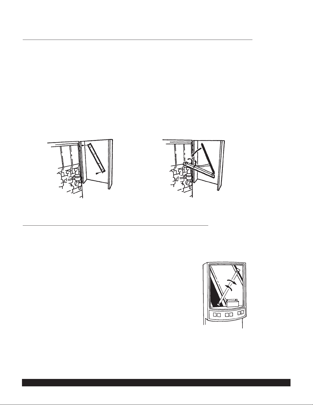
Figure C
Figure D
Service and Cleaning (cont.)
Changing the Lightbulb on Stainless Steel Models with a Backlit Merchandiser
(Refer to Figures C and D)
(Refer to serial tag to verify model number of your machine)
WARNING: Disconnect machine from branch electrical supply before changing the lightbulb
Note: The machine uses a F8T5 12" (30cm) 8 watt replacement bulb.
1. Open the merchandiser door.
2. Remove the (2) screws at each end of the lightbulb panel inside the door.
3. The panel will come down to allow the bulb to be changed.
4. Remove the old lightbulb by gently turning the lightbulb 1/4 turn to the left and pulling the bulb from the socket.
5. Install the new bulb by lining the pins on either end of the bulb parallel with the socket opening.
6. Gently insert both ends of the bulb into the socket and turn the bulb 1/4 turn to the right until the bulb locks into
place.
7. Replace the lightbulb panel. Reinstall the screws.
Changing the Lightbulb on Models W
ith a Backlit Merchandiser
(Refer to Figure E)
(Refer to serial tag to verify model number of your machine)
WARNING: Disconnect machine from branch electrical supply before changing the lightbulb.
Note: The machine uses a F8T5 12" (30cm) 8 watt replacement bulb.
1. Remove the front merchandiser photo and cover by grasping
the edges of the merchandiser.
2. Remove the old lightbulb by gently turning the lightbulb
1/4 turn to the left and pulling the bulb from the socket.
3. Install the new bulb by lining up the pins on either
end of the bulb parallel with the socket opening.
4. Gently insert both ends of the bulb into the socket
and turn the bulb 1/4 turn to the right until the bulb
locks into place.
5. Replace the merchandiser photo and cover.
Figure E
Page 9

American Metal Ware Liquid Coffee Dispenser Page 9
ORDERING PARTS/SERVICE
Grindmaster Corporation
4003 Collins Lane
Louisville, KY 40245
1-800-695-4500
Date of Installation:________________________
Data Plate
The data plate provides necessary information that
the operator should record and refer to when calling for parts or service. The data plate for the
LCD 2 is located on the right side panel in the
lower left hand corner.
Complete for quick reference when this information
is requested.
1. Model Number: _______________________
2. Serial Number: ________________________
Electrical Specs:
3. Phase ______
4. Watts ______
5. Volts ______
6. Cycle ______
7. Circuit Breaker Size: ______________Amps
Service and Cleaning (cont.)
Control Diagnostic Diagram
GRINDMASTER CORPORATION
Diagnostics for PIC3-3 PORTION CONTROLLER:
WTR FAIL = Light flashes when watchdog timer disables
machine after 300 seconds of continuous inlet valve
operation.
THERM FAIL = Light flashes when thermistor fails or
thermistor is disconnected.
WTR HEATER = Light flashes when heater is on.
POWER OK = Light stays on when transformer is supplying
proper voltage to controller.
FRONT VIEW OF CONTROLLER (LOCATED BEHIND DRAIN PAN)
Page 10

American Metal Ware Liquid Coffee Dispenser Page 10
Troubleshooting Guide
The following procedures must be performed by a qualified service technician.
Machine does not power up
• Machine is unplugged
• Circuit breaker behind door has tripped
• Ensure machine is plugged into power supply
• Reset breaker
Hot Chocolate will not pump
• Vacuum leaking in tube or BIB fitting
• Ensure product viscosity is not too high
• Ensure product tubing is not too long
• BIB empty. Change box
• Ensure there is no leak in the pump tubing
• Ensure the pump fuse is not blown
• Ensure that the concentrate switch is turned on
No hot water from dispense head
• Door is open (An interlock switch disables
the dispense and fill circuits when the door
is open)
• Faulty thermistor
• Faulty water tank heater
• Fill circuit watchdog timer has tripped
• Water switch is in “OFF” position
• Water supply to machine is turned off
• Check for flashing diagnostic lights on
control board
• Ensure door is latched closed. Reset power to
machine to ensure fill circuit watchdog timer is
reset
• Consult factory for assistance
• Check for open heater and replace if necessary
• Ensure water supply to machine is on and reset
power to machine. Green Ready light off indicates
heater is activated and tank is heating
• Ensure switch is in “ON” position
• Ensure water supply is on then reset power to the
machine to reset the fill circuit watchdog timer
• See Control Diagnostic Diagram for explanation
of lights
No concentrate is dispensed
• Concentrate switch is in “OFF” position
• Bag-in-box is empty
• Bag-in-box connector is pointing up (This
position can create a partial vacuum in the
concentrate tube which may prevent product from being pumped to the dispense
spout)
• Concentrate pickup tube is kinked
• Concentrate pump tubing is clogged
• Ensure switch is in “ON” position
• Ensure bag-in-box is not empty; replace with new
bag-in-box if empty
• Position bag-in-box with connector pointing down
to provide a positive pressure in the concentrate
tube
• Inspect tubing routing and ensure concentrate
tubing is not kinked
• Periodically clean and sanitize tubing per the
Cleaning and Sanitizing procedure section in
this instruction manual
Machine does not dispense or fill
• Transformer is blown
• Blown fuse on controller
• (Refer to Control Diagnostic diagram) Check if
green LED on control board is illuminated when
machine is powered on. Green LED indicates that
control is receiving proper supply voltage from
transformer. Replace transformer if LED does not
illuminate.
• Check fuse and replace if necessary
Water tank slowly overflows through tank
vent at bottom of machine
• Weeping fill valve seat
• Replace fill valve
Problem/Cause
Remedy
Page 11

American Metal Ware Liquid Coffee Dispenser Page 11
Water tank overflows through tank vent at
bottom of machine
• Faulty or corroded level probe
• Faulty level control circuit wiring
• Faulty control board
• Inlet water pressure too high
• Remove probe and remove any scale or mineral
buildup and reinstall in water tank grommet
• Ensure both probe ground connections are
securely fastened to water tank top
• Consult factory for help, replace control if necessary
• Ensure water pressure is below 100 psi
Water tank boils
• Temperature setting too high for elevation
of installation
• Heater contactor stuck in closed position
• Faulty control
• Faulty thermistor
• Adjust temperature down, refer to Thermostat
Adjustment Section in installation manual
• Check if green Ready light on front of machine is
on when machine is boiling. Ready light on indicates that the control has deactivated the heater
circuit. Replace contactor if machine boils with
Ready light on.
• Ensure that Ready light is off when machine boils
and that that machine does not respond to
temperature adjustment downward. Consult factory
for assistance.
• Consult factory for assistance
Water is cold when dispensed
• Fill circuit watchdog timer has been
activated
• Faulty thermistor
• Faulty water tank heater
• Ensure water supply to machine is on and reset
power to machine to reset watchdog timer
• Check if Red “Therm/Fail” LED is illuminated.
Replace thermistor if LED is illuminated
• Check for “open” heater and replace if necessary
Drink is too weak or strong
• Refer to Drink Strength Adjustment section
Drink is too hot or cold
• Refer to Thermostat Adjustment section
Off taste of coffee
• Poor water quality, to include high chlorine level,
heavy mineral concentration or stale water
• Addition of a taste and odor filter to incoming water
• Drain water from tank, remove and delime. If
necessary, flush tank with fresh water.
Troubleshooting Guide (cont.)
Problem/Cause
Remedy
If you still need help, call our service department at (800) 695-4500 (Monday through Friday, 8 am - 6 pm EST) or an authorized service
center in your area. Please have the model and serial numbers ready so that accurate information may be given.
Prior authorization must be obtained from Grindmaster Corporation’s Technical Services Department for all warranty claims.
Page 12

Exploded Views LCD2-1 and LCD2-3
American Metal Ware Liquid Coffee Dispenser Page 12
Page 13

American Metal Ware Liquid Coffee Dispenser Page 13
Exploded Views LCD2-1 and LCD2-3
Page 14

American Metal Ware Liquid Coffee Dispenser Page 14
Exploded Views LCD2-1 and LCD2-3
Page 15

American Metal Ware Liquid Coffee Dispenser Page 15
Exploded Views LCD2-1 and LCD2-3
Page 16

American Metal Ware Liquid Coffee Dispenser Page 16
Exploded Views Optional 130VA Stepdown Transformer Parts List
ITEM P/N DESCRIPTION
1 62392 DECAL, 1.5A FUSE
2 62332 FUSEHOLDER
3 62386 FUSE, 1.5 AMP CLASS CC
4 07026-02 SCREW, 8-32 X 1/2
5 62402 HARNESS, 130VASTEPDOWN
6 62289 WIRE NUT
7 61353 SCREW, 8-32 X 1/4
8 62364 TRANSFORMER, 130VASTEPDOWN
9 62401 PLATE, TRANSFORMER MOUNTING
10 62355 PLATE, OFFSET SS SIDE ACCESS
11 71129 NUT, 8-32 KEPS
Page 17

American Metal Ware Liquid Coffee Dispenser Page 17
Exploded Views High Volume Remote BIB Applications
ITEM P/N DESCRIPTION
1 62383 BRACKET, HOPPER
2 62387 FITTING, 3/8 X 5/8 BARB
3 88031 BUSHING, 3/4 HEYCO
5 62333 FITTING, SCHOLLE PROBE BIB
6 62366 CLAMP, 15/16 OETIKER
7 62343 BUSHING, 1 3/8 HEYCO
8 62361 FITTING, 1" NPT LIQUI-TIGHT
9 62365 TUBING, 5/8 ID X 15/16 OD
10 62373 FITTING, "Y" TUBING
11 62362 NUT, 1" NPT
12 62404 HARNESS, CHASSIS
13 62358 HARNESS, 90VDC PUMP
14 07206-06 NUT 6-32 SS
15 07026-07 SCREW, 8-32 X 3/8 SS
16 62371 BRACKET, PUMP
17 62356 PUMP, 90VDC PERISTALTIC
18 07023-04 SCREW, 6-32 X 1/4
20 62386 FUSE, 1 1/2 AMP CLASS CC
ITEM P/N DESCRIPTION
21 62332 FUSEHOLDER
22 62368 DECAL, FLUSH
24 62372 SWITCH, SPST
25 61820 HARNESS, DOOR INTERCONNECT
26 62357 HARNESS, HOPPER BRACKET
27 61133 SWITCH, 3PST
28 62367 GRAPHIC, CHOCOLATE
29 62369 DECAL, PULL SWITCH W/O P/O
30 62370 BRACKET, 90 VDC PUMP SIDE
31 62392 DECAL, 1.5 AMP FUSE
32 71129 NUT, 8-32 KEPS
33 90360 VALVE, BEVERAGE
34 62384 BRACKET, BEVERAGE VALVE
35 62385 COVER, BEVERAGE VALVE
36 82030 SCREW, #10 X 1/2
37 07348-01 POP RIVET
38 60593 CLAMP, 1/2" OETIKER
39 62405 TUBING, 1/4 ID X 1/8 WALL
40 07327 CLAMP, 5/8 ID HOSE
Page 18

American Metal Ware Liquid Coffee Dispenser Page 18
Wiring Diagram 120/240V
Page 19

American Metal Ware Liquid Coffee Dispenser Page 19
Wiring Diagram 120/240V
Page 20

American Metal Ware Liquid Coffee Dispenser Page 20
Wiring Diagram
Rev. Release
Page 21

American Metal Ware Liquid Coffee Dispenser Page 21
Wiring Diagram
Page 22

American Metal Ware Liquid Coffee Dispenser Page 22
Wiring Diagram for High Volume, Remote BIB Applications
Page 23

American Metal Ware Liquid Coffee Dispenser Page 23
Wiring Diagram for High Volume, Remote BIB Applications
Page 24

AMERICAN METAL WARE
WARRANTY
For Model LCD2
EFFECTIVE SEPTEMBER 22, 1998
GENERAL WARRANTY INFORMATION
Grindmaster Corporation maintains the highest standard of quality control in the manufacturing of American Metal
Ware products. We use the finest components and materials, and employ quality engineering standards
and tests. All American Metal Ware LCD Dispensers will be warranted against defects in materials and workmanship
for a period of one year from the date of shipment. This warranty will include parts and labor, but will not cover
transportation and shipping charges and will be limited to equipment sold to commercial purchasers and installed
in the continental U.S.A., Hawaii, Alaska and Canada.
EXCEPTIONS
Coverage is not included for labor needed or caused by:
• This warranty does not cover temporary non functioning conditions which can occur with normal use and
which can be readily remedied by the user by referring to the user’s instructions or calling Grindmaster
Corporation’s toll free Hot Line (800-695-4500) for assistance. These temporary nonfunctioning
conditions include:
• Drink strength, flow rate & portion adjustments
• Reset of the dispenser after the watchdog timer has activated
• No concentrate flow because the dispenser was left in the rinse cycle
• This warranty does not cover maintenance consumable parts such as o-rings & seals, and pump tubing.
These are subject to NORMAL wear or everyday usage and are a responsibility of the user.
• Accident
• Improper installation
• Neglect or abuse
• Excessive lime/mineral content of water used
• Cleaning of any category. Cleaning is a user’s responsibility.
• Incorrect voltage
NOTE: THIS WARRANTY SUPERSEDES ANY OTHER WARRANTY. ALL OTHER WARRANTIES,
EXPRESSED OR IMPLIED, INCLUDING THE WARRANTIES OR MERCHANTABILITY AND FITNESS FOR A
PARTICULAR PURPOSE OR USE, ARE HEREBY EXCLUDED AND DISCLAIMED.
GRINDMASTER CORPORATION’S AGREEMENT TO REPAIR DISPENSERS CONSTITUTES ITS SOLE
LIABILITY, AND THE PURCHASER'S SOLE REMEDY, WITH RESPECT TO DISPENSERS AND THEIR USE,
WHETHER UNDER CONTRACT, WARRANTY OR TORT. IN NO EVENT SHALL GRINDMASTER
CORPORATION BE LIABLE FOR INCIDENTAL OR CONSEQUENTIAL DAMAGES.
HOW TO OBTAIN WARRANTY SERVICES
Call Grindmaster Corporation’s Service Department toll free at 1-800-695-4500, or write to: Grindmaster
Corporation Factory Service Center, P.O. Box 35020, Louisville, KY 40232. In order to receive a warranty service,
you must provide the serial number of the machine requiring service along with a description of the problem.
Service will be arranged through one of our authorized local service centers or our factory service center.
Transportation is the user’s responsibility. Should it become necessary to transport your machine to a service
center, make sure it is properly packaged to avoid in-transit damage, which is not covered by this warranty.
Grindmaster Corporation
4003 Collins Lane
Louisville, Kentucky 40245
(800) 695-4500 • (502) 425-4776
FAX (502) 425-4664
 Loading...