

Page 1

Midi Industrial Relay
Type RMI. 2-10 10A
Monostable
RMI A 210
High switching power
•
• Small size
• 2 poles configuration
• AC coils 6 to 230VAC
• DC coils 5 to 110VDC
• 3750VAC dielectric coil to contacts
• Standard with LED, Push with arm and Flag
• IP 40
• Compliant with the CE low voltage directive
TÜV, UL, CSA, IMQ approved
•
Product Description Ordering Key
The RMI relay (relay miniindustrial) can be used for a
wide range of industrial
applications.
Approvals
E73404
Available in 2 change-over
contact configuration.
PCB, solder and plug-in
terminals.
Type
Terminal version
Contact code
Coil code
Options
Terminal version: A = Soldering terminals
Box content: 25 relays
Box size: (W 125 x D 165 x H 50) mm Weight: 850g
(W 4.92 x D 6.50 x H 1.97) inches Weight: 29.98oz
Type Selection
Contact configuration
2 change over contacts (DPDT {2-form C})
Contact rating
10A
Coil Characteristics, DC 0.9W
@ +20°C (+68°F)
Drop-out
voltage DVC
Coil Code
5VDC
6VDC
12VDC
24VDC
48VDC
60VDC
110VDC
Nominal
voltage VDC
5 4.0 0.5 27.5 ±10%
6 4.8 0.6 40.0 ±10%
12 9.6 1.2 160.0 ±10%
24 19.2 2.4 650.0 ±10%
48 38.4 4.8 2600.0 ±15%
60 48.0 6.0 11000.0 ±15%
110 88.0 11.0 11000.0 ±15%
Pick-up
voltage VDC
RMI A 210 12DC /1
B = PCB terminals
Contact code
210
Coil resistance Ω
Specifications are subject to change without notice. Pictures are just an example. For special features and/or customization, please ask to our sales network 1
Page 2
Midi Industrial Relay
Type RMI. 2-10 10A
Monostable
Coil Characteristics, AC 1.2VA
@ +20°C (+68°F)
Coil Code Nominal voltage VAC
6VAC
2VAC
1
24VAC
8VAC
4
115/120VAC
230VAC
6 4
2
1
4
2
8
4
110-120 96.0 36.0 11000.0 ±15%
220-240 176.0 66.0 11000.0 ±15%
Pick-up
voltage VAC
.8
.6
9
9.2
1
8.4
3
Drop-out voltage VAC
.8
1
.6
3
.2
7
4.4
1
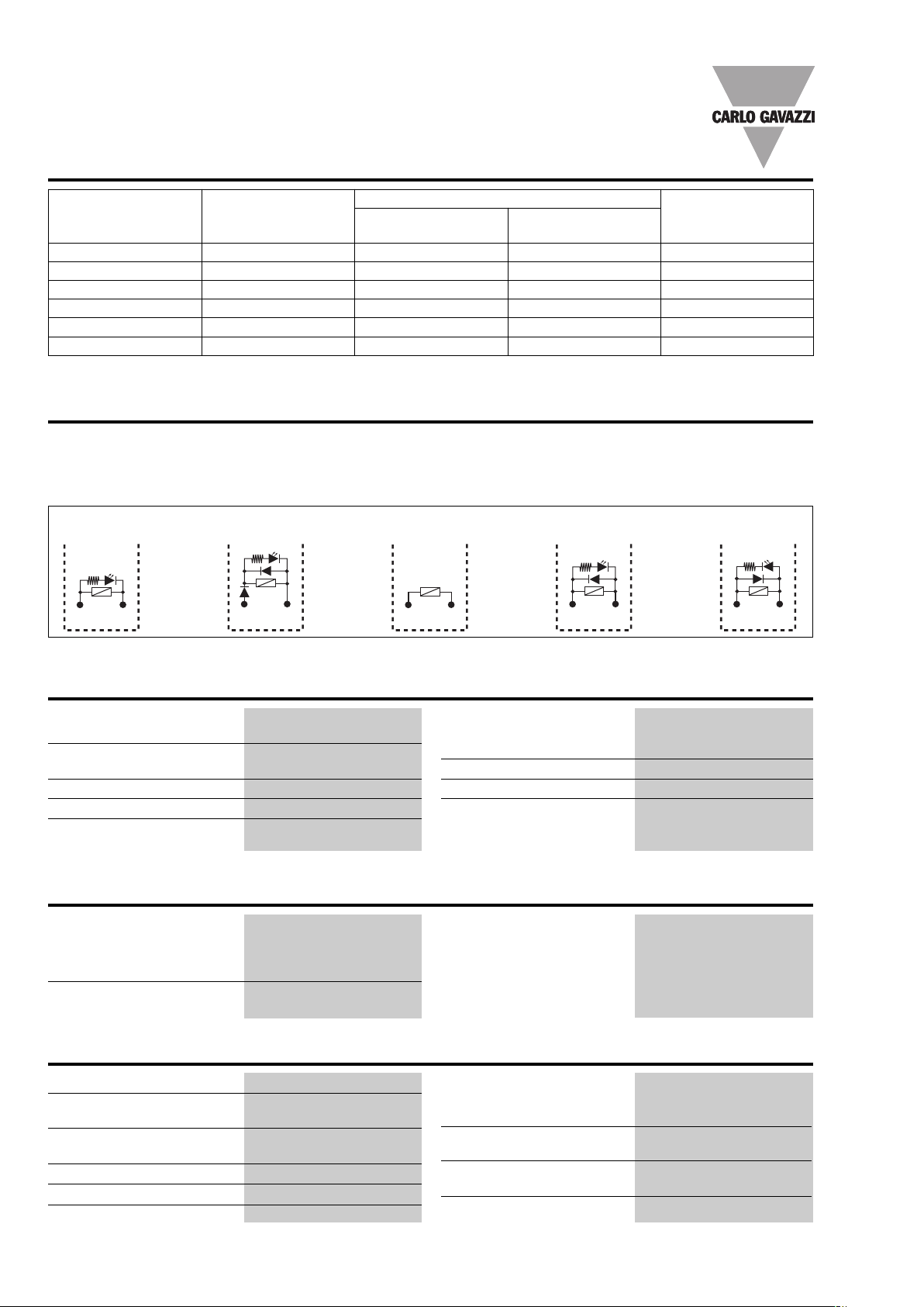
Options
Nil = Standard with Push Arm -LED (A1+) (A2-)- Flag /4 = Plated Contacts Au > 5µm
/0 =
Diode against polarity reverse + free-wheeling Diode (A1+) (A2-)
/1 = Without LED /6 = Free-Wheeling Diode (A1+) (A2-)
/2 = Without Flag /7 = Free-Wheeling Diode (A1-) (A2+)
/3 = Without Push Arm
/5 = Flash Gilded Contacts Au > 1µm
Coil resistance Ω
0.0 ±10%
4
60.0 ±10%
1
50.0 ±10%
6
600.0 ±10%
2
+
1
+
1
A
13
A2
-
14
A
13
2
A
-
14
Contact Characteristics
Contact rating
(with resistive load) 10A - 250VAC / 30VDC
UL rating 10A - 250VAC / 30VDC
1/3HP @ 240VAC
Max. rating 10A - 250VAC / 30VDC
Material AgCe
Initial contact resistance 50mΩ (@ 1A 6VDC)
Insulation
Test Voltage (1 min.)
Between coil and contacts 3750VAC Vr.m.s
Between open contacts 750VAC Vr.m.s
Contact/Contact 1250VA Vr.m.s
Initial insulation resistance 1.000MΩ - 500VAC
1Nil (standard) /6/0 /7
/
A
13
14
2
A
1
+
1
A
3
1
2
A
-
14
Minimum Current
Min. applicable load 5mA @ 12VDC
/4 and /5 versions 1mA @ 6VDC
Max. switch. voltage 250VAC / 30VDC @ 10A
Max. switch. power 2500VA / 300W @ 10A
Life
5
Electrical life 1x10
Mechanical life 1x10
cycles (1800 Ops/h)
7
cycles (1800 Ops/h)
Insulation
according to EN61810-5
Rated insulation voltage 250V
Impulsive insulation voltage 3.6kV
Pollution degree 2
Overvoltage category III
-
1
A
13
2
A
+
14
General Data
Nominal coil power 0.9W DC / 1.2VA AC
Operating time
(At nominal voltage) 20ms max.
Release time
(At nominal voltage) 20ms max.
Ambient temperature
-55° to +70°C (-67° to +158°F)
Vibration resistance 10 to 55Hz 1.0mm (0.04”)
Construction Dust cover
2 Specifications are subject to change without notice. Pictures are just an example. For special features and/or customization, please ask to our sales network.
Shock resistance
Functional 100m/s
2
/10g 11ms
Destructive 1000m/s2/100g
Humidity 35% to 95%
RH non-condensing
Terminals PCB or Soldering Lugs
(Plug-in)
Weight ~37g (~1.30oz)
Page 3

Midi Industrial Relay
Type RMI. 2-10 10A
onostable
M
Pin View mm/inches
R
.3/
6
0.24”
PCB drilling pattern
Dimensions m
m/inches
4.5/0.17”
Diagrams
MI . 2-10 . . .
.3/
.4/
6
6
0.24”
0.25”
0.16”
Wiring Diagram
Ø1.3/0.05
.1/
4
13.2/
0.51”
RMI . 2-10 . . .
28/1.10” 36/1.42”
21.5/0.85”
Soldering Terminals
MI A
R
MI . 2-10 . . .
R
3
1
A1
14
A2
5
9
14
11
8
12
44
41
BOTTOM VIEW
5.8/
0.23”
CB Terminals
P
RMI B
1
12
4
42
4/0.16”
2.2/0.09”x 0.5/0.02”
1/0.04” x 0.5/0.02”
3.5/0.15”
1 Coil Operating Range
2.2
2.0
1.8
1.6
1.4
1.2
UB / UN
1.0
0.8
0.6
0 +10 +20 +30 +40 +50 +60 +70 +80
(32) (+50) (+68) (+86) (+104) (+122) (+140) (+158) (+176)
Ambient temperature °C (°F)
3 Electrical life
ops)
4
500
100
50
10
DC inductive load
L
30VDC — = 7ms
R
AC inductive load
250VAC COS ϕ = 0.4
2 Max. DC load breaking capacity
300
200
100
60
50
40
30
20
DC voltage (VDC)
10
0.1 0.2 0.3 1 2 10 20
DC Current (A)
ops)
4
500
100
50
10
AC resistive load
250VAC
DC resistive load
30VDC
0
012 345
Switching Current (A) inductive load
Number of operations (X 10
Number of operations (X 10
0
024 6810
Switching Current (A) resistive load
Bases and Sockets
DIN rail sockets codes are ZMI2NA, ZMI4NA, ZMI2SA, ZMI4SA, ZMI2GA, ZMI4GA, ZR08 and ZDM14A details and specifications from page
45 to 49 of industrial relays catalogue.
PCB sockets codes are ZC15/2A, ZC15/4A, ZC15/2 and ZC15/4 details and specifications on page 51 of industrial relays catalogue.
Specifications are subject to change without notice. Pictures are just an example. For special features and/or customization, please ask to our sales network 3
 Loading...