

Page 1

DR4500A Truline Circular Chart
Recorder With or Without Control
Product Manual
Doc. No.: 44-45-25-30
Release: L
Last Revision Date: 8/02
Industrial Measurement and Control
Page 2

WARRANTY/REMEDY
Honeywell warrants goods of its manufacture as being free of defective materials and faulty
workmanship. Contact your local sales office for warranty information. If warranted goods are
returned to Honeywell during the period of coverage, Honeywell will repair or replace without
charge those items it finds defective. The foregoing is Buyer's sole remedy and is in lieu of all other
warranties, expressed or implied, including those of merchantability and fitness for a particular
purpose. Specifications may change without notice. The information we supply is believed to be
accurate and reliable as of this printing. However, we assume no responsibility for its use.
While we provide application assistance personally, through our literature and the Honeywell web
site, it is up to the customer to determine the suitability of the product in the application.
Notices and Trademarks
Copyright 2002 by Honeywell
Release L - August, 2002
Industrial Measurement and Control
Honeywell
1100 Virginia Drive
Ft. Washington, PA 19034
DR4500 Truline is a U.S. registered trademark of Honeywell.
Other brand or product names are trademarks of their respective owners.
ii DR4500A Truline Circular Chart Recorder With or Without Control Product Manual Release L
8/02
Page 3

About This Document
References
The following list identifies all documents that may be sources of reference for material discussed in this
publication.
Document Title Doc ID
How to Apply Digital Instrumentation in Severe Electrical
Noise Environments
Modbus® RTU Serial Communications User Manual 51-52-25-66
Modbus® RTU Serial Communications User Manual
Configuration Interface for DR4500
51-52-05-01
51-52-25-69
Contacts
World Wide Web
The following lists Honeywell’s World Wide Web sites that will be of interest to our customers.
Honeywell Organization WWW Address (URL)
Corporate
Industrial Measurement and Control
Telephone
Contact us by telephone at the numbers listed below.
Organization Phone Number
http://www.honeywell.com
http://www.honeywell.com/imc/
United States and Canada Honeywell
Release L DR4500A Truline Circular Chart Recorder With or Without Control Product Manual iii
8/02
1-800-423-9883 Tech. Support
1-888-423-9883 Q&A Faxback
(TACFACS)
1-800-525-7439 Service
Page 4
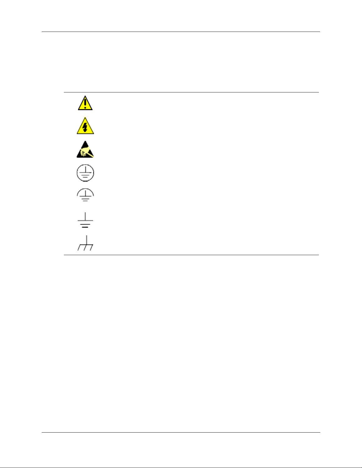
Symbol Definitions
The following table lists those symbols used in this document to denote certain conditions.
Symbol Definition
This CAUTION symbol on the equipment refers the user to the Product Manual for
additional information. This symbol appears next to required information in the manual.
WARNING: risk of electrical shock. This symbol warns the user of a potential shock
hazard where HAZARDOUS LIVE voltages greater than 30 Vrms, 42.4 Vpeak, or 60
VDC may be accessible.
ATTENTION, Electrostatic Discharge (ESD) hazards. Observe precautions for
handling electrostatic sensitive devices
Protective Earth (PE) terminal. Provided for connection of the protective earth (green
or green/yellow) supply system conductor.
Functional earth terminal. Used for non-safety purposes such as noise immunity
improvement. NOTE: This connection shall be bonded to protective earth at the
source of supply in accordance with national local electrical code requirements.
Earth Ground. Functional earth connection. NOTE: This connection shall be bonded to
Protective earth at the source of supply in accordance with national and local electrical
code requirements.
Chassis Ground. Identifies a connection to the chassis or frame of the equipment shall
be bonded to Protective Earth at the source of supply in accordance with national and
local electrical code requirements.
iv DR4500A Truline Circular Chart Recorder With or Without Control Product Manual Release L
8/02
Page 5

Contents
1. Overview ........................................................................................... 1
1.1 Introduction ........................................................................................................1
1.2 Operator Interface..............................................................................................3
1.3 Set-up Tasks......................................................................................................5
2. Installation ......................................................................................... 7
2.1 Overview............................................................................................................7
2.2 Model Number Interpretation...........................................................................13
2.3 Mounting Considerations and Overall Dimensions .........................................16
2.4 Mounting Methods ...........................................................................................17
2.5 Wiring Prerequisites.........................................................................................27
2.6 Input Wiring Procedures ..................................................................................29
2.7 Output Wiring Procedures ...............................................................................39
2.8 Option Wiring Procedures ...............................................................................45
2.9 Lockout Switch Configuration ..........................................................................54
3. Configuration................................................................................... 55
3.1 Overview..........................................................................................................55
3.2 Configuration Prompts.....................................................................................57
3.3 How To Get Started.........................................................................................60
3.4 Configuration Tips............................................................................................61
3.5 Configuration Procedure..................................................................................62
3.6 Input Set Up Group..........................................................................................64
3.7 Pen Set Up Group ...........................................................................................66
3.8 Chart Set Up Group.........................................................................................67
3.9 Time Set Up Group..........................................................................................69
3.10 Totalizer Set Up Group ....................................................................................70
3.11 Input Algorithm Set Up Group .........................................................................72
3.12 Control Set Up Group ......................................................................................73
3.13 Tuning Parameters Set Up Group ...................................................................75
3.14 SP Ramp Set Up Groups ................................................................................76
Release L DR4500A Truline Circular Chart Recorder With or Without Control Product Manual v
8/02
Page 6

3.15 Timer Set Up Group ........................................................................................77
3.16 Alarms Set Up Group ......................................................................................78
3.17 Auxiliary Output Set Up Group ........................................................................80
3.18 Modbus Communications Set Up Group .........................................................81
3.19 Options Set Up Group .....................................................................................82
3.20 Event Message Configuration .........................................................................83
3.21 Lockout Set Up Group .....................................................................................86
3.22 Adjust Printing..................................................................................................87
3.23 Configuration Record Sheet ............................................................................88
4. Configuration Parameter Definitions................................................ 93
4.1 Overview..........................................................................................................93
4.2 Input Parameters Set Up Group ......................................................................94
4.3 Pen Parameters Set Up Group........................................................................98
4.4 Chart Parameters Set Up Group ...................................................................100
4.5 Time Parameters Set Up Group....................................................................103
4.6 Total Parameters Set Up Group....................................................................104
4.7 Input Algorithm Set Up Group .......................................................................106
4.8 Control Parameters Set Up Group ................................................................109
4.9 Tuning Parameters Set Up Group .................................................................119
4.10 Setpoint Ramp Set Up Group........................................................................122
4.11 Timer Set Up Group ......................................................................................124
4.12 Alarms Set Up Group ....................................................................................125
4.13 Auxiliary Output Set Up Group ......................................................................128
4.14 Modbus Communications Set Up Group .......................................................130
4.15 Options Set Up Group ...................................................................................131
4.16 Event Message Set Up Group.......................................................................133
4.17 Lockout Parameters Set Up Group ...............................................................134
4.18 Printing Characteristics Adjustments.............................................................135
5. Operation ...................................................................................... 137
5.1 Overview........................................................................................................137
5.2 Start-up ..........................................................................................................138
5.3 Monitoring Your Recorder .............................................................................142
5.4 Operator Functions........................................................................................148
5.5 Operating Modes ...........................................................................................149
5.6 Setpoints........................................................................................................151
vi DR4500A Truline Circular Chart Recorder With or Without Control Product Manual Release L
8/02
Page 7

5.7 Single Setpoint Ramp....................................................................................153
5.8 Using Two Sets of Tuning Constants (PID Values).......................................156
5.9 Using Accutune II...........................................................................................159
5.10 Alarm Setpoints .............................................................................................162
5.11 Three Position Step Control Algorithm ..........................................................163
5.12 Digital Input Option (Remote Switching)........................................................164
5.13 Resetting and Displaying Totalizer Value......................................................165
5.14 Monitoring the External Event Operation ......................................................167
5.15 Maximizing Pen Life.......................................................................................168
5.16 Routine Maintenance.....................................................................................169
5.17 Installing/Replacing Chart..............................................................................170
5.18 Chart Operation .............................................................................................171
6. Setpoint Ramp/Soak Programming and Operation .......................173
6.1 Overview........................................................................................................173
6.2 Setpoint Program Contents ...........................................................................175
6.3 Drawing a Ramp/Soak Profile .......................................................................178
6.4 Entering the Setpoint Program Data..............................................................183
6.5 SP RAMP1 and SP RAMP2 Set Up Group ...................................................185
6.6 Setpoint Program Profiles Set Up Group ......................................................187
6.7 Setpoint Program Segments Set Up Group ..................................................189
6.8 Setpoint Program Event Set Up Group .........................................................192
6.9 Run/Monitor the Program ..............................................................................196
7. Input Calibration ............................................................................ 199
7.1 Overview........................................................................................................199
7.2 Restoring Factory Calibration ........................................................................200
7.3 Minimum and Maximum Range Values.........................................................202
7.4 Preliminary Information..................................................................................203
7.5 Calibration Set Up and Wiring for PV Inputs .................................................205
7.6 Calibration Procedure....................................................................................214
7.7 Printing Characteristics Adjustments.............................................................217
8. Output Calibration .........................................................................219
8.1 Overview........................................................................................................219
8.2 Current Proportional Output/Aux Out 2 and 3 Calibration.............................220
8.3 Position Proportional and Three Position Step Output Calibration ..............222
Release L DR4500A Truline Circular Chart Recorder With or Without Control Product Manual vii
8/02
Page 8

8.4 Auxiliary Output Calibration ...........................................................................225
9. Troubleshooting / Service.............................................................. 227
9.1 Overview........................................................................................................227
9.2 Troubleshooting Aids.....................................................................................229
9.3 Self Diagnostics.............................................................................................231
9.4 Visual Failure Symptoms...............................................................................237
9.5 Troubleshooting Procedures .........................................................................238
10. Parts List .................................................................................... 245
10.1 Overview........................................................................................................245
10.2 Exploded Views .............................................................................................246
10.3 Miscellaneous Hardware Kit Contents ..........................................................252
10.4 Internal Cabling Data .....................................................................................253
10.5 Internal Wiring Diagram – Options Only........................................................254
A. Model DR45AR .............................................................................255
A.1 Overview........................................................................................................255
A.2 Hardware Identification..................................................................................256
A.3 Fo Reset Configuration..................................................................................258
A.4 Options Configuration....................................................................................259
A.5 Operations Additions .....................................................................................261
A.6 Configuration Worksheet Additions ...............................................................262
B. Security Lockout............................................................................ 263
B.1 Overview........................................................................................................263
C. Foreign Language Safety Instructions........................................... 265
DA2I-6056 ................................................................................................................266
DU2I-6056 ................................................................................................................267
FI2I-6056 ..................................................................................................................268
FR2I-6056.................................................................................................................269
GE2I-6056 ................................................................................................................270
GR2I-6056 ................................................................................................................271
IT2I-6056 ..................................................................................................................272
NO2I-6056 ................................................................................................................273
PO2I-6056 ................................................................................................................274
viii DR4500A Truline Circular Chart Recorder With or Without Control Product Manual Release L
8/02
Page 9

SP2I-6056.................................................................................................................275
SW2I-6056................................................................................................................276
Index ...................................................................................................277
Release L DR4500A Truline Circular Chart Recorder With or Without Control Product Manual ix
8/02
Page 10

Tables
Table 1-1 Function of Keys .........................................................................................................................................4
Table 2-1 Operating Limits and Condensed Specifications.........................................................................................8
Table 2-2 Procedure to Access Components .............................................................................................................14
Table 2-3 Mounting Flush in a New Panel Cutout ....................................................................................................18
Table 2-4 Reference Data for Mounting DR4500A in Existing Panel Cutouts ......................................................... 19
Table 2-5 Mounting Flush in a Panel Using Universal Filler Kit.............................................................................. 20
Table 2-6 Mounting Flush in a Panel Using Kent Model 105M Cutout....................................................................21
Table 2-7 Procedure for Mounting Recorder with Heavy Duty Door .......................................................................22
Table 2-8 Pipe Mounting Procedure..........................................................................................................................24
Table 2-9 Mounting Flush on a Surface (of Panel or Wall).......................................................................................25
Table 2-10 Permissible Wiring Bundling..................................................................................................................28
Table 2-11 AC Line Power Wiring............................................................................................................................31
Table 2-12 Thermocouple, RTD, Radiamatic, mV, or 0–5 Vdc Input Wiring ..........................................................33
Table 2-13 4-20 mA Input Wiring............................................................................................................................. 35
Table 2-14 0-10 Volt dc Input Wiring.......................................................................................................................37
Table 2-15 4-20 mA Control Output Wiring.............................................................................................................39
Table 2-16 Position Proportional Control Output Wiring .........................................................................................41
Table 2-17 Relay Control Output Wiring..................................................................................................................43
Table 2-18 Alarm Output or Digital Input Wiring.....................................................................................................45
Table 2-19 Alarm 3 and Alarm 4 Output Wiring ......................................................................................................47
Table 2-20 Alarm 5 and Alarm 6 Output Wiring ......................................................................................................48
Table 2-21 RS485 Modbus Communications Wiring................................................................................................50
Table 2-22 4-20 mA Auxiliary Output Wiring..........................................................................................................52
Table 3-1 Configuration Tips ....................................................................................................................................61
Table 3-2 Configuration Procedure ........................................................................................................................... 62
Table 3-3 Input Group Function Prompts.................................................................................................................. 64
Table 3-4 Pen 1, 2, 3, 4 Group Function Prompts .....................................................................................................66
Table 3-5 Chart Group Function Prompts .................................................................................................................67
Table 3-6 Time Group Function Prompts ..................................................................................................................69
Table 3-7 Totalizer Group Function Prompts............................................................................................................ 70
Table 3-8 Input Algorithm Group Function Prompts ................................................................................................72
Table 3-9 Control 1 or Control 2 Group Function Prompts.......................................................................................73
Table 3-10 Tuning 1 or Tuning 2 Group Function Prompts ......................................................................................75
Table 3-11 SP Ramp 1 or 2 Group Function Prompts...............................................................................................76
Table 3-12 Timer Group Function Prompts...............................................................................................................77
Table 3-13 Priority of functions that operate relays ..................................................................................................78
Table 3-14 Alarms Group Function Prompts............................................................................................................. 79
Table 3-15 Auxiliary Output Group Function Prompts.............................................................................................80
Table 3-16 Modbus Communications Group Function Prompts ...............................................................................81
Table 3-17 Options Group Function Prompts............................................................................................................82
Table 3-18 Event Message Group Function Prompts................................................................................................83
Table 3-19 Lockout Group Function Prompts...........................................................................................................86
Table 3-20 Adjust Group Function Prompts..............................................................................................................87
Table 4-1 Input Group Definitions ............................................................................................................................ 94
Table 4-2 Pen 1, 2, 3, or 4 Group Definitions............................................................................................................98
Table 4-3 Chart Parameters Group Definitions ....................................................................................................... 100
Table 4-4 Time Parameters Group Definitions........................................................................................................103
Table 4-5 Totalizer Group Definitions ....................................................................................................................104
Table 4-6 Input Algorithm Group Definitions ......................................................................................................... 106
Table 4-7 Control 1 or 2 Group Definitions ............................................................................................................109
Table 4-8 Tuning Group Prompt Definitions...........................................................................................................119
Table 4-9 Setpoint Ramp 1 or 2 Group Definitions.................................................................................................122
Table 4-10 Timer Group Definitions....................................................................................................................... 124
x DR4500A Truline Circular Chart Recorder With or Without Control Product Manual Release L
8/02
Page 11

Table 4-11 Priority of functions that operate relays .................................................................................................125
Table 4-12 Alarms Group Definitions..................................................................................................................... 126
Table 4-13 Auxiliary Output Group Definitions .....................................................................................................128
Table 4-14 Modbus Communications Group Definitions........................................................................................130
Table 4-15 Option Group Definitions......................................................................................................................131
Table 4-16 Event Message Group Definitions.........................................................................................................133
Table 4-17 Lockout Group Definitions ................................................................................................................... 134
Table 4-18 Printing Characteristics Adjustment Procedure.....................................................................................136
Table 5-1 Power Up Diagnostic Tests..................................................................................................................... 138
Table 5-2 Procedure for Testing the Displays and Keys .........................................................................................139
Table 5-3 Procedure for Starting Up the Recorder ..................................................................................................140
Table 5-4 Meaning of Indicators .............................................................................................................................143
Table 5-5 Lower Display Key Parameter Prompts..................................................................................................145
Table 5-6 Error Messages........................................................................................................................................ 146
Table 5-7 Alarm and tuning messages.....................................................................................................................147
Table 5-8 Operating Mode Definitions....................................................................................................................149
Table 5-9 Changing Operating Modes.....................................................................................................................149
Table 5-10 Procedure for Selecting Automatic or Manual Mode............................................................................150
Table 5-11 Procedure for Selecting the Setpoint Source .........................................................................................151
Table 5-12 Procedure for Changing the Local Setpoint ..........................................................................................151
Table 5-13 Procedure for Switching Between Setpoints .........................................................................................152
Table 5-14 Setpoint Selection Indication.................................................................................................................152
Table 5-15 Procedure for Configuring a Single Setpoint Ramp ..............................................................................153
Table 5-16 Procedure for Running a Setpoint Ramp ...............................................................................................154
Table 5-17 Procedure for Selecting Two Sets of Tuning Constants ........................................................................156
Table 5-18 Procedure for Setting Switchover Values..............................................................................................157
Table 5-19 Procedure for Setting Tuning Constant Values.....................................................................................157
Table 5-20 Procedure for Switching PID Sets from the Keyboard..........................................................................158
Table 5-21 Procedure for Starting Accutune II........................................................................................................159
Table 5-22 Procedure for Using Accutune for Duplex Control...............................................................................160
Table 5-23 Procedure for Displaying or Changing the Alarm Setpoints .................................................................162
Table 5-24 Procedure for Displaying the 3PSTEP Motor Position .........................................................................163
Table 5-25 Digital Input Option Action on Contact Closure...................................................................................164
Table 5-26 Procedure for Resetting the Totalizer....................................................................................................165
Table 5-27 Procedure for Displaying the Totalizer Value.......................................................................................166
Table 5-28 Maximizing Pen Life.............................................................................................................................168
Table 5-29 Cleaning the Pen Tip.............................................................................................................................169
Table 5-30 Replacing a Chart Lamp........................................................................................................................169
Table 5-31 Installing/Replacing the Chart...............................................................................................................170
Table 5-32 Remote Chart Modes.............................................................................................................................172
Table 6-1 Parameter settings for example 12-step profile .......................................................................................179
Table 6-2 Setpoint program data entry procedure ...................................................................................................183
Table 6-3 SP RAMP prompts and available selections ...........................................................................................185
Table 6-4 Setpoint Program Profiles Group Definitions .........................................................................................187
Table 6-5 Setpoint Program Segments Group Definitions ......................................................................................189
Table 6-6 Setpoint Program Event Group Definitions.............................................................................................192
Table 6-7 Segment Event relay operation requirements ..........................................................................................193
Table 6-8 Run/Monitor Functions ........................................................................................................................... 196
Table 7-1 Restoring Factory Calibration .................................................................................................................200
Table 7-2 Voltage and Resistance Equivalents for 0 % and 100 % Range Values..................................................202
Table 7-3 Disconnect the Field Wiring....................................................................................................................203
Table 7-4 Equipment Needed..................................................................................................................................204
Table 7-5 General Set Up Procedure ....................................................................................................................... 206
Table 7-6 Set Up Wiring Procedure for Thermocouple Inputs Using an Ice Bath ..................................................207
Table 7-7 Set Up Wiring Procedure for Thermocouple Inputs Using a Compensated Calibrator Method..............208
Release L DR4500A Truline Circular Chart Recorder With or Without Control Product Manual xi
8/02
Page 12

Table 7-8 Set Up Wiring Procedure for Thermocouple Inputs Using the Ambient Temperature Method.............. 209
Table 7-9 Set Up Wiring Procedure for RTD Inputs...............................................................................................210
Table 7-10 Set Up Wiring Procedure for Radiamatic, Millivolts, and Volts Inputs (except 0-10 Volts) ................211
Table 7-11 Set Up Wiring Procedure for 0–10 Volt Inputs .....................................................................................212
Table 7-12 Set Up Wiring Procedure for 4–20 mA Inputs ......................................................................................213
Table 7-13 Calibration Procedure Sequence............................................................................................................214
Table 8-1 Set Up Wiring Procedure Current Proportional Output/Aux Out 2 and 3...............................................220
Table 8-2 Current Proportional Output/Aux Output 2 and 3 Calibration Procedure ............................................... 221
Table 8-3 Position Proportional and 3 Position Step Output Calibration Procedure ...............................................223
Table 8-4 Set Up Wiring Procedure Auxiliary Output ............................................................................................225
Table 8-5 Auxiliary Output Calibration Procedure..................................................................................................226
Table 9-1 Identifying the software version.............................................................................................................. 230
Table 9-2 Power-up tests .........................................................................................................................................231
Table 9-3 Displaying the test results........................................................................................................................232
Table 9-4 Error message prompts............................................................................................................................233
Table 9-5 Visual failure symptoms..........................................................................................................................237
Table 9-6 Procedure #1—Troubleshooting recorder failure symptoms...................................................................238
Table 9-7 Procedure #2—Troubleshooting pen trace failure symptoms .................................................................239
Table 9-8 Procedure #3—Troubleshooting chart rotation failure symptoms...........................................................239
Table 9-9 Procedure #4—Troubleshooting chart rotation failure symptoms...........................................................240
Table 9-10 Procedure #5—Troubleshooting pen failure symptoms........................................................................240
Table 9-11 Procedure #6—Troubleshooting keyboard and/or display failure symptoms .......................................240
Table 9-12 Procedure #7—Troubleshooting current proportional output failure symptoms...................................241
Table 9-13 Procedure #8—Troubleshooting position proportional output failure symptoms .................................241
Table 9-14 Procedure #9—Troubleshooting relay output failure symptoms...........................................................242
Table 9-15 Procedure #10—Troubleshooting current/time or time/current failure symptoms ................................ 242
Table 9-16 Procedure #11—Troubleshooting the auxiliary output .........................................................................243
Table 9-17 Procedure #12—Troubleshooting external alarm function failure symptoms.......................................243
Table 9-18 Procedure #13—Troubleshooting Modbus communications ................................................................243
Table 10-1 Door assembly parts..............................................................................................................................246
Table 10-2 Chart plate assembly parts.....................................................................................................................247
Table 10-3 Basic recorder parts without options ..................................................................................................... 249
Table 10-4 Recorder parts associated with options .................................................................................................251
Table 10-5 Miscellaneous hardware kit...................................................................................................................252
Table A-1 Fo RESET group function prompts........................................................................................................258
Table A-2 Options group function prompts, continued from Section 3/Table 3-17 ................................................259
Table A-3 Option group definitions, continued from Section 4/Table 4-15............................................................ 260
xii DR4500A Truline Circular Chart Recorder With or Without Control Product Manual Release L
8/02
Page 13

Figures
Figure 1-1 Operator Interface ...................................................................................................................................... 3
Figure 1-2 Set-up Tasks...............................................................................................................................................5
Figure 2-1 Model Number Interpretation ..................................................................................................................13
Figure 2-2 DR4500A Recorder Hardware Components Versus “Table” Selections ................................................. 15
Figure 2-3 Overall Dimensions .................................................................................................................................16
Figure 2-4 How to Remove Knockouts ..................................................................................................................... 17
Figure 2-5 Mounting Flush in a New Panel Cutout ...................................................................................................18
Figure 2-6 Mounting in a Panel Using Universal Filler Kit ......................................................................................20
Figure 2-7 Mounting in a Panel using Kent Model 105M Cutout.............................................................................21
Figure 2-8 Panel Mounting Recorder with Heavy Duty Door...................................................................................23
Figure 2-9 Pipe Mounting Brackets...........................................................................................................................24
Figure 2-10 Mounting Flush on a Surface (of Panel or Wall) ...................................................................................26
Figure 2-11 Ferrite Filter Locations and Shield Wiring (CE Mark)..........................................................................30
Figure 2-12 AC Line Power Wiring ..........................................................................................................................32
Figure 2-13 Thermocouple, RTD, Radiamatic, mV, or 0–5 Vdc Input Wiring.........................................................34
Figure 2-14 4-20 mA Input Wiring............................................................................................................................36
Figure 2-15 0-10 Volt dc Input Wiring...................................................................................................................... 38
Figure 2-16 4-20 mA Control Output Wiring (or Aux Out #2 and #3 Wiring) .........................................................40
Figure 2-17 Position Proportional Control Output or Three Position Step Wiring....................................................42
Figure 2-18 Relay Control Output Wiring................................................................................................................. 44
Figure 2-19 Alarm Output or Digital Input Wiring ...................................................................................................46
Figure 2-20 Alarm outputs #3, 4, 5, and 6 wiring......................................................................................................49
Figure 2-21 RS485 Modbus Communications Wiring .............................................................................................. 51
Figure 2-22 4-20 mA Auxiliary Output #1 Wiring....................................................................................................53
Figure 2-23 S1 Lockout Switch Location..................................................................................................................54
Figure 3-1 DR4500A Prompt Hierarchy ...................................................................................................................57
Figure 5-1 Operator Interface .................................................................................................................................. 142
Figure 5-2 Deviation Bargraph................................................................................................................................144
Figure 6-1 Ramp/Soak Profile Example..................................................................................................................178
Figure 7-1 Location of the Input Connections on the Input Boards ........................................................................ 203
Figure 7-2 Location of Jumper Positions W1/MA and W3 on the Input Boards.....................................................205
Figure 7-3 Calibration Set Up Diagram for Thermocouple Inputs Using an Ice Bath.............................................207
Figure 7-4 Calibration Set Up Diagram for Thermocouple Inputs Using a Compensated Calibrator Method........ 208
Figure 7-5 Calibration Set Up Diagram for Thermocouple Inputs using the Ambient Temperature Method .........209
Figure 7-6 Calibration Set Up Diagram for RTD Inputs .........................................................................................210
Figure 7-7 Calibration Set Up Diagram for Radiamatic, Millivolts, and Volts Inputs (except 0-10 Volts) ............211
Figure 7-8 Calibration Set Up Diagram for 0–10 Volt Inputs .................................................................................212
Figure 7-9 Calibration Set Up Diagram for 4–20 mA Inputs ..................................................................................213
Figure 8-1 Test Equipment Connections for Calibrating Current Proportional Output...........................................220
Figure 8-2 Test Equipment Connections for Calibrating Auxiliary Output.............................................................225
Figure 10-1 Door assembly .....................................................................................................................................246
Figure 10-2 Chart plate assembly ............................................................................................................................ 247
Figure 10-3 Basic recorder components without options ........................................................................................248
Figure 10-4 Recorder components associated with options.....................................................................................250
Figure 10-5 Internal cabling for DR4500A Truline recorder...................................................................................253
Figure 10-6 Internal diagram for DR4500A Truline recorder – options only..........................................................254
Figure A-1 DR45AR with one input........................................................................................................................256
Figure A-2 DR45AR with two to four inputs .......................................................................................................... 257
Release L DR4500A Truline Circular Chart Recorder With or Without Control Product Manual xiii
8/02
Page 14

Page 15

1.1 Introduction
Function
The DR4500A Truline Recorder is a one to four-channel microprocessor-based circular chart recorder. Its
"one-pen" stylus printhead produces up to four analog traces and prints alphanumeric chart data on a blank
heat-sensitive chart. All four traces share the same time line reference which the Truline prints. This
eliminates the error caused by pen alignment offsets in conventional pen designs. Since the Truline prints
the chart and generates the analog traces at the same time, there is no error due to variations in chart size
caused by changes in temperature and humidity.
In addition to printing chart records, the Truline recorder alternately displays process variable values for all
channels in the selected engineering units.
Models with up to four input channels accept inputs from any one of a variety of sensors or transmitters
within the configurable range limits.
The Truline is also available with one or two independent digital controllers and setpoint programmers.
CE Conformity (Europe)
Indicated models of this product are in conformity with the protection requirements of the following
European Council Directives: 73/23/EEC, the Low Voltage Directive, and 89/336/EEC, the EMC
Directive. Conformity of this product with any other “CE Mark” Directive(s) shall not be assumed.
1. Overview
Deviation from the installation conditions specified in this manual, and the special conditions for CE
conformity in Subsection 2.1, may invalidate this product’s conformity with the Low Voltage and EMC
Directives.
ATTENTION
The emission limits of EN 61326 are designed to provide reasonable protection against
harmful interference when this equipment is operated in an industrial environment. Operation
of this equipment in a residential area may cause harmful interference. This equipment
generates, uses, and can radiate radio frequency energy and may cause interference to radio
and television reception when the equipment is used closer than 30 meters (98 feet) to the
antenna(e). In special cases, when highly susceptible apparatus is used in close proximity, the
user may have to employ additional mitigating measures to further reduce the electromagnetic
emissions of this equipment.
Microprocessor controlled recording and printing
Both the chart and printhead are driven by stepper motors controlled by the microprocessor with
configurable chart speed through the keypad.
You can configure various "printed" chart data such as range marking in engineering units, digital values
for process variables, and trace identification. This data plus printed time lines and engineering units of
scale eliminate the need to maintain an inventory of a variety of preprinted charts.
The Truline recorder uses a dot fill technique from a microprocessor algorithm to produce a continuous
analog trace of a process variable.
Release L DR4500A Truline Circular Chart Recorder With or Without Control Product Manual
8/02
1
Page 16

Overview
Introduction
Digital controller
The DR4500A recorder controller includes an integral microprocessor-based, single or dual loop PID
controller with optional setpoint program. A variety of output types, including a duplex variation for heat
cool applications, lets you select the output that is right for your final control element. Accutune II lets you
automatically tune your loops.
You can configure the control action as On-Off, PID-A, PID-B, PD with manual reset, or Three Position
Step. English language prompts guide you through the entry of all the controller's configurable parameters.
Construction
The DR4500A recorder is housed in a molded case which can be panel or surface mounted. A glass or
acrylic windowed door (A UL and FM approved NEMA4X door is also available )protects the internal
components while allowing easy access to the chart and operator interface. An optional external keypad
that allows operator selections without opening the door is available.
Circuitry is partitioned on printed circuit boards for ease of service.
Power, input, and output wiring connect to terminations inside the case. Knockouts in the sides and bottom
of the case accept conduit connections for convenient wire entry.
2 DR4500A Truline Circular Chart Recorder With or Without Control Product Manual Release L
8/02
Page 17
1.2 Operator Interface
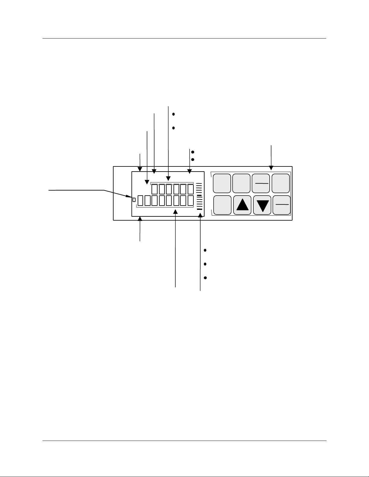
Operator interface
Figure 1-1 shows the operator interface and defines the displays and indicators. The function of the keys is
described in Table 1-1.
Indicates temperature units of PV Upper Display - six characters
PV displayed is for channel
1, 2, 3, or 4
Alarm condition exists for
alarm 1 or 2, when lit.
ALM
CHN
Remote set point or
2nd set point is active,
when lit. Blinks when
2nd setpoint or remote
setpoint is attained
through remote switch
RSP
OUT
12 FC
1234
12
Operator Interface
Normal operation - Displays process
variable (PV) for selected channels.
Configuration mode - Displays selection or
parameter value.
Indicates controller mode:
MAN = Manual
Keypad /
Key functions
A = Automatic
MAN
FUNC
LOWR
DISP
MAN
AUTO
CHART
%
SET
UP
RUN
HOLD
Overview
Control relay 1 or 2 is
ON, when lit.
Lower Display - eight characters
• Normal operation - Displays selectable
operating parameters and values. Indicates
diagnostic error messages, alarm condition
for alarms 3-6, Accutune in progress.
• Configuration mode - Displays function
group and parameters.
Bargraph - deviation (±10% of span)
Center green bar indicates PV is within
±1% of control setpoint
Next small bar will light if PV is between
±1% but less than ±2% in deviation.
If PV is equal to or greater than ±10%
deviation, the green bar plus all ten small
green bars will light.
Figure 1-1 Operator Interface
.
Release L DR4500A Truline Circular Chart Recorder With or Without Control Product Manual 3
8/02
Page 18
Overview
Operator Interface
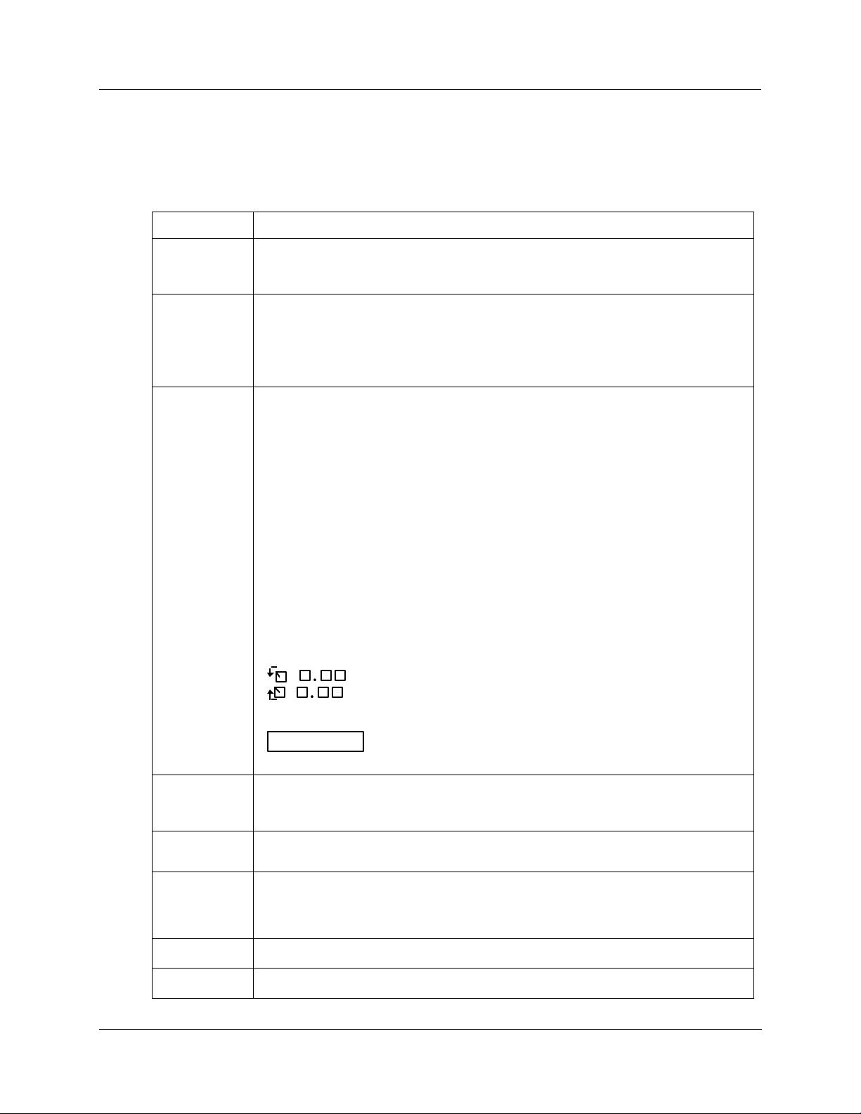
Key functions
Table 1-1 shows each key on the operator interface and defines its function.
Key Function
Table 1-1 Function of Keys
SET
UP
FUNC
LOWR
DISP
• Places the controller in the Configuration Set Up group select mode. Sequentially
displays Set Up groups and allows the FUNC key to display individual functions in
each Set Up group.
• Used in conjunction with the SET UP key to select the individual functions of a
selected Configuration Set Up group.
• Used to toggle between SP1 and SP2.
• Used during field calibration procedure.
• Selects an operating parameter to be shown in the lower display:
OUT = Output Value (estimated motor position for 3 Position Step)
SP = Local Setpoint 1
SPN = Current setpoint for setpoint rate applications
2SP = Local Setpoint 2
RSP = Remote Setpoint
1IN = Input 1 (if Loop 1 is a derived PV)
2IN = Input 2
3IN = Input 3
4IN = Input 4
DEV = Deviation
EU = PV Engineering Units
RH = % RH Value
PIDSETX = Tuning Parameter Set X=1 or 2
RAMP = Minutes remaining in Setpoint Ramp
#RA = Minutes remaining in SP Prog Ramp
#SK = Minutes remaining in SP Prog Soak
RECYC = Number of recycles left in SP Program
= Time remaining in Timer function
= Time elapsed in Timer function
TUNExXXX = Accutune II indicator. x = 1 or 2
ATTENTION
The lower display can be configured to scroll through the operating
parameters.
MAN
AUTO
• Alternately selects:
AUTO Lower display automatically displays setpoint value in engineering units.
MAN Lower display automatically indicates output in %.
CHART
• Used to stop printing operation and move pen to outer limit for chart change.
Display will revert to date and time.
RUN
• Alternate action switch initiates or holds the Setpoint Ramp or Setpoint Program.
HOLD
• In configuration mode, restores the original value or selection if you do not want to
enter a change you are making to a parameter.
▲
▼
• Increases the setpoint, output, or configuration values displayed.
• Decreases the setpoint, output, or configuration values displayed.
4 DR4500A Truline Circular Chart Recorder With or Without Control Product Manual Release L
8/02
Page 19
1.3 Set-up Tasks
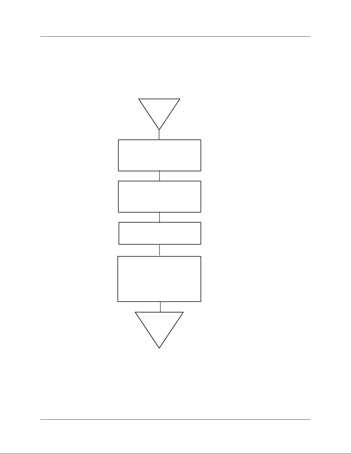
Major set-up tasks
As shown in Figure 1-2, there are four major tasks that you must complete to "Set Up" the DR4500A
recorder for operation. For easy reference the section numbers for each task are shown.
START
1.
Determine your recorder's
hardware components and
software functions
Mount the recorder flush in
2.
a panel, or on the surface
of a panel or a wall
Overview
Set-up Tasks
See Section 2
See Section 2
3.
Connect the power and
input/output wiring.
Follow the simple keystroke
4.
See Section 2
sequences and English
language prompts to
See Sections 3 & 4
"configure" the functional
characteristics of your
recorder.
Ready for
Operation
For Model DR45AR, also see Appendix A
21402
Figure 1-2 Set-up Tasks
Release L DR4500A Truline Circular Chart Recorder With or Without Control Product Manual 5
8/02
Page 20

Overview
Set-up Tasks
6 DR4500A Truline Circular Chart Recorder With or Without Control Product Manual Release L
8/02
Page 21

2.1 Overview
Introduction
Installation of the DR4500A Recorder consists of mounting and wiring the recorder according to the
instructions given in this section.
Read the preinstallation information, check the model number interpretation and become familiar with your
model selections, then proceed with installation.
What’s in this section?
This section contains the following information:
2.1 Overview 7
2.2 Model Number Interpretation 13
2. Installation
Topic See Page
2.3 Mounting Considerations and Overall Dimensions 16
2.4 Mounting Methods 17
2.5 Wiring Prerequisites 27
2.6 Input Wiring Procedures 29
2.7 Output Wiring Procedures 39
2.8 Option Wiring Procedures 45
2.9 Lockout Switch Configuration 54
Pre-installation information
If the recorder has not been removed from its shipping carton, inspect the carton for damage and remove
the recorder. Inspect the unit for any obvious shipping damage and report any damage due to transit to the
carrier.
Make sure a bag containing mounting hardware is included in the carton with the recorder.
Check that the model number shown on the chart plate agrees with what you have ordered.
CE Conformity special conditions (Europe)
Braid shielded twisted pair cables are required for all Analog I/O, Process Variable, RTD, Thermocouple,
dc millivolt, low level signal, 4-20 mA, and relay output circuits. Supplementary bonding of the recorder
enclosure to a local ground, using a 3/4” braided copper conductor, is required. Ferrite suppression filters
and capacitor filters (see Subsection 2.5 for Wiring Prerequisites) shall be installed on all cables connected
to the recorder/controller.
Refer to document 51-52-05-01, How to Apply Digital Instrumentation in Severe Electrical Noise
Environments, for additional installation guidance.
Release L DR4500A Truline Circular Chart Recorder With or Without Control Product Manual 7
8/02
Page 22

Installation
Overview
Operating limits and condensed specifications
We recommend that you review and adhere to the operating limits listed in Table 2-1 when you install your
recorder.
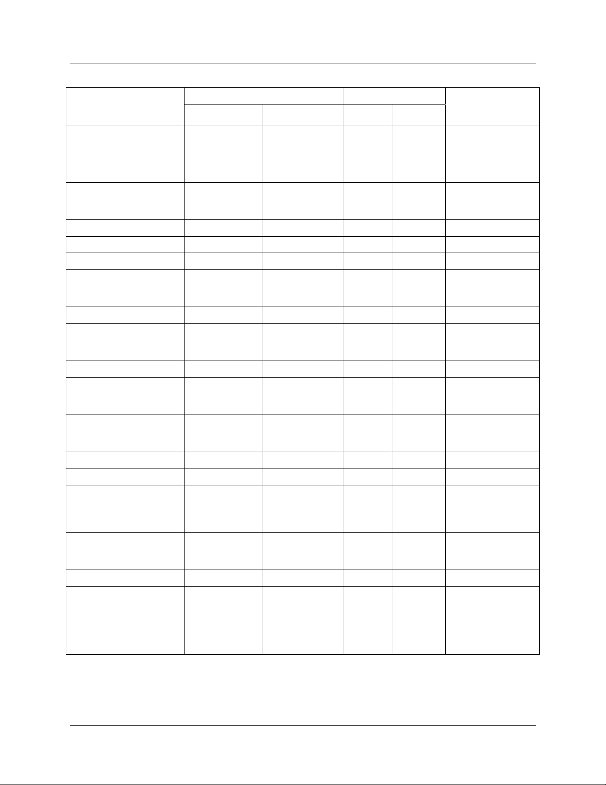
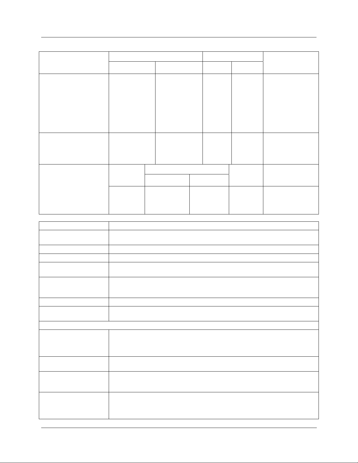
Table 2-1 Operating Limits and Condensed Specifications
Condition Specifications
Ambient Temperature
Relative Humidity
Vibration
Frequency
Acceleration
Mechanical Shock
Acceleration
Duration
Power
Power Consumption
Digital Indication
Accuracy
Minimum Input Span
Input Impedance
Source Impedance
Sampling Rate
Input Filter
Digital Displays
Indicators
Deviation Bargraph
Controller Modes of
Operation
Transmitter Supply
Voltage
32 °F to 131 °F (0 °C to 55 °C)
5 % to 90 % RH at 40 °C (104 °F)
0 to 200 Hz
0.2 g
5 g
30 ms
102 Vac to 132 Vac 50/60 Hz
204 Vac to 264 Vac 50/60 Hz
20 VA maximum
1 digit
Range is fully configurable with span limitation of the operating range selected.
4-20 mA dc: 250 ohms
0-10 Vdc: 200K ohms
All others: 10 Megohms
RTD: 100 ohms per lead maximum
Each input sampled 3 times a second (1 or 2 inputs); 3 times in 2 seconds (3 or 4
inputs).
Software: Single pole low pass section with selectable time constants (off to 120
seconds).
Vacuum fluorescent, alphanumeric.
A six-digit display dedicated to the process variable.
Alternate information displayed during configuration mode.
An eight-digit display shows key selected operating parameters. Also provides
guidance during configuration.
Channel PV display (CHN 1, 2, 3, or 4)
Alarm status (ALM 1, 2)
Controller Output (OUT 1, 2)
Remote Setpoint (RSP)
Temperature unit (F or C) or Engineering Units
Controller’s mode (A or MAN)
21 segment, color coded deviation bargraph:
Green (large) = On Control
Green (small) = Deviation to ± 10 % of PV
Manual Operation
Automatic with local setpoint
Automatic with remote setpoint
22 Vdc to 26 Vdc at input terminals (50 mA dc at 24 Vdc)
8 DR4500A Truline Circular Chart Recorder With or Without Control Product Manual Release L
8/02
Page 23

Condition Specifications
Controller Output1
(Optional)
Auxiliary Output
(Optional)
Installation
Overview
• On-Off or Time Proportional
One SPST electromechanical relay. Control action can be set for direct or reverse;
N.O. or N.C. contact selectable.
• On-Off Duplex or Time Proportional Duplex
Two SPST electromechanical relays. Control action can be set for direct or reverse;
N.O. or N.C. contact selectable.
• Current Proportional
21 mA dc maximum into a negative or positive grounded or non-grounded load of 0
to 1000 ohms. Output range can be set between 4 and 20 mA, and as direct or
reverse action.
Resolution: 10 bits
Accuracy: 0.5 % full scale
FM Approved Output (optional)
• Position Proportional and Three Position Step
Two SPST electromechanical relays operate motor having a 100 ohm to 1000 ohm
slidewire.
• Current/Time Duplex and Time/Current Duplex
Variation of time proportional duplex for Heat/Cool applications. Time proportional
output (heat or cool) is a SPST electromechanical relay. Current proportional output
(heat or cool) is a 4-20 mA signal that can be fed into a negative or positive
grounded load of 0 to 1000 ohms and is operational over 50 % of range or the
entire range.
Time Proportional Relay Resolution: 4.4 mSec
Relay Contact Ratings:
Resistive Load: 5 A @ 120 Vac, 2.5 A @ 240 Vac
Inductive Load: 50 VA @ 120 Vac or 240 Vac
Cycle Time: 1 second to 120 seconds
Current Proportional:
Resolution: 10 bits
Accuracy: 0.5 % full scale
21 mA dc maximum into a negative or positive grounded load of 0 to 1000 ohms. The
range can be set between 0 to 21 mA. It can be configured to represent any one of 12
control parameters.
Resolution: 12 bits over 0 to 21 mA
Accuracy: 0.2 % of full scale
Temperature Stability: 0.03 % F.S./°C
Release L DR4500A Truline Circular Chart Recorder With or Without Control Product Manual 9
8/02
Page 24
Installation
Overview
2
Actuations
Thermocouples3
B
E
E (low)
J
J (low)
K
K (low)
NNM (Ni Ni Moly)
NIC (Nicrosil-Nisil)
R
S
T
T (low)
W5W26
W5W26 (low)
°F °C ± °F ± °C
105 to 3300
105 to 150
150 to 500
500 to 1000
1000 to 3300
–454 to 1832
–454 to –202
–202 to 1832
–200 to 1100 –129 to 593
0 to 1600 –18 to 871
20 to 770 –7 to 410
–320 to 2500
–320 to 0
0 to 2500
–20 to 1000 –29 to 538
32 to 2500
32 to 500
500 to 2500
0 to 2372 –18 to 1300
0 to 3100
0 to 500
500 to 3100
0 to 3100
0 to 500
500 to 3100
–300 to 700 –184 to 371
–200 to 600 –129 to 316
0 to 4200
0 to 600
600 to 3600
3600 to 4200
0 to 2240
0 to 600
600 to 2240
Range Reference Accuracy Types of Input
41 to 1816
41 to 66
66 to 260
260 to 538
538 to 1815
–270 to 1000
–270 to –130
–130 to 1000
–196 to 1371
–196 to –18
–18 to 1371
0 to 1371
0 to 260
260 to 1371
–18 to 1704
–18 to 260
260 to 1704
–18 to 1704
–18 to 260
260 to 1704
–18 to 2315
–18 to 316
316 to 1982
1982 to 2315
–18 to 1227
–18 to 316
316 to 1227
Radiamatic 1400 to 3400 760 to 1871
RTD
Platinum
100 ohms
200 ohms (high)5
200 ohms (low)
5
500 ohms
–300 to 900
32 to 752
32 to 392
–300 to 900
–184 to 482
0 to 400
0 to 200
–184 to 482
Temp Stability ±
Degrees Error Per 1
Degree ∆T
42.00
14.00
3.00
1.50
18.00
1.00
23.00
7.70
1.70
0.80
10.00
0.55
2.00
2.00
0.50
0.20
0.70
0.35
0.50 0.30 0.20
0.40 0.22 0.06
0.20 0.11 0.04
1.25
0.60
0.70
0.35
0.18
0.09
0.30 0.16 0.05
0.75
0.50
0.40
0.30
0.09
0.07
1.0 0.55 0.01
2.00
1.00
2.00
1.00
1.10
0.55
1.10
0.55
0.25
0.13
0.23
0.13
0.60 0.35 0.07
0.40 0.22 0.07
1.40
1.30
1.60
1.10
1.00
0.77
0.70
0.90
0.60
0.55
0.17
0.17
0.29
0.14
0.10
1.00 0.55 0.10
0.40
0.30
0.20
0.20
0.22
0.16
0.12
0.11
0.05
0.05
0.05
0.05
10 DR4500A Truline Circular Chart Recorder With or Without Control Product Manual Release L
8/02
Page 25
Installation
Overview
2
Actuations
Linear
Milliamperes dc
Millivolts dc
Volts dc
Relative Humidity
Platinum 100 ohm
Wet/Dry Bulb*
Wet/Dry Input
% RH4
Range Reference Accuracy Types of Input
°F °C ± °F ± °C
4 to 20
0 to 10
10 to 50
1 to 5 (can be
calibrated
0 to 5)
0 to 10
–130 to 392
—
—
—
—
–90 to 200
0.10 %
0.05 %
0.05 %
0.05 %
0.10 %
0.30
Dry Bulb Range Measured
% RH
0 to <20
20 to 100
°F °C
–103 to 212
35 to 40
>40 to 100
100 to 212
–75 to 100
2 to 4
>4 to 38
38 to 100
—
—
—
—
0.03
Reference
Accuracy
2 % RH
2 % RH
1 % RH
1 % RH
Temp Stability ±
Degrees Error Per 1
Degree ∆T
0.004 %/°F
0.004 %/°F
0.004 %/°F
0.004 %/°F
0.004 %/°F
0.03
Temp. Stability
53 °F to 104 °F/
12 °C to 40 °C
0.11 % RH/°F
0.11 %RH/°F
0.06 % RH/°F
0.03 % RH/°F
Condition Specifications
Case Molded, foamed-Noryl** with gasketed door.
A UL and FM approved NEMA4X door is also available.
Chart
Wiring Connections
12-inch (304.8 mm) diameter chart. Plain thermal-sensitive paper.
Terminals inside the case.
Color Case: Black
Door (standard): Caribbean Blue, Black, or Gray
Approval Bodies U.L. Approval depending on model. CSA Approval. Consult Model Selection Guide for
information.
FM approved for Class I, Div. 2, Groups A, B, C, D areas depending on model.
Weight
13.2 lbs (6 kg)
Mounting Panel, 2-inch pipe, or surface mounted. Some adapter kits available for existing panel
cutouts.
OPTIONS
Alarm Output Two, four, or six relays available.
Relay Contact Ratings:
First Relays, Resistive Load: 1 A @ 120 Vac, 1/2 A @ 240 Vac
Relays 3 through 6, Resistive Load: 5 A @ 120 Vac, 2.5 A @ 240 Vac
Digital Input +20 Vdc source for external dry contact or isolated solid state contacts. Selects one
configured input.
Totalizers One to four totalizers depending on model.
Eight digit “totals” with multiplier on digital display; 14 digit totalization printout on
chart.
RS485 Modbus RTU
Communications
Baud rate: 300, 600, 1200, 2400, 4800, 9600,19,200, 38,400
Protocol: RS485 Modbus RTU Communications
Length of Link: 4000 ft (1,219 m) maximum
Link Characteristics: Two-wire, multidrop
Release L DR4500A Truline Circular Chart Recorder With or Without Control Product Manual 11
8/02
Page 26

Installation
Overview
Condition Specifications
Calculations
Miscellaneous
calculation available on DR45AR, Math function.
F
o
• FM Approved 4-20 mA Control Output
• A UL and FM approved NEMA4X door
• Door Lock
• External Keypad
• Chart Illumination
• U.L. Listing, CSA Approval, FM Class I Div. 2
• Control with Accutune II Tuning capability
• Math
• Glass or Acrylic Window
• Configuration Lockout Switch
• Customer ID Tag (30 characters maximum)
• Pulse output counter alarm function on DR45AW model
CE Conformity (Europe) This product is in conformity with the protection requirements of the following
European Council Directives: 73/23/EEC, the Low Voltage Directive, and 89/336/EEC,
the EMC Directive. Conformity of this product with any other “CE Mark” Directive(s)
shall not be assumed.
Product Classification Class 1: Permanently connected, Panel/Surface Mounted Industrial Control Equipment
with protective earthing (grounding). (EN 61010-1)
Enclosure Rating
Installation Category
(Overvoltage Category)
Panel/Surface Mounted Equipment, IP 54. (ref. IEC 529)
Category II: Energy-consuming equipment supplied from the fixed installation. Local
level appliances, and Industrial Control Equipment. (EN 61010-1)
Pollution Degree Pollution Degree 2: Normally non-conductive pollution with occasional conductivity
caused by condensation. (ref. IEC 664-10
EMC Classification Group 1, Class A, ESM Equipment (EN 55011, emissions),
Industrial Equipment (EN 50082-2, immunity)
Method of EMC
Technical File (TF)
Assessment
Declaration of
Document #51197639-000
Conformity
*IEC Alpha (α) = 0.00385 Ω/Ω/°C
**Registered Trademark—General Electric Co.
1
Not all controller outputs are available on all models of the Truline Recorder.
Consult Model Selection Guide for information.
2
Not all Input Actuations are available on all models of the Truline Recorder.
Consult Model Selection Guide for information.
3
Includes reference junction calibration of ±0.01 degrees using standard “ice bath” method of calibration. Factory
calibration at reference ± 1.2 °F. Note that factory calibration may vary by as much as ± 10 microvolts or ± 0.3 ohms
for RTDs, which means recalibration may be required to achieve stated accuracy.
4
The RH calculation is inoperative when temperature goes below 32 °F (0 °C) or above 212 °F (100 °C). However,
the dry bulb temperature will be monitored to –103 °F (–75 °C). Accuracy stated is for Classic Series Recorder only,
and does not include remaining system accuracies.
5
Only available with Model DR45AR.
12 DR4500A Truline Circular Chart Recorder With or Without Control Product Manual Release L
8/02
Page 27
Model Number Interpretation
2.2 Model Number Interpretation
Model number
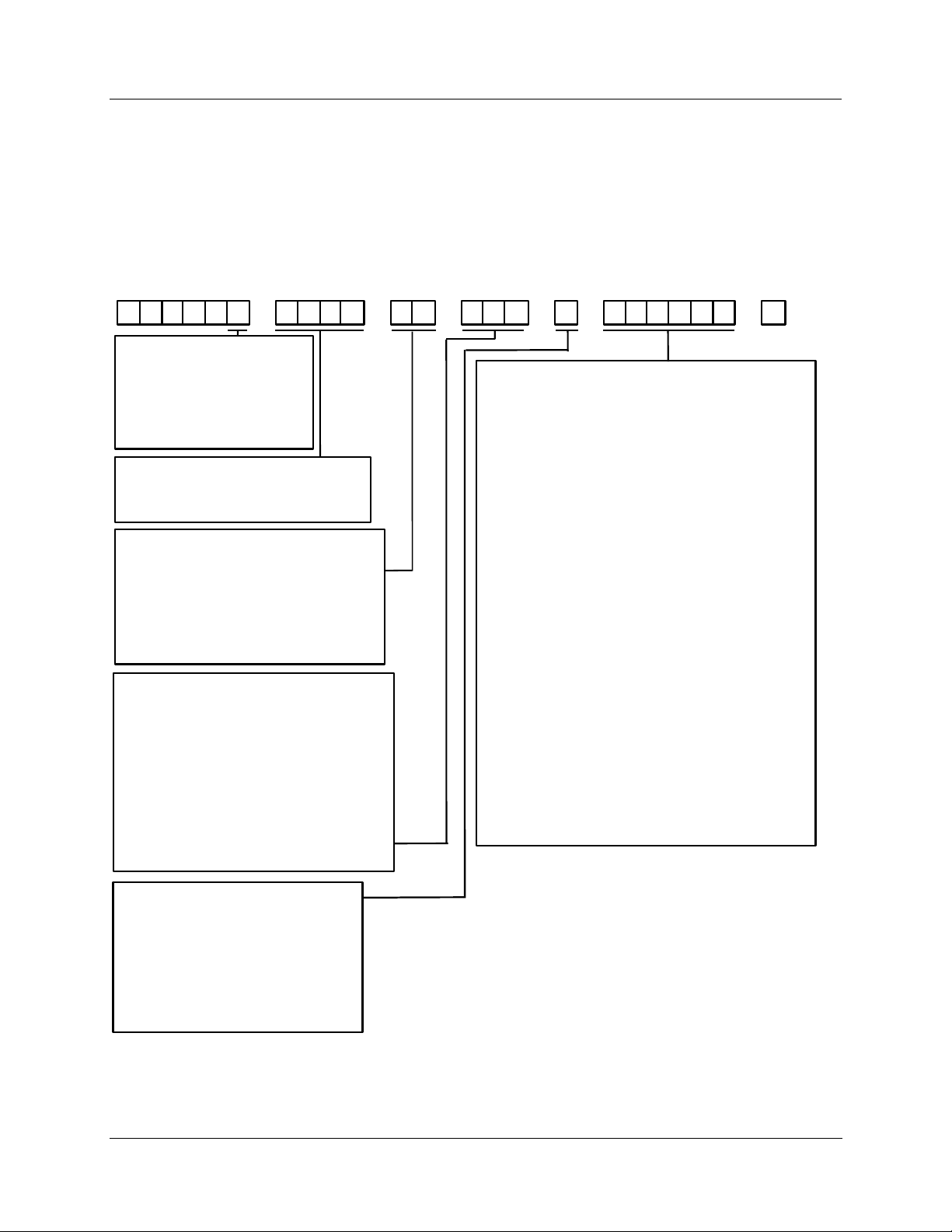
The model number interpretation is shown in Figure 2-1. Write the model number into the spaces provided
and compare it to the model number interpretation. This information will also be useful when you wire
your recorder. The example on the next page will help you to decode the model.
Table 1 Table 2 Table 3 Table 4 Table 5Key Number
DR45A 00
Key Number
T
=
Standard Recorder
R
=
Relay expansion Recorder
W
=
Flow Recorder
H
=
HTST
P
=
Pasteurization Recorder - Flow
S
=
Safety Thermal Limit Recorder
Input Actuation (Note 1)
0
None
=
1
T/C, RTD, Radiamatic , mV, 0–5V, 4–20mA
=
3
0–10 Vdc
=
External Output
0 0
= None
1 0
= 1 Control Output
1 1
= 2 Control Outputs
4 0
= 1 Control w/SP Programming
4 4
= 2 Controls w/SP Programming
5 0
= Pulse Output
6 0
= 1 Control Output with FM Approval
6 6
= 2 Control Outputs with FM Approval
External Interface
0 – –
= None
1 – –
= Auxiliary 4-20 mA Output
3 – –
= RS485 Modbus RTU**
4 – –
= RS485 Modbus RTU ** plus Auxiliary Output
– 0 –
= Standard Pen
– 1 –
= Abrasion Resistant Pen
– – 0
= None
– – 1
= 2 Alarm Outputs/2 Digital Inputs
– – 2
= 4 Alarm Outputs/2 Digital Inputs
– – 3
= 6 Alarm Outputs/2 Digital Inputs
– – 4
= 1 Alarm/1 Timer/2 Digital Inputs **
**Only available with key number DR45AT, AR, AW
––––– –
Hardware Options
0 - - - - 1 - - - - E - - - - F - - - - 5 - - - - 6 - - - - -
L - - - - 9 - - - - P - - - - R - - - - S - - - - -
- 0 - - - -
- A - - - -
- K - - - -
- - 0 - - -
- - L - - -
- - M - - -
- - N - - -
- - - 0 - -
- - - K - -
- - - L - -
- - - M - -
- - - N - -
- - - P - -
- - - R - - FM approved - Class 1, Div. 2, Groups A, B, C, D
- - - U - -
- - - - 0 -
- - - - T -
- - - - B -
- - - - C -
- - - - D -
- - - - E -
- - - - - 0
- - - - - 1
Gray door / Glass window
=
Gray door / Acrylic window
=
Gray door / Glass window and keypad
=
Gray door / Acrylic window and keypad
=
Blue door / Glass window
=
Blue door / Acrylic window
=
Black door / Glass window
=
Black door / Acrylic window
=
NEMA4X door / Glass window
=
NEMA4X door / Acrylic window
=
NEMA4X HTST door
=
Standard door latch
=
Keyed latch
=
Door lock with key
=
No illumination
=
Configuration lockout / Chart plate seal
=
Configuration Lockout / Chart plate seal / Illumination
=
Chart illumination
=
No approvals
=
CE Mark
=
CE Mark + UL + CSA certification
=
CE Mark + FM approval
=
CE Mark + UL + FM / CSA certification
=
UL listing + CSA certification
=
=
UL listing + CSA certification + FM approval
=
No I.D. Tag
=
Customer I.D. Tag (30 characters maximum)
=
Certificate of Conformance (F3391)
=
Custom Calibration / Test Report (F3399)
=
Certificate of Conformance + I.D. Tag
=
Customer Calibration + I.D. Tag
=
None
=
Product Configuration
=
Installation
Table 6
Software Options
0
= None
A
= Totalization , Input 1
B
= Math Only
E
= Totalization , Inputs 1 & 2
F
= Fo Sterilization Calculation
H
= Totalization , Inputs 1, 2, 3, & 4
K
= Totalization , Input 1 + Math
L
= Totalization , Input 1 and 2 + Math
M
= Totalization, Input 1, 2, 3, 4 + Math
NOTE 1:
Every DR4500A recorder has all the available inputactuations stored in its nonvolatile memory
and can accept up to 4 inputs which must be specified sequentially in 1–4 entries in Table 1.
Therefore, you can easily change the input actuation in the field by re-wiring input connections,
changing the input jumper position, and reconfiguring the input type, as applicable.
Figure 2-1 Model Number Interpretation
Release L DR4500A Truline Circular Chart Recorder With or Without Control Product Manual 13
8/02
Page 28

Installation
Model Number Interpretation
Example of model number decoding
Assume that the model number on the label is
DR45AT - 1300 - 44 - 001 - A - 1KN0T0 - 0
Using the table code definitions from Figure 2-1, this recorder has the following features and options:
• 2-input type with thermocouple, RTD, Radiamatic, mV, 0-5 Vdc or 4-20 mA input for channel 1
• 0-10 Vdc input for channel 2
• Two controllers with setpoint programming capability
• Alarm output / digital input capability
• High speed pen
• Totalization for input 1
• Gray door with acrylic window
• Door lock
• Chart illumination
• Customer I.D. tag
• No approvals
Location of hardware components
After you decode your recorder’s model number, refer to Figure 2-2 to match “table” selections with the
location of actual recorder hardware components. This will help you to determine applicable input / output
wiring requirements, as well as identify appropriate software functions to be configured later.
To access and view the actual components inside your recorder, follow the procedure in Table 2-2.
Table 2-2 Procedure to Access Components
Step Action
1 Turn the latch on the recorder door and swing the door open.
2
Loosen the captive screw on the right hand side of the chart plate and swing the chart plate
out.
3 Reverse the steps to close the chart plate and door.
14 DR4500A Truline Circular Chart Recorder With or Without Control Product Manual Release L
8/02
Page 29
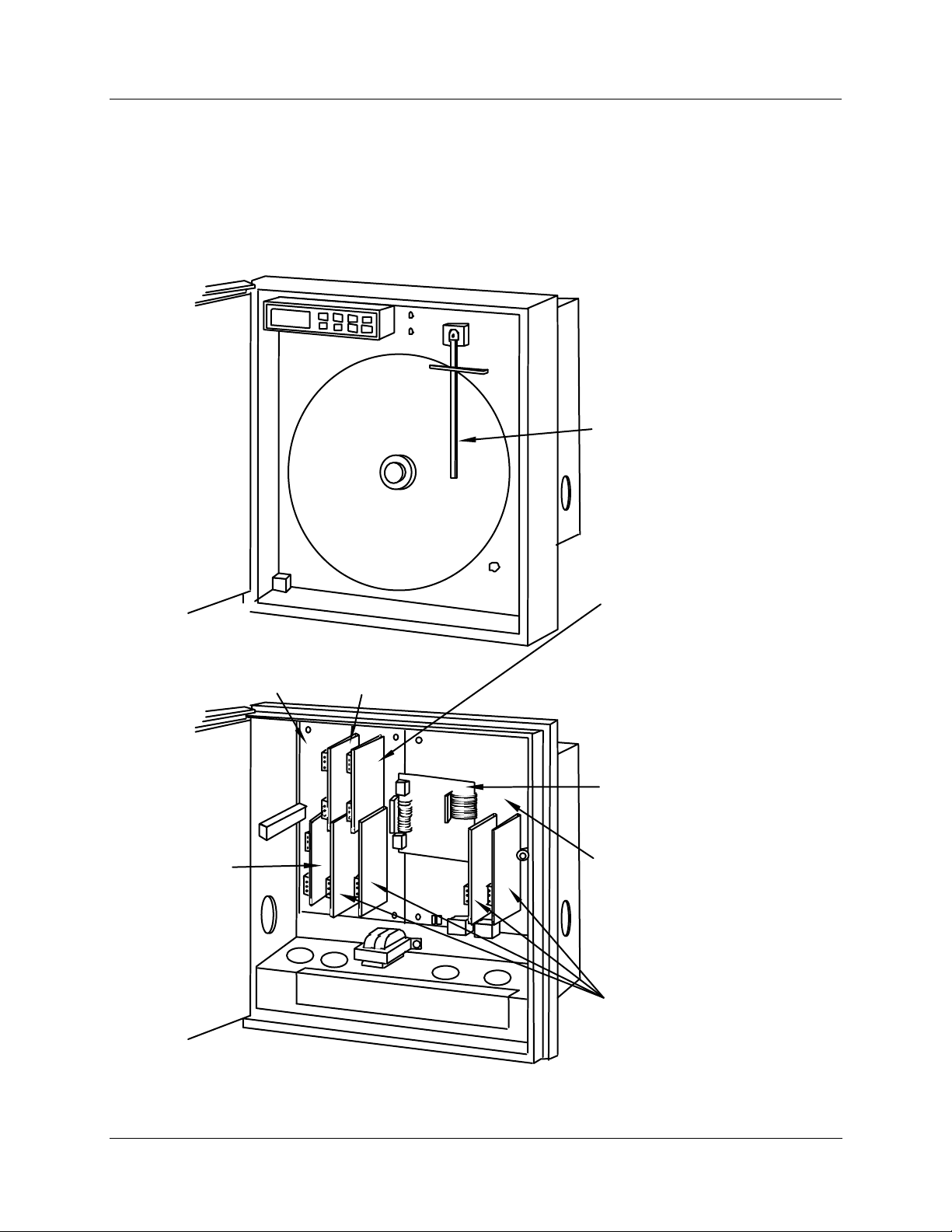
View of hardware components
Figure 2-2 shows the location of the actual hardware components for key number DR45AT. If key number
is DR45AR, see Appendix A for internal views.
Key Number: DR 45AT*
* If Key number is DR45AR, see Appendix A for internal views.
Installation
Model Number Interpretation
"One-Pen"
stylus
printhead
Mother PCB (for #3, #4 inputs,
control and selected options)
Control output
#2 PCB
**Table II - X1,
X4, X6
Control output #1 PCB
**Table II - 1X, 4X, 6X
#3
#4
#2 #1
Auxiliary Output PCB
**Table III - 1XX
OR
RS485/422 Modbus
Communications PCB
**Table III - 3XX
OR
Auxiliary Output and
RS485/422 Modbus
Com PCB
**Table III - 4XX
Alarm output/
digital input PCB
**Table III - XX1
Main
Processor
Board
Input PCB's
**Table I - XXXX
x = 0,1, or 3
** Refer to Model Selection Guide
21404
Figure 2-2 DR4500A Recorder Hardware Components Versus “Table” Selections
Release L DR4500A Truline Circular Chart Recorder With or Without Control Product Manual 15
8/02
Page 30
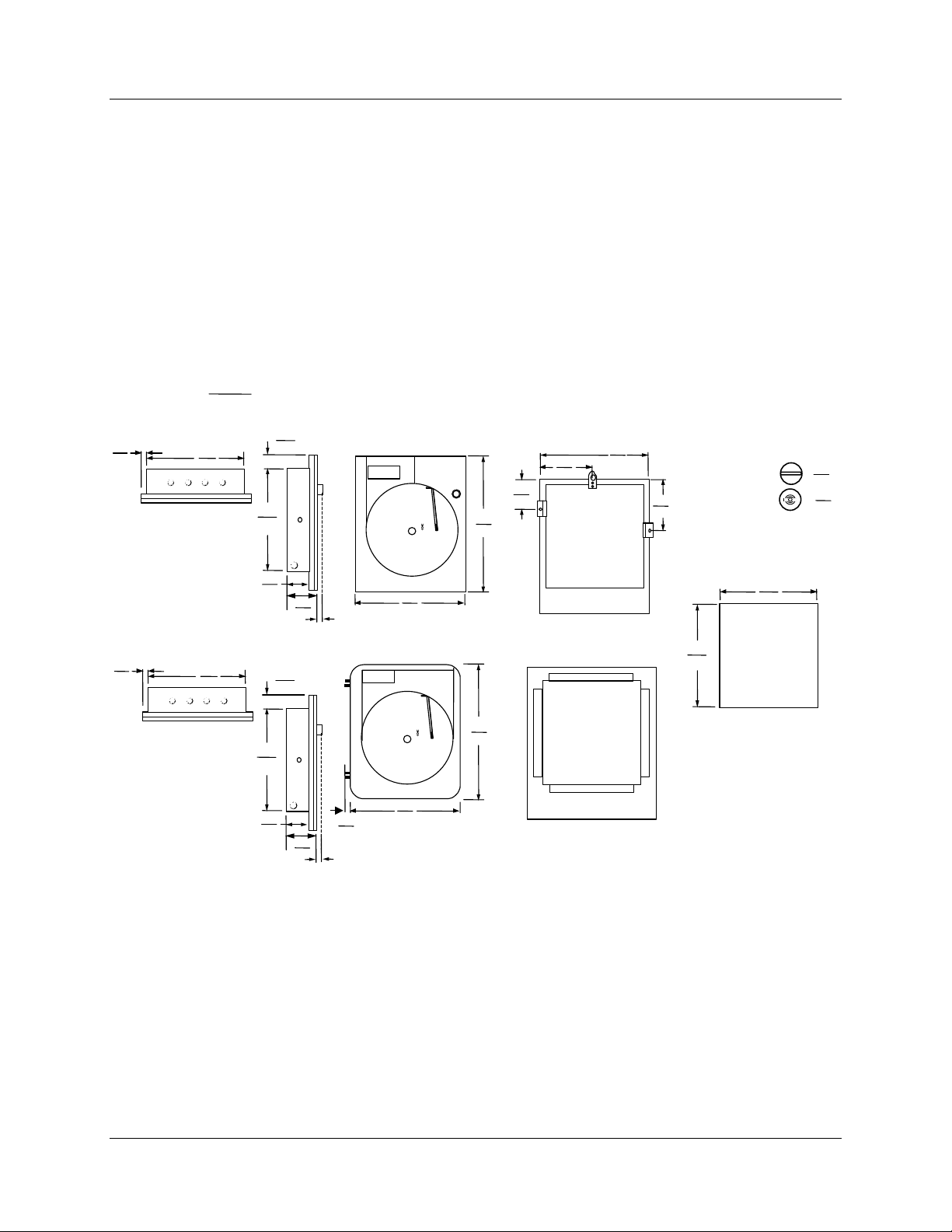
Installation
B
F
P
B
L
D
F
N
X
B
B
Mounting Considerations and Overall Dimensions
2.3 Mounting Considerations and Overall Dimensions
Physical considerations
The recorder can be mounted in a panel by making a new cutout or using an existing cutout with a filler
plate (see Table 2-4). Use the mounting kit supplied. Adequate access space must be available at the back
of the panel for installation and servicing activities.
The overall dimensions and panel cutout requirements for mounting the recorder are shown in Figure 2-3.
Overall dimensions
Figure 2-3 shows the overall dimensions for mounting the recorder.
321
12.6
ottom view
millim e te rs
in ch e s
Reference
20.3
0.8
321
12.6
419
16.5
163
6.4
196
7.7
Surface mounting
14.6
370
181
7.1
Dime ns ions :
Standard DR4500
17.5
0.69
Short wing latch :
ouble bit latch :
e ft side view
14.5
.57
5
.19
NEMA4X DR4500
17.5
0.69
ottom view
321
12.6
106
4.2
Reference
20.3
0.8
321
12.6
106
4.2
142
142
322
355
5.6
11.0
.43
5.6
14
ron t vie w
387
15.25
ron t vie w
EMA4
438
17.25
z
z
z
Surface mounting
z
z
zzzzz
zzzzz
ack vie w
ack view
322
12.7
z
z
z
z
z
12.7
anel cutout (all models)
Figure 2-3 Overall Dimensions
16 DR4500A Truline Circular Chart Recorder With or Without Control Product Manual Release L
8/02
Page 31
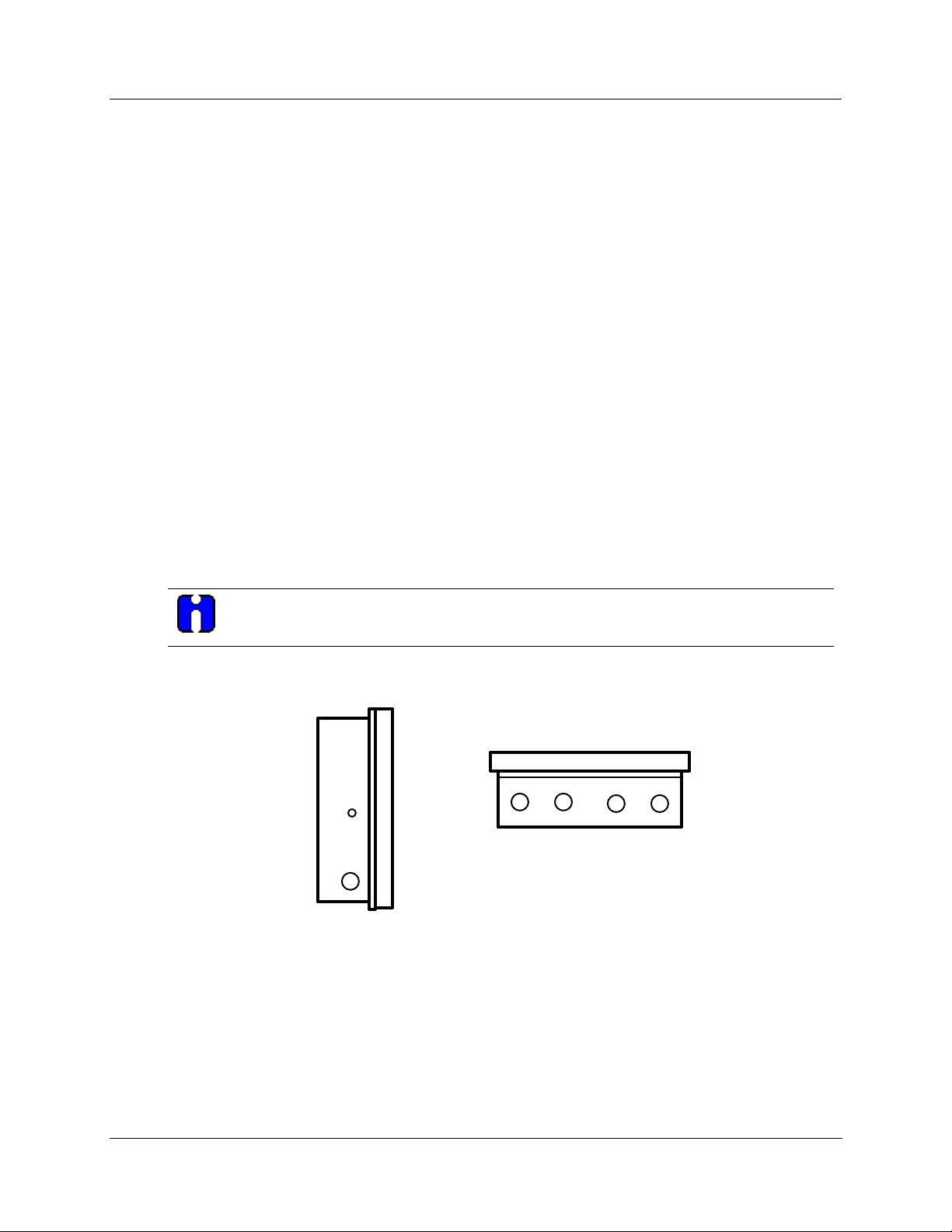
2.4 Mounting Methods
Introduction
There are several methods available for mounting your recorder.
• Flush in Panel (new panel cutout)
• Flush in Panel (using an existing panel cutout)
− using universal filler plate kit
− using cutout made for Kent Model 105M
• Flush in Panel for recorders with NEMA4 Door
• On a 2-inch Pipe
• On Surface (of panel or wall)
Procedures for each method follow. Choose the one that meets your mounting requirements. Use the
associated dimension drawings for reference.
How to remove knockouts for conduits
Installation
Mounting Methods
Before you mount the recorder, remove the appropriate “knockouts” in the bottom and/or sides of the
recorder case for wire entry via 1/2" (12.7 mm) conduits. Refer to Figure 2-4 for knockout locations.
ATTENTION
The knockouts are really plugs that you just have to push out to remove.
Side View
Bottom View
21405
Figure 2-4 How to Remove Knockouts
Release L DR4500A Truline Circular Chart Recorder With or Without Control Product Manual 17
8/02
Page 32
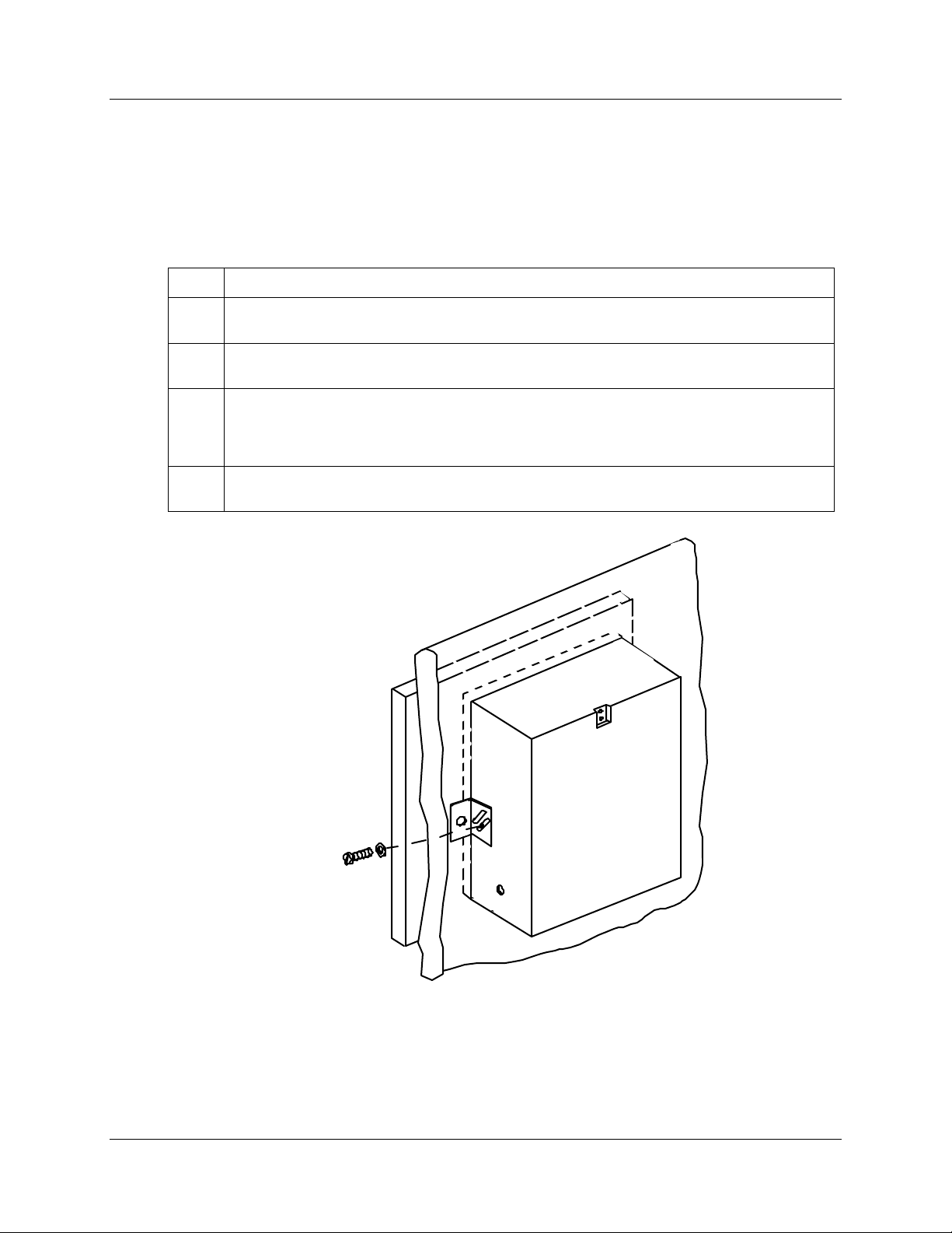
Installation
Mounting Methods
Mounting flush in panel (New panel cutout)
Refer to Figure 2-5 and follow the procedure in Table 2-3 to make a new cutout in a panel and mount your
recorder in the cutout.
Table 2-3 Mounting Flush in a New Panel Cutout
Step Action
1
At the appropriate location, make a square cutout in the panel measuring 12.7 ± 0.060 inches
by 12.7 ± 0.060 inches (322.58 ± 1.52 by 322.58 ± 1.52 millimeters). See Figure 2-3.
2
Orient the recorder case properly and slide it into the cutout from the front of the panel.
Support the recorder as shown in steps 3 and 4.
3
Refer to Figure 2-5. From the back of the panel, attach a mounting bracket to each side of the
recorder case using a 1/4-20 x 1/2 inch hex screw and a lockwasher for each bracket
(mounting hardware supplied with recorder). Leave the screws slightly loose so you can adjust
the brackets.
4
While holding the recorder firmly against the panel, slide each bracket against the back of the
panel and tighten the screws.
Hex screw,
1/4-20 x
1/2 inch and
washer
21406
Figure 2-5 Mounting Flush in a New Panel Cutout
18 DR4500A Truline Circular Chart Recorder With or Without Control Product Manual Release L
8/02
Page 33

Mounting Methods
Reference data for existing panel cutouts
Refer to Table 2-4 to determine whether the existing panel cutout can be used. Use the procedure for
mounting with the universal filler kit unless otherwise noted.
Table 2-4 Reference Data for Mounting DR4500A in Existing Panel Cutouts
Manufacturer / Instrument
Honeywell/Model AR100*, DR4200 12.7 x 12.7 No*
Honeywell/Class 15 15.8 x 17.2 Yes
Honeywell/Class 45 13.12 x 17.12 Yes
Badger Meter/Model Micro Chart 14.25 x 17.88 Yes
Bristol/Models 4330, 500 Classes 1, 2A, 3B, and 5 3.56 x 18.56 Yes
Fisher and Porter/Model 51-1100 13.75 x 17.31 Yes
Dimensions of Existing
Panel Cutout (inches)
Need Universal Filler
Plate Kit
30755134-001 Blue Color
30755134-002 Gray Color
Installation
Foxboro/Model 40 14.38 x 17.06 Yes
Kent/Model 105M** 13.6 x 13.46 No**
Partlow/Model ER* 13.5 x 12.69 No*
Taylor/Model 76J 13.78 x 16.5 Yes
*No adaptation is required, use procedure for “Flush in Panel - New Panel Cutout”
**Use procedure for “Cutout made for Kent Model 105M”
Adapter plate dimensions
The dimensions of the adapter plate (part number 30755134) are 16.5” x 19”.
Release L DR4500A Truline Circular Chart Recorder With or Without Control Product Manual 19
8/02
Page 34
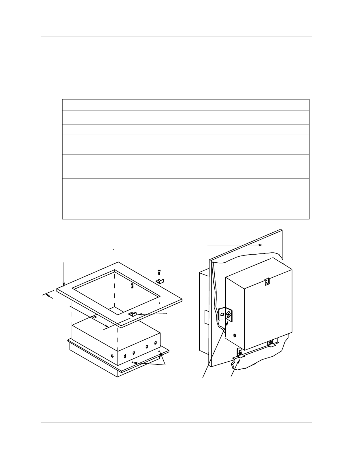
Installation
Mounting Methods
Mounting flush in panel (using universal filler plate kit)
Refer to Figure 2-6 and follow the procedure in Table 2-5 to mount your recorder in an existing cutout
using the Universal Filler Kit.
Table 2-5 Mounting Flush in a Panel Using Universal Filler Kit
Step Action
Lay the recorder face down on a clean work surface and position the universal filler plate as
1
shown in Figure 2-6.
Measure the height of the existing panel cutout.
2
Refer to Figure 2-6. Position the support brackets, supplied with the kit, so that the distance
3
from the top of the “window” in the filler plate to the right angle of the support brackets is just
less than the height of the existing panel cutout.
Secure brackets with two 10-32 x 1/4 inch screws, provided in the kit, by inserting them
4
through the holes in the filler plate into the tapped screw holes in the recorder case.
Insert the recorder into the cutout from the front of the panel as shown in Figure 2-6.
5
Refer to Figure 2-6. From the back of the panel attach a mounting bracket to each side of the
6
recorder case using a 1/4-20 x 1/2-inch hex screw and a lockwasher for each bracket
(mounting hardware supplied with recorder). Leave the screws slightly loose so you can adjust
the brackets.
While holding the recorder firmly against the panel, slide each bracket against the back of the
7
panel and tighten the screws.
NOTE: Universal filler plate and attaching
hardware are included in kit 30755134-xxx
Universal
filler plate
Height
of
cutout
in
panel
Figure 2-6 Mounting in a Panel Using Universal Filler Kit
Universal
filler plate
Support
brackets
Tapped
screw holes
Mounting brackets (supplied
with recorder)
21407
Support brackets
(included in kit 30755134-xxx
20 DR4500A Truline Circular Chart Recorder With or Without Control Product Manual Release L
8/02
Page 35
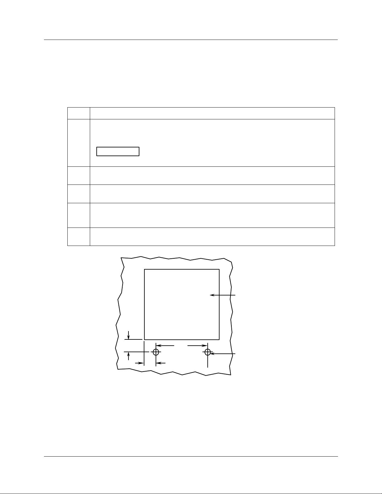
Mounting flush in panel (using cutout made for Kent Model 105M)
Refer to Figure 2-7 and follow the procedure in Table 2-6 to mount your recorder in an existing cutout
using the cutout made for Kent Model 105M.
Table 2-6 Mounting Flush in a Panel Using Kent Model 105M Cutout
Step Action
1
Drill two 1/4-inch holes in the back of the panel as shown in Figure 2-7. These holes are for 1032 screws to be inserted from back of panel into threaded inserts in the back of the recorder
case.
Installation
Mounting Methods
ATTENTION
screws for the 3/8-inch long screws supplied with the recorder.
2
While supporting the recorder, insert it through the panel cutout and orient the case so that the
threaded inserts at the bottom of the case align with the holes drilled in the panel.
3
From the rear of the panel, insert two 10-32 pan head screws of appropriate length into
threaded inserts in the recorder case.
4
From the back of the panel, attach a mounting bracket to each side of the recorder case using
a 1/4-20 x 1/2-inch hex screw and a lockwasher for each bracket (mounting hardware supplied
with recorder). Leave the screws slightly loose so you can adjust the brackets.
5
While holding the recorder firmly against the panel, slide each bracket against the back of the
panel and tighten the screws.
If the panel is more than 1/4-inch thick, substitute 10-32 x 1/2-inch long
Cutout for
Kent model 105M
2"
7 "
Drill two
3-1/2"
1/4-inch holes
21408
Figure 2-7 Mounting in a Panel using Kent Model 105M Cutout
Release L DR4500A Truline Circular Chart Recorder With or Without Control Product Manual 21
8/02
Page 36

Installation
Mounting Methods
Panel mounting recorder with NEMA4X door
Refer to Figure 2-8 and follow the procedure in Table 2-7 to panel-mount your recorder if it has a
NEMA4X door.
Table 2-7 Procedure for Mounting Recorder with NEMA4X Door
Step Action
1 Place the panel gasket onto the rear flange of the recorder case.
2
Install five #8-32 x 3/4 screws on each of the four mounting brackets so the ends of the screw
threads are flush with the face of the bracket.
NOTE: Screw heads to be flange side of brackets.
3 Insert the case with gasket into the panel opening.
4
Position the bracket so that the tabs on the end of the bracket slide into the holes in the case,
Secure the four brackets with 1/4-20 x 5/8 long bolts and lockwashers; one to the top, bottom
and each side of the case. Tighten the bolts.
5
Start to tighten the #8-32 x 3/4 screws on a bracket. Tighten the end screws first then those
toward the middle until all five screws have a 5 to 8 lb-in of torque applied. Do the same to
both the other three brackets.
When completed all twenty screws should have a 5 to 8 lb-in of torque applied. This assures
that the case and panel gaskets are adequately sealed against the panel.
22 DR4500A Truline Circular Chart Recorder With or Without Control Product Manual Release L
8/02
Page 37
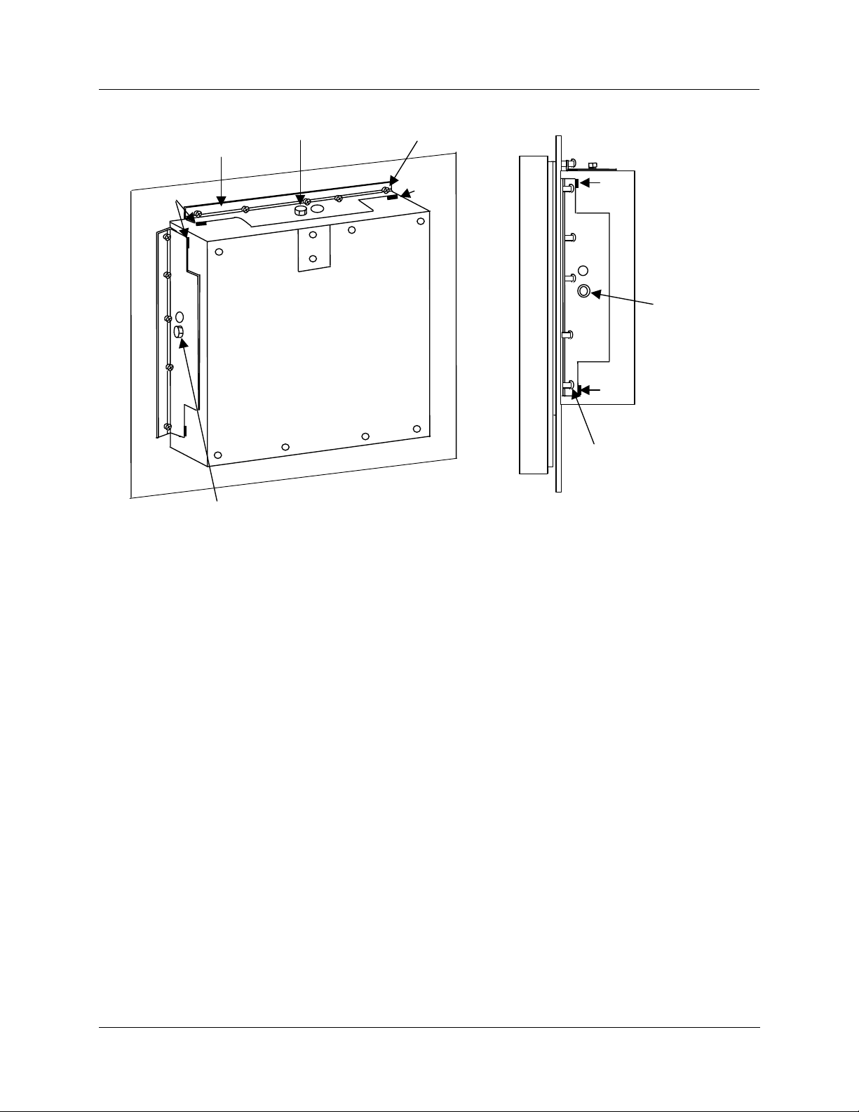
Installation
Mounting Methods
Slot
Bracket (4)
Hex Head Bolt
1/4-20 x 5/8 inch
Hex Head Bolt
1/4-20 x 5/8 inch
Pan Head Screw
8-32 x 3/4 inch
Slot
Slot
Hex Head Bolt
1/4-20 x 5/8 inch
Slot
Pan Head Screw
8-32 x 3/4 inch
Side View
NOTE: Mounting brackets, attaching hardware, and panel gasket are included in kit 30755065-503;
Figure 2-8 Panel Mounting Recorder with NEMA4X Door
Release L DR4500A Truline Circular Chart Recorder With or Without Control Product Manual 23
8/02
Page 38
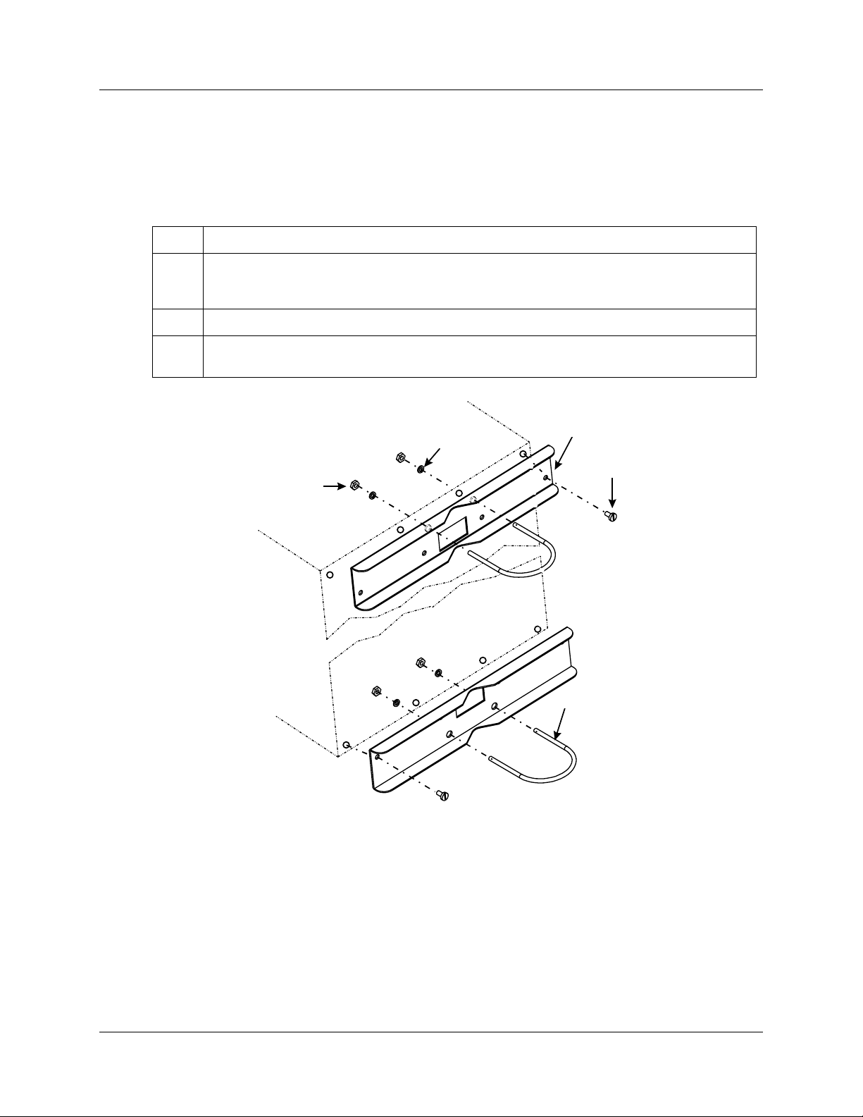
Installation
Mounting Methods
Mounting on a 2-inch pipe
Refer to Figure 2-9 and follow the procedure in Table 2-8 to mount your recorder on a 2-inch pipe.
Step Action
1
Using the eight plastite screws supplied with the pipe mounting bracket kit, attach the two
mounting brackets (flat side against the case) to the back of the recorder. Refer to Figure 2-9
for location.
2 Position the recorder with brackets on the 2-inch pipe.
3
Install the U-bolts around the pipe and through the bracket holes. Secure with lockwashers and
hex nuts provided.
Table 2-8 Pipe Mounting Procedure
Washer
Hex Nut
Pipe Mounting
Bracket
Plastite
Screw
Rear
of
Case
U-bolt
24224
Figure 2-9 Pipe Mounting Brackets
24 DR4500A Truline Circular Chart Recorder With or Without Control Product Manual Release L
8/02
Page 39

Mounting on surface (of panel or wall)
Refer to Figure 2-10 and follow the procedure in Table 2-9 to mount your recorder on a surface (panel or
wall).
ATTENTION
You must supply three (3) screws for attaching the mounting hardware (brackets and support
hook) to panel or wall.
Table 2-9 Mounting Flush on a Surface (of Panel or Wall)
Step Action
1
Using two flat-head 10-32 x 1/4-inch screws supplied with the recorder, fasten the support
hook into the recess at the back of the recorder case as shown in Figure 2-10.
2
Using 1/4-20 x 1/2-inch hex screws and lockwashers, attach a mounting bracket to each side
of the case. Leave the screws slightly loose so as to permit some adjustments of the brackets.
3
On the panel mark the locations for the three holes as shown by the hole pattern in Figure
2-10.
Installation
Mounting Methods
4
Using a drill of appropriate size for user-supplied screws, drill a hole in the front of the panel for
the eye of the support hook.
5
Insert the screws for the support hook into the panel, allowing the screw head to protrude
approximately 5/16-inch.
6
Hang the recorder support hook on the screw. Make sure that the locations for the other two
holes (marked in step three) are correct. If not, make sure that the recorder is aligned vertically
and use the brackets as templates to mark the proper locations.
7 Remove the recorder from the panel and drill the other two holes.
8
Hang the recorder on the screw by the support hook and insert the other two user-supplied
screws through the brackets into the panel. Tighten the two hex screws that attach the
brackets to the case.
Release L DR4500A Truline Circular Chart Recorder With or Without Control Product Manual 25
8/02
Page 40
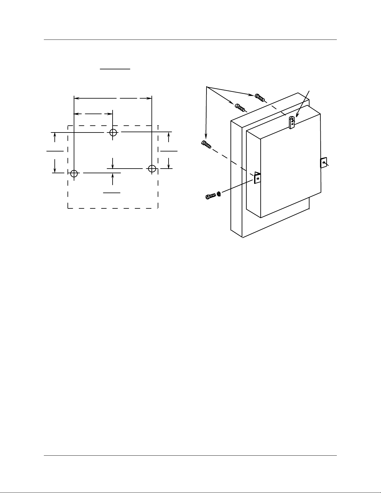
Installation
Mounting Methods
181.36
7.14
Hole Pattern
Reference:
196.22
7.725
millimeters
inches
These screws must be supplied by
user; all other mounting hardware
is supplied with recorder.
369.6
14.550
163.32
6.430
18.03
0.710
Figure 2-10 Mounting Flush on a Surface (of Panel or Wall)
NOTE:
Support
hook
21409
26 DR4500A Truline Circular Chart Recorder With or Without Control Product Manual Release L
8/02
Page 41
2.5 Wiring Prerequisites
Taking electrical noise precautions
Electrical noise is composed of unabated electrical signals which produce undesirable effects in
measurements and control circuits.
Digital equipment is especially sensitive to the effects of electrical noise. Your recorder has built-in circuits
to reduce the effect of electrical noise from various sources. If there is a need to further reduce these
effects:
• Separate External Wiring - separate connecting wires into bundles (see Table 2-10) and route the
individual bundles through separate conduits or metal trays.
• Use Suppression Devices - for additional noise protection, you may want to add suppression devices at
the external source; appropriate suppression devices are commercially available.
REFERENCE
For additional noise information, refer to document number 51-52-05-01.
Electrical considerations
The recorder is considered “rack and panel mounted equipment” per EN 61010-1, Safety
Requirements for Electrical Equipment for Measurement, Control, and Laboratory Use, Part
1: General Requirements.
Installation
Wiring Prerequisites
Recorder grounding
PROTECTIVE BONDING (grounding) of this recorder shall be in accordance with National
and local electrical codes.
Functional earth
To minimize electrical noise and transients that may adversely affect the system,
supplementary bonding of the recorder enclosure to a functional earth ground, using a 3/4”
braided copper conductor, is required.
A terminal on the rear of the recorder is provided for this connection.
CE conformity special conditions (Europe)
Braid shielded cable is required for all Input I/O and Output Relay cables. All recorder cable shield wires,
except the RS485 Modbus communications cable shield, must be connected to a low impedance earth
ground at the recorder. This can be done by bussing the shields to an earth ground point, or by connecting
the shields to the conduit entry fittings if they are in electrical contact with the enclosure conductive
coating. In either case, the shields shall not extend into the recorder enclosure. The cable shields shall also
be connected to a low impedance earth ground at the farthest end of the cable, through a 0.0047 uF
capacitor. See each of the individual wiring diagrams.
Release L DR4500A Truline Circular Chart Recorder With or Without Control Product Manual 27
8/02
Page 42

Installation
Wiring Prerequisites
For the RS485 Modbus communications cable, Alpha XTRA Guard I cable (Alpha P/N 5121C) is required.
At the recorder end, the communications cable shield must be unconnected and must not extend into the
recorder enclosure. The shield of the communications cable must be connected to earth ground at the
farthest end of the cable. See the option wiring procedure for the RS485 Communications Card.
Inside of the enclosure, the user must install ferrite suppression filters and capacitors on all wires connected
to the recorder. ©Fair-Rite Products Corp. part number 0443164151, or equivalent, shall be installed as
shown in Figure 2-11 to Figure 2-22, one filter for each circuit group.
Cable with an outer jacket diameter larger than 6.7 mm (0.264 in.) may require the outer jacket to be
removed to fit the required one turn in the filter, or the selection of a different cable.
Permissible wire bundling
Table 2-10 shows which wire functions should be bundled together.
Bundle No. Wire Functions
Table 2-10 Permissible Wiring Bundling
1 • Line power wiring
• Earth ground wiring
2 Analog signal wire, such as:
3 • Low voltage alarm relay output wiring
Identify your wiring requirements
To determine the appropriate diagrams for wiring your recorder, refer to the model number interpretation in
this section. The model number of the recorder can be found on the chart plate.
• Control relay output wiring
• Line voltage alarm wiring
• Input signal wire (thermocouple, 4 to 20 mA, etc.)
• 4-20 mA output signal wiring
• Slidewire feedback circuit wiring
• Digital input signals
• Communications
• 4-20 mA auxiliary output
• Low voltage wiring to solid state type control circuits
28 DR4500A Truline Circular Chart Recorder With or Without Control Product Manual Release L
8/02
Page 43

2.6 Input Wiring Procedures
Wiring the recorder
Using the information contained in the model number, select the appropriate wiring diagrams from the
figures listed below and wire the recorder accordingly.
Wiring Requirements Refer to
Ferrite Filter Locations Figure 2-11
AC Line Power Figure 2-12
Thermocouple, RTD, Radiamatic, mV, or 0–5 Vdc Inputs Figure 2-13
4–20 mA Inputs Figure 2-14
0–10 Vdc Inputs Figure 2-15
4–20 mA Current Outputs or Auxiliary Outputs #2 and #3 Figure 2-16
Position Proportional Control Outputs Figure 2-17
Installation
Input Wiring Procedures
Relay Control Outputs
– Time Proportioning
Alarm #1 and #2 Outputs and Digital Inputs Figure 2-19
Alarm Outputs #3, #4, #5, and #6 Figure 2-20
RS485 Modbus Communications Figure 2-21
Auxiliary Output #1 Figure 2-22
Ferrite filter locations (CE Mark)
Inside of the enclosure, install ferrite suppression filters on all wires connected to the recorder. ©Fair-Rite
Products Corp. part number 0443164151, or equivalent, shall be installed as shown in Figure 2-11, one
filter for each circuit group. Cable with an outer jacket diameter larger than 6.7 mm (0.264 in.) may require
the outer jacket to be removed to fit the required one turn in the filter, or the selection of a different cable.
Shield Wiring
The shield wires of all cables, except the RS485 communications cable, should be tied to earth ground at
the recorder end and to earth ground through a .0047 µF Capacitor at the other end of the cable. An
example of shield wiring to an external ground bus bar is shown in Figure 2-11.
Figure 2-18
Release L DR4500A Truline Circular Chart Recorder With or Without Control Product Manual 29
8/02
Page 44
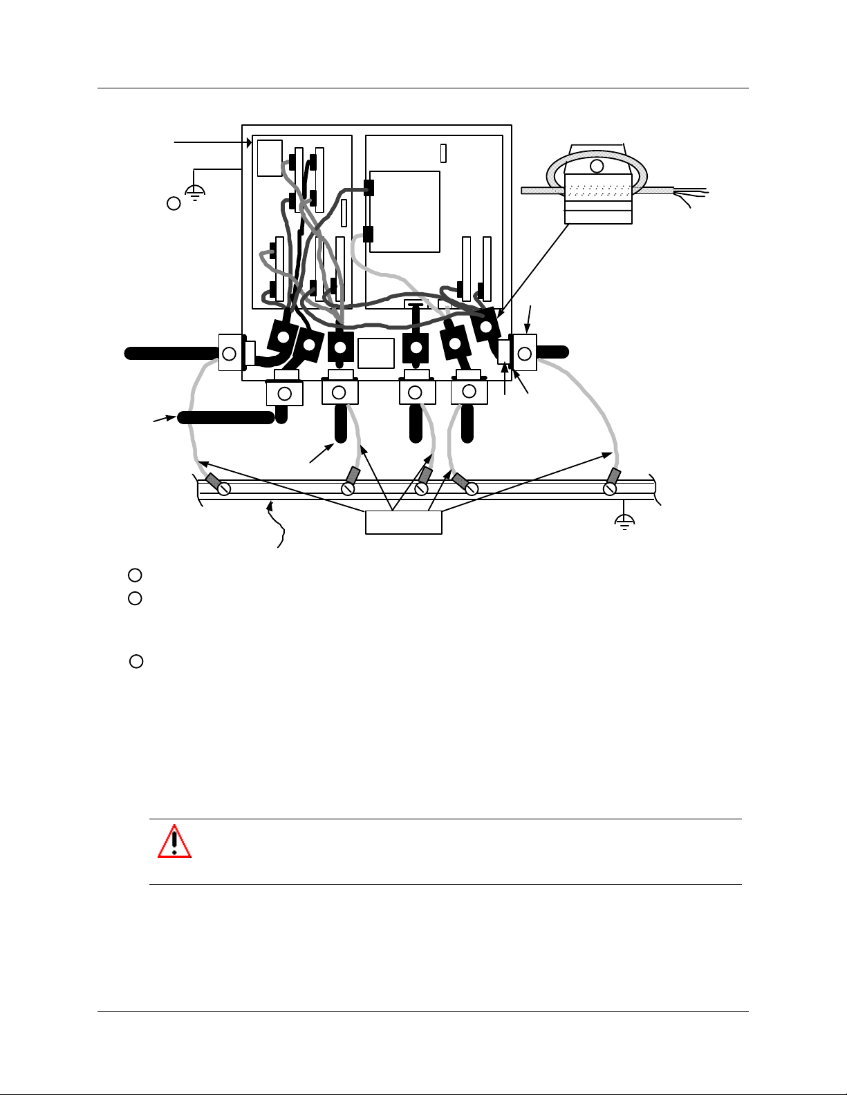
Installation
Input Wiring Procedures
Mother PCB
1
Control Loop 1
and Loop 2
Output Relays
Alarm Relays
RS485/422 Modbus
Communications
External Ground Bus Bar
3
2
3
2
Current Output 1 & 2
Slidewire 1 & 2
Auxiliary Output
Number
1 & 2
Alarm/
Digital
Inputs
Transformer
A.C.
Main
Shield Wiring
33
22
Processor
Board
3
3
2
Digital Inputs 1 & 2
Transmitter Power
2
Hex Nut
Ferrite Filter
3
Cable Fitting
Inputs 1–4
Washer
To Earth Ground
1 Recorder Grounding, rear of case - Use 3/4 inch braided copper conductor.
2
Use Cable fitting to support wiring and hold in place.
Place the washer on the inside of the recorder between
the case and the fastening nut to protect the recorder conductive
case coating.
3
Ferrite Filter location - Cable with an outer jacket diameter larger than 6.7 mm (0.264 in.)
may require the outer jacket to be removed to fit the required one turn in the filter,
or the selection of a different cable.
Figure 2-11 Ferrite Filter Locations and Shield Wiring (CE Mark)
AC line power
Refer to Figure 2-12 and follow the procedure in Table 2-11 to connect the AC line power.
WARNING
Be sure that the line voltage is OFF before connecting the power wires to the recorder
or personal injury could result.
This equipment is suitable for connection to 120/240 Vac, 50/60 Hz, power supply mains. It is the user’s
responsibility to provide a switch and non-time delay (North America), quick-acting, high breaking
capacity, Type F, (Europe) 1/2 A, 250 V fuse(s) or circuit-breaker as part of the installation. The switch or
circuit-breaker shall be located in close proximity to the recorder, within easy reach of the OPERATOR.
The switch or circuit-breaker shall be marked as the disconnecting device for the recorder.
23685
30 DR4500A Truline Circular Chart Recorder With or Without Control Product Manual Release L
8/02
Page 45
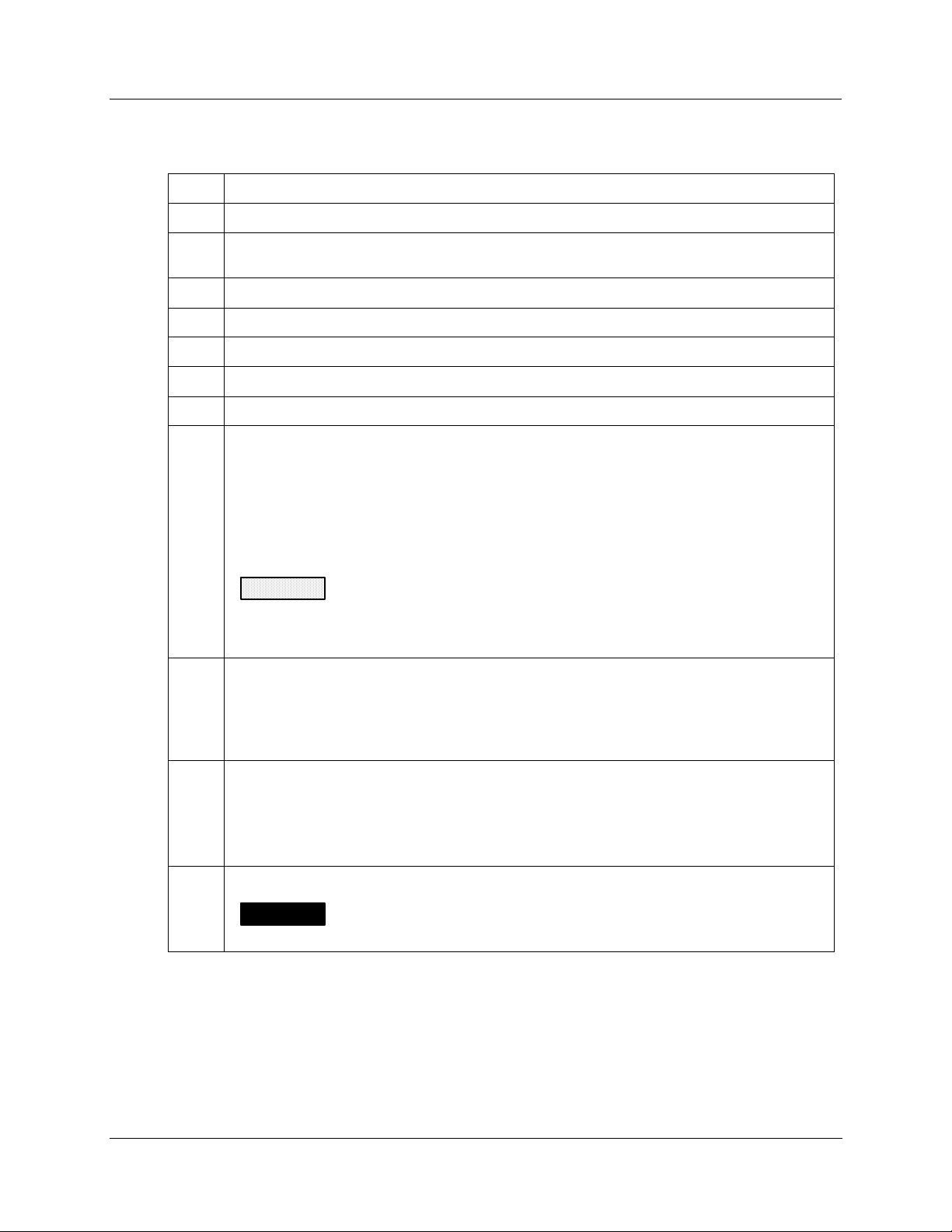
Installation
Input Wiring Procedures
Table 2-11 AC Line Power Wiring
Step Action
1 Open the recorder door. Loosen the captive screw in the chart plate and swing the plate out.
2
Locate connector J10 on the bottom edge of the main printed circuit board. (Refer to Figure
2-12.)
3 Remove the unwired plug from J10.
4 Run the power wires separately through second conduit from the right.
5 For CE Mark conformity, install the ferrite filter as shown in Figure 2-11.
6 Strip insulation from the end of each wire.
7 Loosen the screws in plug J10 terminals and position the plug as you would to plug it into J10.
8 Insert
• the green wire (G) into the first screw clamp from the right,
• the white wire (L2) into the second screw clamp from the right, and
• the black wire (L1) into the third screw clamp from the right.
Tighten the screws to secure the wires.
9
10
CAUTION
into the correct screw clamps. Make sure the fuse block is installed properly for the
given supply rating –– 120 Vac or 240 Vac. The fuse is in the 120 Vac location from the
factory.
Make sure the fuse block is installed in the proper location. Refer to Figure 2-12 for fuse block
location.
Dress the wires as slack as possible. This keeps the noise signal on these wires from
bypassing built-in suppression. Also, do not bundle any low level signal wires with the power
wires. Refer to Table 2-10 for permissible wire bundling.
• Refer to document 51-52-05-01 for additional information concerning noise interference
prevention.
To avoid damaging the recorder, be sure that you install the power wires
• 120 Vac – Fuse block in location F2
• 240 Vac – Fuse block in location F1
11 Insert the wired plug into J10.
WARNING
ground is not attached; personal injury and product damage could result.
Input line voltage will be present on the instrument ground plane if safety
Release L DR4500A Truline Circular Chart Recorder With or Without Control Product Manual 31
8/02
Page 46
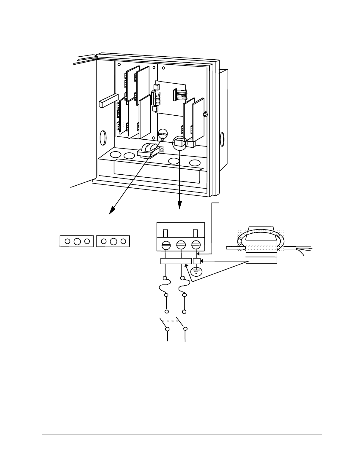
Installation
Input Wiring Procedures
#4
#3
#2 #1
Fuse Block on Main PC Board
P/N51309355-tab
F2
120 Vac
240 Vac
Required for CE Mark Conformity—
14 AWG Braided Wire to AC supply
PLUG J10
ground
F1
L1 L2
Required for CE Mark Conformity—
Kit supplied Part No. 51197612-502,
contains two ferrite filters. More than
one kit may be supplied. Install
inside of case. See Figure 2-11.
H
N
120 or 240 Vac
Figure 2-12 AC Line Power Wiring
Fair-Rite P/N 0443164151
or equivalent
21410B
32 DR4500A Truline Circular Chart Recorder With or Without Control Product Manual Release L
8/02
Page 47
Thermocouple, RTD, Radiamatic, mV, or 0-5 Vdc inputs
You can wire input 1, 2, 3, or 4 for thermocouple, RTD, Radiamatic, mV, or 0-5 Vdc actuations.
The polarity for inputs #1, #2, #3, and #4 is identical.
The prerequisites are:
• Model Number - Table 1 = 1XXX, X1XX, XX1X, XXX1
ATTENTION
For thermocouple or RTD inputs, calibrate the recorder to achieve the stated accuracy. Refer
to Section 7 – Input Calibration
Refer to Figure 2-13 and follow the procedure in Table 2-12 to wire Thermocouple, RTD, Radiamatic, mV,
or 0–5 Vdc inputs.
Table 2-12 Thermocouple, RTD, Radiamatic, mV, or 0–5 Vdc Input Wiring
Step Action
Installation
Input Wiring Procedures
1 Open the recorder door. Loosen the captive screw in the chart plate and swing the plate out.
2 Locate connector J2 on the printed circuit board for input 1 (refer to Figure 2-13).
3 Remove the unwired plug from J2.
4 Run the input wires through the desired knockout - DO NOT bundle them with the power wires.
5 For CE Mark conformity:
• Install the ferrite filter as shown in Figure 2-11.
• Install a .01 µF capacitor across the J2 terminals and a .0047 µF capacitor at the
sensor end of the input wiring as shown in Figure 2-13.
6
Locate jumper position MA/W1 and make sure the jumper is in the W1 position. (See Figure
2-13 for the location.)
7
Locate jumper position W3 and make sure the jumper is in the proper position for your input
type. (See Figure 2-13 for the jumper locations.)
8 Strip insulation from the end of each wire.
9 Loosen the screws in plug J2 terminals and position the plug as you would to plug it into J2.
10
Insert the wires into the appropriate screw clamps for the applicable input type. See Figure
2-13 for specific input actuation plug wiring. Tighten the screws to secure the wires.
11 Insert the wired plug into J2.
12 Repeat steps 2 through 11 for input 2, 3, and 4 printed circuit boards as applicable.
Release L DR4500A Truline Circular Chart Recorder With or Without Control Product Manual 33
8/02
Page 48
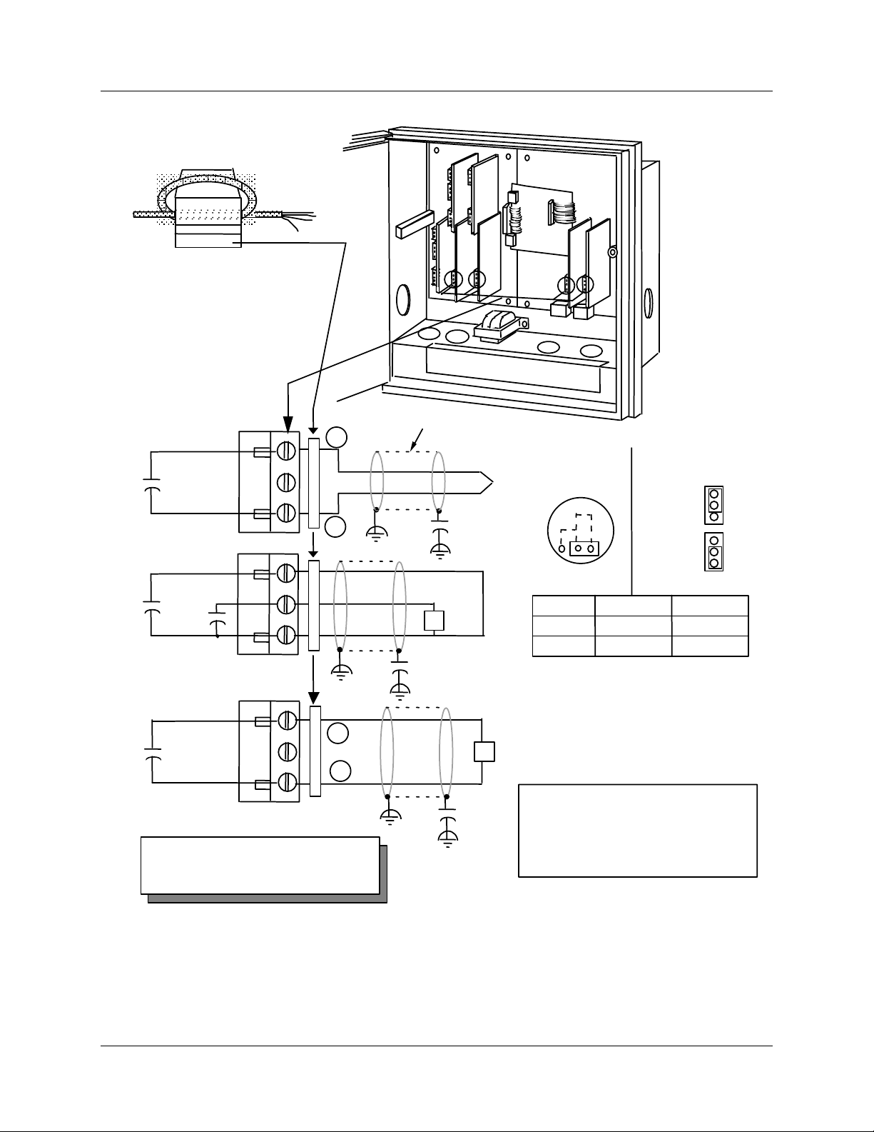
Installation
Input Wiring Procedures
Ferrite Filter
Fair-Rite P/N 0443164151
or equivalent
Required for CE Mark Conformity
Kit Part No. 51197612-502, contains two
ferrite filters; Part No.51197612-508
contains 8 ferrite filters. Install inside of
case. See Figure 2-11.
Capacitor Kit 51197755-001
Install capacitors as shown in figure.
Thermocouple
.01 µF
Capacitors
Plug J2
RTD
#3
#4
+
-
Cable Shield
.0047 µF
Capacitor
MA/W1 Jumper
position on input
T/C
board
MA
#2#1
W1
21411B
W3 Jumper
Positions
Thermocouple
Linear
MA
RTD
T/C
RTD
T/C
RTD
.01 µF
.01 µF
Capacitors
Plug J2
Radiamatic,
mV, or 0-5 Vdc
+
.01 µF
Capacitor
-
Plug J2
NOTE: For T/C or RTD input, calibrate
recorder to achieve stated accuracy.
See Section 7 - Input Calibration.
Figure 2-13 Thermocouple, RTD, Radiamatic, mV, or 0–5 Vdc Input Wiring
•
.0047 µF
Capacitor
RTD
.0047 µF
Capacitor
TYPE W1/MA W3
T/C, Linear
RTD
W1
W1
mV or Volt
source
Be sure that thermocouple extension
•
wire matches thermocouple type
•
Keep resistance of all wires equal
Use 18 gauge copper wire for lengths up to
•
150 feet.
For two wire RTD, jumper terminal 1 to 3.
•
T/C
RTD
34 DR4500A Truline Circular Chart Recorder With or Without Control Product Manual Release L
8/02
Page 49
4-20 mA inputs and transmitter power
You can wire input 1, 2, 3, or 4 for 4–20 mA actuations.
The polarity for inputs #1, #2, #3, and #4 is identical.
The prerequisites are:
• Model Number - Table 1 = 1XXX, X1XX, XX1X, XXX1
ATTENTION
Connector J11 on the main processor printed circuit board can be used to provide 24 Vdc
power to up to two field transmitters (without power) which are supplying the 4–20 mA input
signals to the recorder (1.2W @ 24 Vdc = 50 mA available).
Refer to Figure 2-14 and follow the procedure in Table 2-13 to wire 4-20 mA inputs.
Table 2-13 4-20 mA Input Wiring
Step Action
Installation
Input Wiring Procedures
1
2
3
4
5
6
7
8
9
10
11
Open the recorder door. Loosen the captive screw in the chart plate and swing the plate out.
Be sure that the jumper MA/W1 is installed in the position labeled “MA”; this connects an
internal 250-ohm resistor across the 4-20 mA input terminals on J2. (Refer to Figure 2-14 for
location of jumper.)
Locate jumper position W3 and make sure the jumper is in the proper position for your input
type (see Figure 2-14 for the location).
Locate connector J2 on the printed circuit board for input 1 (refer to Figure 2-14).
Remove the unwired plug from J2.
Run the input wires through the desired knockout - DO NOT bundle them with the power wires.
For CE Mark conformity, install the ferrite filter as shown in Figure 2-11 and the capacitors as
shown in Figure 2-14.
Strip insulation from the end of each wire.
Loosen the screws in plug J2 terminals and position the plug as you would to plug it into J2.
• For transmitters with power:
Insert the wires into the appropriate screw clamps and tighten the screws to secure the
wires.
ATTENTION
protection diode. The wake-up pulse on the ST3000 may not be recognized by the transmitter
due to this clamping action. It may be necessary to add 100 ohms of additional loop resistance
so the transmitter and SFC can communicate.
• For transmitters which require power:
Remove the unwired plug from J11 then wire the transmitter power to J11 and the
input to J2. Tighten the screws in the plugs to secure the wires.
Insert the wired plug into J2 and J11 as applicable.
The DR4500A Recorder inputs are protected from overvoltage by a
12
Release L DR4500A Truline Circular Chart Recorder With or Without Control Product Manual 35
8/02
Repeat steps 2 through 11 for input 2, 3, and 4 printed circuit boards as applicable.
Page 50
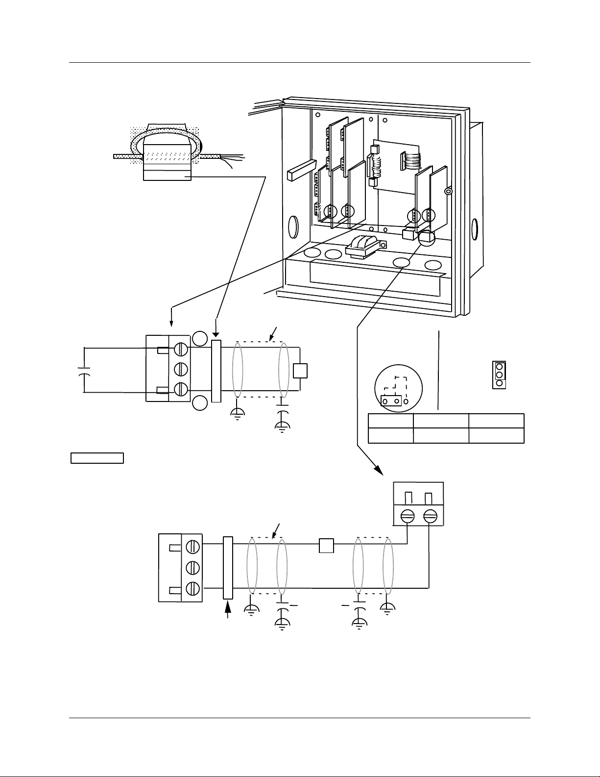
Installation
Input Wiring Procedures
Ferrite Filter
Fair-Rite P/N 0443164151
or equivalent
Required for CE Mark Conformity
Kit Part No. 51197612-502, contains two
ferrite filters; Part No.51197612-508
contains 8 ferrite filters. Install inside of
case. See Figure 2-11.
Capacitor Kit 51197755-001
Install capacitors as shown in figure.
VIEW A - From
transmitter with
power
.01 µF
4-20 mA
+
Cable Shield
_
Plug J2
ATTENTION
from overvoltage by a protection diode. The wake up pulse on
the ST3000 may not be recognized by the transmitter due to
this clamping action. It may be necessary to add 100 ohms of
additional loop resistance so the transmitter and SFC can
communicate.
The DR4500A Recorder inputs are protected
Cable Shield
VIEW B - From
4-20 mA
+
transmitter
receiving 24Vdc
power from
recorder
_
Plug J2
Ferrite filter
Figure 2-14 4-20 mA Input Wiring
.0047 µF
Capacitor
_
.0047 µF
Capacitor
#4
4 - 20 mA
source
+
Xmtr
#3
MA/W1 Jumper
position on input
board
MA
TYPE W1/MA W3
4-20mA
#2 #1
W1
M/A
Transmitter
power (24 Vdc)
Plug J11
+
_
21412B
W3 Jumper
Positions
Linear/MA
T/C
RTD
T/C
36 DR4500A Truline Circular Chart Recorder With or Without Control Product Manual Release L
8/02
Page 51
0-10 Volt dc inputs
You can wire input 1, 2, 3, or 4 for 0–10 Volt dc actuations.
The polarity for inputs #1, #2, #3, and #4 is identical.
The prerequisites are:
• Model Number - Table 1 = 3XXX, X3XX, XX3X, XXX3
ATTENTION
Calibrate the recorder to achieve the stated accuracy. Refer to Section 7 – Input Calibration.
Refer to Figure 2-15 and follow the procedure in Table 2-14 to wire 0-10 Vdc inputs.
Step Action
1 Open the recorder door. Loosen the captive screw in the chart plate and swing the plate out.
2 Locate connector J2 on the printed circuit board for input 1 (refer to Figure 2-15).
Installation
Input Wiring Procedures
Table 2-14 0-10 Volt dc Input Wiring
3
Remove the unwired plug from J2 and replace it with the modified 4-screw plug from the bag of
accessories supplied with the recorder.
4
Run the input wires through the desired knockout—DO NOT bundle them with the power
wires.
5 For CE Mark conformity:
• Install the ferrite filter as shown in Figure 2-11.
• Install the .01 µF capacitor and the .0047 µF capacitor as shown in Figure 2-15.
6 Strip insulation from the end of each wire.
7 Loosen the screws in plug J2 terminals and position the plug as you would to plug it into J2.
8
Using the 30755232-002, 100K-ohm, voltage divider connector kit supplied in the bag of
accessories, insert the wires into the appropriate screw clamps. Tighten the screws to secure
the wires.
9
Install the wired plug into J2. Since J2 has only three receptacles, one of the modified plug
connectors is designed to slide outside J2 when the plug is installed.
10
Locate jumper position W3 and make sure the jumper is in the proper position for your input
type. (See Figure 2-15 for the location.)
11 Locate jumper position MA/W1 and make sure the jumper is in the W1 position. (See Figure
2-15 for the location.)
12 Repeat steps 2 through 11 for input 2, 3, and 4 printed circuit boards as applicable.
Release L DR4500A Truline Circular Chart Recorder With or Without Control Product Manual 37
8/02
Page 52
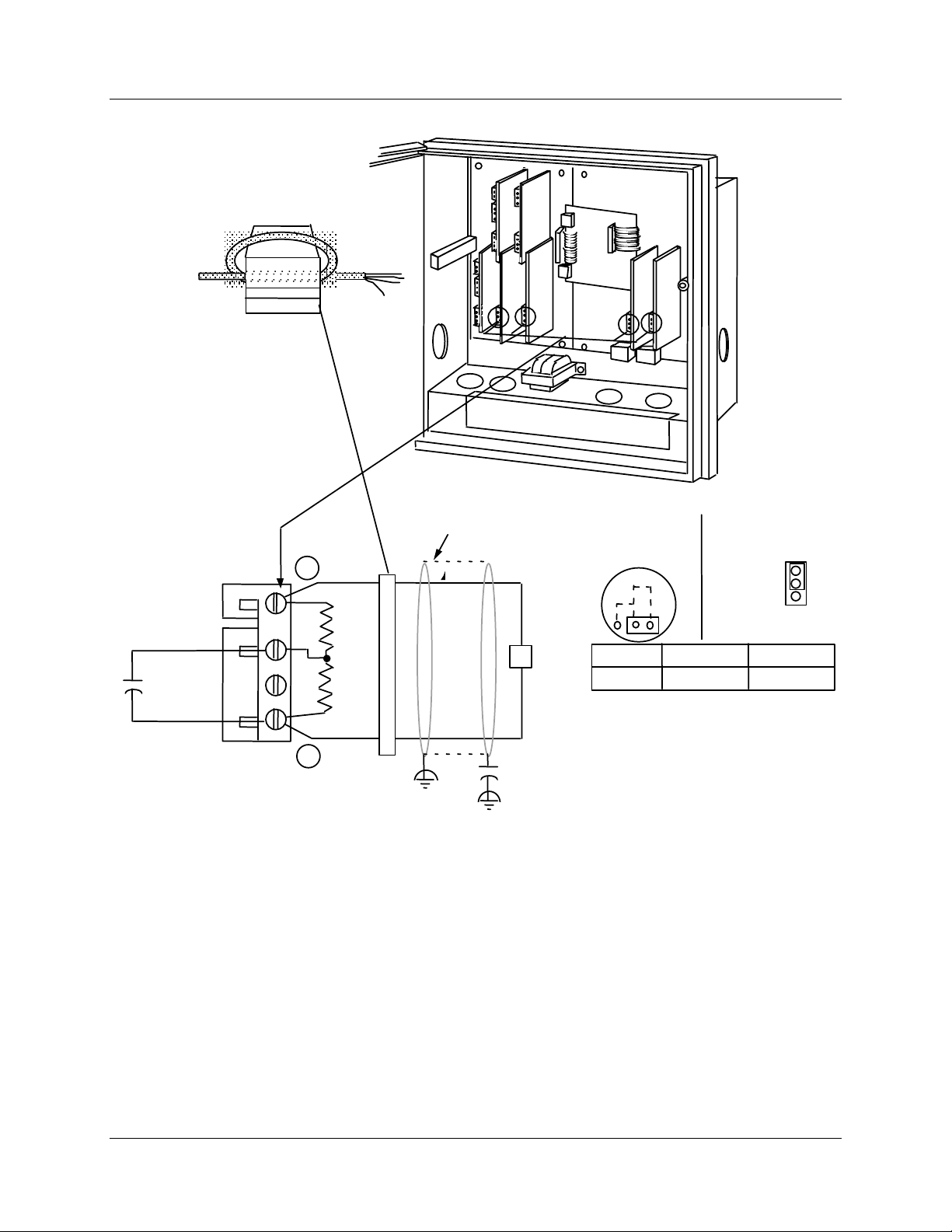
Installation
Input Wiring Procedures
Ferrite Filter
Fair-Rite P/N 0443164151
or equivalent
#4
#3
#2 #1
Required for CE Mark Conformity
Kit Part No. 51197612-502, contains two
ferrite filters; Part No.51197612-508
contains 8 ferrite filters. Install inside of
case. See Figure 2-11.
Capacitor Kit 51197755-001
Install capacitors as shown in figure.
+
100K
.01 µF
Plug J2
100K
_
(modified)
NOTE: Calibrate recorder to achieve stated
accuracy. See Section 7 - Input Calibration.
MA/W1 Jumper
Cable Shield
0-10
Vdc
source
.0047 µF
Capacitor
position on input
board
MA
TYPE W1/MA W3
Linear
Figure 2-15 0-10 Volt dc Input Wiring
W1
21413B
W3 Jumper
Positions
Linear/MA
W1 T/C
T/C
RTD
38 DR4500A Truline Circular Chart Recorder With or Without Control Product Manual Release L
8/02
Page 53

2.7 Output Wiring Procedures
4-20 mA control output wiring
You can wire control output 1 or 2 for 4-20 mA output.
The prerequisites are:
• Model Number - Table 2 = 10, 40, 44, 60, or 66
Refer to Figure 2-16 and follow the procedure in Table 2-15 to wire 4-20 mA control outputs.
Table 2-15 4-20 mA Control Output Wiring
Step Action
1 Open the recorder door. Loosen the captive screw in the chart plate and swing the plate out.
2
Locate connector J1 near the top of the control output #1 or #2 printed circuit board (refer to
Figure 2-16 for location).
3 Remove the unwired plug from J1.
4 Run the output wires through the desired knockout.
Installation
Output Wiring Procedures
5
For CE Mark conformity, install the ferrite filter as shown in Figure 2-11 and the .0047 µF
capacitor as shown in Figure 2-16.
6 Strip insulation from the end of each wire.
7 Loosen the screws in plug J1 terminals and position the plug as you would to plug it into J1.
8
Observing the polarity, insert the wires into the appropriate screw clamps as shown (refer to
Figure 2-16). Tighten the screws to secure the wires.
9 Install the wired plug into J1.
10
Locate jumper position W6/W7 on the bottom left portion of the board. Make sure W7 position
is selected for 4-20 mA output.
11 Repeat steps 2 through 10 for control output #2 printed circuit board as applicable.
TIP
The 4-20 mA output can be used as a retransmission output if it is not used as a control
output.
Release L DR4500A Truline Circular Chart Recorder With or Without Control Product Manual 39
8/02
Page 54
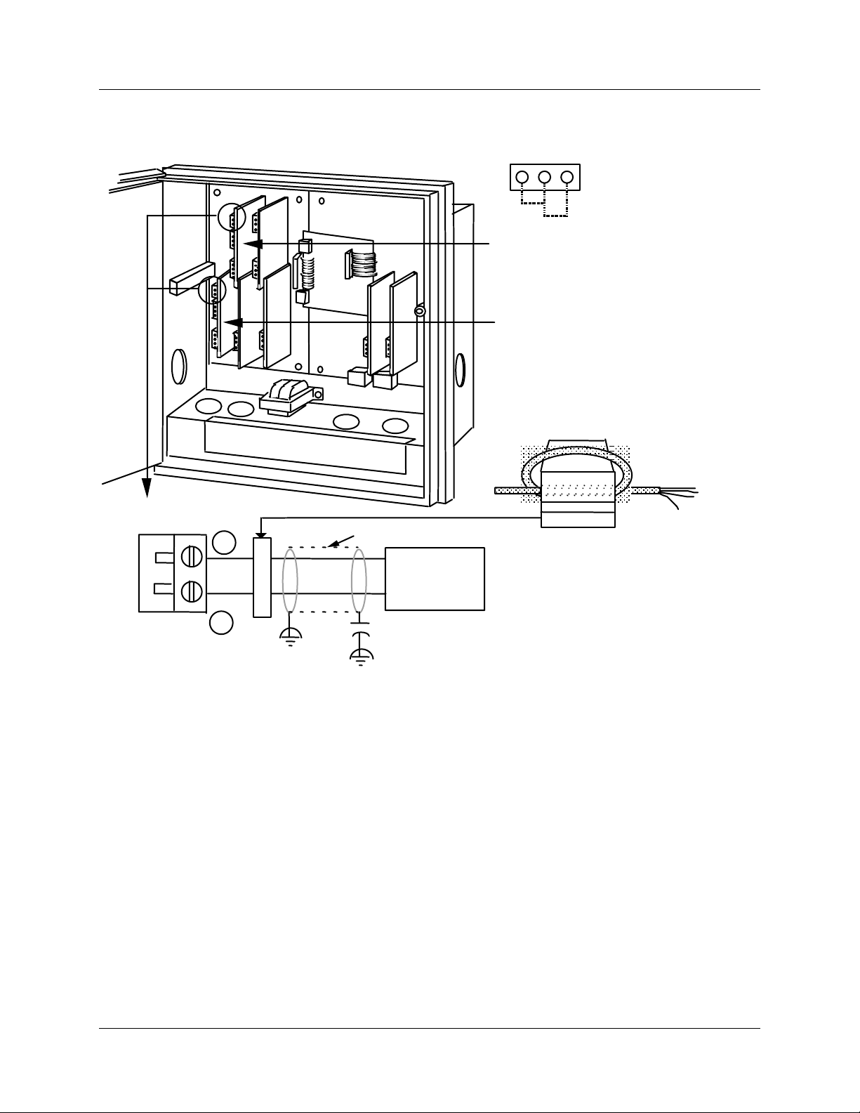
Installation
Output Wiring Procedures
#4
#3
#2 #1
Control Output #1-2 PCB
Current Output Select Jumper
W7 = Relay or
Current Output
W6
W7
Control Output #1 PCB
or
Auxiliary Output #2
Control Output #2 PCB
or
Auxiliary Output #3
Ferrite Filter
21414
4-20 mA
output
Plug J1
+
_
Cable Shield
Controller load
0-1000 ohms
.0047 µF
Capacitor
Fair-Rite P/N 0443164151
or equivalent
Required for CE Mark Conformity
Kit Part No. 51197612-502, contains two
ferrite filters; Part No.51197612-508
contains 8 ferrite filters. Install inside of
case. See Figure 2-11.
Capacitor Kit 51197755-001
Install capacitors as shown in figure.
Figure 2-16 4-20 mA Control Output Wiring (or Aux Out #2 and #3 Wiring)
40 DR4500A Truline Circular Chart Recorder With or Without Control Product Manual Release L
8/02
Page 55

Position proportional or 3-position step control output wiring
You can wire control output 1 or 2 for position proportional or 3 position step output.
The prerequisites are:
• Model Number Key = DR45AT
• Model Number - Table 2 = 10, 40, or 44
Refer to Figure 2-17 and follow the procedure in Table 2-16 to wire position proportional or 3 position step
control outputs.
ATTENTION
Be sure to calibrate the position proportional control output so that the increase and decrease
relays operate properly with respect to the position of the external feedback slidewire. Refer to
Section 8 - Output Calibration in this manual.
Slidewire input is not required for 3 position step control but can be used for motor position indication.
Table 2-16 Position Proportional Control Output Wiring
Step Action
Installation
Output Wiring Procedures
1 Open the recorder door. Loosen the captive screw in the chart plate and swing the plate out.
2
Locate connector J2 and J5 on the control output #1 printed circuit board (refer to Figure 2-17
for location).
3
Locate jumper positions W2/W3 and W4/W5 below connector J5 on the printed circuit board.
Remove plug-in output #1 printed circuit board for better access to the jumpers. Be sure to tag
and remove all the plug connections to the printed circuit board before removing it. Position the
jumpers as shown in Figure 2-17 for desired relay contact action. Locate jumper position
W6/W7 on the bottom left portion of the board. Make sure position W6 is selected for position
proportioning, then reinstall the printed circuit board.
4
Run the feedback slidewire (not required for 3 position step) and motor drive wires through the
desired knockouts.
5 For CE Mark conformity:
• install the ferrite filter as shown in Figure 2-11
• install the shield capacitors as shown in Figure 2-17.
6 Strip insulation from the end of each wire.
7 Loosen the screws in plug J2 terminals and position the plug as you would to plug it into J2.
8
Insert the wires from the motor’s feedback slidewire into the appropriate screw clamps as
shown (refer to Figure 2-17). Tighten the screws to secure the wires.
9 Loosen the screws in plug J5 terminals and position the plug as you would to plug it into J5.
10
Insert the wires for the motor into the appropriate screw clamps as shown (refer to Figure
2-17). Tighten the screws to secure the wires.
11 Install the wired plug into J2 and J5, as applicable.
12 Repeat steps 2 through 11 for Control Output #2 printed circuit board as applicable.
Release L DR4500A Truline Circular Chart Recorder With or Without Control Product Manual 41
8/02
Page 56
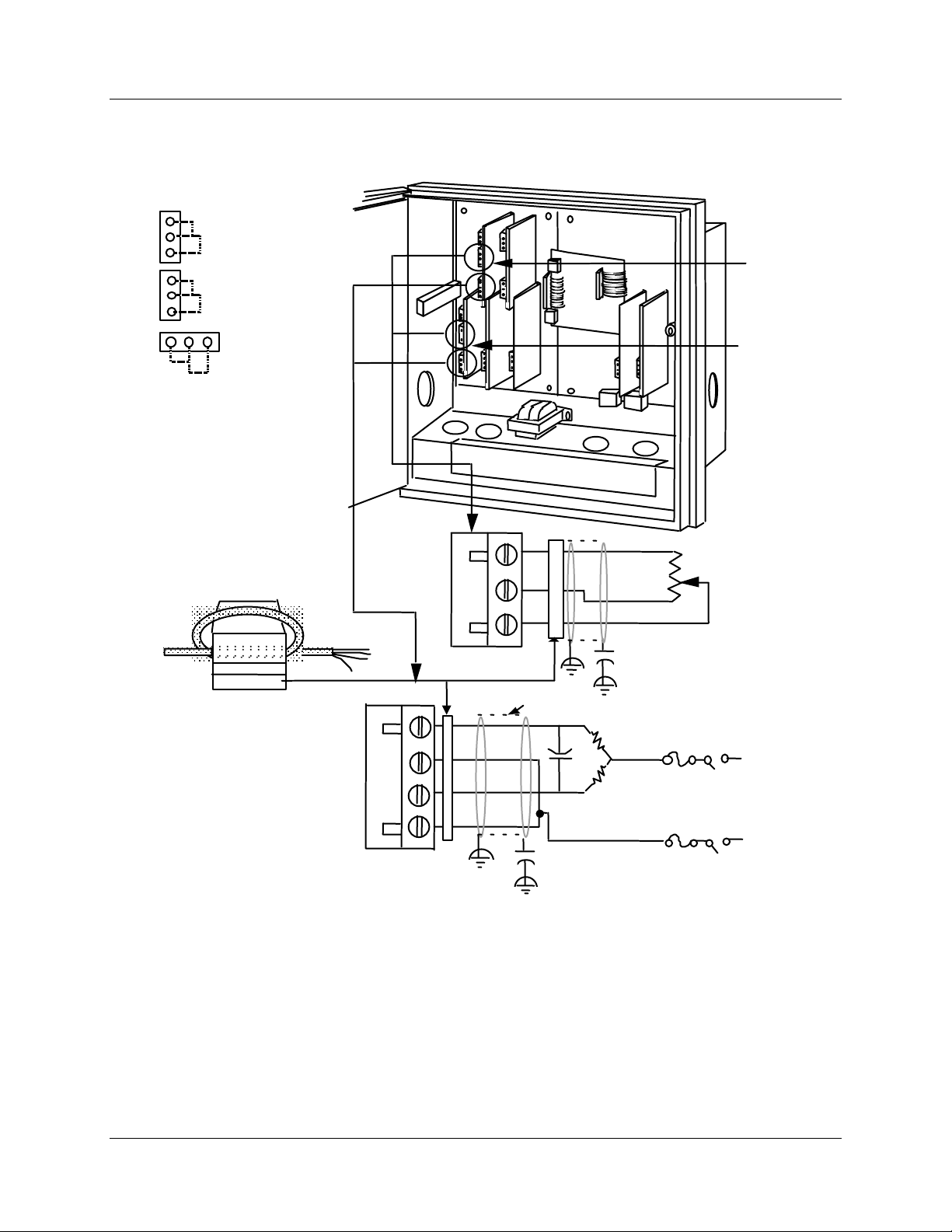
Installation
Output Wiring Procedures
Control output
#1-2 PCB
Relay No. 1
W2
W2 = N.O. contact
W3
W3 = N.C. contact
Relay No. 2
W4
W4 = N.O. contact
W5
W5 = N.C. contact
W6 = Position
W6
W7
Proportional
Output
Ferrite Filter
Fair-Rite P/N 0443164151
or equivalent
Required for CE Mark Conformity
Kit Part No. 51197612-502, contains
two ferrite filters; Part No.
51197612-508 contains 8 ferrite filters.
Install inside of case. See Figure 2-11.
Capacitor Kit 51197755-001
Install capacitors as shown in figure.
Figure 2-17 Position Proportional Control Output or Three Position Step Wiring
Plug J5
Relay 1
Relay 2
#4
Plug J2
#3
1
2
3
Cable Shield
.0047 µF
Capacitor
#2 #1
OPEN
CLOSED
.0047 µF
Capacitor
OPEN (CW)
CLOSED (CCW)
Control
output
#1 PCB
Control
output
#2 PCB
Motor's feedback
slidewire 100
to 1000
(Not required for
Three Position
Step Control)
N
Motor
power
supply
21415
H
42 DR4500A Truline Circular Chart Recorder With or Without Control Product Manual Release L
8/02
Page 57
Relay control output wiring
You can wire control output 1 or 2 for relay output including Time proportional and 3 position step
applications.
The prerequisites are:
• Model Number - Table 2 = 10, 40, 60, 11, 44, 66
Refer to Figure 2-18 and follow the procedure in Table 2-17 to wire relay control outputs.
ATTENTION
Relay #2 is used for time proportional control. Relay 2 can also be used for 3 position step
control (see Figure 2-17).
Step Action
1 Open the recorder door. Loosen the captive screw in the chart plate and swing the plate out.
Installation
Output Wiring Procedures
Table 2-17 Relay Control Output Wiring
2
Locate connector J5 on the control output #1 printed circuit board (refer to Figure 2-18 for
location).
3 Remove the unwired plug from J5.
4
Locate jumper positions W2/W3 and W4/W5 below connector J5 on the printed circuit board.
Remove plug-in output #1 printed circuit board for better access to the jumpers. Be sure to tag
and remove all the plug connections to the printed circuit board before removing it. Position the
jumpers as shown in Figure 2-18 for desired relay contact action. Locate jumper position
W6/W7 on the bottom left portion of the board. Make sure W7 position is selected for relay
control output, then reinstall the printed circuit board.
5 Run the relay load wires through the desired knockouts.
6
For CE Mark conformity:
- install the ferrite filter as shown in Figure 2-11.
- install the shield capacitor as shown in Figure 2-18.
7 Strip insulation from the end of each wire.
8 Loosen the screws in plug J5 terminals and position the plug as you would to plug it into J5.
9
Insert the relay wires and relay power into the appropriate screw clamps for single or duplex
action as shown (refer to Figure 2-18); tighten the screws to secure the wires.
10 Install the wired plug into J5.
11 Repeat steps 2 through 10 for control output #2 printed circuit board as applicable.
Release L DR4500A Truline Circular Chart Recorder With or Without Control Product Manual 43
8/02
Page 58
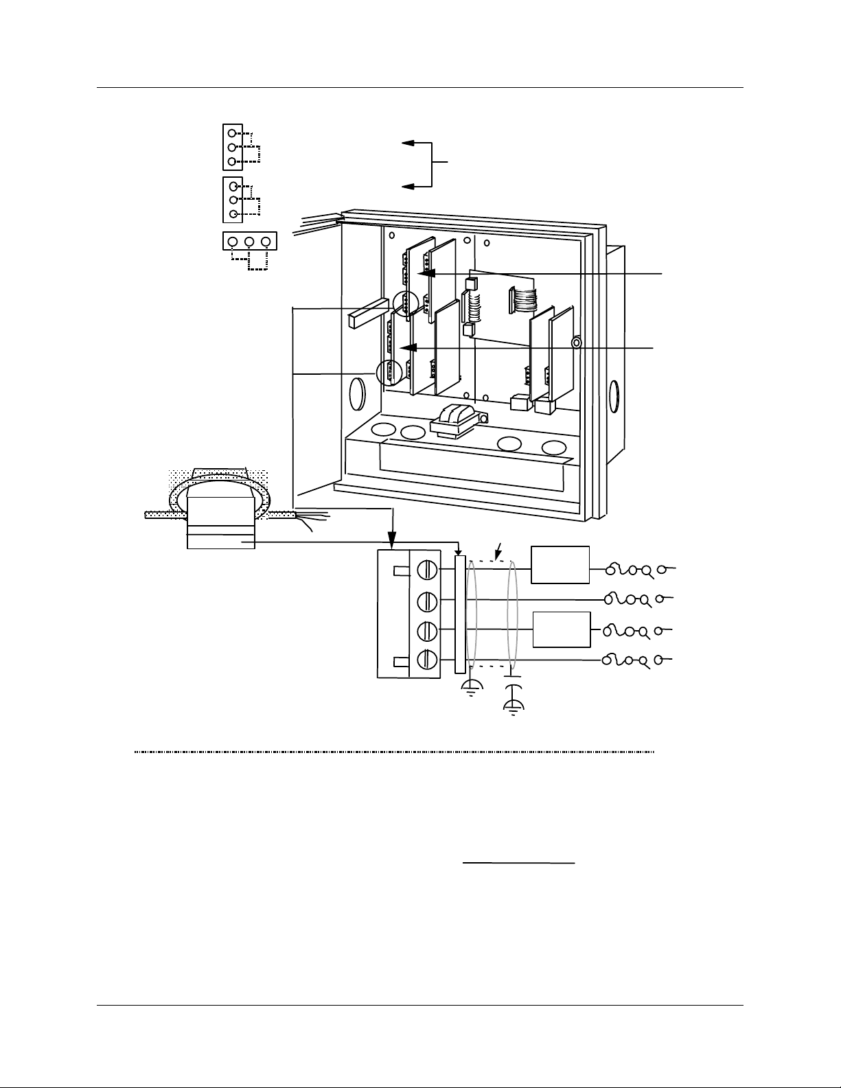
Installation
Output Wiring Procedures
Control
output
#1-2 PCB
Relay No. 1
W2
W2 = N.O. contact
W3
W3 = N.C. contact
Relay No. 2
W4 = N.O. contact
W4
W5 = N.C. contact
W5
Position when shipped
N.O. with power applied
and out indicator light off.
W7 = Relay or
Current Output
W6
W7
Ferrite Filter
Fair-Rite P/N 0443164151
or equivalent
Required for CE Mark Conformity
Kit Part No. 51197612-502, contains two
ferrite filters; Part No.51197612-508
contains 8 ferrite filters. Install inside of
case. See Figure 2-11.
Capacitor Kit 51197755-001
Install capacitors as shown in figure.
*Relay 2 is used for time proportional duplex.
Also used for 3 position step. See Figure 2-17.
#3
#4
Plug J5 (see Notes)
#2 #1
Cable Shield
.0047 µ F
Capacitor
Relay 1
load
Heat
Relay 2
load
Cooling
External Load
power supply
*
Control
output
#1 PCB
Control
output
#2 PCB
N
H
N
H
Notes:
1.
J5 terminals 2 and 4 are the non-switched connections to an SPST relay.
Selectable for normally open or normally closed as required.
2.
This relay supplies a dry contact closure. User must supply appropriate
power connections for his external device.
3.
This relay has a resistive load rating of 5A @ 120 Vac
Load calculation example:
Figure 2-18 Relay Control Output Wiring
44 DR4500A Truline Circular Chart Recorder With or Without Control Product Manual Release L
8/02
Supply voltage
(for example: 115 Vac)
Resistance of customer
controlled device
must equal a
=
number less
than 5 amps
21416
Page 59

2.8 Option Wiring Procedures
Alarm output and digital input wiring
You can wire #1 and #2 Alarm Outputs and Digital Inputs.
The prerequisites are:
• Model Number - Table 3 = XX1
Refer to Figure 2-19 and follow the procedure in Table 2-18 to wire alarm outputs or digital inputs.
The alarm output is a dry contact closure.
Table 2-18 Alarm Output or Digital Input Wiring
Step Action
Open the recorder door. Loosen the captive screw in the chart plate and swing the plate out.
1
Locate connector J3 and J4 on the alarm output/digital input printed circuit board (refer to
2
Figure 2-19 for location).
Remove the unwired plug from J3.
3
Installation
Option Wiring Procedures
Run the digital input wires through the desired knockout.
4
For CE Mark conformity, install the ferrite filter as shown in Figure 2-11.
5
Strip insulation from the end of each wire.
6
Loosen the screws in plug J3 terminals and position the plug as you would to plug it into J3.
7
Insert the wires for the digital inputs into the appropriate screw clamps as shown (refer to
8
Figure 2-19). Note that you can wire the contacts in an
or either contact initiates the configured action. Tighten the screws to secure the wires.
Install the wired plug into J3.
9
10
11
12
13
14
15
16
17
Remove the unwired plug from J4.
Run the alarm output wires through the desired knockout.
For CE Mark conformity:
• install the ferrite filter as shown in Figure 2-11
• install the shield capacitors as shown in Figure 2-19.
Strip insulation from the end of each wire.
Loosen the screws in plug J4 terminals and position the plug as you would to plug it into J4.
Insert the wires for the alarm devices into the appropriate screw clamps as shown (refer to
Figure 2-19). Tighten the screws to secure the wires.
Locate the jumper positions W1/W2 and W3/W4 on the printed circuit board. Reposition the
jumpers as shown in Figure 2-19 for the desired relay control action. The recorder is shipped
with the W1 and W3 in N.C. positions.
Install the wired plug into J4.
and/or fashion, so that both contacts
Release L DR4500A Truline Circular Chart Recorder With or Without Control Product Manual 45
8/02
Page 60
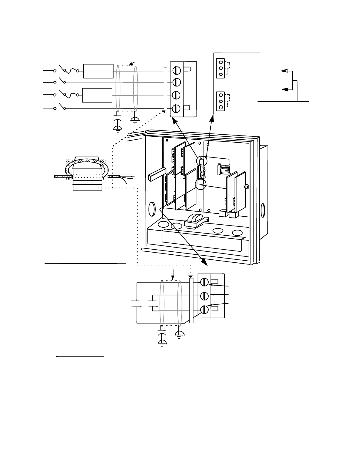
Installation
Option Wiring Procedures
External Load
Power Supply
Alarm #1
Relay Load
Alarm #2
Relay Load
.0047 µF
Capacitor
Ferrite Filter
Fair-Rite P/N 0443164151
Required for CE Mark Conformity
Kit Part No. 51197612-502, contains two
ferrite filters; Part No.51197612-508
contains 8 ferrite filters. Install inside of
case. See Figure 2-11.
Capacitor Kit 51197755-001
Install capacitors as shown in figure.
or equivalent
Cable Shield
Alarm outputs
Plug J4
(see Notes)
#3
#4
W4
Alarm No. 1
W3 = N.C. contact
W4 = N.O. contact
W3
Alarm No. 2
W1 = N.C. contact
W2
W2 = N.O. contact
W1
#2 #1
Position when shipped
N.C. with power off or
Alarm indicator light on.
Notes:
1. J4 terminals 2 and 4 are the nonswitched connections to an
SPST relay. Selectable for
normally open or normally closed
as required.
2. This relay supplies a dry contact
closure. User must supply
appropriate power connections
for his external device.
3. This relay has a resistive load
rating of 1 A @ 120 Vac
Load calculation example:
Supply voltage
(for example: 115 Vac)
Resistance of customer
controlled device
=
Cable Shield
Digital inputs
PIN 3 - 2nd Control Loop + Digital 2
PIN 2 - 1st Control Loop + Digital 1
PIN 1 - Recorder Supplied
Voltage Source
Plug J3
for Digital Inputs
.0047 µF
Capacitor
must equal a
number less
than 1 amps
Figure 2-19 Alarm Output or Digital Input Wiring
21417
46 DR4500A Truline Circular Chart Recorder With or Without Control Product Manual Release L
8/02
Page 61

Additional alarm wiring information
The DR4500 has the ability to provide for Alarm outputs 3, 4, 5, and 6.
Follow the procedures listed below to wire No. 3 and No. 4 Alarm Outputs and No. 5 and No. 6 Alarm
Outputs.
Alarms 3 and 4 output wiring
You can wire #3 and #4 Alarm Outputs.
The prerequisites are:
• Model Number - Model Table 2 = 1X, 4X, 6X*
*If control output is 4-20 mA, then the relays on the control card are available for use as
alarms on all models except DR45AH/AS/AP models.
Refer to Figure 2-20 and follow the procedure in Table 2-19 to wire Alarm 3 and Alarm 4 outputs.
Table 2-19 Alarm 3 and Alarm 4 Output Wiring
Step Action
Installation
Option Wiring Procedures
1 Open the recorder door. Loosen the captive screw in the chart plate and swing the plate out.
2
Locate connector J5 on the 4-20 mA control output printed circuit board to wire relays #3 and
#4. Refer to Figure 2-20 for location.
3 Remove the unwired plug from J5.
4
Locate jumper position W2/W3 and W4/W5 below connector J5 on the printed circuit board.
Note that you may want to remove the plug-in output printed circuit board for better access to
jumpers. Be sure to tag and remove all the plug connections to the printed circuit boards
before removing it. Position the jumpers as shown for the desired relay contact action and
reinstall the printed circuit board.
5 Run the alarm output wires through the desired knockout.
6 For CE Mark conformity:
• install the ferrite filter as shown in Figure 2-11
• install the capacitors as shown in Figure 2-20
7 Strip insulation from the end of each wire.
8 Loosen the screws in plug J5 terminals and position the plug as you would to plug it into J5.
9
Insert the wires for the alarm devices into the appropriate screw clamps as shown. Refer to
Figure 2-20. Tighten the screws to secure the wires.
10 Install the wired plug into J5.
Release L DR4500A Truline Circular Chart Recorder With or Without Control Product Manual 47
8/02
Page 62

Installation
Option Wiring Procedures
Alarms 5 and 6 output wiring
You can wire #5 and #6 Alarm outputs.
The prerequisites are:
• Model Number - Model Table 2 = X1, X4, X6*
*If control output is 4-20 mA, then the relays on the control card are available for use as
alarms on all models except DR45AH/AS/AP models.
Refer to Figure 2-20 and follow the procedure in Table 2-20 to wire Alarm 5 and Alarm 6 outputs.
Step Action
1 Open the recorder door. Loosen the captive screw in the chart plate and swing the plate out.
2
Locate connector J5 on the 4-20 mA control output printed circuit board to wire relays #5 and
#6. Refer to Figure 2-20 for location.
3 Remove the unwired plug from J5.
Table 2-20 Alarm 5 and Alarm 6 Output Wiring
4
Locate jumper position W2/W3 and W4/W5 below connector J5 on the printed circuit board.
Note that you may want to remove the plug-in output printed circuit board for better access to
jumpers. Be sure to tag and remove all the plug connections to the printed circuit boards
before removing it. Position the jumpers as shown for the desired relay contact action and
reinstall the printed circuit board.
5 Run the Alarm output wires through the desired knockout.
6 For CE Mark conformity:
• install the ferrite filter as shown in Figure 2-11
• install the capacitors as shown in Figure 2-20
7 Strip insulation from the end of each wire.
8 Loosen the screws in plug J5 terminals and position the plug as you would to plug it into J5.
9
Insert the wires for the alarm devices into the appropriate screw clamps as shown. Refer to
Figure 2-20. Tighten the screws to secure the wires.
10 Install the wired plug into J5.
48 DR4500A Truline Circular Chart Recorder With or Without Control Product Manual Release L
8/02
Page 63
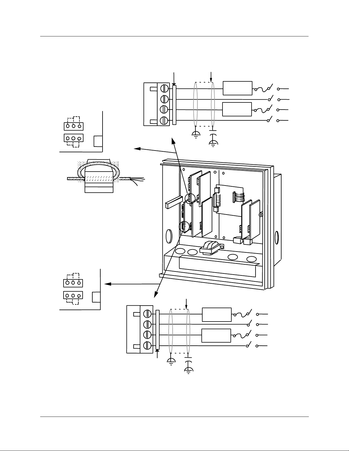
Wiring for alarm outputs #3, 4, 5, and 6
Alarm No. 3
W2 = N.O. contact
W3 = N.C. contact
Alarm No. 4
W4 = N.O. contact
W5 = N.C. contact
W3 W2
Ferrite filter
Cable Shield
Installation
Option Wiring Procedures
External Load
Power Supply
Alarm #3
Relay Load
Alarm #4
Relay Load
4 - 20 mA
control output
and no. 3 & 4
alarm outputs
W5 W4
PCB
Ferrite Filter
Fair-Rite P/N 0443164151
or equivalent
Required for CE Mark Conformity
Kit Part No. 51197612-502, contains two
ferrite filters; Part No.51197612-508
contains 8 ferrite filters. Install inside of
case. See Figure 2-11.
Capacitor Kit 51197755-001
Install capacitors as shown in figure.
No. 5 & 6
Alarm outputs PCB
W3 W2
Plug J5
#4
#3
.0047 µF
Capacitor
#2 #1
21466
External Load
Power Supply
W5 W4
Alarm No. 5
W2 = N.O. contact
Plug J5
Cable Shield
Alarm #5
Relay Load
W3 = N.C. contact
Alarm No. 6
W4 = N.O. contact
Alarm #6
Relay Load
W5 = N.C. contact
Ferrite filter
.0047 µF
Capacitor
Figure 2-20 Alarm outputs #3, 4, 5, and 6 wiring
Release L DR4500A Truline Circular Chart Recorder With or Without Control Product Manual 49
8/02
Page 64

Installation
Option Wiring Procedures
RS485 Modbus communications wiring
RS485 Modbus Communications is an option available on the DR4500A recorder.
The prerequisites are:
• Model Key Number - All models except DR45AH/AP/AS
• Model Number - Table 3 = 3XX or 4XX
Refer to Figure 2-21 and follow the procedure in Table 2-21 to wire the RS485 Modbus communications
option.
Table 2-21 RS485 Modbus Communications Wiring
Step Action
1 Open the recorder door. Loosen the captive screw in the chart plate and swing the plate out.
2
Locate connector J3 on the RS485 Modbus communications option printed circuit board (refer
to Figure 2-21 for location).
3 Remove the unwired plug from J3.
4 Run the communications option wires through the desired knockout.
5 For CE Mark conformity
• Install the ferrite filter as shown in Figure 2-11.
• Refer to Figure 2-21 for shield information.
6 Strip insulation from the end of each wire.
7 Loosen the screws in plug J3 terminals and position the plug as you would to plug it into J3.
8
Insert the wires for the communications option into the appropriate screw clamps as shown
(refer to Figure 2-22). Tighten the screws to secure the wires.
9 Install the wired plug J3 into J3 connector on the communications board.
REFERENCE
Refer to documents 51-52-25-66 and 51-52-25-69 for a complete description of RS485
Modbus Communications Option.
50 DR4500A Truline Circular Chart Recorder With or Without Control Product Manual Release L
8/02
Page 65
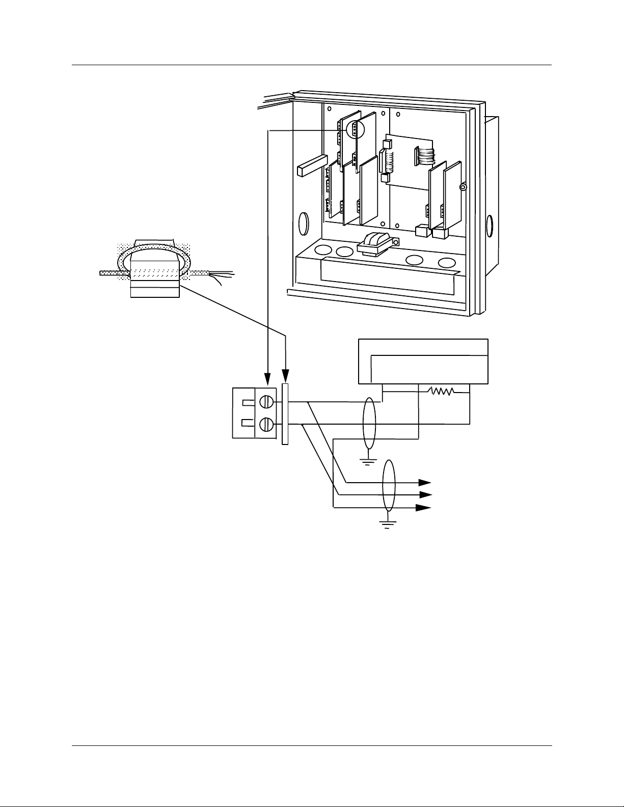
Ferrite Filter
Fair-Rite P/N 0443164151
or equivalent
Required for CE Mark Conformity— Kit
supplied Part No. 51197612-502,
contains two ferrite filters. More than one
kit may be supplied. Install inside of case.
See Figure 2-11.
Communication wire must be Alpha
XTRA Guard I Cable (Alpha P/N 5121C)
Plug J3
See
Note 2
#3
#4
Communications master
Tx+/
Rx+
SHLD
See
Note 1
Installation
Option Wiring Procedures
#2 #1
Tx–/
Rx–
120 Ohm
Resistor
Place 120 ohm resistor on
last device, between Tx+/Rx+
and Tx–/Rx–.
Notes:
1. The shield of the RS485 Modbus Communications cable is not
connected at the recorder end and should not extend into the
recorder enclosure. The shield of the communication cable
should be connected to earth ground at the farthest end on the cable.
2. For non-CE Mark applications, use shielded twisted pair cables
(Belden 4271 Twinax or equivalent).
Optional communication
communications
instruments
(Maximum 15)
21418G
Figure 2-21 RS485 Modbus Communications Wiring
Release L DR4500A Truline Circular Chart Recorder With or Without Control Product Manual 51
8/02
To other
Page 66
Installation
Option Wiring Procedures
4-20 mA auxiliary output wiring
You can wire an auxiliary output for 4–20 mA.
The prerequisites are:
• Model Number - Table 3 = 1XX or 4XX
Refer to Figure 2-22 and follow the procedure in Table 2-22 to wire 4–20 mA auxiliary output.
Step Action
1 Open the recorder door. Loosen the captive screw in the chart plate and swing the plate out.
2
Locate connector J2 near the bottom of the auxiliary output printed circuit board (refer to
Figure 2-22 for location).
3 Remove the unwired plug from J2.
4 Run the output wires through the desired knockout.
5 For CE Mark conformity, install the ferrite filter as shown in Figure 2-11.
Table 2-22 4-20 mA Auxiliary Output Wiring
6 Strip insulation from the end of each wire.
7 Loosen the screws in plug J2 terminals and position the plug as you would to plug it into J2.
8
Observing the polarity, insert the wires into the appropriate screw clamps as shown (refer to
Figure 2-22). Tighten the screws to secure the wires.
9 Install the wired plug into J2.
ATTENTION
Be sure that the 4-20 mA auxiliary output is aligned. Refer to Subsection 8.4 Auxiliary Output
Calibration.
TIP
The 4-20 mA output on the control output board can also be set up for an Auxiliary
retransmission output if it is not being used for a control output. This requires model selection
option Table II = 10, 40, 44, 60, 66.
TIP
Auxiliary output 2 and Auxiliary output 3 use Control current output 1 and Control current
output 2 if Control “OUT ALG” is not set to “CURRENT”.
and #3 wiring.
Refer to Figure 2-16 for Aux Out #2
52 DR4500A Truline Circular Chart Recorder With or Without Control Product Manual Release L
8/02
Page 67
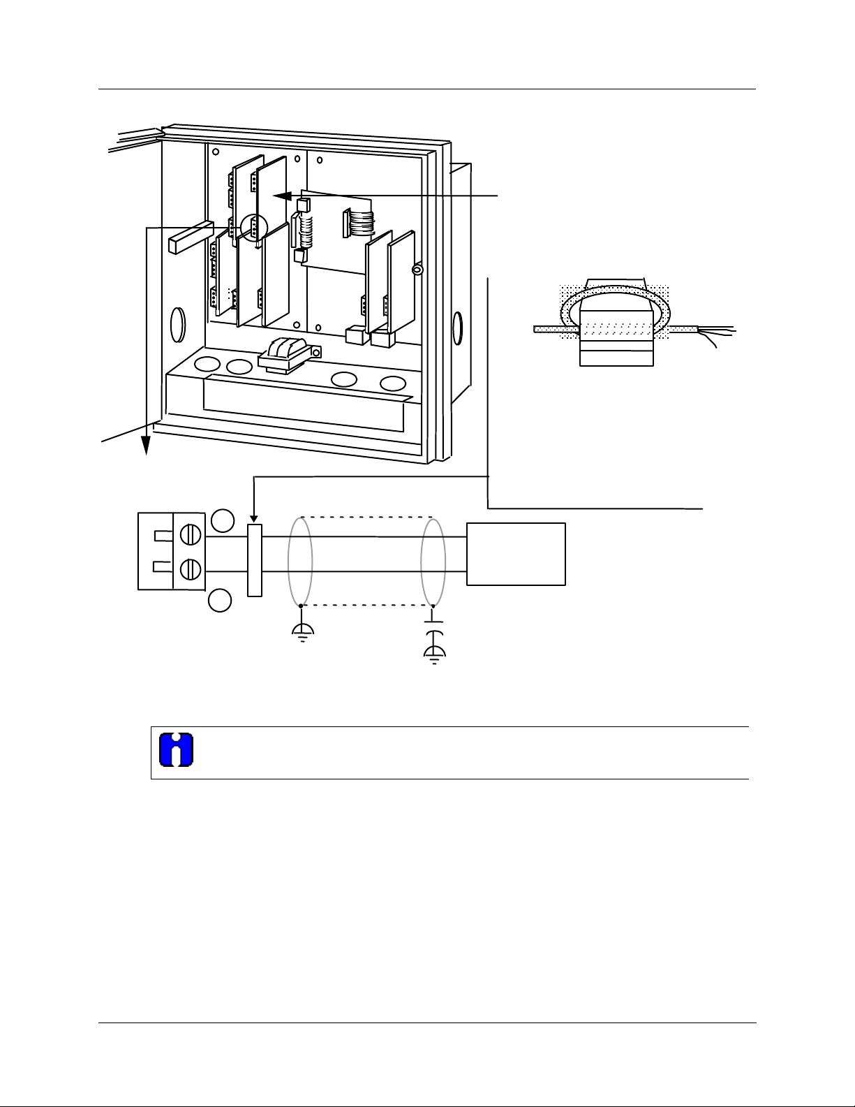
4-20 mA
auxiliary
output
Installation
Option Wiring Procedures
Auxiliary
Output
PCB
#3
#4
#2 #1
Required for CE Mark Conformity
Kit Part No. 51197612-502, contains two
ferrite filters; Part No.51197612-508
contains 8 ferrite filters. Install inside of
case. See Figure 2-11.
Capacitor Kit 51197755-001
Install capacitors as shown in figure.
Ferrite Filter
Fair-Rite P/N 0443164151
or equivalent
+
Controller load
0-1000 ohms
_
Plug J2
.0047 µF Capacitor
22841G
Figure 2-22 4-20 mA Auxiliary Output #1 Wiring
ATTENTION
Refer to Figure 2-16 for Auxiliary Output 2 and Auxiliary Output 3 wiring.
Release L DR4500A Truline Circular Chart Recorder With or Without Control Product Manual 53
8/02
Page 68
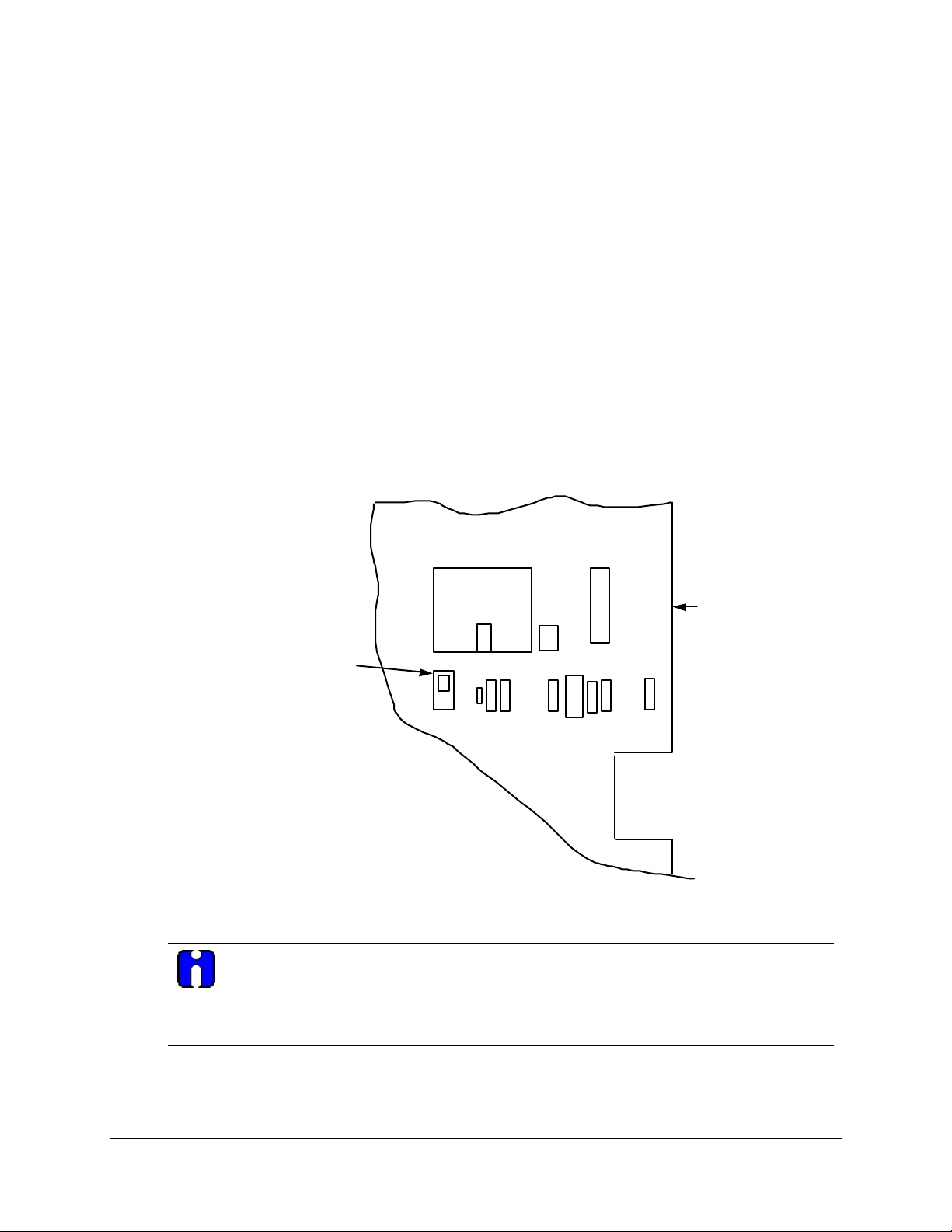
Installation
Lockout Switch Configuration
2.9 Lockout Switch Configuration
Introduction
The configuration can be locked using S1 switch located next to the microprocessor U17 on the main
printed circuit board.
Restrictions based on lockout switch position
Figure 2-23 shows the location of the S1 lockout switch on the main printed circuit board.
When the lockout switch is OFF (Down—Configure):
• You can view and change all applicable operating parameters as described in Section 4 –
Configuration Parameter Definitions.
When the lockout switch is ON (Up—Locked):
• Most parameters for the recorder are locked and the parameters may not be changed except for
Tuning 1 and Tuning 2 parameters and adjustments to time/date/day/year.
Main Printed
U17
J17
U19
Wiring Board
(Right Side)
S1 Lockout Switch
UP (ON) Locked
DOWN (OFF) Configure
S1
C50
R42
R43
R45
Y2
C56
C55
R47
22709
Figure 2-23 S1 Lockout Switch Location
ATTENTION
Lockout can also be configured under set up group “LOCKOUT”. See Subsection 3.21.
This feature also includes the special screw and plate that provide the lead seal capability for
sealing the chart plate. This feature is normally used with DR45AH model recorders.
54 DR4500A Truline Circular Chart Recorder With or Without Control Product Manual Release L
8/02
Page 69

3.1 Overview
Introduction
Configuration is a dedicated operation where you use straightforward keystroke sequences to select and
establish (configure) pertinent control data best suited for your application.
What’s in this section?
The table below lists the topics that are covered in this section.
3.1 Overview 55
3.2 Configuration Prompts 57
3.3 How to Get Started 60
3.4 Configuration Tips 61
3.5 Configuration Procedure 62
3.6 Input Set Up Group 64
3.7 Pen Set Up Group 66
3.8 Chart Set Up Group 67
3.9 Time Set Up Group 69
3.10 Totalizer Set Up Group 70
3.11 Input Algorithm Set Up Group 72
3.12 Control Set Up Group 73
3.13 Tuning Parameters Set Up Group 75
3.14 SP Ramp Set Up Group 76
3.15 Timer Set Up Group 77
3.16 Alarms Set Up Group 78
3.17 Auxiliary Output Set Up Group 80
3.18 Modbus Communications Set Up Group 81
3.19 Options Set Up Group 82
3.20 Event Message 83
3.21 Lockout Set Up Group 86
3.22 Adjust Printing 87
3.23 Configuration Record Sheet 88
3. Configuration
Topic See Page
Release L DR4500A Truline Circular Chart Recorder With or Without Control Product Manual 55
8/02
Page 70

Configuration
Overview
Prompts
To assist you in the configuration process, there are prompts that appear in the upper and lower displays.
These prompts let you know what group of configuration data (set up prompts) you are working with and
also the specific parameters (function prompts) associated with each group.
Figure 3-1 shows an overview of the prompt hierarchy.
56 DR4500A Truline Circular Chart Recorder With or Without Control Product Manual Release L
8/02
Page 71
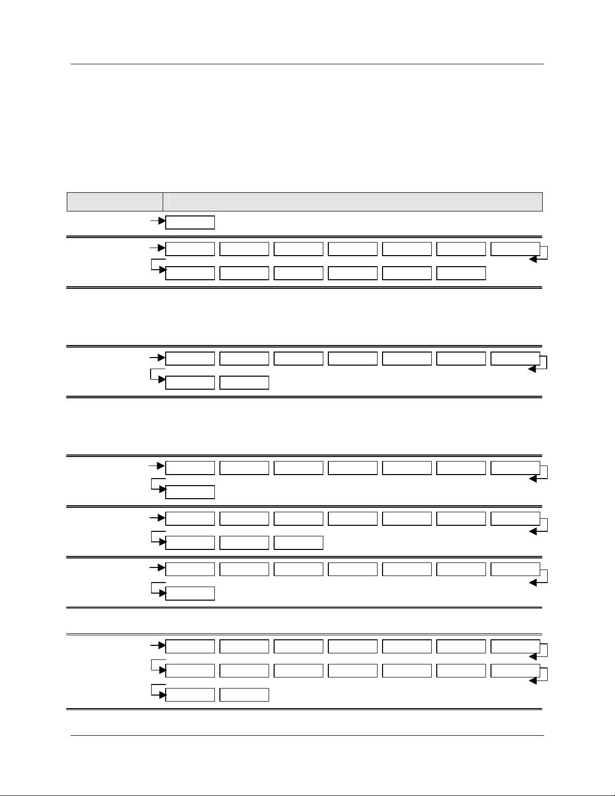
3.2 Configuration Prompts
Diagram: prompt hierarchy
Figure 3-1 shows an overview of the DR4500A Set Up prompts and their associated Function prompt - read
from left to right.
Figure 3-1 DR4500A Prompt Hierarchy
Set Up Group Function Prompts
Configuration
Configuration Prompts
FO RESET
INPUT 1
INPUT 2
INPUT 3
INPUT 4
PEN 1
PEN 2
PEN 3
PEN 4
CHART
RESET FO
ENABLE DECIMAL UNITS ENGUNITS IN1 TYPE XMITTER IN1 HI
IN1 LO CUTOFF 1 INPTCOMP FILTER1 BURNOUT EMISSIV
Same as INPUT 1
ENABLE PEN 1 IN CHART1HI CHART1LO PEN1ON PEN1OFF MAJORDIV
MINORDIV RNG1TAG
Same as PEN 1
CHRTSPD HOUR/REV TIME DIV MINORDIV CONTINUE CHARTNAM HEADER
REM CHRT
Only with key number DR45AR, see Appendix A
TIME
TOTAL 1
TOTAL 2
INP ALG
Release L DR4500A Truline Circular Chart Recorder With or Without Control Product Manual 57
8/02
MINUTES HOURS DAY MONTH YEAR DAY WAKE MIN
WAKE HR WAKE DAY WAKE MON
(Value) RSET TOT TOTAL 1 TOTAL EU RATE SCALER RSETABLE
INHIBIT
Same as TOTAL 1
INP ALG COEFF PV HIGH PV LOW RATIO A BIAS A RATIO B
BIAS B RATIO C BIAS C POLYNOM C0 VALUE C2x10-1 C3x10-3
C4x10-5 C5x10-7
Page 72
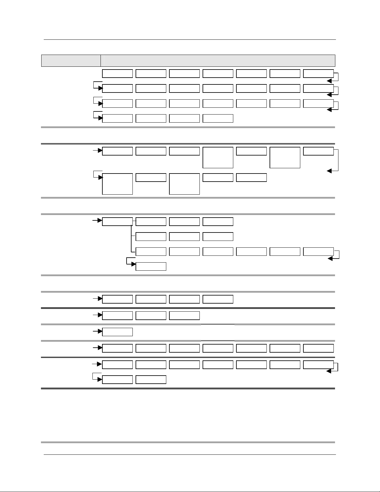
Configuration
Configuration Prompts
Set Up Group Function Prompts
CONTROL 1
CONTROL 2
TUNING 1
TUNING 2
SP RAMP1
ENABLE PID SETS SW VALUE SP SOURC RATIO BIAS SP TRACK
POWER UP PWR OUT SP HILIM SP LOLIM ACTION OUT HILIM OUT LOLIM
DROPOFF DEADBAND OUT HYST FAILSAFE REM SW MAN KEY PBorGAIN
MINorRPM CONT1ALG OUT1ALG 4-20 RNG
Same as CONTROL 1
FUZZY ACCUTUNE AT ERR
PROP BD2
or
GAIN 2
Same as TUNING 1
ENABLE SP RAMP TIME MIN FINAL SP
RATE2MIN
SP RATE EU/HR UP EU/HR DN
SP PROG RECYCLES SOAK DEV PROFILE STATE RECOVERY
RSET2MIN
or
RSET2RPM
PROP BD
or
GAIN
CYC SEC CYC2SEC
RATE MIN
RSET MIN
or
RSET RPM
MAN RSET
SP RAMP2
PROFILES
SPP SEGS
SPP EVNT
TIMER
ALARM 1
ALARM 2
ALARM 3
ALARM 4
ALARM 5
ALARM 6
Same as SP RAMP1
PRx STRT PRx END RAMPUNIT SYNC 1+2
SEGxRAMP SEGx SP SEGxTIME
SEGx EV
TIMER PERIOD START LDISPLAY RSET ON-TIME INCRMENT
A1S1 VAL A1S2 VAL A1S1TYPE A1S2TYPE A1S1 H L A1S1SCAL A1S2 H L
A1S2SCAL AL1 HYST
Same as ALARM 1
PROG END
58 DR4500A Truline Circular Chart Recorder With or Without Control Product Manual Release L
8/02
Page 73
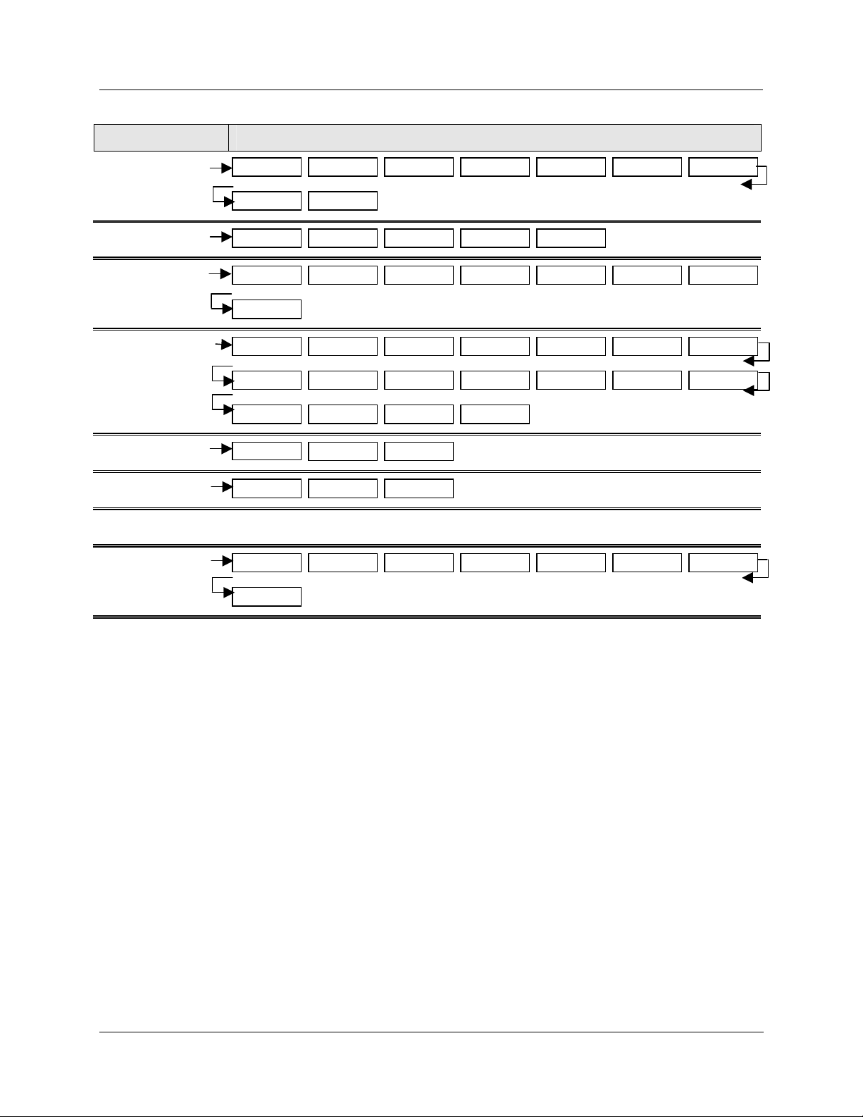
Set Up Group Function Prompts
Configuration
Configuration Prompts
AUX OUT
COMM
OPTIONS
EVNT MSG
LOCKOUT
ADJUST
CALIB
STATUS
AUX OUT 4 mA VAL 20mA VAL AUX OUT 2 4 mA VAL 20mA VAL AUX OUT 3
4mA VAL 20 mA VAL
ComSTATE Com ADDR BAUD XMT DLAY DBL BYTE
REJ FREQ HF REJ RELHUMID ATMPRES DEVIATION DEVSETPT SCROLL
GRANDTOT
EVENT 1 MESSAGE1 POSITION1 EVENT 2 MESSAGE2 POSITION2 EVENT 3
MESSAGE3 POSITION3 EVENT 4 MESSAGE4 POSITION4 EVENT 5 MESSAGE5
POSITION5 EVENT 6 MESSAGE6 POSITION6
PASSWORD
TRACE LN GRID LN PEN TYPE
For field calibration—see Calibration section of manual
VERSION FAILSAFE* RAM TEST CONFTEST CAL TEST COMMTEST FACT CRC
If key number is DR45AR, see Appendix A for Fo calculation prompts.
LOCKOUT CHANGE
BATTERY
*Displayed on test failure only
Release L DR4500A Truline Circular Chart Recorder With or Without Control Product Manual 59
8/02
Page 74

Configuration
How To Get Started
3.3 How To Get Started
Read the configuration tips
Read Subsection 3.4 Configuration Tips which will help you to easily and quickly configure your recorder.
Read configuration procedure
Read Subsection 3.5 Configuration Procedure which tells you how to access the Set Up groups, and the
function parameters within each of these groups that are shown in the Prompt Hierarchy in Figure 3-1.
Set Up groups
The Set Up groups and function parameters are listed in the order of their appearance. The list includes the
name of the prompt, the range of setting or selections available, and the factory setting. It allows you to
quickly find a parameter and obtain the available range or selection you require.
Parameter explanations or definitions
If you need a detailed explanation of any prompt listed, refer to Section 4 – Configuration Parameter
Definitions. This section lists the set up and function prompts, the selections or range of settings that you
can make for each, plus a detailed explanation or definition of each parameter.
Configuration record sheet
Located in Subsection 3.23 is a Configuration Record Sheet. When you make your configuration selections,
record them on this sheet. Then you will have a record of how the recorder was configured.
Set up the recorder in this order:
• Inputs (Display will be correct)
• Pens (Trace will agree with display)
• Chart
• Alarms
• Control
• Tuning
• Other functions as needed
60 DR4500A Truline Circular Chart Recorder With or Without Control Product Manual Release L
8/02
Page 75
3.4 Configuration Tips
Introduction
Listed below in Table 3-1 are some tips that will help you enter the configuration data more quickly.
Function Tip
Configuration
Configuration Tips
Table 3-1 Configuration Tips
Displaying groups
Displaying
functions
Scrolling
Changing values
quickly
Restoring to the
original value
Exiting Set Up mode
Timing out from Set
Up mode
Use the SET UP key to display the Set Up groups. The group titles are listed in
this section in the order that they appear in the recorder.
Use the FUNC key to display the individual parameters under each group. The
prompts are listed in the order of their appearance in each group.
To get to a Set Up group prompt more quickly, hold the SET UP key in. To get
to a function prompt more quickly, hold the FUNC key in. The display will scroll
through the parameters.
ATTENTION
UP or FUNC key is held in. Also, [▲] [▼] keys will move group prompts
forward or backward at a rate twice as fast.
When Changing the value of a parameter, you can adjust a more significant
digit in the upper display by holding in one key [▲] or [▼] , and pressing the
other [▲] or [▼] at the same time.
• The adjustment will move one digit to the left.
• Press the key again and you will move one more digit to the left.
When you change the value or selection of a parameter while in Set Up mode
and decide not to enter it, press RUN/HOLD once, the original value or
selection will be recalled.
To exit Set Up mode, press the LOWR DISP key. This returns the display to
the same state it was in immediately preceding entry into the Set Up mode.
If you are in Set Up mode and do not press any keys for one minute, the
recorder will time out and revert to the mode and display that was being used
prior to entry into Set Up mode.
The prompting scrolls at a rate of 2/3 seconds when the SET
Key error
When a key is pressed and the prompt “KEY ERROR” appears in the lower
display, it will be for one of the following reasons:
• parameter not available
• not in Set Up mode, press SET UP key first
• key malfunction, do keyboard test (operation)
• individual key locked out
Release L DR4500A Truline Circular Chart Recorder With or Without Control Product Manual 61
8/02
Page 76

Configuration
Configuration Procedure
3.5 Configuration Procedure
Introduction
• Each of the Set Up groups and their functions are preconfigured at the factory.
• The factory settings are shown in the Set Up group tables that follow this procedure.
• If you want to change any of these selections or values, follow the procedure in Table 3-2. This
procedure tells you the keys to press to get to any Set Up group and any associated Function parameter
prompt.
• If you need a detailed explanation of any prompt, refer to Section 4 – Configuration Parameter
Definitions.
Procedure
Follow the procedure listed in Table 3-2 to access the Set Up groups and Function prompts.
TIP
The prompting scrolls at a rate of 2/3 seconds when the SET UP or FUNC key is held in. Also,
[▲] [▼] keys will move group prompts forward or backward at a rate twice as fast.
Table 3-2 Configuration Procedure
Step Operation Press Result
1 Select Set Up mode SET
UP
2 Select any Set Up group SET
UP
3
4
Select a Function
parameter
Select other Function
parameters
FUNC
FUNC
Upper Display: SET UP—Lets you know you are in the
configuration mode and a Set Up group title is being
displayed in the lower display.
Lower Display: INPUT 1—This is the first Set Up group
title.
• Successive presses of the SET UP key will
sequentially display the other Set Up group titles
shown in the prompt hierarchy in Figure 3-1.
• You can also use the [▲] [▼] keys to scan the Set Up
groups in both directions.
• Stop at the Set Up group title which describes the
group of parameters you want to configure. Then
proceed to the next step.
Upper Display: Shows the current value or selection for
the first function prompt of the particular Set Up group
that you have selected (EXAMPLE: ENABLE/DISABLE).
Lower Display:—Depends on what is selected in Set Up
group. Shows the first function prompt within that Set Up
group. Example: “INPUT 1”
• Successive presses of the FUNC key will sequentially
display the other function prompts of the Set Up group
you have selected.
• Stop at the function prompt that you want to change,
then proceed to the next step.
62 DR4500A Truline Circular Chart Recorder With or Without Control Product Manual Release L
8/02
Page 77

Configuration Procedure
Step Operation Press Result
Configuration
5
6 Enter the value or selection
Change the value or
selection
▲ or ▼
FUNC
7 Exit configuration LOWR
or
SET
UP
DISP
• These keys increment or decrement the value or
selection that appears for the function prompt you have
selected.
• See Subsection 3.4 Configuration Tips for instructions
to increase or decrease value quickly.
• Change the value or selection to meet your needs.
• If the display flashes, you are trying to make an
unacceptable entry.
• This key selects another function prompt.
• This key selects another Set Up group.
The value or selection you have made will be entered into
memory after another key is pressed.
This exits configuration mode and returns the recorder to
the same state it was in immediately preceding entry into
the Set Up mode. It stores any changes you have made.
Release L DR4500A Truline Circular Chart Recorder With or Without Control Product Manual 63
8/02
Page 78

Configuration
Input Set Up Group
3.6 Input Set Up Group
Introduction
This data deals with various parameters required to configure input 1, input 2, input 3, or input 4.
Function prompts
Table 3-3 lists all the function prompts in the “INPUT 1” Set Up group. Repeat the process for each input
you want to set up.
• Press the SET UP key until INPUT 2, INPUT 3, or INPUT 4 appears in the display.
Function Prompt
Lower Display
Function Name
Table 3-3 Input Group Function Prompts
Selections or Range of Setting
Upper Display
Factory
Setting
INPUT 1
DECIMAL
UNITS
ENGUNITS
IN1 TYPE
Input 1 Actuation
Decimal Point Location
Temperature Units
Engineering Units
Input 1 Actuation Type
DISABL
ENABLE
XXXX None
XXX.X One
XX.XX Two
X.XXX Three
DEG F
DEG C
XXXXX (make selection at prompt
"ENGUNITS")
0 to 9
A to Z
+
–
\
(blank)
B TC W TC H
E TC H W TC L
E TC L 100 PT
J TC H 200 HI*
J TC L 200 LO*
K TC H 500 PT
K TC L 100 RH
NNM TC 4-20 mA
NIC TC 0-10 mV
R TC 10-50m
S TC 0-5 V
T TC H 0-10 V
T TC L RADIAM
ENABLE
XXX.X
DEG F
100 PT
or
0-5 V
with Control
*DR45AR only
64 DR4500A Truline Circular Chart Recorder With or Without Control Product Manual Release L
8/02
Page 79

Configuration
Input Set Up Group
Function Prompt
Lower Display
XMITTER
IN1 HI
IN1 LO
CUTOFF 1
INPTCOMP
FILTER 1
BURNOUT
Function Name
Transmitter Characterization
Input 1 High Range Value
(linear inputs only)
Input 1 Low Range Value
(linear inputs only)
Low Flow Cutoff Selection 0 to 100 % of input range 0
Input Compensation –999.9 to 9999. 0
Input 1 Filter 0 to 120 seconds 0
Burnout Protection
Selections or Range of Setting
Upper Display
B TC T TC H
E TC H T TC L
E TC L W TC H
J TC H W TC L
J TC L 100 PT
K TC H 500 PT
K TC L 100 RH
NNM TC H LINEAR*
NIC TC SQROOT*
R TC
S TC
*Set “IN1HI” and “IN1LO”
–999.0 to 9999.
in engineering units
–999.0 to 9999.
in engineering units
NONE
UP
DOWN
Factory
Setting
Linear
900
-300
UP
EMISSIV
Emissivity .01 to 1.00 .01
Repeat this procedure for INPUT 2, INPUT 3, and INPUT 4.
Release L DR4500A Truline Circular Chart Recorder With or Without Control Product Manual 65
8/02
Page 80

Configuration
Pen Set Up Group
3.7 Pen Set Up Group
Introduction
The functions listed in this group deal with how to configure pen #1, pen #2, pen #3, or pen #4. The
procedure for configuring each pen is the same. The prompts shown in Table 3-4 show PEN 1.
• Repeat the process for each pen you want to set up.
• Press the SET UP key until PEN 2, PEN 3, or PEN 4 appears in the display.
Function prompts
Table 3-4 lists all the function prompts in the PEN Set Up groups.
Table 3-4 Pen 1, 2, 3, 4 Group Function Prompts
Function Prompt
Lower Display
Function Name
Selections or Range of Setting
Upper Display
Factory
Setting
PEN 1
(or PEN 2, PEN 3,
PEN 4)
PEN1IN
(or PEN2IN,
PEN3IN, PEN4IN)
CHART1HI
(or CHART2HI,
CHART3HI,
CHART4HI)
CHART1LO
(or CHART2LO,
CHART3LO,
CHART4LO)
PEN1ON
(or PEN2ON,
PEN3ON,
PEN4ON)
PEN1OFF
(or PEN2OFF,
PEN3OFF,
PEN4OFF)
MAJORDIV
Pen Record ENABLE
DISABL
Pen Input INPUT1 RH SETPT2
INPUT2 OUTPT1 DGTL1
INPUT3 OUTPT2 DGTL2
INPUT4 SETPT1 PV1
Chart High Range Value –999.0 to 9999 302.0
Chart Low Range Value –999.0 to 9999 292.0
Pen Chart Position for ON
Event
Pen Chart Position for OFF
Event
Major Chart Divisions 2 to 10 10
0 to 100 % 91.0
0 to 100 % 93.0
ENABLE
INPUT 1
MINORDIV
RNG1TAG
Minor Chart Division 2 to 10 10
Range 1 Tag Name 0 to 9
A to Z
+
–
/
(blank)
RNG 1
Repeat this procedure for PEN 2, PEN 3, and PEN 4.
66 DR4500A Truline Circular Chart Recorder With or Without Control Product Manual Release L
8/02
Page 81

3.8 Chart Set Up Group
Introduction
The functions listed in this group deal with the parameters that must be set to assure proper chart function.
CAUTION
Before making any configuration changes to the “Chart” Set Up group, place the recorder in
“Chart Hold”. Press the CHART key to stop the chart rotation. Press again after configuration
entry is made.
Function prompts
Table 3-5 lists all the function prompts in the “Chart” Set Up group.
Table 3-5 Chart Group Function Prompts
Function Prompt
Lower Display
Function Name
Selections or Range of Setting
Upper Display
Configuration
Chart Set Up Group
Factory
Setting
CHRTSPD
HOUR/REV
TIME DIV
MINORDIV
CONTINUE
CHARTNAM
HEADER
Chart Speed Selection
Hours per Revolution
(appears only if "XHR" is
selected above)
Time Division 8 to 24 time periods 24
Minor Time Division
Continue Chart Rotation
Chart Name
Header for Chart
8HR
12HR
24HR
7DAYS
XHR (See prompt "HOUR/REV")
6 to 744 (12 hrs for abrasion resistant pen)
NOTE: Below 8 hrs chart speed (24 hrs chart
speed with abrasion resistant pen), printing
may be degraded.
Four
Eight
YES
NO
0 to 9
A to Z
+
–
/
(blank)
YES
NO
XHR
12
Four
NO
TRULIN
NO
Release L DR4500A Truline Circular Chart Recorder With or Without Control Product Manual 67
8/02
Page 82

Configuration
Chart Set Up Group
Function Prompt
Lower Display
REM CHRT
Function Name
Remote Chart Activation
Selections or Range of Setting
Upper Display
NONE
EXT SW1
EXT SW2
ALARM 1
ALARM 2
TIME (See “WAKE MIN”, “WAKE HOUR”,
“WAKE DAY”, “WAKE MON” in Time Set Up
group.)
ALARM 3
ALARM 4
ALARM 5
ALARM 6
Factory
Setting
NONE
68 DR4500A Truline Circular Chart Recorder With or Without Control Product Manual Release L
8/02
Page 83

3.9 Time Set Up Group
Introduction
The functions listed in this group deal with the parameters that let you configure the real time that will
appear on the chart.
Function prompts
Table 3-6 lists all the function prompts in the “Time” Set Up group.
Function Prompt
Lower Display
Function Name
Table 3-6 Time Group Function Prompts
Selections or Range of Setting
Upper Display
Configuration
Time Set Up Group
Factory
Setting
MINUTES
HOURS
DAY
MONTH
YEAR
DAY
WAKE MIN
WAKE HR
WAKE DAY
WAKE MON
Real Time in Minutes Chart
Speed Selection
Real Time in Hours 0 to 23
Real Time in Days 1 to 31
Real Time in Months 1 to 12
Real Time in Years 0 to 99
Day of the Week Chart
Name
Wake Minutes 0 to 59 0
Wake Hour 0 to 23 0
Wake Day 0 to 31 0
Wake Month 1 to 12 1
0 to 59
MONDAY
TUEDAY
WEDDAY
THRDAY
FRIDAY
SATDAY
SUNDAY
Set to local
time
Release L DR4500A Truline Circular Chart Recorder With or Without Control Product Manual 69
8/02
Page 84

Configuration
Totalizer Set Up Group
3.10 Totalizer Set Up Group
Introduction
The functions listed in this group deal with the calculation and display of the total flow volume as
measured by input 1 (total 1) or input 2 (total 2). The displayed value is 8 digits with a configurable scale
factor.
Function prompts
Table 3-7 lists all the function prompts in the “TOTAL 1” Set Up group. Repeat the process for each input
you want to set up.
• Press the SET UP key until TOTAL 2 appears in the display.
Table 3-7 Totalizer Group Function Prompts
Function Prompt
Lower Display
Function Name
Selections or Range of Setting
Upper Display
Factory
Setting
Actual Current
Totalized Value
RSET TOT
TOTAL 1
TOTAL 2
TOTAL EU
RATE
SCALER
View Current Totalized
Value
Reset Totalizer to Zero
(RSETABLE must be set to
“LOCAL”)
Totalizer 1
Totalizer 2
Total Engineering Units
Rate of Integration
Totalizer Scale Factor
Current Scale Factor
Example: E1 GPM
NO
YES
DISABL, INPUT1, PV1, INPUT2, INPUT 3,
INPUT 4, E TIME
0 to 9
A to Z
+
–
/
(blank)
SECOND
MINUTE
HOUR
DAY
M/DAY (Millions of Units per Day)
1
10
100
1000
10000
100000
1E6 (1,000,000)
E0 GAL
NO
DISABL
GAL
SECOND
1
RSETABLE
70 DR4500A Truline Circular Chart Recorder With or Without Control Product Manual Release L
8/02
Totalizer Reset
NO
LOCAL
EXTSW1*
EXTSW2*
TIME
*Total will be set to “0” on closure of the
assigned external switch.
NO
Page 85

Configuration
Totalizer Set Up Group
Function Prompt
Lower Display
INHIBIT
Repeat this procedure for INPUT 2.
Function Name
Totalizer Inhibit
Selections or Range of Setting
Upper Display
NONE
S1 OPEN
S1 CLOSE
S2 OPEN
S2 CLOSE
Factory
Setting
NONE
Release L DR4500A Truline Circular Chart Recorder With or Without Control Product Manual 71
8/02
Page 86

Configuration
Input Algorithm Set Up Group
3.11 Input Algorithm Set Up Group
Introduction
Input Algorithm set up group lets you calculate a process variable (PV1) using Inputs 1, 2, and 3. Input 1 is
represented by ‘A’, Input 2 by ‘B’, Input 3 by ‘C’.
Function prompts
Table 3-8 lists all the function prompts in the Input Algorithm Set Up group.
Table 3-8 Input Algorithm Group Function Prompts
Function Prompt
Lower Display
Function Name
Selections or Range of Setting
Upper Display
Factory
Setting
INP ALG
COEFF
PV HIGH
PV LOW
RATIO A
BIAS A
RATIO B
BIAS B
RATIO C
BIAS C
POLYNOM
Input Algorithm
Coefficient K 0.000 to 1000.0 1.0
Calculated PV High Limit –999 to 9999 0.0
Calculated PV Low Limit –999 to 9999 0.0
Ratio for Input 1 –20.00 to 20.00 1.0
Bias for Input 1 –999 to 9999 0.0
Ratio for Input 2 –20.00 to 20.00 1.0
Bias for Input 2 –999 to 9999 0.0
Ratio for Input 3 –20.00 to 20.00 1.0
Bias for Input 3 –999 to 9999 0.0
Polynomial characterizer
NONE
A+B+C (Summer)
√A*B/C (Square Root Multiplier/Divider)
√A*B*C (Square Root Multiplier)
A*B/C (Multiplier/Divider)
A*B*C (Multiplier)
(A–B)*C (Difference Multiply)
HI SELECT
LO SELECT
NONE, INPUT 1, INPUT 2, INPUT 3, INPUT
4
NONE
NONE
C0 VALUE
C1 VALUE
C2x10-1
C3x10-3
C4x10-5
C5x10-7
Polynomial coefficient CO –99.99 to 99.99 0
Polynomial coefficient C1 –9.999 to 9.999 0
Polynomial coefficient C2 –9.999 to 9.999 0
Polynomial coefficient C3 –9.999 to 9.999 0
Polynomial coefficient C4 –9.999 to 9.999 0
Polynomial coefficient C5 –9.999 to 9.999 0
72 DR4500A Truline Circular Chart Recorder With or Without Control Product Manual Release L
8/02
Page 87

3.12 Control Set Up Group
Introduction
This data deals with various parameters required to effectively control your process.
Function prompts
Table 3-9 lists all the function prompts in the “CONTROL 1” or “CONTROL 2” Set Up group. You can
enable the Control groups in the Option group.
Table 3-9 Control 1 or Control 2 Group Function Prompts
Function Prompt
Lower Display
Function Name
Selections or Range of Setting
Upper Display
Configuration
Control Set Up Group
Factory
Setting
CONTROL1
PID SETS
SW VALUE
SP SOURC
RATIO
BIAS
SP TRACK
POWER UP
Control Loop 1
Tuning Parameter Sets
Automatic Switchover Value –999.0 to 9999 0.00
Setpoint Source
Ratio for Remote Setpoint –20.00 to 20.00 1.0
Bias for Remote Setpoint –999.0 to 9999 in engineering units 0
Setpoint TrackingTotalizer
Scale Factor
Power Up Controller Mode
Recall
DISABL
ENABLE
1 ONLY
2KEYBD
2PV SW
2SP SW
1 LOCAL
REMOTE
2 LOCAL
OUT 2 (available for Control 1 only)
NOTE: If you select “REMOTE,” Input #3 is
automatically assigned as your RSP source
for control #1; Input #4 is assigned for control
#2. However, if the unit has only 2 inputs,
then RSP will be on Input 2.
NONE
RSP
MANUAL
A LSP
A RSP
AM SP
AM LSP
ENABLE
1 ONLY
1 LOCAL
NONE
MANUAL
PWR OUT
SP HILIM
SP LOLIM
Release L DR4500A Truline Circular Chart Recorder With or Without Control Product Manual 73
8/02
Power Up Output
High Setpoint Limit –999.0 to 9999. 500
Low Setpoint Limit –999.0 to 9999. 0
LAST
FAIL SF
NOTE: This prompt will appear only if
“3PSTEP” is selected at function prompt
“CONT ALG”.
LAST
Page 88

Configuration
Control Set Up Group
Function Prompt
Lower Display
ACTION
OUTHILIM
OUTLOLIM
DROPOFF
DEADBAND
OUT HYST
FAILSAFE
Function Name
Control Output Direction
Selections or Range of Setting
Upper Display
DIRECT
Factory
Setting
REVERSE
REVRSE
High Output Limit –5.0 to 105.0 % of output 100.0
Low Output Limit –5.0 to 105.0 % of output 0
Controller Dropoff Value –5.0 to 105.0 % of output 0.0
Output Relay Deadband
• Time Proportional Duplex:
2.0
–5.0 to 25.0 %
• On-Off Duplex:
0.0 to 25.0 %
• Position Proportional
0.5 to 5.0 %
Output Relay Hysteresis 0.0 to 5.0 % of PV Span 0.5
Failsafe Output Value
0 to 100 % 50
For 3 Position Step Control:
0.0
100PCT Set motor position to 100 % output
position
0PCT Set motor to 0 % output position
REM SW or
REM SW2
MAN KEY
PB orGAIN
MIN orRPM
CONT1 ALG or
CONT2 ALG
OUT1 ALG or
OUT2 ALG
(appears if not
3PSTEP above)
4–20RNG
Remote Switching
(Digital Input)
Manual Mode Key Selection
Proportional Band or Gain
Units
Reset Units
Control Algorithm
Output Algorithm
Current/Time Duplex Range
(CUR D)
NONE TO 2SP TUNE
TO MAN TO DIR TIMER
TO LSP RN/HLD
ENABLE
DISABL
PB PCT
GAIN
R P M (repeats per minute)
M I N (minutes per repeat)
ON-OFF PD+MR
PID-A 3PSTEP*
PID-B
*not applicable for model DR45AR
TIME* TIME D*
CURRNT CUR TI*
POSITN* TI CUR*
*not applicable for Model DR45AR
100PCT (FULL)
50 PCT (SPLIT)
NONE
ENABLE
GAIN
MIN
PID-A
CURRENT
50PCT
74 DR4500A Truline Circular Chart Recorder With or Without Control Product Manual Release L
8/02
Page 89

3.13 Tuning Parameters Set Up Group
Introduction
These Tuning Set Up groups contain the Function parameters that will allow your recorder to respond
correctly to changes in process variable or setpoint. You can start with predetermined values but you will
have to watch your process to determine how to modify them.
Function prompts
Table 3-10 lists all the function prompts in the Tuning 1 or Tuning 2 Set Up groups. How the “Algorithm”
and “Control” Set Up groups are configured determines which prompts will appear.
Table 3-10 Tuning 1 or Tuning 2 Group Function Prompts
Function Prompt
Lower Display
Function Name
Selections or Range of Setting
Tuning Parameters Set Up Group
Upper Display
Configuration
Factory
Setting
FUZZY
ACCUTUNE
AT ERR
PROP BD
or
GAIN
RATE MIN
RSET MIN
or
RSET RPM
MAN RSET
PROP BD2
or
GAIN 2
RATE2MIN
RSET2MIN
Fuzzy Overshoot
Suppression
Accutune II for Control Loop
Accutune Error Codes No message under normal conditions
Proportional Band
or
Gain
Rate in minutes 0.00 to 10.00 minutes 0.00
Reset in minutes/repeat
or
Reset in repeats/minute
Manual Reset –100 to 100 % output 0.0
Proportional Band 2
or
Gain 2
Rate 2 in minutes 0.08 to 10.00 minutes 0.00
Reset 2 in minutes/repeat
DISABL
ENABLE
DISABL
ENABLE
Read Only message displayed if tuning has
been manually aborted
0.1 to 1000 %
0.1 to 1000
0.02 to 50.00
0.02 to 50.00
0.1 to 1000 %
0.1 to 1000
0.02 to 50.00
DISABL
DISABL
––
1.0
1.0
1.0
5.0
0.2
RSET2RPM
CYC SEC
CYC2 SEC
Reset 2 in repeats/minute
Cycle Time (Heat)
Electromechanical Relays
Cycle Time 2 (Cool)
Electromechanical Relays
0.02 to 50.00
1 to 120 seconds 20.0
1 to 120 seconds 20.0
0.2
Release L DR4500A Truline Circular Chart Recorder With or Without Control Product Manual 75
8/02
Page 90

Configuration
SP Ramp Set Up Groups
3.14 SP Ramp Set Up Groups
The Setpoint Ramp 1 or 2 Set Up groups let you configure 2 setpoint ramps. Each group (SP RAMP1 and
SP RAMP 2) can be configured one of three ways: ramp, rate, or setpoint program.
Setpoint Ramp
Setpoint will ramp between the current local setpoint and a final setpoint over a time interval (SP RAMP).
Setpoint Rate
The Setpoint Ramp Set Up group also contains the function parameters that let you configure a specific
ramp rate up and ramp rate down (SP RATE). These rates are used when the local setpoint is manually
changed.
Setpoint Program
Also included under this group are prompts for configuring a Setpoint program (SP PROG). The prompts
and instructions for Setpoint programming are presented in the Section 6 - Setpoint Ramp/Soak
Programming and Operation.
Function prompts
Table 3-11 lists all the function prompts in the SP RAMP 1 or SP RAMP 2 Set Up group. Configure each
ramp separately. When you enable the ramp type (SP RAMP, SP RATE, SP PROG) the other two types
are hidden from the display.
Function Prompt
Lower Display
SP RAMP*
TIME MIN
FINAL SP
SP RATE*
EU/HR UP
EU/HR DN
SP PROG*
*Only one of these can be enabled at a time.
Table 3-11 SP Ramp 1 or 2 Group Function Prompts
Function Name
Single Setpoint Ramp
Selection
Single Setpoint Ramp Time 0 to 255 minutes 0
Single Setpoint Ramp Final
Setpoint
Setpoint Rate
Rate up value (SP Rate
enabled)
Rate down value (SP Rate
enabled)
Setpoint Programming
(Refer to Section 6)
Selections or Range of Setting
Upper Display
DISABL
ENABLE
Enter a value within the setpoint limits 100.0
DISABL
ENABLE
0 to 9999
in units per hour
0 to 9999
in units per hour
DISABL
ENABLE
Factory
Setting
DISABL
DISABL
0
0
DISABL
76 DR4500A Truline Circular Chart Recorder With or Without Control Product Manual Release L
8/02
Page 91

3.15 Timer Set Up Group
Introduction
The Timer gives a countdown or elapsed time, after which Relay 1 energizes. If Timer is enabled, it has
exclusive control over Relay 1; Alarm 1 will not control the relay.
Function prompts
Table 3-12 lists all the function prompts in the TIMER Set Up group.
Table 3-12 Timer Group Function Prompts
Function Prompt
Lower Display
Function Name
Selections or Range of Setting
Upper Display
Configuration
Timer Set Up Group
Factory
Setting
TIMER
PERIOD
START
LDISPLAY
RESET
ON-TIME
INCRMENT
Timer Enable/Disable
Timeout Period 0:00 to 99:59 0
Start Initiation
Timer Display
Timer Reset Control
Timer Repeat Mode
On-Time
Timer Count Increment
ENABLE
DISABL
RHKEY
ALARM2
TIME
TREM
ET
RHKEY
ALARM1
REPEAT
1 SEC
2 SEC
3 SEC
4 SEC
5 SEC
MINUTE
SECOND
DISABL
RHKEY
TREM
RHKEY
MINUTE
Release L DR4500A Truline Circular Chart Recorder With or Without Control Product Manual 77
8/02
Page 92

Configuration
Alarms Set Up Group
3.16 Alarms Set Up Group
Introduction
This data deals with the Alarms function that is available with your recorder.
• There are six alarms available. Each alarm has two setpoints.
• You can configure each of these two setpoints to alarm on various recorder parameters. There are two
alarm output selections, high or low.
• You can also configure the two setpoints to alarm on the same event and to alarm both high and low, if
desired. An adjustable hysteresis of 0.0 % to 100.0 % is configurable for each alarm.
Priority of functions that operate relays
During alarm conditions an alarm will deenergize its associated relay unless a higher priority function has
been configured for that relay. See Table 3-13. If you want the alarm to control the relay, do not configure
a higher priority function.
Table 3-13 Priority of functions that operate relays
Relay Relay is controlled by (in order of priority)
1
1. Timer function
2. Alarm 1
2 Alarm 2 only
3
1. Controller 1 output algorithms Relay Simplex,
Position Proportional, Relay Duplex,
Current/Relay Duplex
2. Alarm 3
4
1. Controller 1 output algorithms Position
Proportional, Relay Duplex, Current/Relay Duplex
2. Alarm 4
5
1. Controller 2 output algorithms Relay Simplex,
Position Proportional, Relay Duplex,
Current/Relay Duplex
2. Alarm 5
6
1. Controller 2 output algorithms Position
Proportional, Relay Duplex, Current/Relay Duplex
2. Alarm 6
78 DR4500A Truline Circular Chart Recorder With or Without Control Product Manual Release L
8/02
Page 93

Function prompts
Table 3-14 lists all the function prompts in the Alarms Set Up group.
Function Prompt
Lower Display
Table 3-14 Alarms Group Function Prompts
Function Name
Selections or Range of Setting
Upper Display
Configuration
Alarms Set Up Group
Factory
Setting
AxS1 VAL
AxS2 VAL
AxS1TYPE
AxS2TYPE
AxS1 H L
AxS1SCAL
Alarm 1, Setpoint 1 Value Value in engineering units 90
Alarm 1, Setpoint 2 Value Value in engineering units 95
Alarm 1, Setpoint 1 Type
Alarm 1, Setpoint 2 Type Same as A1S1TYPE IN 1
Alarm 1, Setpoint 1 State
Alarm 1, Setpoint 1 Scaling
Multiplier for Totalizer
Selection
NONE
IN 1 (Input 1)
IN 2 (Input 2)
IN 3 (Input 3)
IN 4 (Input 4)
RH (Relative Humidity)
PV (Process Variable Loop 1)
DEV (Loop 1 Deviation)
OUT (Loop 1 Output)
DEV2 (Loop 2 Deviation)
OUT2 (Loop 2 Output)
EVENT (SP Programming-Segment Event)
TOTAL 1 (Totalizer to Alarm On)
TOTAL 2 (Totalizer to Alarm On)
TOTAL 3 (Model DR45AW only)
TOTAL 4 (Model DR45AW only)
LO (Low Alarm)
H I (High Alarm)
1 10000
10 100000
100 1E6
1000
IN 1
LO
1
AxS2 H L
AxS2SCAL
ALx HYST
Alarm 1, Setpoint 2 State
Alarm 1, Setpoint 2 Scaling
Multiplier for Totalizer
Selection
Alarm Hysteresis 0.0 to 100.0 % of Input Span as appropriate 0.1
LO
H I
1
10
100
1000
10000
100000
1E6
HI
1
Repeat this procedure for ALARM 2, ALARM 3, ALARM 4, ALARM 5, ALARM 6.
Release L DR4500A Truline Circular Chart Recorder With or Without Control Product Manual 79
8/02
Page 94

Configuration
Auxiliary Output Set Up Group
3.17 Auxiliary Output Set Up Group
Introduction
The auxiliary output will supply a 4-20mA output scaled to one of four operating parameters: Input,
Output, Setpoint, or Deviation. This current is supplied from a separate option card. AUX OUT 2 and
AUX OUT 3 use CONTROL CURRENT OUT 1 and CONTROL CURRENT OUT 2 if CONTROL OUT
ALG is not set to CURRENT.
Function prompts
Table 3-15 lists all the function prompts in the Auxiliary Output Set Up group.
Table 3-15 Auxiliary Output Group Function Prompts
Function Prompt
Lower Display
Function Name
Selections or Range of Setting
Upper Display
Factory
Setting
AUX OUT 1
4 mA VAL
20mA VAL
Repeat this procedure for AUX OUT 2 and AUX OUT 3.
Auxiliary Output
Representation
Low Scaling Factor Low scale value to represent 4 mA 0.0
High Scaling Factor High scale value to represent 20 mA 100.0
DISABL PV 2
IN 1 DEV 2
IN 2 OUT 2
PV 1 SP 2
DEV 1 IN 3
OUT 1 IN 4
SP 1
DISABL
80 DR4500A Truline Circular Chart Recorder With or Without Control Product Manual Release L
8/02
Page 95
3.18 Modbus Communications Set Up Group
Introduction
This data deals with the Communications option that is available with your recorder. This option allows the
recorder to be connected to a host computer via the Modbus protocol.
If your recorder does not have this option the prompts will not appear.
ATTENTION
Refer to Documents 51-52-25-66 and 51-52-25-69 for a complete description of the RS485
Modbus Communications Option.
Function prompts
Table 3-16 lists all the function prompts in the Modbus Communications Set Up group.
Table 3-16 Modbus Communications Group Function Prompts
Function Prompt
Lower Display
Function Name
Selections or Range of Setting
Upper Display
Configuration
Modbus Communications Set Up Group
Factory
Setting
ComSTATE
Com ADDR
BAUD
XMT DLAY
DBL BYTE
Modbus Communications
Communications Station
Address
Communications Baud Rate
Transmit Delay
(in milliseconds)
Double Byte Order
DISABL
MODBUS
1 to 99 1
300
600
1200
2400
4800
9600
19200
38400
NONE
10MSEC
20MSEC
30MSEC
40MSEC
50MSEC
FP B
FP BB
FP L
FP LB
DISABL
9600
NONE
FP B
Release L DR4500A Truline Circular Chart Recorder With or Without Control Product Manual 81
8/02
Page 96

Configuration
Options Set Up Group
3.19 Options Set Up Group
Introduction
This data deals with various options that are available with your recorder. If your recorder does not have
any of these options the prompts will not appear.
Function prompts
Table 3-17 lists all the function prompts in the Option Set Up group.
Table 3-17 Options Group Function Prompts
Function Prompt
Lower Display
Function Name
Selections or Range of Setting
Upper Display
Factory
Setting
REJ FREQ
HF REJ
RELHUMID
ATMPRES
DEVIATION
DEVSETPT
SCROLL
GRANDTOT
Rejection Frequency
High Frequency Rejection
Relative Humidity
Atmospheric Pressure
Compensation
Deviation Recording Action
Deviation Setpoint Value –999.0 to 9999 0
Lower Display Scroll
Grand Totalizer
50HZ
60HZ
ENABLE
DISABL
NO
YES
590 to 800 mmHg ––
NONE
SETPNT
CHAN1
NONE
1 SEC
2 SEC
3 SEC
ENABLE
DISABL
60HZ
ENABLE
NO
NONE
NONE
DISABL
82 DR4500A Truline Circular Chart Recorder With or Without Control Product Manual Release L
8/02
Page 97

3.20 Event Message Configuration
Introduction
This Set Up group allows you to specify an event message to be printed on a designated area of the chart
when triggered by a specific selectable actuation.
Function prompts
Table 3-18 lists all the function prompts in the “Event Message” Set Up group.
Table 3-18 Event Message Group Function Prompts
Function Prompt
Lower Display
Function Name
Event Message Configuration
Selections or Range of Setting
Upper Display
Configuration
Factory
Setting
EVENT1
MESSAGE1
POSITON1
EVENT 2
Event 1 Trigger
Message for Event 1
(up to six characters)
Chart Position for Message
1 Printing
Event 2 Trigger
NONE
EXTSW1
EXTSW2
ALARM1
ALARM2
ALARM3
ALARM4
ALARM5
ALARM6
0 to 9
A to Z
+
–
/
(blank)*
0 to 100 % 87.3
NONE
EXTSW1
EXTSW2
ALARM1
ALARM2
ALARM3
ALARM4
ALARM5
ALARM6
NONE
EVENT1
NONE
MESSAGE2
POSITON2
Release L DR4500A Truline Circular Chart Recorder With or Without Control Product Manual 83
8/02
Message for Event 2
(up to six characters)
Chart Position for Message
2 Printing
0 to 9
A to Z
+
–
/
(blank)*
0 to 100 % 85.5
EVENT2
Page 98

Configuration
Event Message Configuration
Function Prompt
Lower Display
EVENT 3
MESSAGE3
POSITON3
EVENT 4
Function Name
Event 3 Trigger
Message for Event 3
(up to six characters)
Chart Position for Message
3 Printing
Event 4 Trigger
Selections or Range of Setting
Upper Display
NONE
Factory
Setting
NONE
EXTSW1
EXTSW2
ALARM1
ALARM2
ALARM3
ALARM4
ALARM5
ALARM6
0 to 9
EVENT3
A to Z
+
–
/
(blank)*
0 to 100 % 83.6
NONE
NONE
EXTSW1
EXTSW2
ALARM1
ALARM2
ALARM3
ALARM4
ALARM5
ALARM6
MESSAGE4
POSITON4
EVENT 5
MESSAGE5
Message for Event 4
(up to six characters)
Chart Position for Message
4 Printing
Event 5 Trigger
Message for Event 5
(up to six characters)
0 to 9
EVENT4
A to Z
+
–
/
(blank)*
0 to 100 % 80.0
NONE
NONE
EXTSW1
EXTSW2
ALARM1
ALARM2
ALARM3
ALARM4
ALARM5
ALARM6
0 to 9
EVENT5
A to Z
+
–
/
(blank)*
84 DR4500A Truline Circular Chart Recorder With or Without Control Product Manual Release L
8/02
Page 99

Configuration
Event Message Configuration
Function Prompt
Lower Display
POSITON5
EVENT 6
MESSAGE6
POSITON6
Function Name
Chart Position for Message
5 Printing
Event 6 Trigger
Message for Event 6
(up to six characters)
Chart Position for Message
6 Printing
Selections or Range of Setting
Upper Display
0 to 100 % 78.2
NONE
EXTSW1
EXTSW2
ALARM1
ALARM2
ALARM3
ALARM4
ALARM5
ALARM6
0 to 9
A to Z
+
–
/
(blank)*
0 to 100 % 76.9
Factory
Setting
NONE
EVENT6
*For alphanumeric entries, the display will cycle, from left to right, with highlighting (increased brightness) of each
digit. The value of each digit can be changed only when it is highlighted.
Release L DR4500A Truline Circular Chart Recorder With or Without Control Product Manual 85
8/02
Page 100

Configuration
Lockout Set Up Group
3.21 Lockout Set Up Group
Introduction
These are the parameters that you will select to lockout any unauthorized changes to the recorder's
configuration and calibration prompts. You must know the password in order to change the Lockout
configuration.
Function prompt
Table 3-19 lists all the function prompts in the Lockout Set Up group.
Table 3-19 Lockout Group Function Prompts
Function Prompt
Lower Display
Function Name
Selections or Range of Setting
Upper Display
Factory
Setting
PASSWORD
LOCKOUT
CHANGE
This feature also includes the special screw and plate that provide for the lead seal capability for sealing the
chart plate.
Lockout Password
Lockout
Change Password
ATTENTION
Configuration can also be locked using S1 switch on the main printed circuit board. Refer to
Subsection 2.9 –Lockout Switch Configuration.
Select up to 4 alphanumeric characters
(++++ is factory default password)
For more information on password security,
refer to Appendix B.
NONE
CALIB
+CONF
MAX
0 to 9
A to Z
XXXX
CALIB
XXXX
86 DR4500A Truline Circular Chart Recorder With or Without Control Product Manual Release L
8/02
 Loading...