

Page 1
PanelView Standard Operator Terminals
PV300 Micro, PV300, PV550,
PV600, PV900, PV1000, PV1400
User Manual
Page 2
Important User Information
Solid state equipment has operational characteristics differing from those of
electromechanical equipment. Safety Guidelines for the Application,
Installation and Maintenance of Solid State Controls (Publication SGI-1.1
available from your local Rockwell Automation sales office or online at
http://www.ab.com/manuals/gi) describes some important differences
between solid state equipment and hard-wired electromechanical devices.
Because of this difference, and also because of the wide variety of uses for
solid state equipment, all persons responsible for applying this equipment
must satisfy themselves that each intended application of this equipment is
acceptable.
In no event will Rockwell Automation, Inc. be responsible or liable for
indirect or consequential damages resulting from the use or application of
this equipment.
The examples and diagrams in this manual are included solely for illustrative
purposes. Because of the many variables and requirements associated with
any particular installation, Rockwell Automation, Inc. cannot assume
responsibility or liability for actual use based on the examples and diagrams.
No patent liability is assumed by Rockwell Automation, Inc. with respect to
use of information, circuits, equipment, or software described in this manual.
Reproduction of the contents of this manual, in whole or in part, without
written permission of Rockwell Automation, Inc. is prohibited.
Throughout this manual, when necessary we use notes to make you aware of
safety considerations.
WARNING
IMPORTANT
ATTENTION
SHOCK HAZARD
BURN HAZARD
Identifies information about practices or circumstances
that can cause an explosion in a hazardous environment,
which may lead to personal injury or death, property
damage, or economic loss.
Identifies information that is critical for successful
application and understanding of the product.
Identifies information about practices or circumstances
that can lead to personal injury or death, property
damage, or economic loss. Attentions help you:
• identify a hazard
• avoid a hazard
• recognize the consequence
Labels may be located on or inside the equipment (e.g.,
drive or motor) to alert people that dangerous voltage may
be present.
Labels may be located on or inside the equipment (e.g.,
drive or motor) to alert people that surfaces may be
dangerous temperatures.
Page 3

Preface
Objectives
Contents of Manual
Read this preface to familiarize yourself with the rest of this manual.
• contents of this manual
• intended audience
• conventions used
• terminology
• installing PanelView terminals
• European Union Directive Compliance
• related publications
• technical support
The following table gives an overview of this manual.
Chapter Title Purpose
1 Terminal Overview Describes features of the PanelView
terminals.
2 Applying Power and Resetting
Te rm ina l
Describes how to apply power and reset
the PanelView terminals.
3 Configuring the Terminal Shows how to configure the terminal
using the Configuration Mode menu.
4 Using a Memory Card Tells how to copy applications to and
from a memory card.
5 Running Applications Describes objects common to most
applications.
6 Installing the PV300 Micro
Te rm ina l
7 Installing the PV300 Terminal Describes enclosure or panel mounting of
8 Installing the PV550 Terminal Describes enclosure or panel mounting of
9 Installing the PV600 Terminal Describes enclosure or panel mounting of
10 Installing the PV900/1000
terminals
11 Installing the PV1400 Terminal Describes enclosure or panel mounting of
Describes enclosure or panel mounting of
the PanelView 300 Micro terminal.
the PanelView 300 terminal.
the PanelView 550 terminal.
the PanelView 600 terminal.
Describes enclosure or panel mounting of
the PanelView 900/1000 terminal.
the PanelView 1400 terminal.
1 Publication 2711-UM014E-EN-P
Page 4
Preface 2
Chapter Title Purpose
12 Terminal Connections Describes connections for the Remote
I/O, DH-485, DH+, RS-232, DF1,
ControlNet, DeviceNet and EtherNet/IP
versions of the PanelView terminals.
Also shows how to connect a computer or
printer to terminals with an RS-232 serial
port.
Intended Audience
Conventions
13 Troubleshooting and
Maintenance
No special knowledge is required to understand this manual or
operate the PanelView terminals. Before running an application, you
must know the functions of all screens and screen objects. This
information is available from the application designer.
Equipment installers must be familiar with standard panel installation
techniques.
The manual uses these conventions:
• for specific PanelView terminals, “PanelView” is replaced with
the “PV” abbreviation. For example: PV1000 refers to the
PanelView 1000 terminal.
• PanelView terminal refers to any one of the PanelView
terminals.
Provides assistance in identifying and
correcting common operating problems.
Also gives procedures for routine
maintenance.
Terminology
Installing PanelView Terminals
European Union Directive Compliance
Publication 2711-UM014E-EN-P
This manual contains some terms that may be unfamiliar. Use the
glossary of this manual for assistance.
Each terminal is shipped with installation instructions and a panel
cutout. Please follow these instructions when installing your
PanelView terminal in a panel or enclosure.
Refer to Appendix C for details on installing the PanelView terminals
in industrial environments requiring compliance with European Union
Directives.
Page 5

Preface 3
Related Publications
Technical Support
Refer to the extensive online help for the PanelBuilder32 Software or
the following publications if necessary.
Publication Description
2711-GR003 PanelBuilder32 Software Getting Results Manual
2711-QS003 PanelBuilder32 Quick Start Manual
2711-TD006 WinPFT File Transfer Utility
2711-6.3 PROFIBUS DP Communications for PanelView Terminals
2711-6.9 Modbus Communications for PanelView Terminals
1770-4.1 Programmable Controller Wiring and Grounding
Guidelines
1770-6.2.2 Data Highway/Data Highway Plus/Data Highway-485
Cable Installation Manual
For information relating to your controller, refer to the appropriate
manual.
If you have questions about the PanelView terminals or the
PanelBuilder32 software, please refer to the online manuals or online
help provided with the PanelBuilder32 installation CD. These
publications are also available from the literature library at:
www.rockwellautomation.com/literature
If you can’t find the answer, contact Rockwell Automation Technical
support:
Rockwell Automation
Technical Support
6680 Beta Drive
Mayfield Village, Ohio 44143
Or call 1-440-646-7800, 1-440-646-5800 or fax 1-440-646-5801 for
technical support between 8 AM and 8 PM Eastern Time, Monday
through Friday.
Frequently Asked Questions
Documents on frequently asked questions are available at:
• www.rockwellautomation.com, select Support and then
Knowledgebase.
Software and Firmware Upgrades
To receive software updates (software serial number required) and
firmware upgrades for your PanelView terminal:
• locate on PanelBuilder32 installation CD.
• call Rockwell Software at 1-440-646-7700 or fax 1-440-646-7701
• access www.software.rockwell.com
Publication 2711-UM014E-EN-P
Page 6

Preface 4
What’s New
The PanelView 1000 terminals have new AC and DC Power
specifications. See Chapter 2 for updated specifications.
Ethernet communications is now supported on the following
PanelView terminals.
• PanelView 550
• PanelView 600
• PanelView 900 (not supported on the monochrome versions)
• PanelView 1000
• PanelView 1400
All of these terminals are available with an EtherNet/IP connector and
RS-232 port for file transfers and/or printing.
Publication 2711-UM014E-EN-P
Page 7

Table of Contents
Preface
Terminal Overview
Objectives. . . . . . . . . . . . . . . . . . . . . . . . . . . . . . . . . Preface-1
Contents of Manual . . . . . . . . . . . . . . . . . . . . . . . . . . Preface-1
Intended Audience . . . . . . . . . . . . . . . . . . . . . . . . . . Preface-2
Conventions . . . . . . . . . . . . . . . . . . . . . . . . . . . . . . . Preface-2
Terminology . . . . . . . . . . . . . . . . . . . . . . . . . . . . . . . Preface-2
Installing PanelView Terminals . . . . . . . . . . . . . . . . . Preface-2
European Union Directive Compliance . . . . . . . . . . . Preface-2
Related Publications . . . . . . . . . . . . . . . . . . . . . . . . . Preface-3
Technical Support . . . . . . . . . . . . . . . . . . . . . . . . . . . Preface-3
What’s New . . . . . . . . . . . . . . . . . . . . . . . . . . . . . . . Preface-4
Chapter 1
Chapter Objectives . . . . . . . . . . . . . . . . . . . . . . . . . . . . . . 1-1
Intended Uses. . . . . . . . . . . . . . . . . . . . . . . . . . . . . . . . . . 1-1
Terminal Types. . . . . . . . . . . . . . . . . . . . . . . . . . . . . . . . . 1-1
PanelView 300 Micro Features . . . . . . . . . . . . . . . . . . . . . . 1-10
PanelView 300 Features. . . . . . . . . . . . . . . . . . . . . . . . . . . 1-11
PanelView 550 Features. . . . . . . . . . . . . . . . . . . . . . . . . . . 1-13
PanelView 600 Features. . . . . . . . . . . . . . . . . . . . . . . . . . . 1-18
PanelView 900/1000 Features . . . . . . . . . . . . . . . . . . . . . . 1-24
PanelView 1400 Features. . . . . . . . . . . . . . . . . . . . . . . . . . 1-28
Applications . . . . . . . . . . . . . . . . . . . . . . . . . . . . . . . . . . . 1-32
Configuration Mode Menu. . . . . . . . . . . . . . . . . . . . . . . . . 1-34
Terminal Messages . . . . . . . . . . . . . . . . . . . . . . . . . . . . . . 1-34
Printing . . . . . . . . . . . . . . . . . . . . . . . . . . . . . . . . . . . . . . 1-34
Alarm List . . . . . . . . . . . . . . . . . . . . . . . . . . . . . . . . . . . . . 1-35
Accessories . . . . . . . . . . . . . . . . . . . . . . . . . . . . . . . . . . . . 1-35
Replacement Parts. . . . . . . . . . . . . . . . . . . . . . . . . . . . . . . 1-39
Chapter 2
Applying Power and Resetting
Terminal
Chapter Objectives . . . . . . . . . . . . . . . . . . . . . . . . . . . . . . 2-1
Wiring and Safety Guidelines. . . . . . . . . . . . . . . . . . . . . . . 2-1
Hazardous Location Considerations . . . . . . . . . . . . . . . . . . 2-2
Connecting AC Power . . . . . . . . . . . . . . . . . . . . . . . . . . . . 2-3
Connecting DC Power. . . . . . . . . . . . . . . . . . . . . . . . . . . . 2-5
Resetting the Terminal. . . . . . . . . . . . . . . . . . . . . . . . . . . . 2-8
Power-up Sequence . . . . . . . . . . . . . . . . . . . . . . . . . . . . . 2-9
Chapter 3
Configuring the Terminal
1 Publication 2711-UM014E-EN-P
Chapter Objectives . . . . . . . . . . . . . . . . . . . . . . . . . . . . . . 3-1
Application Settings. . . . . . . . . . . . . . . . . . . . . . . . . . . . . . 3-1
Accessing the Configuration Mode Menu . . . . . . . . . . . . . . 3-2
Selecting a Language. . . . . . . . . . . . . . . . . . . . . . . . . . . . . 3-3
Using a Memory Card . . . . . . . . . . . . . . . . . . . . . . . . . . . . 3-4
Configuring Communications. . . . . . . . . . . . . . . . . . . . . . . 3-5
Page 8

Table of Contents 2
Using a Memory Card
Running Applications
Configuring Presets . . . . . . . . . . . . . . . . . . . . . . . . . . . . . . 3-17
Viewing Terminal Information . . . . . . . . . . . . . . . . . . . . . . 3-18
Adjusting Screen Parameters . . . . . . . . . . . . . . . . . . . . . . . 3-19
Setting the Time and Date . . . . . . . . . . . . . . . . . . . . . . . . . 3-28
Setting up the Printer . . . . . . . . . . . . . . . . . . . . . . . . . . . . 3-29
Chapter 4
Chapter Objectives . . . . . . . . . . . . . . . . . . . . . . . . . . . . . . 4-1
Supported Memory Cards . . . . . . . . . . . . . . . . . . . . . . . . . 4-1
Using the Memory Card Retainer . . . . . . . . . . . . . . . . . . . . 4-2
Loading Application from a Memory Card . . . . . . . . . . . . . 4-4
Loading Application on a Memory Card . . . . . . . . . . . . . . . 4-6
Storing Font Files on a Memory Card . . . . . . . . . . . . . . . . . 4-8
Removing a Memory Card . . . . . . . . . . . . . . . . . . . . . . . . . 4-8
Chapter 5
Chapter Objectives . . . . . . . . . . . . . . . . . . . . . . . . . . . . . . 5-1
Application Information. . . . . . . . . . . . . . . . . . . . . . . . . . . 5-1
Important Information for PanelView 300 Micro Operations 5-1
Screen Security . . . . . . . . . . . . . . . . . . . . . . . . . . . . . . . . . 5-2
Push Button Operation . . . . . . . . . . . . . . . . . . . . . . . . . . . 5-2
Control Lists . . . . . . . . . . . . . . . . . . . . . . . . . . . . . . . . . . . 5-3
ASCII Entry Controls . . . . . . . . . . . . . . . . . . . . . . . . . . . . . 5-8
Screen Selectors . . . . . . . . . . . . . . . . . . . . . . . . . . . . . . . . 5-13
List Indicators . . . . . . . . . . . . . . . . . . . . . . . . . . . . . . . . . . 5-15
Multistate Indicators . . . . . . . . . . . . . . . . . . . . . . . . . . . . . 5-15
Bar Graph Displays. . . . . . . . . . . . . . . . . . . . . . . . . . . . . . 5-15
Analog Gauges . . . . . . . . . . . . . . . . . . . . . . . . . . . . . . . . . 5-16
Numeric Data Displays . . . . . . . . . . . . . . . . . . . . . . . . . . . 5-16
Message Displays . . . . . . . . . . . . . . . . . . . . . . . . . . . . . . . 5-16
Time or Date . . . . . . . . . . . . . . . . . . . . . . . . . . . . . . . . . . 5-17
Printing . . . . . . . . . . . . . . . . . . . . . . . . . . . . . . . . . . . . . . 5-17
Alarms . . . . . . . . . . . . . . . . . . . . . . . . . . . . . . . . . . . . . . . 5-18
Installing the PV300 Micro
Terminal
Publication 2711-UM014E-EN-P
Chapter 6
Chapter Objectives . . . . . . . . . . . . . . . . . . . . . . . . . . . . . . 6-1
Hazardous Location Considerations . . . . . . . . . . . . . . . . . . 6-1
Enclosures . . . . . . . . . . . . . . . . . . . . . . . . . . . . . . . . . . . . 6-2
Required Tools . . . . . . . . . . . . . . . . . . . . . . . . . . . . . . . . . 6-2
Mounting Dimensions . . . . . . . . . . . . . . . . . . . . . . . . . . . . 6-2
Cutout Dimensions . . . . . . . . . . . . . . . . . . . . . . . . . . . . . . 6-3
Clearances . . . . . . . . . . . . . . . . . . . . . . . . . . . . . . . . . . . . 6-3
Installing Terminal in Panel . . . . . . . . . . . . . . . . . . . . . . . . 6-4
Page 9

Installing the PV300 Terminal
Installing the PV550 Terminal
Table of Contents 3
Chapter 7
Chapter Objectives . . . . . . . . . . . . . . . . . . . . . . . . . . . . . . 7-1
Hazardous Locations . . . . . . . . . . . . . . . . . . . . . . . . . . . . . 7-1
Enclosures . . . . . . . . . . . . . . . . . . . . . . . . . . . . . . . . . . . . 7-2
Required Tools . . . . . . . . . . . . . . . . . . . . . . . . . . . . . . . . . 7-2
Mounting Dimensions . . . . . . . . . . . . . . . . . . . . . . . . . . . . 7-3
Cutout Dimensions . . . . . . . . . . . . . . . . . . . . . . . . . . . . . . 7-3
Clearances . . . . . . . . . . . . . . . . . . . . . . . . . . . . . . . . . . . . 7-4
Installing the PV300 in a Panel . . . . . . . . . . . . . . . . . . . . . 7-5
Chapter 8
Chapter Objectives . . . . . . . . . . . . . . . . . . . . . . . . . . . . . . 8-1
Hazardous Location Considerations . . . . . . . . . . . . . . . . . . 8-1
Enclosures . . . . . . . . . . . . . . . . . . . . . . . . . . . . . . . . . . . . 8-2
Required Tools . . . . . . . . . . . . . . . . . . . . . . . . . . . . . . . . . 8-3
Mounting Dimensions . . . . . . . . . . . . . . . . . . . . . . . . . . . . 8-3
Clearances . . . . . . . . . . . . . . . . . . . . . . . . . . . . . . . . . . . . 8-4
Cutout Dimensions . . . . . . . . . . . . . . . . . . . . . . . . . . . . . . 8-5
Installing the PV550 in a Panel . . . . . . . . . . . . . . . . . . . . . 8-6
Installing the PV600 Terminal
Installing the PV900/1000
Terminals
Chapter 9
Chapter Objectives . . . . . . . . . . . . . . . . . . . . . . . . . . . . . . 9-1
Hazardous Location Considerations . . . . . . . . . . . . . . . . . . 9-1
Enclosures . . . . . . . . . . . . . . . . . . . . . . . . . . . . . . . . . . . . 9-2
Required Tools . . . . . . . . . . . . . . . . . . . . . . . . . . . . . . . . . 9-2
Mounting Dimensions . . . . . . . . . . . . . . . . . . . . . . . . . . . . 9-3
Cutout Dimensions . . . . . . . . . . . . . . . . . . . . . . . . . . . . . . 9-4
Clearances . . . . . . . . . . . . . . . . . . . . . . . . . . . . . . . . . . . . 9-5
Installing the PV600 in a Panel . . . . . . . . . . . . . . . . . . . . . 9-6
Chapter 10
Chapter Objectives . . . . . . . . . . . . . . . . . . . . . . . . . . . . . . 10-1
Hazardous Location Considerations . . . . . . . . . . . . . . . . . . 10-1
Enclosures . . . . . . . . . . . . . . . . . . . . . . . . . . . . . . . . . . . . 10-2
Required Tools . . . . . . . . . . . . . . . . . . . . . . . . . . . . . . . . . 10-2
Mounting Dimensions . . . . . . . . . . . . . . . . . . . . . . . . . . . . 10-3
Clearances . . . . . . . . . . . . . . . . . . . . . . . . . . . . . . . . . . . . 10-5
Cutout Dimensions . . . . . . . . . . . . . . . . . . . . . . . . . . . . . . 10-6
Installing the PV900/PV1000 in a Panel . . . . . . . . . . . . . . . 10-7
Publication 2711-UM014E-EN-P
Page 10

Table of Contents 4
Installing the PV1400 Terminal
Terminal Connections
Chapter 11
Chapter Objectives . . . . . . . . . . . . . . . . . . . . . . . . . . . . . . 11-1
Enclosures . . . . . . . . . . . . . . . . . . . . . . . . . . . . . . . . . . . . 11-1
Required Tools . . . . . . . . . . . . . . . . . . . . . . . . . . . . . . . . . 11-1
Mounting Dimensions . . . . . . . . . . . . . . . . . . . . . . . . . . . . 11-2
Clearances . . . . . . . . . . . . . . . . . . . . . . . . . . . . . . . . . . . . 11-3
Cutout Dimensions . . . . . . . . . . . . . . . . . . . . . . . . . . . . . . 11-4
Installing the PV1400 in a Panel. . . . . . . . . . . . . . . . . . . . . 11-5
Chapter 12
Chapter Objectives . . . . . . . . . . . . . . . . . . . . . . . . . . . . . . 12-1
Wiring and Safety Guidelines. . . . . . . . . . . . . . . . . . . . . . . 12-1
Cable Charts . . . . . . . . . . . . . . . . . . . . . . . . . . . . . . . . . . . 12-2
Remote I/O Terminal Connections. . . . . . . . . . . . . . . . . . . 12-7
DH+ Terminal Connections . . . . . . . . . . . . . . . . . . . . . . . 12-11
DH-485 Terminal Connections. . . . . . . . . . . . . . . . . . . . . 12-14
RS-232 (DH-485) Terminal Connections . . . . . . . . . . . . . . 12-21
RS-232 (DF1) Terminal Connections. . . . . . . . . . . . . . . . . 12-25
ControlNet Connections . . . . . . . . . . . . . . . . . . . . . . . . . 12-30
DeviceNet Terminal Connections. . . . . . . . . . . . . . . . . . . 12-35
EtherNet/IP Connections . . . . . . . . . . . . . . . . . . . . . . . . . 12-38
PanelView 300 Micro Terminal Connections. . . . . . . . . . . 12-41
Connecting a Computer or Printer to the Terminal . . . . . . 12-46
Troubleshooting and Maintenance
Specifications
Chapter 13
Chapter Objectives . . . . . . . . . . . . . . . . . . . . . . . . . . . . . . 13-1
Equipment Required . . . . . . . . . . . . . . . . . . . . . . . . . . . . . 13-1
Using the Troubleshooting Chart . . . . . . . . . . . . . . . . . . . . 13-1
Indicators . . . . . . . . . . . . . . . . . . . . . . . . . . . . . . . . . . . . . 13-5
Cleaning the Display Window . . . . . . . . . . . . . . . . . . . . . . 13-7
Replacing the Clock Module . . . . . . . . . . . . . . . . . . . . . . . 13-8
Replacing the Backlight. . . . . . . . . . . . . . . . . . . . . . . . . . . 13-8
Appendix A
PanelView 300 Micro. . . . . . . . . . . . . . . . . . . . . . . . . . . . . A-1
PanelView 300 . . . . . . . . . . . . . . . . . . . . . . . . . . . . . . . . . A-2
PanelView 550 . . . . . . . . . . . . . . . . . . . . . . . . . . . . . . . . . A-4
PanelView 600 Color Keypad & Touch . . . . . . . . . . . . . . . A-6
PanelView 600 Color Touch Only . . . . . . . . . . . . . . . . . . A-7
PanelView 900 Monochrome and Color . . . . . . . . . . . . . . . A-8
PanelView 1000 Color & Grayscale . . . . . . . . . . . . . . . . . A-11
PanelView 1400 Color . . . . . . . . . . . . . . . . . . . . . . . . . . . A-12
Communications . . . . . . . . . . . . . . . . . . . . . . . . . . . . . . . A-14
Agency Certifications. . . . . . . . . . . . . . . . . . . . . . . . . . . . A-15
Publication 2711-UM014E-EN-P
Page 11

Messages, Codes and Self-Test
Numbers
European Union Directive
Compliance
Glossary
Index
Table of Contents 5
Appendix B
Types of Terminal Messages . . . . . . . . . . . . . . . . . . . . . . . B-1
General Terminal Messages . . . . . . . . . . . . . . . . . . . . . . . . B-2
Terminal Codes. . . . . . . . . . . . . . . . . . . . . . . . . . . . . . . . . B-9
Remote I/O Communication Loss. . . . . . . . . . . . . . . . . . . B-16
Self-test Numbers . . . . . . . . . . . . . . . . . . . . . . . . . . . . . . B-16
Appendix C
Publication 2711-UM014E-EN-P
Page 12

Table of Contents 6
Publication 2711-UM014E-EN-P
Page 13
Terminal Overview
Chapter
1
Chapter Objectives
Intended Uses
This chapter gives an overview of the PanelView Operator Terminals.
• intended uses
• terminal types and features
• applications
• configuration mode
• terminal messages
• printing
• accessories and replacement parts
You can use the PanelView operator terminals for a wide variety of
machine control and monitoring applications.
ATTENTION
Do not use a PanelView terminal for emergency
stops or other controls critical to the safety of
personnel or equipment. Use separate hardwired
operator interface devices that do not depend on
solid state electronics. See the inside front cover of
this manual for guidelines.
Terminal Types
1 Publication 2711-UM014E-EN-P
PanelView terminals are available in a variety of options.
• display size and type (monochrome, grayscale, color)
• operator input (touch screen or keypad)
• communication port (DH-485, RS-232, Remote I/O, DH+,
ControlNet, DeviceNet, Ethernet, EtherNet/IP, DF1)
• RS-232 printer port support
In addition, some terminals are available with:
• AC or DC power (L1 at the end of a catalog number indicates a
DC terminal, for example, 2711-B5A1L1
• Stainless steel bezel available on PanelView 550 keypad or
keypad & touch terminals.
Contact your Allen-Bradley representative for availability.
, or -T9C1L1).
Page 14
1-2 Terminal Overview
Color and Grayscale Terminals
Color terminals support a fixed palette of 32 standard EGA colors.
Grayscale terminals support a fixed palette of 4 colors (shades of
gray). All color in an application is defined when the application is
created. Colors are not selectable at the terminal.
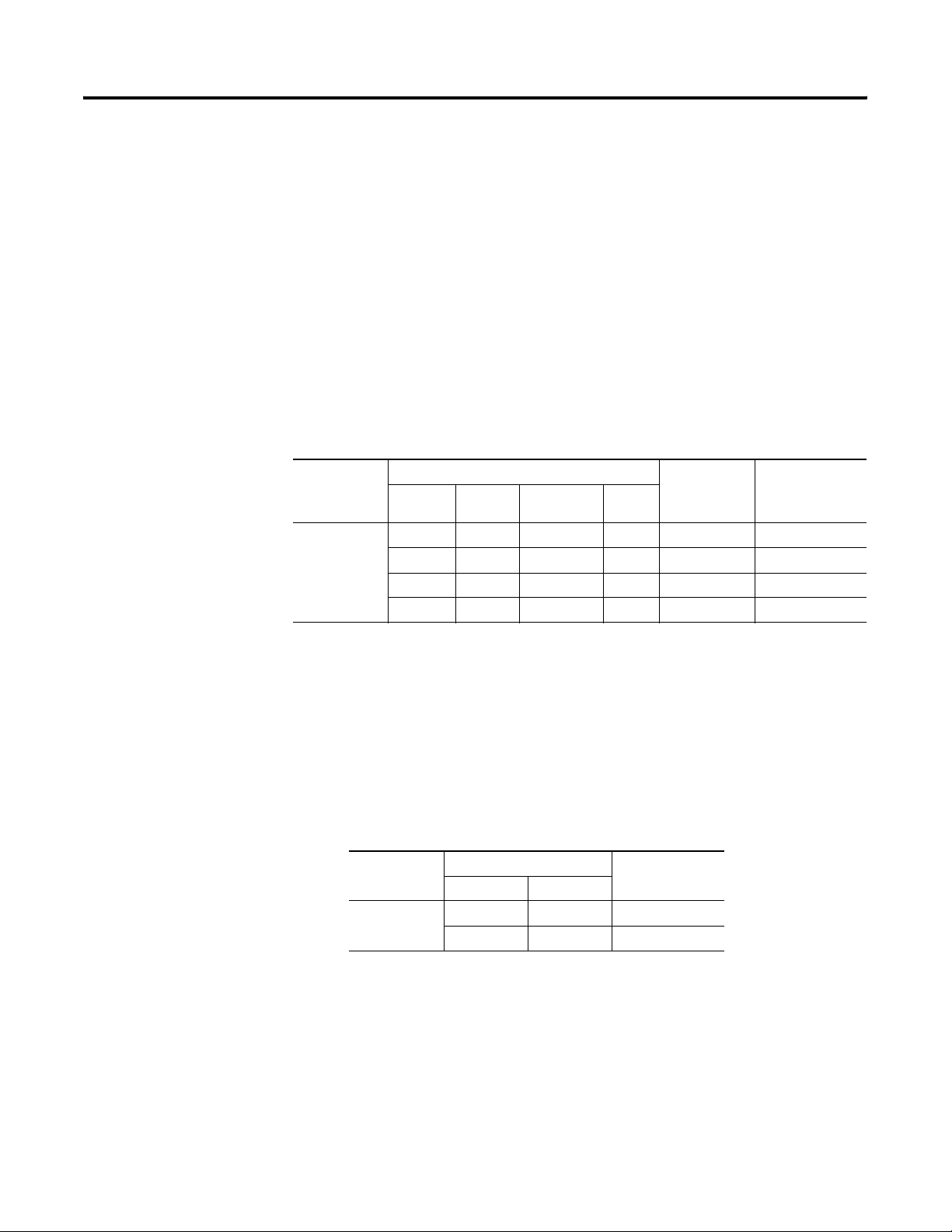
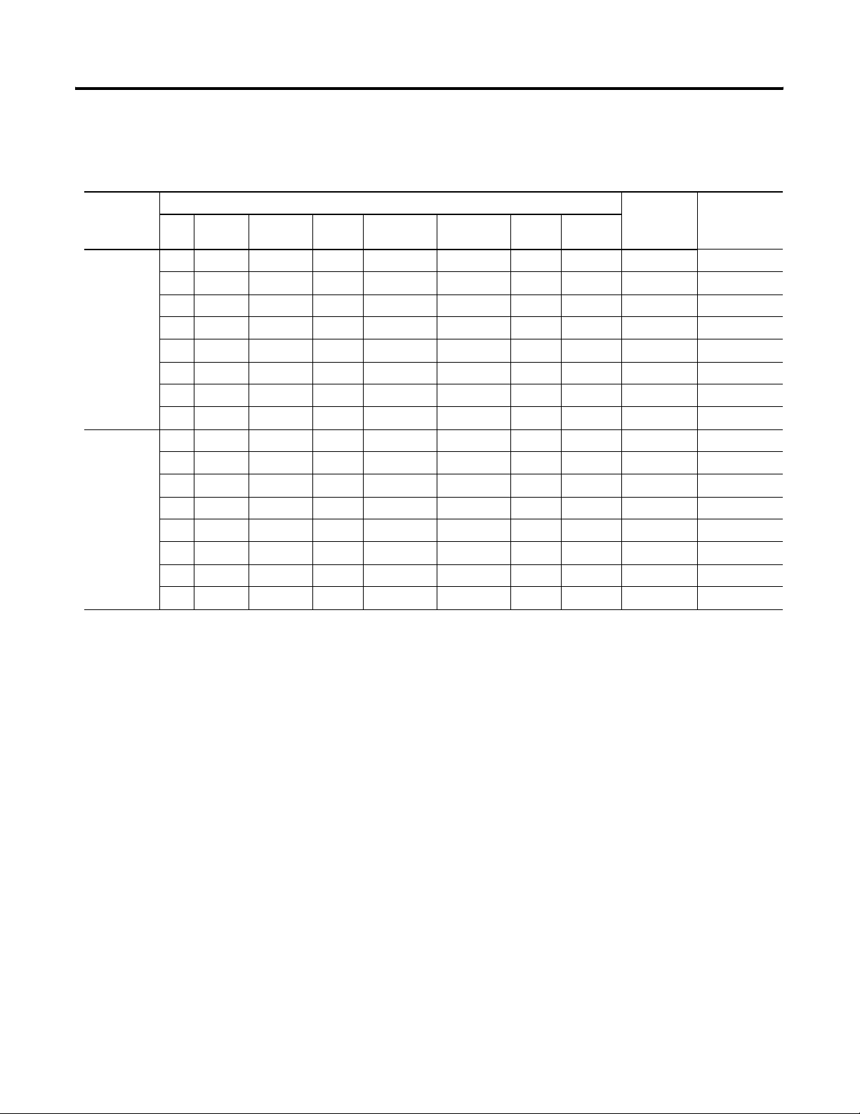
PanelView 300 Monochrome Terminals
The PanelView 300 terminal is only available with 24V dc input
power.
Operator
Input
Keypad x 2711-K3A2L1
Communication Port
DH-485 RS-232
(DH-485)
x 2711-K3A5L1
DeviceNet RS-232
(DF1)
x x 2711-K3A10L1
x 2711-K3A17L1
Printer Port
RS-232
Catalog
Number
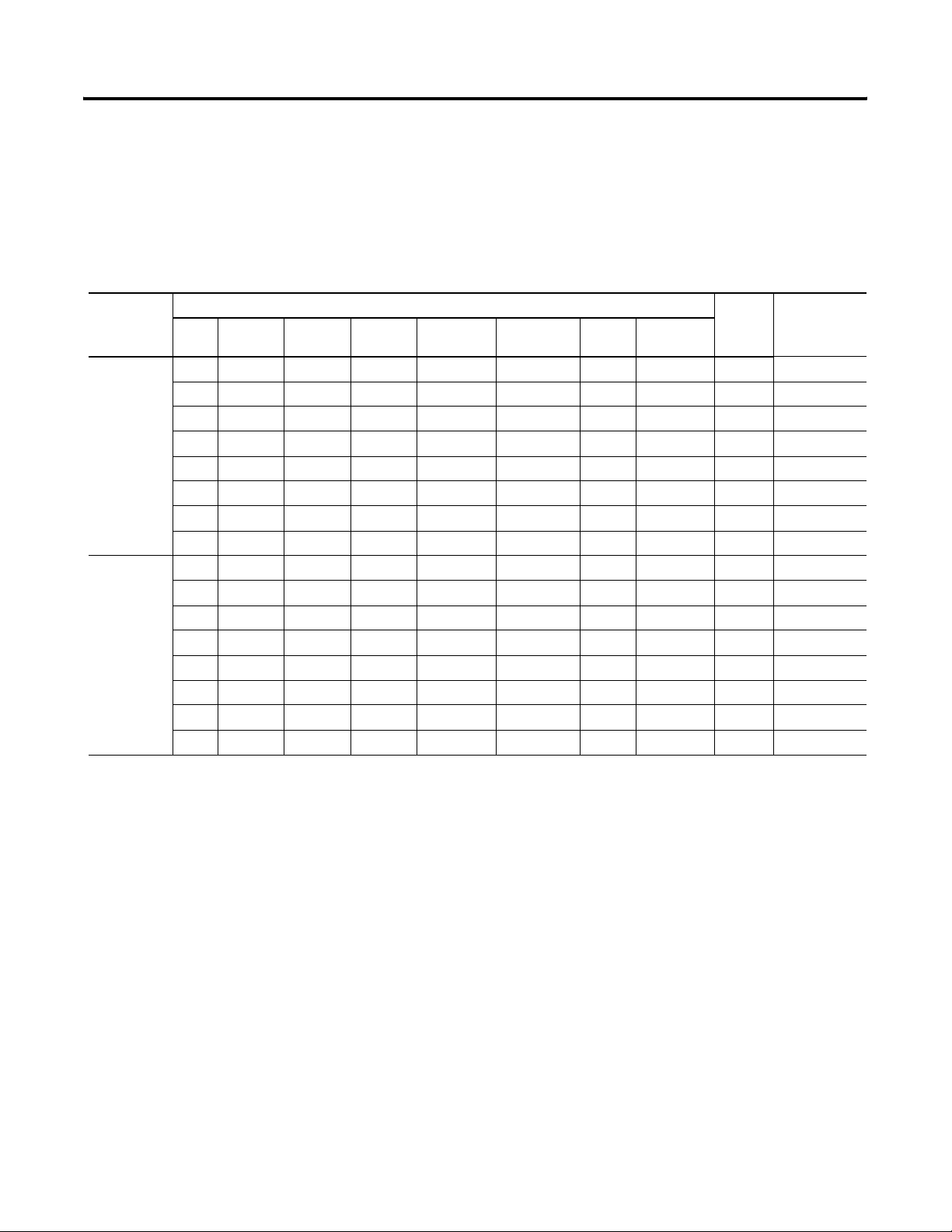
PanelView 300 Micro Monochrome Terminals
The PanelView 300 Micro is available only with 24V dc input power
and does not have a printer port. The PV300 Micro contains a single
RS-232 communication port which supports either DF1 or DH485
communication protocols as specified in the table below.
Operator
Input
Keypad x 2711-M3A19L1
Communication Port
DH-485 DF1
x 2711-M3A18L1
Catalog
Number
Publication 2711-UM014E-EN-P
Page 15

Terminal Overview 1-3
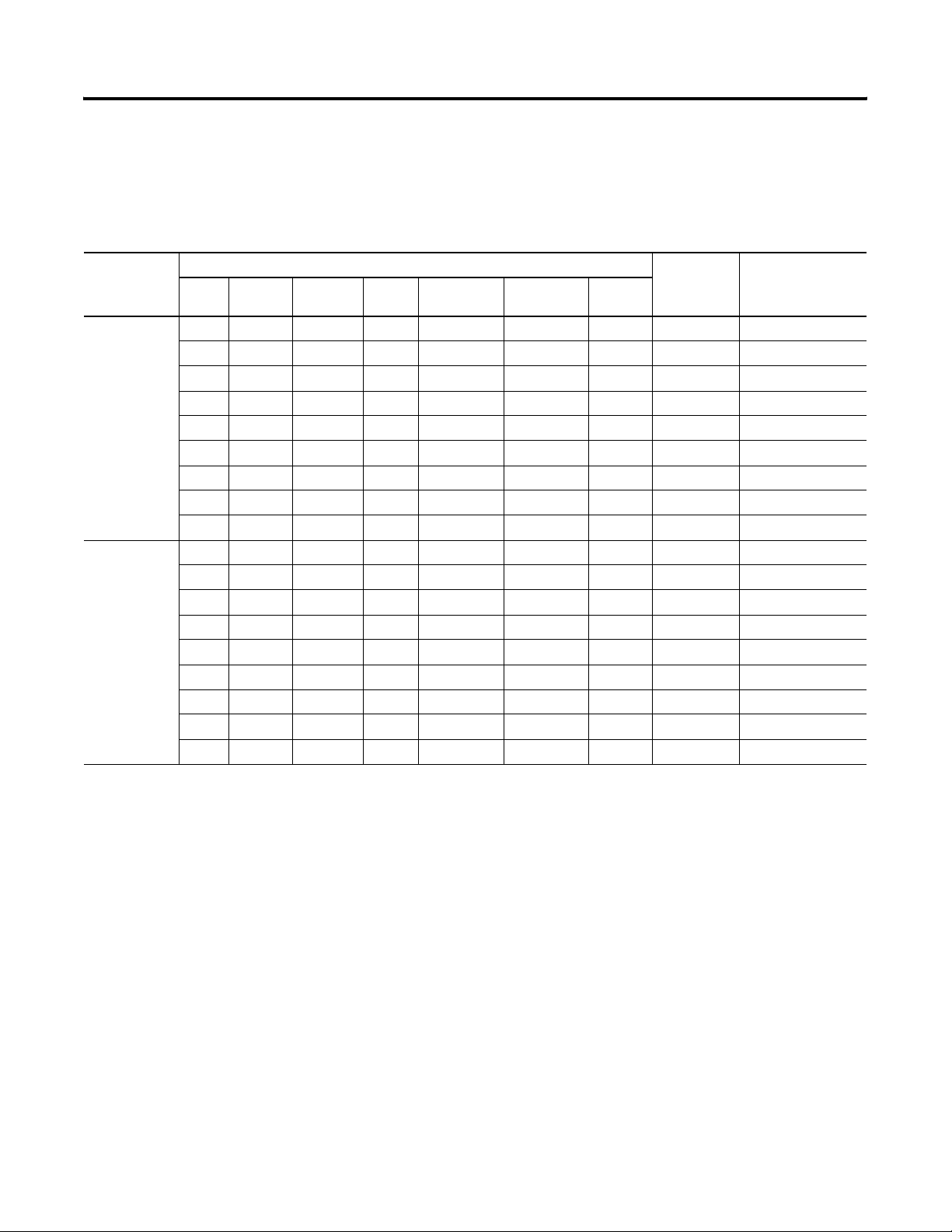
PanelView 550 Monochrome Terminals
The Touch Screen version of the PanelView 550 terminal is available
only with 24V dc power. The L1 in the catalog number indicates DC
power.
Operator
Input
Touch Screen
and Keypad
Keypad
Tou ch
Screen
(24V dc only)
(1)
Add L1 to the end of the catalog number for 24V dc power.
Add L2 to the end of a catalog number for stainless steel. Not available for the touch screen terminals.
Add L3 to the end of a catalog number for 24V dc power and stainless steel. Stainless steel is not available for the touch screen terminals.
Communication Port Printer
RIO DH-485 RS-232
(DH-485)
x x 2711-B5A1
x 2711-B5A2
x x 2711-B5A3
x 2711-B5A5
x x 2711-B5A9
x x 2711-K5A1
x 2711-K5A2
x x 2711-K5A3
x 2711-K5A5
x x 2711-K5A9
x x 2711-T5A1L1
x 2711-T5A2L1
x x 2711-T5A3L1
x 2711-T5A5L1
x x 2711-T5A9L1
DH+ DeviceNet ControlNet RS-232
(DF1)
x x 2711-B5A8
x x 2711-B5A10
x x 2711-B5A15
x x 2711-B5A16
x x 2711-K5A8
x x 2711-K5A10
x x 2711-K5A15
x x 2711-K5A16
x x 2711-T5A8L1
x x 2711-T5A10L1
x x 2711-T5A15L1
x x 2711-T5A16L1
Ethernet
x x 2711-B5A20
x x 2711-K5A20
x x 2711-T5A20L1
Port
RS-232
Catalog
Number
(1)
Publication 2711-UM014E-EN-P
Page 16

1-4 Terminal Overview
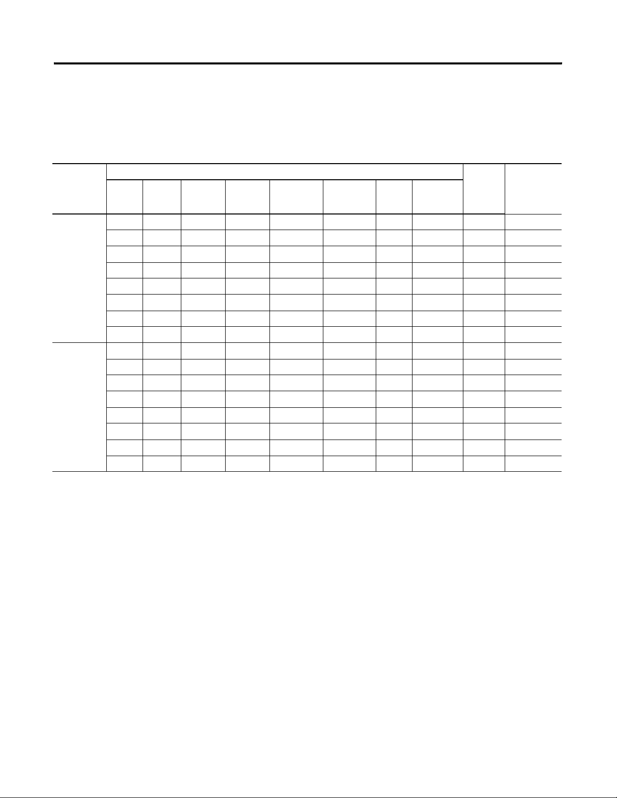
PanelView 600 Color Terminals
Operator
Input
Communication Port
RIO DH-485 RS-232
(DH-485)
x x 2711-B6C1
x 2711-B6C2
x x 2711-B6C3
x 2711-B6C5
Touch Screen
and Keypad
x x 2711-B6C9
x x 2711-K6C1
x 2711-K6C2
x x 2711-K6C3
x 2711-K6C5
Keypad
x x 2711-K6C9
x x 2711-T6C1L1
x 2711-T6C2L1
x x 2711-T6C3L1
x 2711-T6C5L1
Touch
Screen
(24V dc only)
(1)
Add L1 to the end of the catalog number for 24V dc power.
x x 2711-T6C9L1
DH+ DeviceNet ControlNet RS-232
(DF1)
Ethernet
Printer
Port
RS-232
Catalog
Number
(1)
x x 2711-B6C8
x x 2711-B6C10
x x 2711-B6C15
x x 2711-B6C16
x x 2711-B6C20
x x 2711-K6C8
x x 2711-K6C10
x x 2711-K6C15
x x 2711-K6C16
x x 2711-K6C20
x x 2711-T6C8L1
x x 2711-T6C10L1
x x 2711-T6C15L1
x x 2711-T6C16L1
x x 2711-T6C20L1
Publication 2711-UM014E-EN-P
Page 17
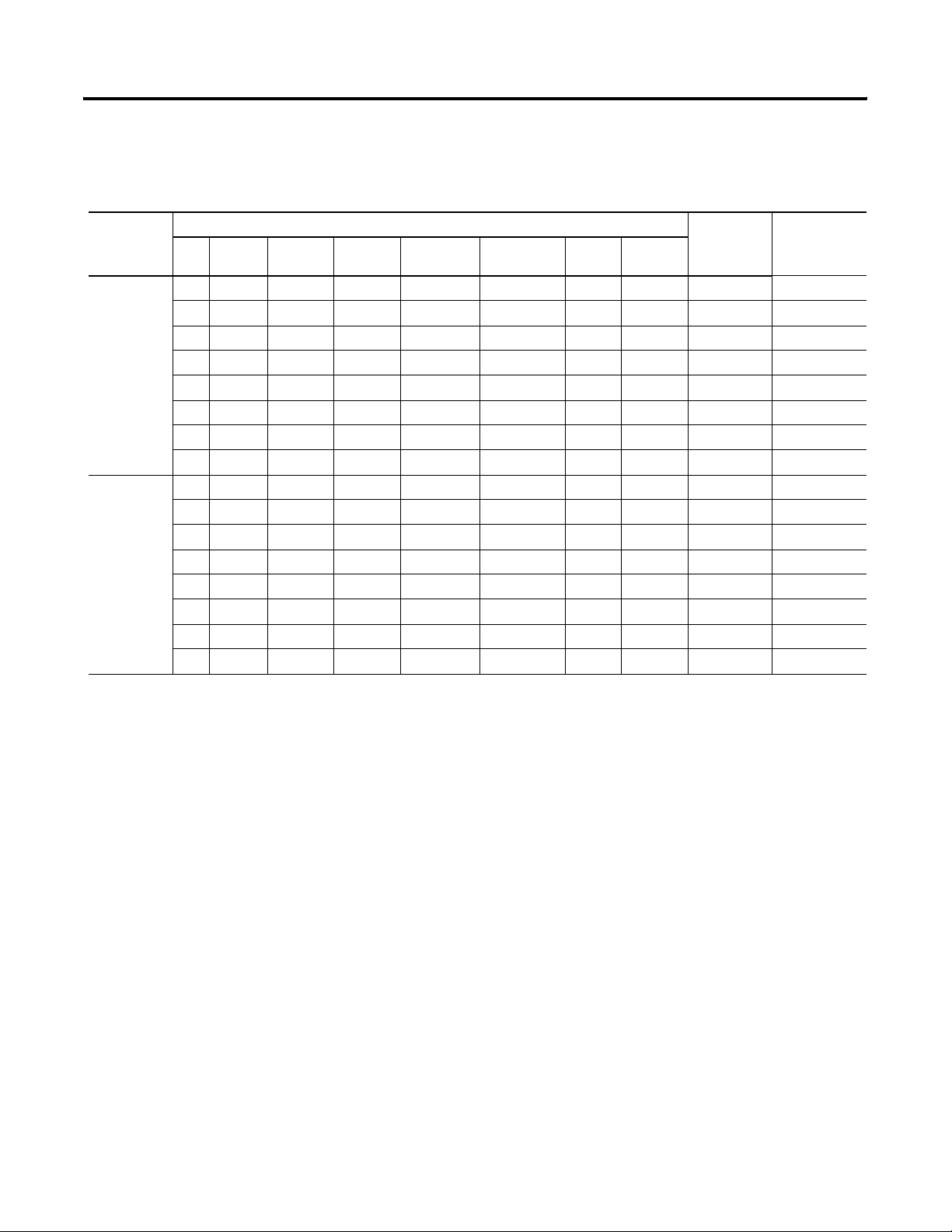
PanelView 900 Monochrome Terminals
These terminals are no longer available for purchase.
Terminal Overview 1-5
Operator
Input
Touch
Screen
Keypad
(1)
Add L1 to the end of the catalog number for 24V dc power.
Communication Port
RIO DH-485 RS-232
(DH-485)
x x 2711-T9A1
x 2711-T9A2
x x 2711-T9A3
x 2711-T9A5
x x 2711-T9A9
x x 2711-K9A1
x 2711-K9A2
x x 2711-K9A3
x 2711-K9A5
x x 2711-K9A9
DH+ DeviceNet ControlNet RS-232
(DF1)
x x 2711-T9A8
x x 2711-T9A10
x x 2711-T9A15
x x 2711-T9A16
x x 2711-K9A8
x x 2711-K9A10
x x 2711-K9A15
x x 2711-K9A16
Printer Port
RS-232
Catalog
Number
(1)
Publication 2711-UM014E-EN-P
Page 18
1-6 Terminal Overview
PanelView 900 Color Terminals
These terminals are no longer available for purchase.
Communication Port
Operator
Input
Tou ch
Screen
Keypad
(1)
Add L1 to the end of the catalog number for 24V dc power.
RIO DH-485 RS-232
(DH-485)
x x 2711-T9C1
x x 2711-T9C3
x x 2711-T9C9
x x 2711-K9C1
x x 2711-K9C3
x x 2711-K9C9
DH+ DeviceNet ControlNet RS-232
(DF1)
x x 2711-T9C8
x x 2711-T9C10
x x 2711-T9C15
x x 2711-T9C16
x x 2711-K9C8
x x 2711-K9C10
x x 2711-K9C15
x x 2711-K9C16
Ethernet
x x 2711-T9C20
x x 2711-K9C20
Printer
Port
RS-232
Catalog
Number
(1)
Publication 2711-UM014E-EN-P
Page 19
PanelView 1000 Color Terminals
Terminal Overview 1-7
Operator
Input
Communication Port
RIO DH-485 RS-232
(DH-485)
x x 2711-T10C1
x x 2711-T10C3
Tou ch
x x 2711-T10C9
Screen
x x 2711-K10C1
x x 2711-K10C3
x x 2711-K10C9
Keypad
(1)
Add L1 to the end of the catalog number for 24V dc power.
DH+ DeviceNet ControlNet RS-232
(DF1)
Ethernet
Printer Port
RS-232
Catalog
Number
(1)
x x 2711-T10C8
x x 2711-T10C10
x x 2711-T10C15
x x 2711-T10C16
x x 2711-T10C20
x x 2711-K10C8
x x 2711-K10C10
x x 2711-K10C15
x x 2711-K10C16
x x 2711-K10C20
Publication 2711-UM014E-EN-P
Page 20
1-8 Terminal Overview
PanelView 1000 Grayscale Terminals
Operator
Input
Communication Port
RIO DH-485 RS-232
(DH-485)
x x 2711-T10G1
x x 2711-T10G3
Tou ch
x x 2711-T10G9
Screen
x x 2711-K10G1
x x 2711-K10G3
x x 2711-K10G9
Keypad
(1)
Add L1 to the end of the catalog number for 24V dc power.
DH+ DeviceNet ControlNet RS-232
(DF1)
Ethernet
Printer Port
RS-232
Catalog
Number
(1)
x x 2711-T10G8
x x 2711-T10G10
x x 2711-T10G15
x x 2711-T10G16
x x 2711-T10G20
x x 2711-K10G8
x x 2711-K10G10
x x 2711-K10G15
x x 2711-K10G16
x x 2711-K10G20
Publication 2711-UM014E-EN-P
Page 21
Terminal Overview 1-9
PanelView 1400 Color Terminals
PanelView 1400 terminals will not be available after September 2005.
Contact your local Rockwell Automation sales office or authorized
distributor for suitable substitutes.
Operator
Input
Tou ch
Screen
Keypad
Communication Port
RIO DH-485 RS-232
(DH-485)
x x 2711-T14C1
x x 2711-T14C3
x x 2711-T14C9
x x x 2711-K14C1
x x 2711-K14C3
x x 2711-K14C9
DH+ DeviceNet ControlNet RS-232
(DF1)
x x 2711-T14C8
x x 2711-T14C10
x x 2711-T14C15
x x 2711-T14C16
x x 2711-K14C8
x x 2711-K14C10
x x 2711-K14C15
x x 2711-K14C16
Ethernet
x x 2711-K14C20
Printer
Port
RS-232
x 2711-T14C20
Catalog
Number
Publication 2711-UM014E-EN-P
Page 22
1-10 Terminal Overview
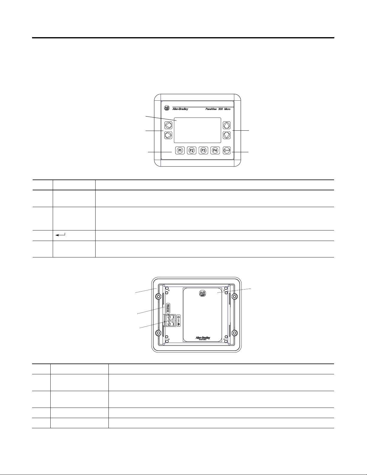
PanelView 300 Micro
This section defines features of the PanelView 300 Micro keypad
terminal.
Features
PanelView 300 Micro Features (Front)
4
2
13
# Feature Description
1 Function Keys
Use the function keys to initiate functions on the terminal display.
(F1 - F4)
2 Cursor Keys Use the cursor keys (left, right, up, down) as programmed function keys in addition to the F1 - F4 function
keys or to move the cursor in displayed lists, to select a numeric entry object, to enter configuration mode, or
to enter/modify numeric and ascii data.
2
3 Stores an entered value.
4 Keypad
Liquid crystal display with integral backlight. Displays application text, controls, graphics.
Terminal Display
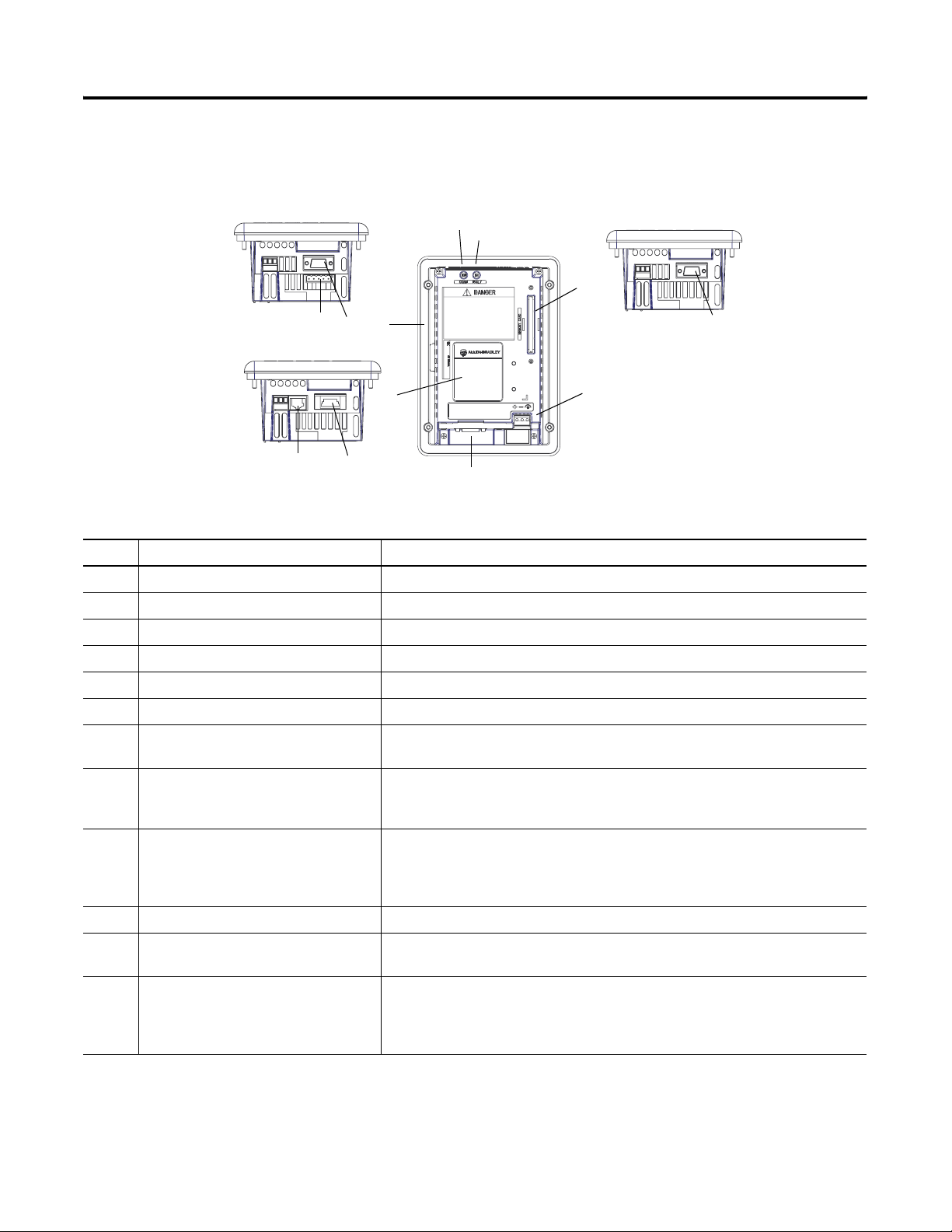
PanelView 300 Micro Features (Back)
3
2
1
# Feature Description
1 Power Connection
Te rm ina ls
2 DF1 or DH-485 (RS232)
Communication Port
3 Sealing Gasket Seals the front of the terminal to an enclosure or panel.
Connects to a 24V dc (11-30 V dc) external power source.
Connects to an SLC, PLC, or MicroLogix controller using an RS-232 connection. Also used for
downloading applications directly from a computer.
4
4 Nameplate Label Provides product information.
Publication 2711-UM014E-EN-P
Page 23
Terminal Overview 1-11
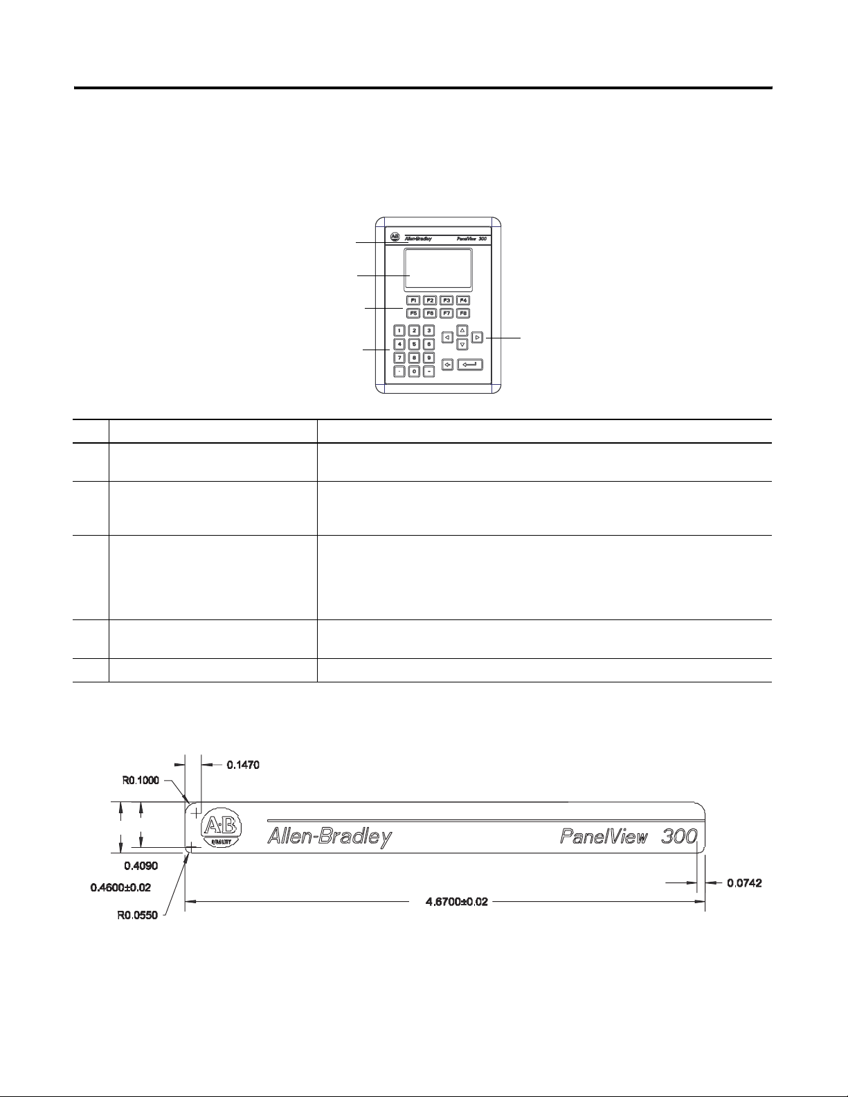
PanelView 300 Features
This section defines features of the PanelView 300 keypad terminal.
PanelView 300 Features (Front)
5
4
1
3
# Feature Description
1 Function Keys
(F1 - F8)
Use the function keys to initiate functions on the terminal display. These keys may have
custom legends.
2 Cursor Keys Use the up or down cursor keys to move the cursor up or down in a list or to
increment/decrement values. Use the left or right cursor keys to select an object with an
indicator bar, or to enter configuration mode.
3 Numeric Entry Keys 0-9 Enters numeric values.
. Enters a decimal point.
- Enters a negative value.
← Clears entered digits or cancels the scratchpad.
↵ Stores an entered value.
2
4 Keypad
Terminal Display
Initiate the function of a displayed object, such as an ON or OFF push button, by pressing
the corresponding function key (F1 - F8).
5 OEM Label Option (Series B and Later) Contact Rockwell Automation or your authorized distributor for custom label information
The following illustration shows the dimensions for the OEM label:
Publication 2711-UM014E-EN-P
Page 24
1-12 Terminal Overview
t
PanelView 300 Features (Back)
DeviceNet with additional RS-232 Port
3
4
RS-232 (DH-485 or DF1) without additional RS-232 Por
5
12
10
DH-485 without RS-232 Port
87
2
1
7, 8, 9, 10, 11, 12
6
9 or 11
# Feature Description
1 Nameplate Label Provides product information.
2 Sealing Gasket Seals the front of the terminal to an enclosure or panel.
3 COMM LED (Green) Indicates when communications is occurring.
4 FAULT LED (Red) Indicates firmware or hardware faults.
5 Memory Card Slot Accepts a memory card which stores applications.
6 Power Connection Terminals Connects to an external 24V dc power source (18-32V dc).
7 DH-485 Communication Port Connects to an SLC or MicroLogix controller, DH-485 network, or Wallmount Power
Supply (Cat. No. 1747-NP1).
8 DH-485
Programming Connector
Connects to a Personal Computer Interface Converter (Cat. No. 1747-PIC) for
transferring applications. Also connects to an SLC programmer, such as the
Hand-Held Terminal (Cat. No. 1747-PT1).
9 RS-232 (DH-485) Communication Port Connects to the Channel 0 port of an SLC 5/03, 5/04 or 5/05 controller for
point-to-point DH-485 communications. Connects to a MicroLogix controller through
an AIC+ Link Coupler. Also connects to the RS-232 serial port of a computer for
transferring applications.
10 DeviceNet Connector Connects to a DeviceNet network.
11 RS-232 (DF1)
Communication Port
12 RS-232 Printer/
Connects to a PLC, SLC or MicroLogix controller with a DF1 port. This port also
connects to the RS-232 port of a computer.
Connects to a printer (K3A10L1 version only).
File Transfer Port
On a DeviceNet terminal, this port also connects to the RS-232 port of a computer for
transferring applications.
Publication 2711-UM014E-EN-P
Page 25
Terminal Overview 1-13
PanelView 550 Features
Keypad Terminal
4
1
This section defines features of the PanelView 550 terminals.
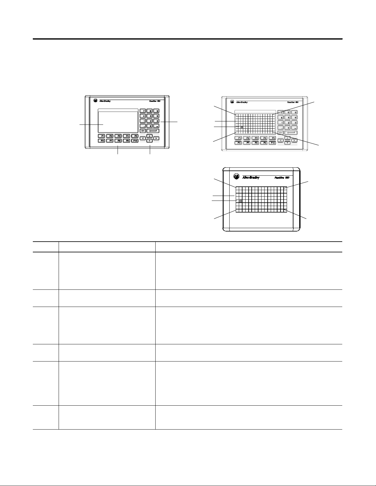
PanelView 550 Features (Front)
Keypad & Touch Screen Terminal
Cell 1
Cell 113
Cell 1
Cell 113
5
6
Touch Screen Terminal
5
6
Cell 128
3
2
Cell 16
Cell 128
Cell 16
# Feature Description
1 Function Keys (F1 - F10) On keypad terminals, use the function keys to initiate functions on the terminal
display. These keys may have custom legends.
On keypad & touch screen terminals, you can initiate functions using the function
keys and/or touch screen objects.
2 Cursor Keys Use the cursor keys to move the cursor in displayed lists, to select a numeric entry
object, or to enter configuration mode.
3 Numeric Entry Keys 0-9 Enters numeric values.
. Enters a decimal point.
- Enters a negative value.
← Clears entered digits or cancels the scratchpad.
↵ Stores an entered value.
4 Keypad Terminal Display On keypad terminals, initiate the function of a displayed object, such as an ON or
OFF push button, by pressing a function key (F1 - F10).
5 Touch Screen Terminal Display On touch screen or keypad & touch screen terminals, initiate the function of a
displayed object, such as an ON or OFF push button, by touching the screen object.
Each interactive screen object occupies one or more of 128 cells.
On keypad & touch screen terminals, you can initiate functions using the function
keys and/or touch screen objects.
6 Touch Cells (Touch Screen terminal) The 128 touch cells (16 columns x 8 rows) let you initiate functions by touching
the screen. Interactive screen objects are aligned with touch cells when the
application is created.
Publication 2711-UM014E-EN-P
Page 26
1-14 Terminal Overview
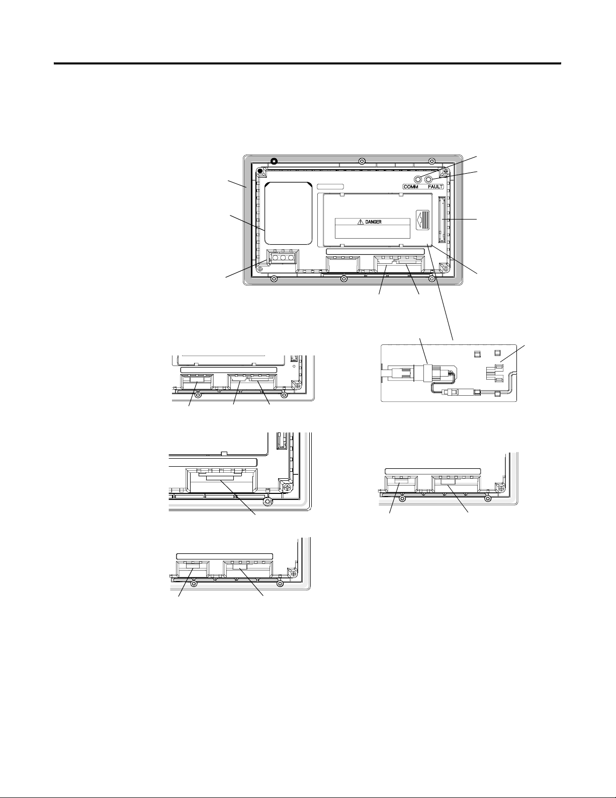
PanelView 550 Keypad or Keypad & Touch Screen Terminals (Back)
3
2
1
AC connector shown,
DC connector looks different
DH-485 with additional RS-232 Port
19 11
DH-485 without additional RS-232 Port
11
10
Backlight lamp behind access cover
(Series G and earlier)
4
5
6
7
10
8
9
RS-232 (DH-485)
without additional RS-232 Port
12
RS-232 (DH-485)
with additional RS-232 Port
19
12
Remote I/O, DF1, DH+, DeviceNet, ControlNet, Ethernet,
with additional RS-232 Port
13, 14, 15, 16, 17, or 18
19
Publication 2711-UM014E-EN-P
Page 27

# Feature Description
1 Power Connection Terminals Connects to external power source.
2 Nameplate Label Provides product information.
3 Sealing Gasket Seals the front of the terminal to an enclosure or panel.
4 COMM LED (Green) Indicates when communications is occurring.
5 FAULT LED (Red) Indicates firmware or hardware faults.
6 Memory Card Slot Accepts a memory card which stores applications.
7 Access Cover Provides access to the replaceable backlight lamp.
Terminal Overview 1-15
8 Backlight Lamp Light source for the display backlight. Light transmits through a fiber-optic bundle to
(1)
(1)
9 Spare Bulb Holder
the back of the LCD display.
Stores a spare backlight lamp.
10 DH-485 Communication Port Connects to an SLC or MicroLogix controller, DH-485 network, or Wallmount Power
Supply (Cat. No. 1747-NP1).
11 DH-485
Programming Connector
Connects to a Personal Computer Interface Converter (Cat. No. 1747-PIC) for
transferring applications. Also connects to an SLC programmer, such as the
Hand-Held Terminal (Cat. No. 1747-PT1).
12 RS-232 (DH-485) Communication Port Connects to the Channel 0 port of an SLC 5/03, 5/04, or 5/05 controller for
point-to-point DH-485 communications. Connects to a MicroLogix controller through
an AIC+ Link Coupler. Also connects to the RS-232 serial port of a computer for
transferring applications.
13 Remote I/O Port Connects to a scanner or sub-scanner on a Remote I/O network.
14 DH+ Communication Port Connects to a PLC-5, SLC 5/04, or ControlLogix controller on a DH+ link.
15 DeviceNet Connector Connects to a DeviceNet network.
16 ControlNet Connector Connects to a ControlLogix controller (with 1756-CNB module) or PLC-5 on a
ControlNet network.
17 RS-232 (DF1)
Connects to a PLC, SLC or MicroLogix controller with a DF1 port.
Communication Port
18 Ethernet Connector Connects to a PLC-5E or SLC 5/05 controller, or a ControlLogix, MicroLogix, FlexLogix
or CompactLogix (with appropriate bridge module) on an EtherNet/IP network.
19 RS-232 Printer/
Connects to a printer.
File Transfer Port
On Remote I/O, DH+, DF1, DeviceNet, EtherNet/IP, or ControlNet terminals, this port
also connects to the RS-232 port of a computer for transferring applications.
The RS-232 port on the DH-485 or RS-232 (DH-485) terminal is used to connect a
printer but not for file transfers.
(1)
Series H and later PanelView 550 Keypad and Keypad Touch Terminals have an integrated LED backlight. This backlight is non-replaceable.
Publication 2711-UM014E-EN-P
Page 28
1-16 Terminal Overview
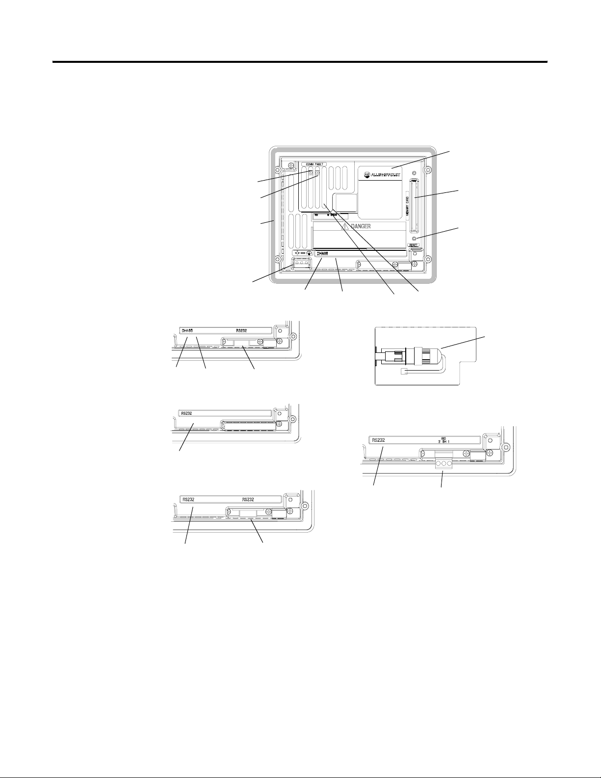
PanelView 550 Touch Screen Terminal Features (Back)
DH-485 without additional RS-232 Port
5
4
3
2
1
11
DH-485 with RS-232 Port
11
10
19
RS-232 (DH-485) without additional RS-232 Port
12
6
7
10
Backlight lamp behind access cover
(Series A only)
8
9
9
Remote I/O, DF1, DH+, DeviceNet, ControlNet, Ethernet,
with RS-232 Port
Publication 2711-UM014E-EN-P
RS-232 (DH-485) with additional RS-232 Port
12
19
19
13, 14, 15, 16, 17, or 18
Page 29

Terminal Overview 1-17
# Feature Description
1 Power Connection Terminals Connects to external DC power source.
2 Sealing Gasket Seals the front of the terminal to an enclosure or panel.
3 FAULT LED (Red) Indicates firmware or hardware faults.
4 COMM LED (Green) Indicates when communications is occurring.
5 Nameplate Label Provides product information.
6 Memory Card Slot Accepts a memory card which stores applications.
7 Reset Button Resets the terminal.
8 Access Cover
9 Backlight Lamp
Provides access to the replaceable backlight lamp.
Light source for the display backlight.
(1)
(1)
10 DH-485 Communication Port Connects to an SLC or MicroLogix controller, DH-485 network, or Wallmount Power
Supply (Cat. No. 1747-NP1).
11 DH-485
Programming Connector
Connects to a Personal Computer Interface Converter (Cat. No. 1747-PIC) for
transferring applications. Also connects to an SLC programmer, such as the
Hand-Held Terminal (Cat. No. 1747-PT1).
12 RS-232 (DH-485) Communication Port Connects to the Channel 0 port of an SLC 5/03, 5/04, or 5/05 for point-to-point
DH-485 communications. Connects to a MicroLogix controller through an AIC+ Link
Coupler. Also connects to the RS-232 serial port of a computer for transferring
applications.
13 Remote I/O Port Connects to a scanner or sub-scanner on a Remote I/O network.
14 DH+ Communication Port Connects to a PLC-5, SLC 5/04, or ControlLogix controller on a DH+ link.
15 DeviceNet Connector Connects to a DeviceNet network.
16 ControlNet Connector Connects to a ControlLogix controller (with 1756-CNB module) or PLC-5 on a
ControlNet network.
17 RS-232 (DF1)
Connects to a PLC, SLC or MicroLogix controller with a DF1 port.
Communication Port
18 Ethernet Connector Connects to a PLC-5E or SLC 5/05 controller, or a ControlLogix, MicroLogix, FlexLogix
or CompactLogix (with appropriate bridge module) on an EtherNet/IP network.
19 RS-232 Printer/
Connects to a printer.
File Transfer Port
On Remote I/O, DH+, DF1, DeviceNet, EtherNet/IP, or ControlNet terminals, this port
also connects to the RS-232 port of a computer for transferring applications.
The RS-232 port on the DH-485 or RS-232 (DH-485) terminal is used to connect a
printer but not for file transfers.
(1)
Series B and later PanelView 550 Touch Terminals have an integrated LED backlight. This backlight is non-replaceable.
Publication 2711-UM014E-EN-P
Page 30
1-18 Terminal Overview
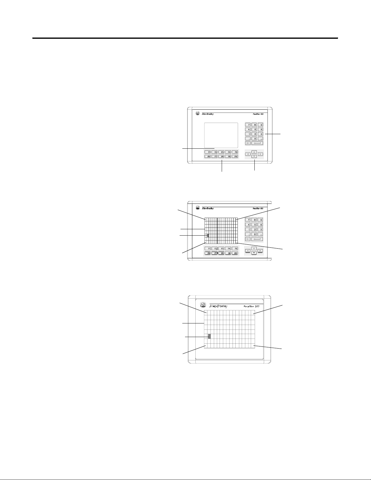
PanelView 600 Features
This section defines features of the PanelView 600 terminals.
PanelView 600 Features (Front)
Keypad Terminal
3
4
1
Keypad & Touch Screen Terminal
Cell 1
5
6
2
Cell 16
Cell 113
Cell 1
Cell 113
Cell 128
Touch Screen Terminal
Cell 16
5
6
Cell 128
Publication 2711-UM014E-EN-P
Page 31

Terminal Overview 1-19
# Feature Description
1 Function Keys (F1 - F10) Use the function keys on keypad terminals to initiate functions on the terminal
display. These keys may have custom legends.
On the keypad & touch screen terminals, you can initiate functions using the
function keys and/or touch screen objects.
2 Cursor Keys Use the cursor keys to move the cursor in displayed lists, to select a numeric entry
object, or to enter configuration mode.
3 Numeric Entry Keys 0-9 Enters numeric values.
. Enters a decimal point.
- Enters a negative value.
← Clears entered digits or cancels the scratchpad.
↵ Stores an entered value.
4 Keypad Terminal Display On keypad terminals, initiate the function of a displayed object, such as an ON or
OFF push button, by pressing a function key (F1 - F10).
5 Touch Screen
Terminal Display
6 Touch Cells
(Touch Screen terminal)
On keypad & touch screen terminals, initiate the function of a displayed object,
such as an ON or OFF push button, by touching the screen object. Each interactive
screen object occupies one or more of 128 cells.
On touch screen & keypad terminals, you can initiate functions, using the function
keys and/or touch screen objects.
The 128 touch cells (16 columns x 8 rows) let you initiate functions by touching
the screen. Interactive screen objects are aligned with touch cells when the
application is created.
Publication 2711-UM014E-EN-P
Page 32

1-20 Terminal Overview
PanelView 600 Keypad or Keypad & Touch Screen Terminal (Back)
Remote I/O, DF1, DH+, DeviceNet, ControlNet,
or Ethernet with additional RS-232 Port
4
10, 11, 12, 13, 14, or 15
16
DH-485 without additional RS-232 Port
7
8
DH-485 with additional RS-232 Port
16
87
RS-232 (DH-485)
without additional RS-232 Port
3
2
1
7, 8, 9, 10
11, 12, 13, 14, 15, 16
RS-232 (DH-485) with additional RS-232 Port
5
6
Publication 2711-UM014E-EN-P
9
16
9
Page 33

Terminal Overview 1-21
# Feature Description
1 Power Connection Terminals Connects to external power source.
2 Nameplate Label Provides product information.
3 Memory Card Slot Accepts a memory card which stores applications.
4 Sealing Gasket Seals the front of the terminal to an enclosure or panel.
5 FAULT LED (Red) Indicates firmware or hardware faults.
6 COMM LED (Green) Indicates when communications is occurring.
7 DH-485 Communication Port Connects to an SLC or MicroLogix controller, DH-485 network, or Wallmount Power
Supply (Cat. No. 1747-NP1).
8 DH-485
Programming Connector
Connects to a Personal Computer Interface Converter (Cat. No. 1747-PIC) for
transferring applications. Also connects to an SLC programmer, such as the
Hand-Held Terminal (Cat. No. 1747-PT1).
9 RS-232 (DH-485) Communication Port Connects to the Channel 0 port of an SLC 5/03, 5/04, or 5/05 for point-to-point
DH-485 communications. Connects to a MicroLogix controller through an AIC+ Link
Coupler. Also connects to the RS-232 serial port of a computer for transferring
applications.
10 Remote I/O Port Connects to a scanner or sub-scanner on a Remote I/O network.
11 DH+ Communication Port Connects to a PLC-5, SLC 5/04, or ControlLogix controller on a DH+ link.
12 DeviceNet Connector Connects to a DeviceNet network.
13 ControlNet Connector Connects to a ControlLogix controller (with 1756-CNB module) or PLC-5 on a
ControlNet network.
14 (RS-232) DF1
Connects to a PLC, SLC or MicroLogix controller with a DF1 port.
Communication Port
15 Ethernet Connector Connects to a PLC-5E or SLC 5/05 controller, or a ControlLogix, MicroLogix, FlexLogix
or CompactLogix (with appropriate bridge module) on an EtherNet/IP network.
16 RS-232 Printer/
Connects to a printer.
File Transfer Port
On Remote I/O, DH+, DF1, DeviceNet, EtherNet/IP, or ControlNet terminals, this port
also connects to the RS-232 port of a computer for transferring applications.
The RS-232 port on the DH-485 or RS-232 (DH-485) terminal is used to connect a
printer but not for file transfers.
Publication 2711-UM014E-EN-P
Page 34

1-22 Terminal Overview
PanelView 600 Touch-Screen Terminal Features (Back)
Remote I/O, DF1, DH+, DeviceNet, ControlNet,
or Ethernet with additional RS-232 Port
5
11, 12, 13, 14, 15, or 16
17
DH-485 without additional RS-232 Port
8
9
DH-485 with additonal RS-232 Port
17
8
9
RS-232 (DH-485)
without additional RS-232 Port
4
3
2
1
8, 9, 10, 11
12, 13, 14, 15, 16, 17
RS-232 (DH-485) with additional RS-232 Port
6
7
Publication 2711-UM014E-EN-P
10
17
10
Page 35

Terminal Overview 1-23
# Feature Description
1 Power Connection Terminals Connects to external power source.
2 Nameplate Label Provides product information.
3 Fault LED (Red) Indicates firmware or hardware faults.
4 COMM LED (Green) Indicates when communications is occurring.
5 Sealing Gasket Seals the front of the terminal to an enclosure or panel.
6 Reset Button Resets the terminal.
7 Memory Card Slot Accepts a memory card which stores applications.
8 DH-485 Communications Port Connects to an SLC or MicroLogix controller, DH-485 network, or Wallmount Power
Supply (Cat. No. 1747-NP1).
9 DH-485
Programming Connector
Connects to a Personal Computer Interface Converter (Cat. No. 1747-PIC) for
transferring applications. Also connects to an SLC programmer, such as the
Hand-Held Terminal (Cat. No. 1747-PT1).
10 RS-232 (DH-485)
Communication Port
Connects to the Channel 0 port of an SLC 5/03, 5/04, or 5/05 for point-to-point
DH-485 communications. Connects to a MicroLogix controller through an AIC+ Link
Coupler. Also connects to the RS-232 serial port of a computer for transferring
applications.
11 Remote I/O Port Connects to a scanner or sub-scanner on a Remote I/O network.
12 DH+ Communication Port Connects to a PLC-5, SLC 5/04, or ControlLogix controller on a DH+ link.
13 DeviceNet Connector Connects to a DeviceNet network.
14 ControlNet Connector Connects to a ControlLogix controller (with 1756-CNB module) or PLC-5 on a
ControlNet network.
15 RS-232 (DF1)
Connects to a PLC, SLC or MicroLogix controller with a DF1 port.
Communication Port
16 Ethernet Connector Connects to a PLC-5E or SLC 5/05 controller, or a ControlLogix, MicroLogix, FlexLogix
or CompactLogix (with appropriate bridge module) on an EtherNet/IP network.
17 RS-232 Printer/
Connects to a printer.
File Transfer Port
On Remote I/O, DH+, DF1, DeviceNet, EtherNet/IP, or ControlNet terminals, this port
also connects to the RS-232 port of a computer for transferring applications.
The RS-232 port on the DH-485 or RS-232 (DH-485) terminal is used to connect a
printer but not for file transfers.
Publication 2711-UM014E-EN-P
Page 36

1-24 Terminal Overview
PanelView 900
Features
4
1
(1)
/1000
Keypad Terminal
2
This section defines features of the PanelView 900 and 1000 terminals.
PanelView 900/1000 Terminal Features (Front)
Touch Screen Terminal
Cell 1
5
6
3
Cell 361
Cell 24
Cell 384
(1)
PanelView 900 terminals are no longer available. Conatct your local sales office or authorized Rockwell Distributor for suitable substitutes.
Publication 2711-UM014E-EN-P
Page 37

Terminal Overview 1-25
# Feature Description
1 Function Keys (F1 - F16) Use the function keys on keypad terminals to initiate functions on the terminal
display. These keys may have custom legends.
2 Cursor Keys Use the cursor keys to move the cursor in displayed lists, to select a numeric entry
object or to enter configuration mode.
3 Numeric Entry Keys 0-9 Enters numeric values.
. Enters a decimal point.
- Enters a negative value.
← Clears entered digits or cancels the scratchpad.
↵ Stores an entered value.
4 Keypad Terminal Display On keypad terminals, initiate the function of a displayed object, such as an ON or
OFF push button, by pressing a function key (F1 - F16).
5 Touch Screen
Terminal Display
6 Touch Cells
(Touch Screen terminal)
On touch screen terminals, initiate the function of a displayed object, such as an
ON or OFF push button, by touching the screen object. Each interactive screen
object occupies one or more of 384 cells.
The 384 touch cells (24 columns x 16 rows) let you initiate functions by touching
the screen. Interactive screen objects are aligned with touch cells when the
application is created.
Publication 2711-UM014E-EN-P
Page 38

1-26 Terminal Overview
PanelView 900/1000 Terminal Features (Back)
Remote I/O, DF1, DH+, DeviceNet, Ethernet,
or ControlNet with additional RS-232 Port
1711, 12, 13, 14, 15, or 16
4
Back View
Touch Screen Terminal
3
DH-485 Version without additional RS-232 Port
98
DH-485 with additional RS-232 Port
17
9
8
RS-232 (DH-485) without additional RS-232 Port
10
2
1
8, 9, 10
11, 12, 13, 14, 15, 16, 17
4
3
2
5
6
7
Back View
Keypad Terminal
5
6
RS-232 (DH-485) with additional RS-232 Port
Publication 2711-UM014E-EN-P
1
8, 9, 10
11, 12, 13, 14, 15, 16, 17
17
10
7
Page 39

Terminal Overview 1-27
# Feature Description
1 Power Connection Terminals Connects to external power source.
2 Nameplate Label Provides product information.
3 Reset Button Resets the terminal.
4 Sealing Gasket Seals the front of the terminal to an enclosure or panel.
5 Memory Card Slot Accepts a memory card which stores applications.
6 FAULT LED (Red) Indicates firmware or hardware faults.
7 COMM LED (Green) Indicates when communications is occurring.
8 DH-485 Communication Port Connects to an SLC or MicroLogix controller, DH-485 network, or Wallmount Power
Supply (Cat. No. 1747-NP1).
9 DH-485
Programming Connector
Connects to a Personal Computer Interface Converter (Cat. No. 1747-PIC) for
transferring applications. Also connects to an SLC programmer, such as the
Hand-Held Terminal (Cat. No. 1747-PT1).
10 RS-232 (DH-485) Communication Port Connects to the Channel 0 port of an SLC 5/03, 5/04, or 5/05 for point-to-point
DH-485 communications. Connects to a MicroLogix controller through an AIC+ Link
Coupler. Also connects to the RS-232 serial port of a computer for transferring
applications.
11 Remote I/O Port Connects to a scanner or sub-scanner on a Remote I/O network.
12 DH+ Communication Port Connects to a PLC-5, SLC 5/04, or ControlLogix controller on a DH+ link.
13 DeviceNet Connector Connects to a DeviceNet network.
14 ControlNet Connector Connects to a ControlLogix controller (with 1756-CNB module) or PLC-5 on a
ControlNet network.
15 RS-232 (DF1)
Connects to a PLC, SLC or MicroLogix controller with a DF1 port.
Communication Port
16 Ethernet Connector Connects to a PLC-5E or SLC 5/05 controller, or a ControlLogix, MicroLogix, FlexLogix
or CompactLogix (with appropriate bridge module) on an EtherNet/IP network.
17 RS-232 Printer/
Connects to a printer.
File Transfer Port
On Remote I/O, DH+, DF1, DeviceNet, EtherNet/IP, or ControlNet terminals, this port
also connects to the RS-232 port of a computer for transferring applications.
The RS-232 port on the DH-485 or RS-232 (DH-485) terminal is used to connect a
printer but not for file transfers.
Publication 2711-UM014E-EN-P
Page 40

1-28 Terminal Overview
PanelView 1400 Features
Keypad Terminal
4
1
This section defines features of the PanelView 1400 terminals.
PanelView 1400 terminals will not be available after September 2005.
Contact your local Rockwell Automation sales office or authorized
distributor for suitable substitutes.
PanelView 1400 Terminal Features (Front)
Touch Screen Terminal
Cell 1
5
3
6
Cell 361
2
Cell 24
Cell 384
Publication 2711-UM014E-EN-P
Page 41

Terminal Overview 1-29
# Feature Description
1 Function Keys (F1 - F21) Use the function keys on keypad terminals to initiate functions on the terminal
display. These keys may have custom legends.
2 Cursor Keys Use the cursor keys to move the cursor in displayed lists, to select a numeric entry
object, or to enter configuration mode.
3 Numeric Entry Keys 0-9 Enters numeric values.
. Enters a decimal point.
- Enters a negative value.
← Clears entered digits or cancels the scratchpad.
↵ Stores an entered value.
4 Keypad Terminal Display On keypad terminals, initiate the function of a displayed object, such as an ON or
OFF push button, by pressing a function key (F1 - F21).
5 Touch Screen
Terminal Display
6 Touch Cells
(Touch Screen terminal)
On touch screen terminals, initiate the function of a displayed object, such as an
ON or OFF push button, by touching the screen object. Each interactive screen
object occupies one or more of 384 cells.
The 384 touch cells (24 columns x 16 rows) let you initiate functions by touching
the screen. Interactive screen objects are aligned with touch cells when the
application is created.
Publication 2711-UM014E-EN-P
Page 42

1-30 Terminal Overview
PanelView 1400 Terminal Features (Back and Sides)
Remote I/O, DF1, DH+, DeviceNet, ControlNet,
or Ethernet with additional RS-232 Port
16
7, 8, 9
10, 11, 12
13, 14, 15, 16
10, 11, 12, 13, 14, or 15
DH-485 with additional RS-232 Port
7
8
16
19
18
17
6
5
4
3
1
2
Left Side
20
RS-232 (DH-485) with additional RS-232 Port
9
16
Right Side
21
Publication 2711-UM014E-EN-P
Page 43

Terminal Overview 1-31
# Feature Description
1 Brightness Control Adjusts the brightness of the color display.
2 Contrast Control Adjusts the contrast of the color display.
3 Nameplate Label Provides product information.
4 FAULT LED (Red) Indicates firmware or hardware faults.
5 COMM LED (Green) Indicates when communications is occurring.
6 Power Connection Terminals Connects to external power source.
7 DH-485 Communication Port Connects to an SLC or MicroLogix controller, DH-485 network, or Wallmount Power
Supply (Cat. No. 1747-NP1).
8 DH-485
Programming Connector
9 RS-232 (DH-485) Communication Port Connects to the Channel 0 port of an SLC 5/03, 5/04, or 5/05 for point-to-point
10 Remote I/O Port Connects to a scanner or sub-scanner on a Remote I/O network.
11 DH+ Communication Port Connects to a PLC-5, SLC 5/04, or ControlLogix controller on a DH+ link.
12 DeviceNet Connector Connects to a DeviceNet network.
13 ControlNet Connector Connects to a ControlLogix controller (with 1756-CNB module) or PLC-5 on a
14 RS-232 (DF1)
Communication Port
15 Ethernet Connector Connects to a PLC-5E or SLC 5/05 controller, or a ControlLogix, MicroLogix, FlexLogix
16 RS-232 Printer/
File Transfer Port
Connects to a Personal Computer Interface Converter (Cat. No. 1747-PIC) for
transferring applications. Also connects to an SLC programmer, such as the
Hand-Held Terminal (Cat. No. 1747-PT1).
DH-485 communications. Connects to a MicroLogix controller through an AIC+ Link
Coupler. Also connects to the RS-232 serial port of a computer for transferring
applications.
ControlNet network.
Connects to a PLC, SLC or MicroLogix controller with a DF1 port.
or CompactLogix (with appropriate bridge module) on an EtherNet/IP network.
Connects to a printer. On Remote I/O, DH+, DF1, DeviceNet, EtherNet/IP, or
ControlNet terminals, this port also connects to the RS-232 port of a computer for
transferring applications.
The RS-232 port on the DH-485 or RS-232 (DH-485) terminal is used to connect a
printer but not for file transfers.
17 Memory Card Eject Button Ejects memory card from slot.
18 Memory Card Slot Accepts a memory card which stores applications.
19 Sealing Gasket Seals the front of the terminal to an enclosure or panel.
20 Reset Button Resets the terminal.
21 CRT Board Adjustments See the warning below.
ATTENTION
Only qualified service technicians should access the
CRT board adjustments. Failure to follow this
caution could result in electrical shock, a misadjusted
monitor, or a damaged monitor.
Publication 2711-UM014E-EN-P
Page 44

1-32 Terminal Overview
Applications
PanelView terminals operate with custom designed applications. The
first time you power on the terminal, (no application file loaded), the
terminal displays the Configuration Mode menu. Chapter 3 describes
the terminal functions you can configure from this menu.
TIP
Remote I/O terminals provide an out-of-box
application for setting Remote I/O communication
parameters.
If an application is loaded, the terminal displays the application’s
start-up screen.
TIP
How the terminal operates depends on the application and the type of
terminal (touch screen or keypad).
The application designer is responsible for
documenting the operation of the application and
selecting a startup screen.
Publication 2711-UM014E-EN-P
Page 45

Terminal Overview 1-33
Touch Screen Operation
Applications for touch screen terminals are controlled by touching
screen objects.
Keypad Operation
Applications for keypad terminals are controlled by pressing function
keys that correspond to screen objects. Data is entered manually using
the numeric entry keys.
A function key legend kit is available for each terminal (except the
300 Micro) to create custom labels for the function keys. See the
accessories at the end of this chapter.
ATTENTION
Do not press multiple touch screen objects or
multiple function keys at the same time. This may
result in unintended operation.
Publication 2711-UM014E-EN-P
Page 46

1-34 Terminal Overview
Configuration Mode Menu
Terminal Messages
You can configure terminal functions from the Configuration Mode
menu including:
• select a language
• upload/download applications with a memory card
• set or display serial communication parameters
• select preset values
• obtain terminal and application information
• adjust screen parameters
• set time and date
• set printer parameters (for terminals with an RS-232 printer port)
• return to run mode
Chapter 3 describes how to enter configuration mode and operations
you can perform using the Configuration Mode menu.
Terminal messages display:
• status of an operation
• minor faults, errors, or numeric entry mistakes
• operator prompts
Printing
Appendix B describes terminal messages and provides a list of
recommended actions.
PanelView terminals equipped with an RS-232 printer port can print:
• triggered messages in a message display
• triggered states of a multistate indicator
• alarm messages
• alarm list
Print attributes for objects are defined in the application.
Any printer that supports the IBM enhanced character set can be
connected to the RS-232 printer port of a PanelView terminal.
Publication 2711-UM014E-EN-P
Page 47

Terminal Overview 1-35
Alarm List
PanelView terminals support an Alarm List queue to store information
on triggered alarms. The Alarm List stores a maximum of 100 alarms
or as many as the terminal can hold in nonvolatile RAM. The number
of alarms stored in the list is configured using the PanelBuilder32
software.
The Alarm List stores the following data for each alarm:
• acknowledge indicator
• alarm date and time
• acknowledge date and time
• alarm trigger value
• alarm text including variables
The Alarm List is cleared:
• when an application is downloaded to the terminal
• when the terminal is reset or power is cycled
The Alarm List object may appear on the Alarm Banner or other
application screens. The data that displays in the Alarm List is
configured using the PanelBuilder32 Software.
Accessories
Catalog No. 300M 300 550 600 900 1000 1400 Description
2711-ND3 x xxxxx x Windows software required for creating
Software
PanelView applications on a personal computer.
Function Key Legend Kits
Catalog No. 300 550 600 900 1000 1400 Description
2711-NF1 x 5 legend inserts with key labels F1-F10 on one side. Use blank side to create
2711-NF2A x 1 legend insert for PV900 keypad (monochrome) terminal with key labels
2711-NF2C x 1 legend insert for PV900 keypad (color) terminal with key labels F1-F16 on
2711-NF4 x 1 legend insert with key labels F1-F10 on one side. Use blank side to create
2711-NF5 x 2 legend inserts. One has key labels F1-F16; the other has key labels F17-F21.
2711-NF6 x 1 legend insert with key labels F1-F16. Use blank side to create custom labels.
2711-NF7 x 2 legend inserts with key labels F1-F4 and F5-F8. Use blank side to create
custom labels.
F1-F16 on one side. Use blank side to create custom labels.
one side. Use blank side to create custom labels.
custom labels.
Use blank sides to create custom labels.
custom labels.
Publication 2711-UM014E-EN-P
Page 48

1-36 Terminal Overview
Memory Cards and Retainer
Catalog No. 300 550 600 900 1000 1400 Description
2711-NM11
2711-NM13 xxxxx x 2M flash memory card for storing applications.
2711-NM14 xxxxx x 4M flash memory card for storing applications.
2711-NM15 xxxxx x 10M flash memory card for storing applications.
2711-NM216
2711-NM232 xxxxx x 32M flash ATA card for storing applications and font files.
2711-NMCC xxxx Secures memory card in the PanelView 500/600 keypad or the PanelView
2711-NMCD x Secures memory card in 550 touch screen terminal and prevents electrostatic
2711-NMCE x x Secures memory card in PanelView 300 keypad and 600 touch screen
(1)
(1)
Contact Rockwell Automation for availability.
xxxxx x 256K memory card for storing applications.
(1)
xxxxx x 16M flash ATA card for storing applications and font files.
900/1000 keypad and touch screen. Prevents electrostatic discharge.
discharge.
terminals and prevents electrostatic discharge.
Antiglare Overlay
Self-adhesive filters minimize the reflection of terminal displays.
Catalog No. 300M 300 550 600 900 1000 1400
2711-NV4 (Keypad) x
2711-NV4T (Touch Screen Terminals) x x
2711-NV3K (Keypad) x
2711-NV3T (Touch Screen Terminals) x
2711-NV5 (Keypad) x
2711-NV7K (Keypad Terminals) x
2711-NV7T (Touch Screen Terminals) x
2711-NV6K (Keypad Terminals) x
2711-NV6T (Touch Screen Terminals) x
2711-NV8 (Keypad Terminals) x
DH-485 Operating and Programming Cables
Catalog No. Description
1747-PIC Personal Computer Interface Converter converts RS-232 signals to/from RS-485 signals. Use to transfer applications
1747-C10 1.83 meter (6 foot) cable connects a DH-485 terminal to an SLC or DH-485 network.
1747-C11 0.30 meter (1 foot) cable connects a DH-485 terminal to an SLC or DH-485 network.
1747-C20 6.1 meter (20 foot) cable connects a DH-485 terminal to an SLC or DH-485 network.
1747-CP3 45 cm (17.7 inch) cable connects an RS-232 terminal to an AIC+ (Port1) through a null modem adapter.
1761-CBL-AP00 45 cm (17.7 inch) cable connects an RS-232 terminal to an AIC+ (Port2) through a null modem adapter.
between a DH-485 terminal and a computer.
Publication 2711-UM014E-EN-P
Page 49

Terminal Overview 1-37
Catalog No. Description
1761-CBL-AC00 3 meter (9.8 foot) cable connects an RS-232 terminal to an AIC+ (Port1) through a null modem adapter.
1761-CBL-AS03 3 meter (9.8 foot) cable connects a DH-485 terminal to an AIC+ (Port3).
1761-CBL-AS09 9.9 meter (29.5 foot) cable connects a DH-485 terminal to an AIC+ (Port3).
1761-CBL-AM00 45 cm (17.7 inch) cable with 2 mini DIN, right angle connectors.
1761-CBL-HM02 2 meter (6.5 foot) cable with 2 mini DIN, right angle connectors.
2711-CBL-HM05 5 meter runtime cable with 2 mini DIN, right angle connectors.
2711-CBL-HM10 10 meter runtime cable with 2 mini DIN, right angle connectors.
1761-CBL-PM00 45 cm (17.7 inch) cable connects an RS-232 terminal to an AIC+ (Port2) through a null modem adapter.
1761-CBL-PM02 2 meter (6.5 foot) cable connects an RS-232 terminal to an AIC+ (Port2) through a null modem adapter.
2711-CBL-PM05 5 meter programming cable with a D-shell and mini DIN connector.
2711-CBL-PM10 10 meter programming cable with a D-shell and mini DIN connector.
PanelView File Transfer Utility
Catalog No. Description
2711-ND7 Transfers .PVA files between a PanelView terminal and a computer running
Windows.
Power Supply and Link Couplers
The following items are available for all PanelView terminals.
Catalog No. Description
1747-NP1 Wallmount Power supply provides power for DH-485 communications when
1747-AIC AIC Link Coupler links devices on a DH-485 network.
1761-NET-AIC AIC+ Advanced Interface Converter links devices on a DH-485 network
1761-NET-DNI DeviceNet Interface links DF1 PanelViews on a DeviceNet network.
1761-NET-ENI Ethernet Interface links DF1 or Ethernet devices on an EtherNet/IP network.
an SLC or network is not connected.
including MicroLogix.
Publication 2711-UM014E-EN-P
Page 50

1-38 Terminal Overview
RS-232 Cables
Catalog No. Description
2711-NC13 5 meter (15 foot) connects an RS-232 terminal to the Channel 0 port of an SLC
5/03 controller or the RS-232 port of a computer or printer.
2711-NC14 10 meter (32 foot) cable connects an RS-232 terminal to the Channel 0 port of
an SLC 5/03 controller or the RS-232 port of a computer or printer.
2711-NC21 5 meter (15 foot) connects an RS-232 terminal to a MicroLogix controller
(except PV300 Micro).
2711-NC22 15 meter (49 foot) cable connects an RS-232 terminal to a MicroLogix
controller (except PV300 Micro).
2706-NC13 3 meter (10 ft) cable connects an RS-232 terminal to an SLC 5/03 controller or
the RS-232 port of a computer or printer.
1761-CBL-AP00 0.5 meter (1.5 ft) cable connects a PanelView 300 Micro RS-232 terminal to
an SLC or PLC.
1761-CBL-PM02 2 meter (6.5 ft) cable connects a PanelView 300 Micro RS-232 terminal to an
SLC or PLC.
2711-CBL-PM05 5 meter (15 ft) cable connects a PanelView 300 Micro RS-232 terminal to a
ControlLogix, AIC+, SLC controller, or computer RS-232 port.
2711-CBL-PM10 10 meter (30 ft) cable connects a PanelView 300 Micro RS-232 terminal to a
ControlLogix, AIC+, SLC controller, or computer RS-232 port.
1761-CBL-AMOO 0.5 meter (1.5 ft) cable connects a PanelView 300 Micro RS-232 terminal to a
MicroLogix.
1761-CBL-HM02 2 meter (6.5 ft) cable connects a PanelView 300 Micro RS-232 terminal to a
MicroLogix.
2711-CBL-HM05 5 meter (15 ft) cable connects a PanelView 300 Micro RS-232 terminal to a
MicroLogix 1000/1200/1500, DeviceNet DNI, or AIC+ module.
2711-CBL-HM10 10 meter (30 ft) cable connects a PanelView 300 Micro RS-232 terminal to a
MicroLogix 1000/1200/1500, DeviceNet DNI, or AIC+ module.
Publication 2711-UM014E-EN-P
Remote I/O or DH+ Cable
Catalog No. Description
1770-CD Shielded, 3-conductor cable (Belden 9463) for connecting a Remote I/O
terminal to a Remote I/O network.
Page 51

Terminal Overview 1-39
Replacement Parts
Backlight Lamps
Catalog No. 550 600 900 1000 Description
2711-NL1 x Halogen backlight lamp for all PV550
terminals. Provides backlighting for LCD
display.
2711-NL2 x Backlight for PV900 color terminal.
2711-NL3 x Backlight for PV600 color terminal.
2711-NL4 x Backlight for PV1000 color terminal.
2711-NL5 x Backlight for PV 600 (Series C only)
2711-NL6 x Backlight for PV1000 color terminal
(Series B only)
2711-NL7 x Backlight for PV1000 color terminal
(Series C only)
2711-NL9 x Backlight for PV1000 color terminal
(Series D and Series E only)
Backlight for PV1000 grayscale terminal
(Series C and Series D only)
Real Time Clock Modules
Catalog No. 300 550 600 900 1000 1400 Description
2711-NB2 x Real time clock module for PV550 (Series
D or earlier). Does not apply to the PV550
touch screen terminals. Contains lithium
battery.
2711-NB3 x x x x x Real time clock module for PV600, PV900,
PV1000, PV1400 or PV550 (Series E and
F). Does not apply to PV550/PV600 touch
screen terminals. Contains lithium
battery.
2711-NB4 x x x x Real time clock module for PV300, PV550
(Series G and later), PV550/PV600 touch
screen, PV600 (Series C and later),
PV1000 color (Series D and later), and
PV1000 grayscale (Series B and later)
terminals. Contains lithium battery.
Publication 2711-UM014E-EN-P
Page 52

1-40 Terminal Overview
Panel Mount Clips and Studs
Catalog No. 600 900 1000 1400 Description
2711-NP1 x 10 panel mount clips for PV1400 terminal.
2711-NP2 x x x 6 panel mount clips for PV600, PV900 or
PV1000 terminals.
2711-NP3 x Optional panel mount studs (18) for
PV1400 terminals.
Remote I/O Connector
Catalog No. 550 600 900 1000 1400 Description
22112-046-03 xxxx x Terminal block connector plugs into Remote
I/O port of Remote I/O terminals.
Power Input Connector
Catalog No. 300M 600 (Touch
Only)
2711-TBDC x x Removable DC power input connectors for PanelView 300 Micro
Description
(qty. of 10).
Publication 2711-UM014E-EN-P
Page 53

Chapter
Applying Power and Resetting Terminal
2
Chapter Objectives
Wiring and Safety Guidelines
This chapter provides information on:
• wiring and safety guidelines
• connecting AC or DC power
• resetting the terminal
• power-up sequence
Use publication NFPA 70E, Electrical Safety Requirements for
Employee Workplaces when wiring the PanelView terminals. In
addition to the NFPA general guidelines:
• connect the terminal to its own branch circuit.
• the input power should be protected by a fuse or circuit breaker
rated at no more than 15 Amps.
• route incoming power to the PanelView terminal by a separate
path from the communications cable.
IMPORTANT
Do not run signal wiring and power wiring in
the same conduit.
• where power and communication lines must cross, they should
cross at right angles. Communication lines can be installed in
the same conduit as low level DC I/O lines (less than 10 volts)
1 Publication 2711-UM014E-EN-P
Page 54

2-2 Applying Power and Resetting Terminal
Hazardous Location Considerations
This equipment is suitable for use in Class I, Division 2, Groups A, B,
C, D; Class II, Division 2, Groups F and G; Class III; or non-hazardous
locations only. The following WARNING statement applies to use in
hazardous locations.
WARNING
EXPLOSION HAZARD
• Substitution of components may impair suita-
bility for Class I, Class II, Class III Division 2.
• Do not replace components or disconnect
equipment unless power has been switched off
or the area is known to be non-hazardous.
• Do not connect or disconnect components
unless power has been switched off or the area
is known to be non-hazardous.
• This product must be installed in an enclosure.
All cables connected to the product must
remain in the enclosure or be protected by
conduit or other means.
• All wiring must comply with N.E.C. article
501-4(b), 502-4(b), 503-3(b) as appropriate.
See the nameplate on terminal for hazardous locations certifications.
ATTENTION
In Class I, Class II, Class III Division 2 Hazardous
locations, the PanelView terminal must be wired
per the National Electric Code as it applies to
hazardous locations. Peripheral equipment must
also be suitable for the location in which it is
installed.
Publication 2711-UM014E-EN-P
Page 55

Applying Power and Resetting Terminal 2-3
Connecting AC Power
Below are AC electrical ratings for the PanelView terminals. The
PV550/PV600 touch screen only terminal is available only with DC
power, not AC power.
Terminal Type Supply Voltage Power Consumption
PV550 85 to 264V ac, 47 to 63 Hz 45 VA maximum
PV600 85 to 264V ac, 43 to 63 Hz 60 VA maximum
PV900M/PV900C 85 to 264V ac, 47 to 63 Hz 110 VA maximum
PV1000G/PV1000C 85 to 264V ac, 47 to 63 Hz 55 VA maximum
PV1400 85 to 264V ac, 43 to 63 Hz 200 VA maximum
ATTENTION
Do not apply power to the PanelView terminal until
all wiring connections have been made. Failure to do
so may result in electrical shock.
AC Power Connections
The PanelView terminals are IEC 1131-2 Equipment Class I devices
and require you to connect the GND (Ground) or (Protective
Earth) terminal to an earth conductor.
IMPORTANT
The PanelView terminals are designed for safe use
when installed in a NEMA Type 12, 13, 4X (indoor
use only), IP54 or IP65 rated enclosure.
To connect power to the AC versions of the PanelView:
1. Secure AC power wires to the L1 and L2N terminal block screws.
2. Secure the Earth Ground/Protective Earth wire to the GND or
the screw on the terminal block.
ATTENTION
Improper wiring of the power terminals may
result in voltage at the communication connector
shells. Refer to the figure below when wiring.
3. Apply power to the terminal.
Publication 2711-UM014E-EN-P
Page 56

2-4 Applying Power and Resetting Terminal
PanelView 550 Terminal
PanelView 900/1000 Terminal
Black (Line)
White (Neutral)
Green (Earth Ground)
Power Terminal
Block (fixed)
120/240V ac, 3 Wire,
120/240V ac, 3 Wire,
U.S. Color Code
L1
GND
L2N
To Power Source
U.S. Color Code
L1
L2N
120/240V ac, 3 Wire,
European Harmonized Color Code
L1
GND
L2N
Brown (Line)
To Power Source
120/240V ac, 3 Wire,
European Harmonized Color Code
GND/PE
Black (Line)
White (Neutral)
Green (Earth Ground)
L1
Blue (Neutral)
Green/Yellow
(Protective Earth)
L2N
GND/PE
Brown (Line)
Blue (Neutral)
Green/Yellow (Protective Earth)
PanelView 1400 Terminal
Publication 2711-UM014E-EN-P
120/240V ac, 3 Wire,
U.S. Color Code
GND/PE
L2/N
L1/L
To Power Source
Power Terminal (Fixed)
Green (Earth Ground)
White (Neutral)
Black (Line)
To Power Sour ce
120/240V ac, 3 Wire,
European Harmonized Color Code
GND/PE
L2/N
L1/L
Green/Yellow (Protective Earth)
Blue (Neutral)
Brown (Line)
Page 57

Applying Power and Resetting Terminal 2-5
Connecting DC Power
The L1 versions (Cat. No. 2711-K5A1L1, -T9C1L1) of the PV300, PV300
Micro, PV550, PV600, PV900, and PV1000 terminals connect to a 24V
dc power source.
The table below shows the electrical ratings for the DC versions of the
terminals. Electronic circuitry and an internal fuse protect the
terminals from reverse polarity and over-voltage conditions.
Terminal Type Supply Voltage
(24V dc nominal)
PV300 Micro 11 to 30V dc 2.5 Watts max. (0.105A @ 24V dc)
PV300 18 to 32V dc 6 Watts max. (0.25A @ 24V dc)
PV550 18 to 30V dc 18 Watts max. (0.75A @ 24V dc)
PV550 (touch only) 18 to 32V dc 18 Watts max. (0.75A @ 24V dc)
PV600 18 to 32V dc 24 Watts max. (1.0A @ 24V dc)
PV600 (touch only) 18 to 32V dc 24 Watts max. (1.0A @ 24V dc)
PV900M 18 to 30V dc 58 Watts max. (2.5A @ 24V dc)
PV900C 18 to 32V dc 50 Watts max. (2.1A @ 24V dc)
PV1000G 18 to 32V dc 24 Watts max. (1.0A @ 24V dc)
Power Consumption
PV1000C 18 to 32V dc 24 Watts max. (1.0A @ 24V dc)
ATTENTION
Do not connect a DC rated PanelView terminal to an
AC power source. Connecting to an AC power
source may damage the terminal.
IMPORTANT
The PanelView terminals are designed for safe use
when installed in a NEMA Type 12, 13, NEMA 4X
(indoor use only), IP54 or IP65 rated enclosure.
ATTENTION
Do not power PanelView terminals from the I/O
power on a controller or from DeviceNet network
power.
ATTENTION
Use only a safety extra-low voltage (SELV) power
supply as a source for the PanelView 300 Micro,
PanelView 300 or 550 touch screen terminal. A SELV
power supply does not exceed 42.4V dc.
Publication 2711-UM014E-EN-P
Page 58

2-6 Applying Power and Resetting Terminal
DC Power Connections
Connect the power source to the terminal at the 3-screw terminal
block (PV300 Micro removable and PV600 Touch only, all others
fixed).
WARNING
Explosion Hazard
• Substitution of components may impair suitability
for Class I, Class II, Class III, Division 2.
• Do not replace components or disconnect
equipment unless power has been switched off
or the area is known to be non-hazardous.
• Do not connect or disconnect components unless
power has been switched off or the area is
known to be non-hazardous.
• This product must be installed in an enclosure.
All cables connected to the product must remain
in the enclosure or be protected by conduit or
other means.
• All wiring must comply with N.E.C. article
501-4(b).
Publication 2711-UM014E-EN-P
Page 59

Applying Power and Resetting Terminal 2-7
To connect power to the DC versions of the PanelView:
1. Secure the DC power wires to the terminal block screws.
PanelView 300 Terminal
Power Terminal
Block (fixed)
Note:
In the PanelView 300, the Earth Ground
and DC Negative wires are internally connected.
PanelView 550/600 Terminal
-
+
PanelView 300 Micro Terminal
Press terminal block
base in first with
block leaning outward
PanelView 900/1000 Terminal
Power Terminal
Block (fixed)
Earth Ground
DC Negative
DC Positive
Install Terminal Block
Remove Terminal Block
Insert tip of screw driver
here.
Push top back to
vertical position
to lock-in.
DC Positive
DC Negative
Functional Earth Ground
Use #16 to #22 AWG Solid Wire or
#18 to #22 AWG Stranded Wire.
+
-
2. Secure the Functional Earth Ground (FE) wire to the correct
terminal block screw.
The DC negative and Functional Earth Ground wires are
internally connected in the PanelView 300 Micro.
3. Apply 24V dc power to the terminal.
Publication 2711-UM014E-EN-P
Page 60

2-8 Applying Power and Resetting Terminal
Resetting the Terminal
Resetting the terminal re-initializes the PanelView terminal (same as
cycling power).
To reset the PV300, PV300 Micro, PV550 (keypad, keypad &
touch) or the PV600 (keypad, keypad & touch):
• Simultaneously press the Left arrow , Right arrow , and Enter
↵ keys. The terminal performs its powerup sequence.
The sequence in which keys are pressed (while running an
application), determines what appears after the reset.
• If you press the Left and Right arrow keys before the Enter
↵ key, the Configuration Mode menu appears.
• If you press the Enter ↵ key before the arrow keys, the terminal
runs the loaded application.
TIP
If the Left or Right arrow keys on the PanelView
300 Micro are assigned as function keys, you must
use the GoTo Configuration Screen button.
To reset the PV550 & PV600 (touch
only)/PV900/PV1000/PV1400:
1. Use a narrow non-conductive tool to press the reset button
shown below. The terminal performs its powerup sequence.
ATTENTION
Use a nonconducting object to press the Reset
button. Do not use a conducting object such as a
paper clip which may damage the terminal. Do
not use the tip of a pencil, graphite may damage
the terminal.
PanelView 1400
Reset Button
On the PV550/PV600 touch screen terminals, the Reset button is
located on the right, below the Memory Card slot.
PanelView 900/1000
Publication 2711-UM014E-EN-P
Page 61

Applying Power and Resetting Terminal 2-9
Power-up Sequence
When resetting or applying power to a PanelView terminal, the
terminal runs a series of self-tests. The initial display shows copyright
information and the status of each self-test number. See Appendix B
for a description of the self-test numbers.
COPYRIGHT ALLEN-BRADLEY COMPANY
1999, ALL RIGHTS RESERVED VXX.XX
TESTING VERIFICANADO PRUFEN
VERIFICATION AUTOTEST
2
Self-test Number
For DH-485 and RS-232 Terminals
• If an application is loaded, the terminal displays either the
screen that was present prior to reset or power down, or the
startup screen.
• If an application is not loaded, the Configuration Mode menu
appears.
Function keys do not
appear on touch
screen terminals.
PV900 Keypad Terminal
Note: On PV550/600 terminals, the Reset Video is F9.
On PV300 and PV300 Micro terminals, the Reset Video is F2.
Publication 2711-UM014E-EN-P
Page 62

2-10 Applying Power and Resetting Terminal
For Remote I/O Terminals
An out-of-box application screen opens allowing you to set Remote
I/O parameters for the terminal. This screen is only available for initial
setup. Once an application is downloaded, the Remote I/O setup
screen is erased.
The table on the next page defines the Remote I/O Parameters.
0
PV550 Terminal
PV900 Keypad Terminal
Publication 2711-UM014E-EN-P
Page 63

Applying Power and Resetting Terminal 2-11
Press this function key on: To set this RIO
550/600 900/1000/1400
Parameter:
Description Options
F1 Rack # Rack address of terminal on RIO network.
On PV550/600: Press ↵ to open the
scratchpad. Enter the rack address and
press ↵ again.
On PV900/PV1000/PV1400: Press F1 to
set the rack #, then use the up and down
arrow keys to select an address.
F1 F2 Rack Size Rack size of terminal. Each key press
displays a different size. The terminal
occupies a single rack.
F2 F3 Starting Module Group Starting module group number of the
terminal in the assigned rack. Each key
press displays a different module group.
F3 F4 Pass-Through Enabled Enables or Disables Pass-Through, which
lets you transfer applications between a
computer on a DH+ link and a terminal on
a Remote I/O link. A PLC-5 controller
passes data between the networks.
F4 F5 Last Chassis Specifies whether the terminal occupies
the last module group in the assigned
rack (applies only to PLC2 controllers).
F5 Block Transfer Timeout Timeout value for block transfers. Each
key press toggles a value.
0 to 76
1/4, 1/2, 3/4, Full
0,1 2,3 4,5 6,7
Yes or No
Yes or No
0 to 60 seconds
(0 is the default)
F6 F6 Baud Rate Baud rate at which the terminal will
communicate on the RIO network.
BaudMax. Cable Length
57.6K 10,000 ft
115.2K 5,000 ft
230.4K 2,500ft
Publication 2711-UM014E-EN-P
Page 64

2-12 Applying Power and Resetting Terminal
Publication 2711-UM014E-EN-P
Page 65

Configuring the Terminal
Chapter
3
Chapter Objectives
Application Settings
This chapter shows how to use the Configuration Mode menu to
configure terminal settings and perform operations including how to:
• access the Configuration Mode menu
• select a language
• use a memory card
• configure communications (DH485, DH+, Remote I/O,
ControlNet, DeviceNet, DF1, EtherNet/IP)
• configure presets
• view terminal information
• set the time and date
• adjust display parameters
• set up the printer
Configuration parameters are set from the terminal or from the
PanelBuilder32 software when creating the application. Settings
downloaded with the application have priority over terminal settings if
the following option is enabled in the Terminal Setup dialog of the
PanelBuilder32 software.
x
Use Downloaded configuration settings
In addition, the application may allow the controller to change the
following while the application is running:
• time and date
• current display screen
• piloted control lists
1 Publication 2711-UM014E-EN-P
Page 66

3-2 Configuring the Terminal
Accessing the Configuration Mode Menu
The Configuration Mode menu appears on powerup if an application
is not loaded or if the menu was last displayed prior to a reset or
power down.
To access Configuration Mode on keypad terminals:
• If an application is running, simultaneously press the Left and
Right arrow keys on the terminal keypad.
TIP
If the Left or Right arrow keys on the PanelView
300 Micro are assigned as function keys, you must
use the GoTo Config. Screen button.
To access Configuration Mode on touch screen terminals:
• press the GoTo Config. Screen button on application screen or
• press the filled box in the lower right corner of the screen
during powerup.
TIP
Most of the screens in this chapter are for the
PanelView 900 keypad terminal. The screens for
other terminals are similar. On keypad terminals you
press terminal function keys to modify settings.
These keys may differ between terminals depending
on the screen size and function key placement. On
touch screen terminals, you press the screen field or
button
Scrolling
List
.
PV300/PV300 Micro Keypad Terminal
Operations List
Select an operation using the Up or Down arrow keys. Press the
Enter ↵ key (keypad terminals) or press (touch screen terminals)
to enter the selection.
Language
Displays the language menu.
Function keys do not
appear on touch
screen terminals.
On PV550/600 terminals, the Reset Video button is F9. On PanelView
300, 300 Micro terminals, the Reset Video button is F2.
Publication 2711-UM014E-EN-P
Page 67

Configuring the Terminal 3-3
Run Mode
Runs the loaded application.
Reset Video
Resets the video to default settings. The reset video function is useful
if the screen is set to non-viewable settings.
Comm and Fault LED
The 2 LEDs on the Configuration Mode menu indicate the operating
state of the terminal. The operating states vary for each
communication protocol (and the PV300 Micro). See Chapter 13.
Selecting a Language
Press the Language button, [F8] key, from the Configuration Mode
menu to display the Language Selection screen.
TIP
Choisir Français
Deutsches Meün auswãhlen
Scagliere Italiano
Escoger Español
Select English
On PV300 and PV300 Micro terminals, scroll down
on the main configuration menu to select a language.
FIN
EXIT
USCITA
SALIR
EXIT
The terminal supports 5 languages:
• French
• German
• Italian
• Spanish
• English
Language List
Select a language using the up or down arrow keys. All configuration
screens and terminal messages will be displayed in the selected
language.
Exit
Returns to the Configuration Mode menu.
Publication 2711-UM014E-EN-P
Page 68

3-4 Configuring the Terminal
Using a Memory Card
Select Memory Card from the Configuration Mode menu to transfer
applications between a memory card and the terminal. The PanelView
300 Micro does not support a memory card. Chapter 4 describes the
transfer procedure.
Valid Card Inserted
APPLICATIONS ON CARD
\*.PVA
############
F2 Restore from Card
F3 Save to Card
F4 Erase / Format Card
F1
F8
Memory
Card
Listing
Disconnect
Card
EXIT
F16
Memory Card Listing
Displays the file names of applications on the memory card. Only 1
file name is displayed at a time. Press the Memory Card Listing button
or [F1] to scroll through the file names. This button does not display
the names of font files (*.OTF).
Disconnect Card
Closes all files on the memory card. Press Disconnect before removing
the card from the slot to ensure all files are closed. A message appears
when you can remove the card from the card slot. Failure to follow
this procedure could damage the card.
Applications on Card
Displays the selected application file stored on the memory card.
Restore From Card
Transfers the application under Applications on Card to the terminal.
Any application in the terminal is overwritten.
Save to Card
Saves the current application in the terminal to the memory card.
Erase/Format Card
Erases and formats a 2711-NM11, -12, -13, -14, 15 memory card. This
function deletes all applications on the card. You can’t delete
individual files. Don’t perform this operation on a 2711-NM2xx ATA
card or the card will be inoperable.
Publication 2711-UM014E-EN-P
Exit
Returns to the Configuration Mode menu.
Page 69

Configuring the Terminal 3-5
Configuring Communications
Select Communication Setup from the Configuration Mode menu to
display or change the communication settings for your PanelView
terminal. The screen that appears depends on the communication
protocol of the terminal.
DH-485 Communications
The DH-485 screen lets you modify or display DH-485 settings for
either a DH-485 or RS-232 PanelView terminal. Default settings are:
• Max Node Address = 31
• Node Address = 2
• Baud Rate = 19200
IMPORTANT
Settings downloaded with a DH-485 application take
priority over terminal settings and take effect
immediately after the download.
DH-485
Max Node:
Node:
Baud:
Comm
LED
Fault
LED
31
2
19200
F1
F2
F3
EXIT
F16
Max Node
Opens the numeric entry scratchpad. Enter the highest node number
on the network (up to 31) and press the Enter ↵ key. (On touch
screen terminals, press the ↵ key on the scratchpad). A change to the
maximum node address takes effect immediately.
Node
Opens the numeric entry scratchpad. Enter the node address of the
terminal (0 to 31) and press the Enter ↵ key. (On touch screen
terminals, press the ø key on the scratchpad). If you enter a value
greater than the maximum node address, the value is accepted and
the maximum node address is updated. A node address change takes
effect immediately.
Publication 2711-UM014E-EN-P
Page 70

3-6 Configuring the Terminal
Baud
Steps through the baud rates with each key press: 1200, 2400, 9600,
19200. The selected baud rate takes effect immediately.
Comm LED
• solid fill - normal operating state
• blinking - no communications established
• no fill - hardware failure
Fault LED
• no fill - normal operating state
• blinking - hardware is functioning but an application is not
loaded or the current application is corrupted.
• solid fill - hardware failure
Publication 2711-UM014E-EN-P
Page 71

Configuring the Terminal 3-7
DH+ Communications
The DH+ screen lets you display or modify communication settings
for the DH+ version of the PanelView terminals.
IMPORTANT
Settings downloaded with a DH+ application take
priority over terminal settings and take effect
immediately after the download.
DH+
Node:
Baud:
Comm
LED
Fault
LED
2
57.6 K
F1
F2
EXIT
F16
Node
Opens the numeric entry scratchpad. Enter the node address (0 - 77
octal) of the terminal on the DH+ link and press the Enter ↵ key. (On
touch screen terminals, press the Enter key on the scratchpad). A
node change takes effect immediately.
Baud
Steps through the baud rates with each key press: 57.6K (default),
115.2K, 230.4K. The selected rate takes effect immediately. The
maximum cable length is restricted at higher baud rates.
Comm LED
• solid fill - normal operating state
• blinking - no communications established
• no fill - hardware failure
Fault LED
• no fill - normal operating state
• blinking - hardware is functioning but an application is not
loaded or the current application is corrupted.
• solid fill - hardware failure
Exit
Returns to the Configuration Mode menu.
Publication 2711-UM014E-EN-P
Page 72

3-8 Configuring the Terminal
Remote I/O Communications
The RIO Configuration screen lets you display communication settings
for a Remote I/O terminal. Remote I/O settings are configured with
the out-of-box application provided with the terminal or from the
PanelBuilder32 software.
RIO Configuration
Rack Number:
Rack Size:
Starting Group:
Pass-Through Enabled:
Last Chassis:
Baud:
3
Full
0,1
Yes
Yes
115.2K
F3
No PLC Communication
EXIT
F16
Settings are read only, except for baud rate.
Rack Number (read only)
Displays the current rack number (0 to 76 octal) of the terminal.
Rack Size (read only)
Displays the current rack size (1/4, 1/2, 3/4 or Full) of the terminal.
Starting Group (read only)
Displays the starting module group of the terminal: 0,1 2,3 4,5 6,7
Pass-Through Enabled (read only)
Enables/disables Pass-Through which allows you to transfer
applications between a computer on the Allen-Bradley DH+ network
and a terminal on the Remote I/O link. A PLC-5 controller passes data
between the two networks.
Last Chassis (ready only)
Indicates whether the terminal occupies the last module group in its
assigned rack.
Publication 2711-UM014E-EN-P
Baud
Steps through the baud rates with each key press: 57.6K (default),
115.2K, 230.4K. The selected rate takes effect immediately. The
maximum cable length is restricted at higher baud rates.
Exit
Returns to the Configuration Mode menu.
Page 73

Configuring the Terminal 3-9
ControlNet Communications
The ControlNet screen lets you display communications settings for a
ControlNet terminal. You are only allowed to change the Node
Address and Interscan Delay settings.
IMPORTANT
Settings downloaded with a ControlNet application
take priority over terminal settings and take effect
immediately after the download.
ControlNet
New Node Address F2:
Active Node Address:
Interscan Delay F3:
FW Revision: ########
Channel
Status
Comms
Status
Channel B
Connected
##
03
100
Serial #: ########
Restart
Ter mi nal
ms
F1
EXIT
EXIT
F16
New Node Address
Opens the numeric entry scratchpad. Enter the node address (01 - 99
decimal) of the terminal and press the Enter ↵ key. On touch screen
terminals, press the ↵ key on the scratchpad. The initial default is 3.
The change takes effect after the terminal is reset. If you enter a value
greater than the UMAX node address, the terminal will not go online
with the network.
Active Node Address (read only)
Displays the current address of the PanelView terminal.
Interscan Delay
Opens the numeric entry scratchpad so you can change the Interscan
Delay. Enter the delay (100 to 1000 milliseconds in multiples of 100)
and press the Enter key. On touch screen terminals, press the ↵ key
on the scratchpad. The initial default is 100. A change takes effect
immediately.
FW Revision (read only)
Shows the revision # of the firmware in the ControlNet terminal.
Serial Number (read only)
Displays a unique, 32-bit serial number for the PanelView terminal.
Publication 2711-UM014E-EN-P
Page 74

3-10 Configuring the Terminal
Comms Status
Displays the current status of the communication card. Connected
appears when the PanelView is connected to the network and
operating properly.
Channel Status
Displays a value indicating the current status of channel A and B. The
definition of each status condition follows the table. If multiple status
conditions apply, the highest priority condition is displayed.
Displayed
Value
119 7 7 87 7 5 55 7 3 23 7 1
118 6 7 86 6 5 54 6 3 22 6 1
1175 7855553532151
116 4 784 4552 4320 41
115 3 7 83 3 5 51 3 3 19 3 1
114 2 7 82 2 5 50 2 3 18 2 1
113 1 7 81 1 5 49 1 3 17 1 1
112 0 7 80 0 5 48 0 3 16 0 1
103 7 6 71 7 4 39 7 2 7 7 0
102 6 6 70 6 4 38 6 2 6 6 0
1015 6695437525 50
100 4 6 68 4 4 36 4 2 4 4 0
99 3 6 67 3 4 35 3 2 3 3 0
98 2 6 66 2 4 34 2 2 2 2 0
97 1 6 65 1 4 33 1 2 1 1 0
96 0 6 64 0 4 32 0 2 0 0 0
Status ABDisplayed
Value
Status
AB
Displayed
Value
Status
AB
Displayed
Value
Status
AB
Publication 2711-UM014E-EN-P
Status Indicates Priority
7 Terminal failure. Contact Allen-Bradley for technical
support.
6 Self test being performed. Wait for end of test. 2
5 Incorrect node configuration. Check for duplicate nodes. 3
4 Incorrect network configuration (such as
overflow/underflow if signaled by host, out-of-step).
Check for a node greater than UMAX.
3 Cable fault or lonely connection (such as disconnected
cable, redundancy warning).
2 Temporary network errors (such as bad MAC frame,
screeners not programmed).
1 Channel ok. 7
0 Channel disabled. 8 (Lowest)
1 (Highest)
4
5
6
Page 75

Configuring the Terminal 3-11
Restart Terminal
Resets the PanelView terminal. A new node address takes affect after a
reset.
Exit
Returns to the Configuration Mode menu.
DeviceNet Communications
The DeviceNet screen lets you display or modify communication
settings for a DeviceNet terminal.
IMPORTANT
Settings downloaded with a DeviceNet application
take priority over terminal settings and take effect
immediately after the download.
DeviceNet
New Node Address F2:
Active Node Address:
New Baud F3:
Active Baud:
Bus-off Interrupt F4:
Interscan Delay F5:
Comms Firmware Revision:
Restart
Ter m in al
F1
2
125K
125K
Hold in Reset
500
Mod/Net LED:
Not Connected
Input Size:
Output Size:
ms
Serial Number:
0
0
EXIT
F16
Restart Terminal
Resets the terminal.
New Node Address
Opens the numeric entry scratchpad. Type the node address (0 - 63)
of the PanelView on the DeviceNet link or enter 64 to use the address
stored on the communications card (Program Mode “PGM” displayed).
Press the Enter ↵ key to store the address. On touch screen terminals,
press the ↵ key on the scratchpad. A node change takes effect on
reset. If 64 is entered, the node address can be set from the network
using a DeviceNet network configuration tool.
Active Node Address (read only)
Displays the current network operating address of the PanelView
terminal. The default is 63.
Publication 2711-UM014E-EN-P
Page 76

3-12 Configuring the Terminal
New Baud
Step through the baud rates with each key press: 125K (default), 250K,
500K, AutoBaud, PGM. If you select AutoBaud, the terminal
determines the baud rate on startup (provided there is sufficient
network traffic). If you select PGM, the terminal uses the most recent
baud rate stored on the communications card. The selected baud rate
takes effect on reset. The maximum cable length is restricted at higher
baud rates.
Active Baud (read only)
Displays the current baud rate of the PanelView terminal. The new
baud is displayed after a reset. If the baud rate was set to AutoBaud,
active baud displays the rate set by the terminal. If the baud rate was
set to PGM, the active baud displays the most recent baud stored on
the communications card.
Bus-off Interrupt
Specifies what occurs when a CAN bus-off interrupt occurs on the
DeviceNet network. The PanelView is not allowed network access
when Hold on Reset is selected and a Bus-off Interrupt occurs.
• Hold in Reset: holds the PanelView and waits for a
communications reset or a terminal reset.
• Reset and Continue Communications: resets DeviceNet
communications and re-establishes the communications link.
Interscan Delay
Opens the numeric entry scratchpad so you can change the delay
between scans of the Explicit-Client tags. Enter a value of 0 to 65535
milliseconds and press the Enter ↵ key. (On touch screen terminals,
press the ↵ key on the scratchpad.) The default is 500 milliseconds.
This time delay is inserted between each full scan of the
Explicit-Client tags in the current screen context. The value is initially
set by the downloaded application but can be changed by an
operator. The new value takes effect at the end of the current scan
delay.
Explicit-Client mode will generate low priority, network messaging at
intervals less than 500 milliseconds.
Input Size
Displays the number of words (0 to 64) sent by the PanelView in an
I/O message. The default value is 0, which indicates that no input data
is exchanged with the scanner. This value is set by the downloaded
application.
Publication 2711-UM014E-EN-P
Page 77

Configuring the Terminal 3-13
Output Size
Displays the number of words (0 to 64) received by the PanelView in
an I/O message. The default value is 0, which indicates no output data
is exchanged with the scanner. This value is set by the downloaded
application.
Comm LED
• solid fill - normal operating state
• blinking - no communications established
• no fill - hardware failure
Exit
Returns to the Configuration Mode menu.
DF1 Communications
The DF1 screen lets you display or modify DF1/full duplex
communication settings for a DF1 PanelView terminal.
DF1 - Full Duplex
F1 Comms
F2 Baud
F3 MORE
IMPORTANT
Settings downloaded with a DF1 application have
priority over terminal settings and take effect
immediately after the download.
Typical DF1 Setup Screens
DF1 - Full Duplex
Detection
F3
Handshaking
F5
Error
CRC
OFF
EXIT
F16
F4 EXIT
N/8/1
9600
Communication
Parameters
F1
No Parity
8 Data Bits
1 Stop Bit
Comm
LED
Fault
LED
F2
F4
Baud Rate
9600
Node
64
Connected
Communication Parameters
Sets the communication parameters for the DF1 port on the PanelView
terminal. The settings must match the target device. Each key press
toggles through the available combinations for:
• Parity = None (default), Even or Odd
• Data Bits = 8
• Stop Bits = 1 (default) or 2
Publication 2711-UM014E-EN-P
Page 78

3-14 Configuring the Terminal
The DF1 port on the PLC-5 controllers allows a parity of Even or None
parity with 8 Data Bits. For the SLC controllers, the parity is fixed at
None and uses CRC error detection.
Baud Rate
Steps through the baud rates for the DF1 communications port with
each key press: 1200, 2400, 4800, 9600, 19200. The initial default is
9600.The baud rate must match the baud rate of the target device.
Error Detection
Specifies the type of error checking performed on data. The default is
CRC (Cyclic Redundancy Check).
• BCC (Block Check Character) - modulo-256 arithmetic sum of an
array of data bytes used for medium-level data verification.
• CRC (Cyclic Redundancy Code) - calculated on an array of data
bytes and used for high-level data verification.
Node
Specifies the node number (0 - 254 decimal) for DF1 network
communications. For point-to-point communications with an SLC,
PLC, MicroLogix or a 1761-NET DNI module, the default node number
of 64 is used.
When you press F4, the numeric entry scratchpad opens. Enter a node
number and press the Enter ↵ key. (On touch screen terminals, press
the ↵ key on the scratchpad.)
Handshaking
Specifies the type of handshaking used by the RS-232 port.
• On (CTS/RTS enabled)
• OFF (CTS/RTS disabled)
Press F5 or touch the box to select an option. The default is Off.
Comm LED
• solid fill - normal operating state
• blinking - no communications established with logic controller
• no fill - hardware failure
Fault LED
• no fill - normal operating state
• blinking - hardware is functioning but an application is not
loaded or the current application is corrupted.
Publication 2711-UM014E-EN-P
Exit
Returns to the Configuration Mode menu.
Page 79

Configuring the Terminal 3-15
EtherNet/IP Communications
The EtherNet/IP screen lets you display or modify some of the
EtherNet/IP communication settings for an Ethernet PanelView
terminal.
Additional parameters (Gateway Address, DNS Server and Domain
Name, and Timeout values) are set in the Communications Setup
dialog of the PanelBuilder32 software and downloaded with the
application.
IMPORTANT
Settings downloaded with an EtherNet/IP application
have priority over terminal settings and take effect
immediately after the download.
EtherNet/IP
DHCP/BootP Enable:
IP Address:
Subnet Mask:
Interscan Delay F3:
FW Revision: ######## Serial #: ########
Ethernet Address: ##:##:##:##:##:##:##
Comms
Status
Enabled
131.200.55.30
255.255.255.0
100
Attached
ms
Restart
Te rm in al
F1
EXIT
EXIT
F16
DHCP/BootP Enable
DHCP/BootP Enable (Dynamic Host Configuration Protocol)
automatically allocates network devices and configurations to newly
attached devices on a TCP/IP network. When DHCP/BootP Enable is
enabled, the PanelView terminal is automatically assigned an IP
Address and Subnet Mask. These fields will be read only. Select
disable to manually enter an IP Address or Subnet Mask for the
PanelView terminal.
IMPORTANT
If DHCP/BootP is enabled in the downloaded
application and then disabled on the terminal, the
terminal will not have the necessary information
(Gateway Address, IP address, Subnet Mask) to
connect to the network on a restart. The Gateway
Address cannot be entered at the the terminal; you
must configure this address in the Communication
Setup dialog of PanelBuilder32.
Publication 2711-UM014E-EN-P
Page 80

3-16 Configuring the Terminal
IP Address
A unique address identifying the PanelView node on the EtherNet/IP
network. The IP address is formatted as four sets of decimal numbers
with periods between them (10.0.0.1). The range of values for the first
set of decimal numbers is 1 - 255, unless all fields are set to 0.0.0.0.
The range of values for the last three sets of decimal numbers is 0 -
255. The default value is 0.0.0.0. A change is not effective until you
reset the terminal.
Subnet Mask
A 32-bit value forming the PanelView terminal’s subnet mask. This
parameter interprets IP addresses when the network is divided into
multiple networks. The subnet mask is formatted as four sets of
decimal numbers with periods between them (255.255.255.1). The
range of values for the first set of decimal numbers is 1 - 255. The
range of values for the last three sets of decimal numbers is 0 - 255.
The value of 0.0.0.0 is not a valid subnet mask.
Interscan Delay
The length of time the PanelView terminal delays before re-reading
data from the logic controller. Valid values range from 100 to 1,000
milliseconds. The default is 100. The terminal must be restarted for a
new interscan delay value to be accepted.
Restart Terminal
Resets the terminal.
Exit
Returns to the Configuration Mode menu.
Publication 2711-UM014E-EN-P
Page 81

Configuring the Terminal 3-17
Configuring Presets
Select Preset Operations from the Configuration Mode menu to set the
values of control objects after a reset or power cycle. You can set
presets to:
• values provided by the PanelView application or
• last values entered from terminal prior to a reset or power
down.
PRESET OPERATIONS
Power Up With:
Presets
Last States
F1
Restart Unit
Load Values
And
F7
F15
Key Repeat
Rate
1000 ms
Key Repeat
Delay
200 ms
EXIT
F16
Power-Up with Presets or Last States
Displays the current power-up selection. Use the up and down arrow
keys on keypad terminals (or the up and down keys on touch screen
terminals) to select an option. The selection takes effect the next time
the terminal is powered on.
• Select Presets to load initial values of control objects (into
controller data tables) with values supplied by the application.
• Select Last States to load initial values of control objects (into
controller data tables) with values entered at the terminal prior
to a terminal reset or power down.
Restart Unit and Load Values
Loads the values selected in the Power-Up With list and resets the
terminal.
Key Repeat Rate
Specifies the number of repeats that occur per second when a key is
pressed and held. Steps through key repeat rates: 0 (disabled), 200ms
(5 times/sec), 250ms (4 times/sec), 330ms (3 times/sec), 500ms (2
times/sec), 1000ms (1 time/sec).
Key Repeat Delay
Specifies how long a key must be pressed before it is repeated. Steps
through delay rates: 200ms, 400ms, 600ms, 800ms, 1000ms, 1500ms,
2000ms, 2500ms.
Exit
Returns to the Configuration Mode menu.
Publication 2711-UM014E-EN-P
Page 82

3-18 Configuring the Terminal
Viewing Terminal Information
Select Terminal Info from the Configuration Mode menu to display
information about your terminal. This information may be needed
when calling for technical support.
Boot:
Firmware:
Hardware:
#######################################
Filename:
Fontfile:
TERMINAL INFO
############
############
Bytes Used
Bytes Free
############
############
############
############
EXIT
F16
Boot
Displays the boot code revision.
Firmware
Displays the firmware revision.
Hardware
Displays the hardware configuration.
Keypad (CPS)
Touch Screen (TS)
Keypad and Touch Screen (TS CPS)
Communications Port (P#.xxx, for example, P0.485 or P1.232)
Screen Size (SS5.5, SS6.0, SS9.0, SS10.0, SS14.0)
Filename
Displays the name of the active application file. If the application file
exists but is invalid, the file name appears as ********.
• Bytes Used displays the number of bytes used by the loaded
application.
• Bytes Free displays the number of bytes available.
Font File
Displays the name of the external font file used by the application.
Exit
Returns to the Configuration Mode menu.
Publication 2711-UM014E-EN-P
Page 83

Configuring the Terminal 3-19
Adjusting Screen Parameters
Select Screen Setup from the Configuration Mode menu to adjust
settings of the terminal display. Changes take effect immediately.
PanelView 300 Micro Screen Setup
The PanelView 300 Micro backlight is always on and intensity is not
adjustable.
SCREEN SETUP
F1 Contrast
F2 Mode
F3 MORE
SCREEN SAVER
F1 Mode
F2 Timeout
F3 MORE
SCREEN SETUP
F1 Reset Video
6
Normal
F4 EXIT
Off
5 min.
F4 EXIT
F3 MORE
F4 EXIT
Contrast
Increases or decreases the display contrast. The contrast settings range
from 0 to 10.
Video Mode
Toggles between normal video (dark text/graphics on a light
background) and reverse video (light text/graphics on a dark
background). Changes take effect immediately.
Screen Saver Mode
Mode - Select Timed or Off screen saver. When Timed, the screen
intensity is reduced if user input or a controller screen change is not
received within the time specified in the Screen Saver Timeout
Timeout
Specifies when an inactive screen enters screen saver mode. The
timeout is adjusted in steps with each key press: 5, 10, 15, 20, 25, or
30 minutes.
Reset Video
Resets the display to normal (default settings). If the screen is set to a
non-viewable setting, press the Left and Right arrow keys
simultaneously to enter the configuration mode and enter screen
setup to reset the screen settings.
Publication 2711-UM014E-EN-P
Page 84

3-20 Configuring the Terminal
PanelView 300 Screen Setup
SCREEN SETUP
F1 Contrast
F2 Mode
F3 Reset Video
F7 MORE
SCREEN SAVER
6
Normal
F8 EXIT
IMPORTANT
Certain settings may make viewing the screen
F1 Mode
F2 Timeout
F7 MORE
Off
10 min.
F8 EXIT
difficult. Do not exit this screen until viewing
adjustments are acceptable.
Contrast
Increases or decreases the display contrast. The contrast settings range
from 0 to 10.
Video Mode
Toggles between normal video (dark text/graphics on a light
background) and reverse video (light text/graphics on a dark
background). Changes take effect immediately.
Reset Video
Resets the display to normal (default settings). The [F3] key is also
active on the Configuration Mode menu. If the screen is set to a
non-viewable setting, press the Left and Right arrow keys
simultaneously. Then press [F3] to reset the screen.
Screen Saver Mode
Mode - Select Timed or Off screen saver. When Timed, the screen
intensity is reduced if user input or a controller screen change is not
received within the time specified in the Screen Saver Timeout
Timeout
Specifies when an inactive screen enters screen saver mode. The
timeout is adjusted in steps with each key press: 5, 10, 15, 20, 25, or
30 minutes.
Exit
Returns to the Configuration Mode menu.
Publication 2711-UM014E-EN-P
Page 85

PanelView 550 Screen Setup
SCREEN SETUP
F3
Contrast
F9
10
Reset
Video
F4
Backlight
Off
F2
Backlight
Timeout
10 min.
F7
Video Mode
Reverse
EXIT
F10
Configuring the Terminal 3-21
IMPORTANT
Certain settings may make viewing the screen
difficult. Do not exit this screen until viewing
adjustments are acceptable.
Backlight
Turns the backlight On, Off or to Timed mode. When set to Timed,
the Backlight Timeout value determines when the backlight is turned
off.
Contrast
Increases or decreases the display contrast. The contrast settings range
from 0 to 10.
Video Mode
Toggles between normal video (dark text/graphics on a light
background) and reverse video (light text/graphics on a dark
background). Changes take effect immediately.
Backlight Timeout
Specifies when the backlight turns off if user input or a controller
screen change is not received. The timeout settings are 5, 10, 20, 25,
or 30 minutes. The Backlight Timeout value is used when the
Backlight parameter is set to Timed.
Reset Video
Resets the display to normal (default settings). The reset video [F9] key
is also active on the Configuration Mode menu. If the screen is set to a
non-viewable setting, press the Left and Right arrow keys
simultaneously. Then press [F9] to reset the screen.
Exit
Returns to the Configuration Mode menu.
Publication 2711-UM014E-EN-P
Page 86

3-22 Configuring the Terminal
PanelView 600/900/1000 Color - Screen Setup
SCREEN SETUP
Screen
Saver
Off
F1
SCREEN SAVER
Tim eou t
10 min.
F9
PV600/900/1000 color
Normal Intensity
100
F2
Intensity
0
F10
SCREEN SETUP
Reset Video
F15
EXIT
F16
IMPORTANT
SCREEN SAVER
Time d
F1
Time out
10 min.
F9
Intensity
0
F10
PV600 color touch-screen only
Certain settings may make viewing the screen
Contrast
14
F2
Reset
Video
F15
color palette
adjusts with contrast
EXIT
F16
difficult. Do not exit this screen until viewing
adjustments are acceptable.
Normal Intensity
Adjusts the intensity of the display with each key press. PV600/1000
settings are 10 - 100, in 10 step increments. PV900 settings are 50 100, in 10 step increments.
Contrast (PV600 touch-screen only)
Adjusts the contrast of the display with each key press. Valid settings
are 1 - 32. The initial default is 14.
Screen Saver Mode
Sets the screen saver to Timed or Off. When Timed, the screen
intensity is reduced if user input or a controller screen change is not
received within the time specified in the Screen Saver Timeout box.
Screen Saver Timeout
Specifies when an inactive screen enters screen saver mode. The
timeout is adjusted in steps with each key press: 5, 10, 15, 20, 25, or
30 minutes.
Screen Saver Intensity
Adjusts the intensity of the display during screen saver mode.
PV600/1000 settings are 0 - 100, in 10 step increments. PV600
touch-screen only settings are 0 or 100. PV900 settings are 0, and 50 100, in 10 step increments. It is recommended that you set the
intensity to a value less than 100 to prolong the life of the backlight.
Reset Video
Resets the display to normal video (default settings). The reset video
[F9] and [F15] keys are active on the Configuration Mode menu. If the
screen is non-viewable, press the left and right arrow keys
simultaneously. Then press [F9] or [F15] to reset the screen.
Exit
Returns to the Configuration Mode menu.
Publication 2711-UM014E-EN-P
Page 87

PanelView 900 Monochrome - Screen Setup
SCREEN SETUP
Normal Intensity
80
F1
Video Mode
Normal
F2
Reset
Video
F15
SCREEN SAVER
Mode
Tim ed
F3
Time out
10 min.
F4
Intensity
80
F5
SCREEN
Disabled
Hour0#Minute
## :
F7
CONDITIONER
Mode
F6
F8
EXIT
F16
Configuring the Terminal 3-23
IMPORTANT
Certain settings may make viewing the screen
difficult. Do not exit this screen until viewing
adjustments are acceptable.
Normal Intensity
Adjusts the intensity of the display with each key press: 35, 40, 50, 60,
70, 80, 90, 100. A new setting takes effect immediately.
Video Mode
Toggles between normal video (light text/graphics on a dark
background) and reverse video (dark text/graphics on a light
background). The change takes effect immediately. Normal video is
recommended.
Screen Saver Mode
Sets the screen saver to Timed or Off. When Timed, the screen
intensity is reduced if user input or a controller screen change is not
received within the time specified in the Screen Saver Timeout box.
Screen Saver Timeout
Specifies when an inactive screen enters screen saver mode. The
timeout is adjusted in steps with each key press: 5, 10, 15, 20, 25 or 30
minutes.
Screen Saver Intensity
Adjusts the intensity of the display during screen saver mode. The
intensity is adjusted with each key press: 0, 35, 40, 50, 60, 70, 80, 90,
100.
Publication 2711-UM014E-EN-P
Page 88

3-24 Configuring the Terminal
Screen Conditioner Mode
Enables or disables the screen conditioner. This parameter sets a daily
schedule for conditioning the display of a PV900 monochrome
terminal to prevent image burn-in.
The conditioning process takes approximately 30 minutes and will not
start until the terminal is inactive and in screen saver mode. You can
interrupt the screen saver or conditioner at any time by pressing a key
or the touch screen. If the screen conditioner is interrupted, it will
resume when the screen saver is reactivated.
If you do not use the conditioner, random pixels will illuminate
around objects after a period of time (approximately one year).
Screen Conditioner Hour
Specifies the hour at which to start the screen conditioner. The
numeric entry scratchpad opens. Enter a value between 0 - 23, then
press the Enter ↵ key (on touch screen terminals, press the Enter key
on the scratchpad).
Screen Conditioner Minute
Specifies the minute at which to start the screen conditioner. The
numeric entry scratchpad opens. Enter a value between 0-59, then
press the Enter ↵ key (on touch screen terminals, press the Enter key
on the scratchpad).
Reset Video
Resets the display to normal video (default settings).
On keypad terminals, the reset video [F15] key is also active on the
Configuration Mode menu. If the screen is non-viewable, press the
Left and Right arrow keys simultaneously. Then press [F15] to
reset the screen.
Exit
Returns to the Configuration Mode menu.
Publication 2711-UM014E-EN-P
Page 89

PanelView 1000 Grayscale -Screen Setup
SCREEN SETUP
Screen
Saver
Off
F1
SCREEN SAVER
Timeout Intensity
10 min. 0
F9 F10
Video
Mode
Normal
F2
Reset Video
F15
EXIT
F16
Configuring the Terminal 3-25
IMPORTANT
Certain settings may make viewing the screen
difficult. Do not exit this screen until viewing
adjustments are acceptable.
Video Mode
Toggles between normal video (darker text/graphics on a light
background) and reverse video (lighter text/graphics on a dark
background). The change takes effect immediately. Normal video is
recommended.
Screen Saver Mode
Sets the screen saver to Timed or Off. When Timed, the screen
intensity is reduced if user input or a controller screen change is not
received within the time specified in the Screen Saver Timeout box.
Screen Saver Timeout
Specifies when an inactive screen enters screen saver mode. The
timeout is adjusted in 5 minute increments with each key press, from
5 to 30 minutes.
Screen Saver Intensity
Adjusts the intensity of the display during screen saver mode. Settings
are 0 (lowest intensity) or 100 (highest intensity). 0 is recommended
to prolong the display life.
Reset Video
Resets the display to normal video (default settings).
On keypad terminals, the reset video [F15] key is also active on the
Configuration Mode menu. If the screen is non-viewable, press the
Left and Right arrow keys simultaneously. Then press reset video
[F15] to reset the screen.
Exit
Returns to the Configuration Mode menu.
Publication 2711-UM014E-EN-P
Page 90

3-26 Configuring the Terminal
PanelView 1400 Color Setup
F1
F2
100
F3
SCREEN SETUP
DEGAUSS
Auto
Enabled
F4
Hour Minute
## 0#
:
F6
F5
Manual
Degauss
F7
Normal
Intensity
100
F8
Reset
Video
F15
ALIGN
TOUCH
GRID
Touch Screen only
EXIT
F16
Certain settings may make viewing the screen
SCREEN
SAVER
Mode
Off
Timeout
5 min.
Intensity
IMPORTANT
difficult. Do not exit this screen until viewing
adjustments are acceptable.
Screen Saver Mode
Sets the screen saver to Timed or Off. When Timed, the screen
intensity is reduced if user input or a controller screen change is not
received within the time specified in the Screen Saver Timeout box.
Screen Saver Timeout
Specifies when an inactive screen enters screen saver mode. The
timeout is adjusted in 5 minute increments with each key press, from
5 to 30 minutes.
Screen Saver Intensity
Adjusts the intensity of the display during screen saver mode. The
intensity is adjusted with each key press: 0, 25, 50, 75, 100.
Degauss Auto
Enables or disables automatic degaussing. The degauss process takes
a few seconds and will not start until the terminal is inactive.
Automatic degaussing occurs at midnight unless you adjust the hour
and time parameters.
Degauss Hour
Specifies the hour to start automatic degaussing. The numeric entry
scratchpad opens. Enter a value between 0 - 23, then press the Enter
↵ key (on touch screen terminals, press the Enter key on the
scratchpad).
Degauss Minute
Specifies the minute to start automatic degaussing. The numeric entry
scratchpad opens. Enter a value between 0 - 59, then press the Enter
↵ key (on touch screen terminals, press the Enter key on the
scratchpad).
Publication 2711-UM014E-EN-P
Page 91

Configuring the Terminal 3-27
Manual Degauss
Allows you to manually degauss the display. When you press [F7], the
display is degaussed immediately.
Normal Intensity
Adjusts the intensity of the display with each key press: 25, 50, 75,
100. The new setting takes effect immediately.
Reset Video
Resets the display to normal video (default settings).
On keypad terminals, the reset video [F15] key is also active on the
Configuration Mode menu. If the screen is non-viewable, press the
Left and Right arrow keys simultaneously. Then press [F15] to
reset the screen.
Align Touch Grid - PV1400 Touch Screen only
Opens the touch alignment screen, which lets you realign the screen
with the touch grid. This function is useful when the terminal is
positioned at an angle and viewing the screen is difficult unless you
realign the screen.
EXIT
F16
Move the screen until it aligns with the touch cells. Alignment changes
are permanent.
Press: To:
Move the screen up one pixel.
Move the screen down one pixel.
Move the screen to the right 2 pixels.
Move the screen to the left 2 pixels.
Move the screen to its factory default position.
Exit Exit the touch alignment screen and return to Screen Setup.
Exit
Returns to the Configuration Mode menu.
Publication 2711-UM014E-EN-P
Page 92

3-28 Configuring the Terminal
Setting the Time and Date
Select Date/Time from the Configuration Mode menu to reset the date
and/or time.
DATE/TIME
Ye ar
####
F1
Hour
####
F9
MMM/DD/YYYY
Month
####
F2
Minute
####
F10
Day
####
F3
Second
####
F11
MHH:MM:SS PM
EXIT
F16
Setting the Time
Use screen buttons (touch screens) or function keys to set the time.
On PV300,
PV300 Micro:
Use the left and right
cursor keys to select
the time or date item
you want to change.
Use the up and down
cursor keys to adjust
the selected date or
time variable.
On PV550/PV600
Press:
On
PV900/1000/1400
To :
Press:
Hours button [F6] Hour button [F9] key Set current hour
Minute button [F7] Minute button [F10] Set minutes
Second button [F8] Second button [F11] Set seconds
The scratchpad opens to enter each setting. Use the terminal keypad
to enter the values. Press ↵ after each entry. Changes take effect
immediately.
Use screen buttons (touch screens) or function keys to set the date.
Press: To:
Year button [F1] key Set current year
Month button [F2] Set month (1 to 12)
Day button [F3] Set day (1 to 31)
The scratchpad opens to enter each setting. Use the terminal keypad
to enter the values. Press ↵ after each entry. Changes take effect
immediately.
Exit
Returns to the Configuration Mode menu.
Publication 2711-UM014E-EN-P
Page 93

Configuring the Terminal 3-29
Setting up the Printer
Select Printer Setup from the Configuration Mode menu to set
parameters for those terminals equipped with an RS-232 printer port.
Any printer that supports the IBM enhanced character set can be
connected to the RS-232 printer port.
PRINTER SETUP
Handshaking
XON/XOFF
F1
Top O f
Form
F9
IMPORTANT
Communication
Parameters Baud Rate
No Parity
8 Data Bits
1 Stop Bit
F2
Port Mode
Printing
Enabled
F10
19200
F3
EXIT
F16
The PanelView 300 Micro does not support printer
functions.
Printer settings are maintained between power cycles.
Page format parameters for printing are defined in the Terminal Setup
dialog of PanelBuilder32 and downloaded with the application.
Handshaking
Specifies the type of handshaking used by the RS-232 port.
• None (initial default)
• Hardware
• XON/XOFF
If you change the type of handshaking used, you must reset your
PanelView before the change takes effect.
Communication Parameters
Sets the communication parameters for the printer port. Each key
press toggles through the available combinations for:
• Parity (None, Even or Odd)
• Data Bits (7 or 8)
• Stop Bits (1 or 2)
Baud Rate
Sets the baud rate of the printer port. The baud rate must match the
baud rate of the printer. The baud rate is adjusted with each key press:
1200, 2400, 4800, 9600, 19200. The initial default is 9600.
Publication 2711-UM014E-EN-P
Page 94

3-30 Configuring the Terminal
Top of Form
Notifies the PanelView terminal the printer is at the top of a page.
Manually adjust the printer to the top of the page before pressing the
Top of Form button. The printer also uses the Perforation Skip Value
(if defined in the Printer Setup of the PanelBuilder32 software) when
the Top of Form button is pressed.
On powerup, the terminal assumes the printer is at the top of a page.
We recommend that you also set the PanelView terminal to the top of
the page so that the printer and PanelView are at the same starting
point. Otherwise your printout may not start at the top of the page.
Port Mode
Enables or disables printing for the RS-232 port.
The RS-232 port on some terminals supports both printing and
application transfers. If you disable printing, the port is used for
application transfers.
Exit
Returns to the Configuration Mode menu.
Publication 2711-UM014E-EN-P
Page 95

Using a Memory Card
Chapter
4
Chapter Objectives
Supported Memory Cards
This chapter describes:
• supported memory cards
• using the memory card retainer
• loading application from a memory card
• loading application on a memory card
• storing font files on a memory card
• removing a memory card
Memory cards are available to transfer application files to/from a
PanelView terminal with a memory card slot. The PanelView 300
Micro does not support a memory card.
PanelView terminals running firmware 3.0 (or later) and computers
with an ATA card drive support the following cards.
• 4M flash ATA card (Catalog No. 2711-NM24)
• 8M flash ATA card (Catalog No. 2711-NM28)
• 16M flash ATA card (Catalog No. 2711-NM216)
All PanelView terminals and computers with a DataBook TMB240 or
TMB250 card drive support these cards:
• 256K flash memory card (Catalog No. 2711-NM11)
• 1M flash memory card (Catalog No. 2711-NM12)
• 2M flash memory card (Catalog No. 2711-NM13)
• 4M flash memory card (Catalog No. 2711-NM14)
• 10M flash memory card (Catalog No. 2711-NM15)
• 32M flash memory card (Catalog No. 2711-NM232)
1 Publication 2711-UM014E-EN-P
Page 96

4-2 Using a Memory Card
Using the Memory Card Retainer
A Memory Card Retainer (Catalog No. 2711-NMCC, -NMCD, -NMCE) is
shipped with all PanelView terminals, except the PV300 Micro and the
PV1400. It is required for:
• UL508 installations
• vibration/mechanical shock environments
• CE certified installations
• installations where the application uses a font file on a memory
card, and the card must remain in the terminal during operation.
The following illustration shows the memory card and the memory
card retainer. The card loads in the back of the terminal with the key
slot on top.
Key Slot
Memory Card
Retainer
TIP
Connector Slots
A-B logo on right side
Memory Card Slot
The back of the PanelView 900 terminal is shown
above. The location of the card slot will vary
between the different terminals.
Publication 2711-UM014E-EN-P
Page 97

Using a Memory Card 4-3
The Memory Card Retainer protects against:
• electrical shock from loose high voltage wires in an electrical
enclosure per UL508
ATTENTION
When permanently installing a memory card in
an electrical enclosure, the memory card
retainer must be used to avoid accidental
contact of high voltage leads to metal surfaces
on the card. Failure to use the retainer could
result in physical injury or damage to the
terminal.
• electrostatic discharge (ESD) up to 15KV
ATTENTION
Without the memory card retainer installed,
electrostatic discharge could reset or damage
the PanelView terminal.
• accidental removal or ejection of the memory card from the card
slot.
ATTENTION
Accidental removal of an ATA flash card from
the card slot could result in damage to the
card.
Publication 2711-UM014E-EN-P
Page 98

4-4 Using a Memory Card
Loading Application from a Memory Card
The procedure below shows how to load an application on a memory
card into the PanelView terminal.
ATTENTION
Explosion Hazard - Do not install or remove memory
card unless power has been switched off or the area
is known to be non-hazardous.
To load an application from a memory card:
1. Insert the memory card in the card slot of the terminal.
If the terminal does not have an application loaded, the
Configuration Mode menu appears. Skip step 2.
2. Open the Configuration Mode menu by simultaneously pressing
the Left and Right arrows (on keypad terminals), or the
Goto Config. Screen button (on touch screen terminals).
Function keys do not
appear on touch
screen terminals.
3. Select Memory Card and press the Enter ↵ key.
Publication 2711-UM014E-EN-P
Page 99

Using a Memory Card 4-5
4. Press Memory Card Listing, [F1] on keypad terminals, until the
application file you want to load is displayed.
5. Press Restore From Card, [F2] on keypad terminals, to begin the
transfer.
Because this operation overwrites the current application in the
terminal, you are prompted to abort or continue.
Proceed with download?
F1 - Abort|
F2 - Continue
The terminal displays the status of the transfer.
In progress . . .
6. When the transfer is complete, the PanelView terminal checks
the validity of the application, resets and runs the application.
Publication 2711-UM014E-EN-P
Page 100

4-6 Using a Memory Card
Loading Application on a Memory Card
The steps below show how to load an application in the terminal onto
a memory card.
ATTENTION
Explosion Hazard - Do not install or remove memory
card unless power has been switched off or the area
is known to be non-hazardous.
To transfer an application to a memory card:
1. Insert the memory card into the card slot of the terminal.
2. Open the Configuration Mode menu by simultaneously pressing
the Left and Right arrows (on keypad terminals), or the
Goto Config. Screen button (on touch screen terminals).
Function keys do not
appear on touch
screen terminals.
3. Select Memory Card and press the Enter ↵ key.
Publication 2711-UM014E-EN-P
 Loading...