

Page 1

0600-0032-0013 Rev D
January 2003 $15.00
User ’s Manual
Series F4P
96mm x 96mm Process Controller (1/4 DIN)
with Guided Setup and Programming
1241 Bundy Boulevard, Winona, Minnesota USA
Phone: +1 (507) 454-5300, Fax: +1 (507) 452-4507 http://www.watlow.com
English
Registered Company
Winona, Minnesota USA
Page 2

Safety Information
We use note, caution and warning symbols throughout this book to draw your
attention to important operational and safety information.
A “NOTE” marks a short message to alert you to an important detail.
A “CAUTION” safety alert appears with information that is important for protecting
your equipment and performance. Be especially careful to read and follow all
cautions that apply to your application.
A“WARNING” safety alert appears with information that is important for protecting
you, others and equipment from damage. Pay very close attention to all warnings
that apply to your application.
The safety alert symbol, ç (an exclamation point in a triangle) precedes a general
CAUTION or WARNING statement.
The electrical hazard symbol, Ó (a lightning bolt in a triangle) precedes an electric
shock hazard CAUTION or WARNING safety statement.
Technical Assistance
If you encounter a problem with your Watlow controller, review your configuration
information to verify that your selections are consistent with your application:
inputs; outputs; alarms; limits; etc. If the problem persists after checking the
configuration of the controller, you can get technical assistance from your local
Watlow representative (see back cover), or in the U.S., dial +1 (507) 494-5656
between 7 a.m. and 5 p.m., Central Standard Time (CST). Ask for for an Applications
Engineer. Please have the following information available when calling:
• Complete model number • All configuration information
• User’s Manual • Diagnostic menu readings
Your Comments
We welcome your comments or suggestions on this user’s manual. Please send them
to: Technical Writer, Watlow Winona, 1241 Bundy Blvd., P.O. Box 5580, Winona,
Minnesota, USA 55987-5580; telephone: +1 (507) 454-5300; fax: +1 (507) 452-4507.
© Copyright 2003 by Watlow Winona, Inc. All rights reserved. (2328)
ç
CAUTION or
WARNING
Ó
Electrical
Shock Hazard
CAUTION or
WARNING
Page 3

Watlow Series F4P Table of Contents ■ i
Operating the Controller
Chapter 1: Introduction . . . . . . . . . . . . . . . . . 1.1
Setup Steps . . . . . . . . . . . . . . . . . . . . . . . .1.2
Chapter 2: Operating from the Front Panel . .2.1
Keys, Displays and Lights . . . . . . . . . . . . .2.2
Guided Programming . . . . . . . . . . . . . . . .2.3
Custom Main Page . . . . . . . . . . . . . . . . . .2.3
Auto and Manual Operation . . . . . . . . . . .2.3
Troubleshooting, Alarms and Errors . . . . .2.4
Programming the Controller
Chapter 3: Operations Page . . . . . . . . . . . . . .3.1
Alarm Set Points . . . . . . . . . . . . . . . . . . . .3.1
To Clear an Alarm or Error . . . . . . . . . . . .3.1
Autotune PID . . . . . . . . . . . . . . . . . . . . . . .3.2
Edit PID . . . . . . . . . . . . . . . . . . . . . . . . . . .3.2
Multiple PID Sets . . . . . . . . . . . . . . . . . . . .3.3
Cascade . . . . . . . . . . . . . . . . . . . . . . . . . .3.3
Chapter 4: Setup Page . . . . . . . . . . . . . . . . . .4.1
Parameter Setup Order . . . . . . . . . . . . . . .4.1
Customizing the Main Page . . . . . . . . . . .4.2
Static Messages . . . . . . . . . . . . . . . . . . . .4.2
Chapter 5: Factory Page . . . . . . . . . . . . . . . .5.1
Security . . . . . . . . . . . . . . . . . . . . . . . . . . .5.1
Diagnostics . . . . . . . . . . . . . . . . . . . . . . . .5.3
Calibration . . . . . . . . . . . . . . . . . . . . . . . . .5.3
Chapter 6: Parameters . . . . . . . . . . . . . . . . . .6.1
Pages, Menus and Parameters . . . . . . . . .6.1
Main Page . . . . . . . . . . . . . . . . . . . . . . . . .6.2
Operations Page Parameter Table . . . . . .6.4
Setup Page Parameter Table . . . . . . . . . .6.11
Factory Page Parameter Table . . . . . . . . .6.26
Chapter 7: Features . . . . . . . . . . . . . . . . . . . .7.1
Inputs . . . . . . . . . . . . . . . . . . . . . . . . . . . . .7.2
Control Methods . . . . . . . . . . . . . . . . . . . .7.5
Other Features . . . . . . . . . . . . . . . . . . . . .7.9
Alarms . . . . . . . . . . . . . . . . . . . . . . . . . . . .7.10
Advanced Features . . . . . . . . . . . . . . . . . .7.12
Features in Enhanced Series F4P Controller
. . . . . . . . . . . . . . . . . . . . . . . . . . . . . . . . . .7.15
Installation and Wiring
Chapter 8: Installation and Wiring . . . . . . . . .8.1
Wiring the F4P Controller . . . . . . . . . . . . .8.5
Communications
Chapter 9: Communications . . . . . . . . . . . . . .9.1
Exception Responses . . . . . . . . . . . . . . . .9.1
Modbus Registers (Alphabetical) . . . . . . .9.2
Modbus Registers (Numerical) . . . . . . . . .9.11
Appendix
Specifications . . . . . . . . . . . . . . . . . . . . . .A.2
Ordering Information . . . . . . . . . . . . . . . . .A.3
Declaration of Conformity . . . . . . . . . . . . .A.4
Glossary . . . . . . . . . . . . . . . . . . . . . . . . . .A.5
Index . . . . . . . . . . . . . . . . . . . . . . . . . . . . .A.8
Software Map . . . . . . . . . . . . . . . . . . . . . .A.13
About Watlow and Warranty Information
. . . . . . . . . . . . . . . . . . . . . . Inside Back Cover
Series F4P: Table of Contents
T
A downloadable electronic copy of this user manual is available free of charge through Watlow's web
site: http://www.watlow.com/literature/prodtechinfo
Page 4

ii ■ Table of Contents Watlow Series F4P
Notes
Page 5
Watlow Series F4P Introduction ■ 1.1
1
Chapter One: Introduction
Inputs and Outputs
Figure 1.1 — Series F4P Inputs and Outputs (Standard, 1 input, F4P _ - _ _ AA - _ _ _ _; and Enhanced, 3 inputs, F4P _ _ _ AB - _ _ _ _ ).
1B
1A
Watlow’s Series F4P, 96mm by 96mm (1/4 DIN)
Temperature/Process controllers are easy to set up, program and operate in the most demanding applications.
The F4P Temperature/Process controller includes:
• four-line, high resolution LCD display;
• guided setup software;
• context-sensitive information key;
• 16-bit microprocessor;
• universal and digital inputs.
F
4
1A
1B
1 or 3 Universal Analog Inputs
4 Digital Inputs
1 Communication Input/Output
…Alarm1 Lo Deviation
–1
F
Adjusts Value
Back Next
2 Control Outputs
1
2 Alarm Outputs
2
2 Retransmit Outputs
(optional)
ˆ
å
Page 6

1.2 ■ Introduction Watlow Series F4P
Setup Steps
The
ˆˆ
Key
During all these steps, the Information Key will summon
helpful definitions and setup tips. Just position the cursor next to the item you want to know more about, then
press the key. Press it again to return to your task.
See Chapter 3, Operations Page.
4
Establish a set point for static set point
control.
See Chapter 3, Operations Page.
3
Tune the system and set alarm set points.
Learn to navigate the software in Chapter 2,
Operating from the Front Panel, and then go to
Chapter 4, Setup Page. For background, you may
also want to refer to Chapter 7, Features. (This
step may not be necessary if the Series F4P is
already installed in the equipment.)
2
Configure the controller to suit your
application.
See Chapter 8, Installation and Wiring. (This
step will not be necessary if the Series F4P is
already installed in equipment.)
1
Install and wire the controller.
How to do itWhat to do
Your Series F4P may arrive as an independent unit or
already installed in other equipment. The steps below
may or may not apply to all units. The Series F4P software can be locked with different types of security. See
Chapter 5, Factory Page.
Page 7

Watlow Series F4P Operating from the Front Panel ■ 2.1
Chapter Two: Navigation and
Operating from the Front Panel
Displays and Indicator Lights . . . . . . . . . . . . . . . . .2.2
Guided Programming . . . . . . . . . . . . . . . . . . . . . . .2.3
Custom Main Page . . . . . . . . . . . . . . . . . . . . . . . . .2.3
Auto and Manual Operation . . . . . . . . . . . . . . . . . .2.3
Troubleshooting Alarms and Errors . . . . . . . . . . . . .2.4
Figure 2.1 — Page Navigation.
Series F4P software is organized into four sections called
“pages.” The Main Page is the central, default page that
displays status information on the lower display. To get
to the other pages, you must begin in the Main Page.
✔ Note: Access to the software is limited while the con-
troller is autotuning (Setup and Factory pages are not
accessible).
2
Main Page_____
The Main Page presents
error messages, static
messages and the status
of inputs, outputs and
depending on the Custom
Main Page, parameter
settings in the Setup
Page.
Scroll to the bottom of the
Main Page to reach the
other pages.
When you exit the Setup
or Factory Page, the
controller prompts you to
restore the old settings or
save the new ones.
Input 1 Error
Input 2 Error
Input 3 Error
Alarm 1 Condition
Alarm 2 Condition
Tune Status 1
Input 1 Value
In 1 ■■■■
Input 2 Value
Set Point 1
Set Point 2
Digital Set Point
Power 1A
1A% ■■
Power 1B
1B% ■■■
Digital Ins 1234
Active PID Set
Message 1
Message 2
Message 3
>Go to Operations
Go to Setup
Go to Factory
Operations Page
Autotune PID
Edit PID
Alarm Set Point
PID Crossover
Ramp to Set Point
Control Set Points
Setup Page
System
Analog Inputs
Digital Inputs
Control Outputs
Alarm Outputs
Retransmit Outputs
Communications
Custom Main Page
Static Message
Factory Page
Set Lockout
Diagnostic
Test
Calibration
Page 8
Keys, Displays and Lights
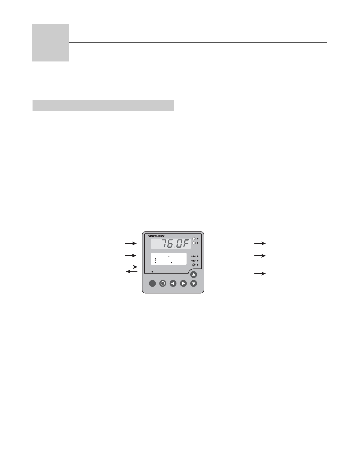
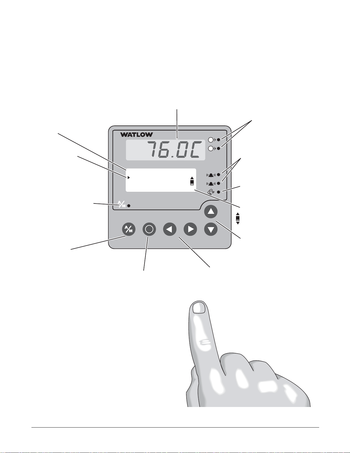
Figure 2.2 — Series F4P Displays and Indicator Lights.
1B
1A
2.2 ■ Operating from the Front Panel Watlow Series F4P
Upper Display
Displays Channel 1 actual
process values during
operation. Displays error
information if errors occur.
Lower Display
Guides setup and operation, displays
status information.
Cursor (>):
Points to the selected
parameter or present value.
Moves via the Up, Down,
Right and Left keys.
Auto/Manual Status Light
(Indicates mode status):
• Lit when in manual mode.
• Blinks for 10 seconds after
key pressed, while user
can change mode.
• Not lit during automatic
mode.
Auto/Manual Key
Press to toggle between auto
(closed-loop) and manual
(open-loop) control.
Information Key
Press for tips and definitions,
press again to return to the
original task.
Main Page___________
Go to Operations
Go to Setup
Go to Factory
i
F
4
1A
1B
1
Left and Right Keys
Press Right key to select the
item to the right of the cursor
(>) and proceed to the next
screen. Press Left key to
move left or exit.
2
Active Output Status Lights
Lit when the corresponding
controller channel output is
active.
Alarm Output Status Lights
Lit during an alarm state.
Communications Status
Light
Blinks when the controller
sends or receives data.
Scroll Bar
Indicates that more information exists above or below.
Use Up and Down keys.
Up and Down Keys
Press to move the cursor (>),
increase or decrease a value
or change a letter in a name.
To Clear an Alarm or Error
In an alarm condition, the alarm
status light will be lit. An alarm
message will appear on the Main
Page if configured to do so. To
silence the alarm, move the cursor
to the alarm message and press the
Right key. A message will confirm
the alarm silencing, and the alarm
status light will turn off.
After correcting the condition that
caused the error or alarm, return to
the error or alarm message on the
Main Page, and press the Right key
again. A message will confirm that
the alarm is unlatched.
Page 9

Watlow Series F4P Operating from the Front Panel ■ 2.3
Guided Programming
The Series F4P software guides users through most
tasks. To accomplish a task, simply proceed through the
sequence of parameters. For each parameter, choose the
appropriate option or establish the value, then press the
Right key to proceed to the parameter on the next
screen. The task is complete when you return to the initial menu.
1. Use
> or < to move the cursor to select an item
in a list.
2. Press the Right key
...
3. Enter the value and make a choice.
4. Press
. again.
5. Repeat until you return to the original list.
To change a specific, single parameter, proceed through
the parameter sequence without changing values until
you reach that parameter, then make your change. After
changing the value, you may back out of the sequence by
pressing the Left key or continue on through the
sequence by pressing the Right key. When you exit the
page, you must choose to Save Changes or Restore
Values.
.
.
.
Choose Cycle Time:__
>Variable Burst
Fixed Time
Choose Function:____
>Heat
Cool
Choose to Setup:____
>Control Output 1A
Control Output 2A
Main Page___________
Go to Operations
>Go to Setup
Go to Factory
Custom Main Page
The Main Page shows error messages; input and output
status; and allows access to controller software. You can
customize the Main Page to display chosen information
by going to the Setup Page, Custom Main Page Menu.
(See Chapter 4, Setup Page, for instructions.)
Auto and Manual Operation
The Series F4P controller can function as a static set
point controller (auto mode); or the user can directly
control the outputs (manual mode).
In the static set point mode, the Series F4P can only be
operated in a closed-loop configuration.
The Auto/Manual Indicator Light is on when the con-
troller is in manual mode. To toggle between manual and
auto mode, first press the Auto/Manual key
å , then con-
firm your selection in the lower display. The indicator
light will flash after you press
å until you confirm your
choice or 10 seconds have elapsed. While in manual mode
you can adjust the output power level for process outputs
or turn relay or open collector outputs on or off.
çWARNING: Only authorized and qualified personnel
should change the set point on the controller. Failure to
comply with these recommendations may result in damage to equipment and property and injury to personnel.
Static Set Point Control
When the Series F4P is in static set point mode:
• The Upper Display shows the actual process temperature of input 1.
• The Lower Display shows the default or user-configured Main Page.
To operate the Series F4P as a static set point controller,
select SP1 in the Main Page then use the Up and Down
keys to adjust the set point.
Limits may be placed on the set point in the Set Point
Low Limit and Set Point High Limit parameters (Setup
Page > Analog Input 1).
✔ Note: All control activity stops when you enter the
Setup Page, Analog Input, Digital Input, Control Output,
Alarm Output and Retransmit menus.
✔ Note: See also differential set point and ratio set
point.
Page 10

2.4 ■ Operating from the Front Panel Watlow Series F4P
• Process value must return to normal by
more than the hysteresis value to be
cleared.
• Configure alarm type, sides, hysteresis,
logic and set points.
• Correct cause of input error.
• Check the alarm output function.
• Alarm latched.
• Alarm output not configured correctly.
• Analog input(s) in error condition.
• Input may be in error condition.
• Alarm won’t clear.
(To clear the alarm, correct the
alarm condition. If the alarm
is latched, press
. with the
cursor at the alarm message on
the Main Page.)
• Turn on alarm annunciation.• Alarm annunciation is set to off.
• Exit Diagnostic mode.• Controller in Diagnostic mode.
• Configure alarm type, sides, hysteresis, logic
and set points.
• Alarm output not configured.
• Verify that silencing function is required.
Disable if not required.
• Alarm silencing is enabled.
Alarms
• Alarm won’t occur.
• Return controller to factory for repair.• Serial port of controller is defective.
• Verify or replace serial cable.• Serial cable is open or not wired correctly.
• Check converter box wiring and its documentation.
• Termination and/or pull up of bus required.
• Check computer communications port settings and verify PC communications.
• Computer communications port incorrectly
set up or defective.
• Converter must be half duplex.
• Check converter box wiring and settings.
• EIA-232 to EIA-485 converter incorrectly
set or wired.
• Verify correct connections and test wiring
paths.
• Communications wiring reversed, shorted
or open.
• Look for a break in the daisy chain.• Unit-to-unit daisy chain disconnected.
• Check Communications Setup Menu and set
to correct baud rate. Be sure it is Modbus
RTU protocol.
• Baud rate parameter incorrectly set or
incorrect protocol. Use Modbus RTU, 8 data
bits, no parity and 1 stop bit.
• Check Communications Setup Menu and set
to correct address.
• Address parameter incorrectly set.
Communications
• Unit will not
communicate.
• Measure power for required level. Check
part number for input power required.
• Check wire size.
• Check for bad connections.
• Input power incorrect.
• Check switches, fuses, breakers, interlocks,
limits, connectors, etc. for energized conditions and proper connection.
• Power to unit off.
• Fuse blown.
• Breaker tripped.
• Safety Interlock door switch, etc., activated.
• Separate system limit control latched.
• Wiring open.
Power
• No displays.
Corrective ActionProbable Cause(s)Indication
Troubleshooting
Page 11

Watlow Series F4P Operating from the Front Panel ■ 2.5
• Return to factory for evaluation.• Component failure.
Upper [Atod`]
Lower !Timeout x
(x is 1 to 3)
• Repair or replace sensor.
• Reverse sensor wiring connections.
Red lead is usually negative for tc.
• Set analog input to match sensor.
• Check sensor isolation. Inputs 2 and
3 are not isolated from each other.
• Sensor open.
• Sensor wired backwards. Display
decreases as process increases.
• Input type set to wrong sensor.
• Ground loop
Upper [SEnhi]
Lower !Input Sensor x+
(x is 1 to 3)
• Repair or replace sensor.
• Reverse sensor wiring connections.
Red lead is usually negative for tc.
• Set analog input to match sensor.
• Check sensor isolation. Inputs 2 and
3 are not isolated from each other.
• Sensor shorted (RTD).
• Sensor wired backwards. Display
decreases as process increases.
• Input type set to wrong sensor.
• Ground loop
Upper [SEnLo]
Lower !Input Sensor x-
(x is 1 to 3)
• Repair or replace sensor.
• Reverse sensor wiring connections.
Red lead is usually negative for tc.
• Set analog input to match sensor.
• Check sensor isolation. Inputs 2 and
3 are not isolated from each other.
• Sensor open.
• Sensor wired backwards. Display
decreases as process increases.
• Input type set to wrong sensor.
• Ground loop
Upper [A-dhi]
Lower !Input x AtoD+
(x is 1 to 3)
• Repair or replace sensor.
• Reverse sensor wiring connections.
Red lead is usually negative for tc.
• Set analog input to match sensor.
• Check sensor isolation. Inputs 2 and
3 are not isolated from each other.
• Sensor shorted (RTD).
• Sensor wired backwards. Display
decreases as process increases.
• Input type set to wrong sensor.
• Ground loop
Upper [A-dLO]
Lower !Input x AtoD
(x is 1 to 3)
Input Errors
(Upper Display shows error code
for input 1 only. Lower Display
shows additional errors. Input
2 and 3 error messages appear
in Lower Display. Alarm
Output Indicator is lit.)
• Tune PID set.
• Check power limit settings.
• Replace fuse or reset circuit breaker.
• Reposition sensor to accurately measure process.
• Check slidewire settings.
• PID values set incorrectly.
• Power limit set incorrectly.
• Open fuse or circuit breaker on energy
source.
• Incorrect sensor location in the process.
• Slidewire (if used) settings incorrect.
• Process will not reach set
point.
• Check operation mode. Automatic is
closed loop, manual is open loop.
• Check power limit settings.
• Check sensor, repair or replace.
• Check outputs, repair or replace.
• Check output settings.
• Check system wiring.
• Controller in manual operation mode
(percent power).
• Power limit set incorrectly.
• Thermocouple shorted.
• Shorted power switching device.
• Output set incorrectly (heat vs. cool).
• System wired incorrectly.
• Process runs away (too high or
too low).
• Check power limit settings.
• Tune PID set.
• Use correct PID set.
• Power limit set incorrectly.
• PID values set incorrectly.
• Incorrect PID set active.
Controllability
• Process will not
stabilize.
• Check alarm logic setting and output
wiring.
• Alarm logic setting incorrect or output
wired incorrectly.
• Alarm output action is
reversed.
Corrective ActionProbable Cause(s)Indication
Page 12

2.6 ■ Operating from the Front Panel Watlow Series F4P
• Add power line filter for input power.
• Return controller to factory for repair.
• Noise on power line.
• Component failure.
• Checksum error in
Cycle device power.
• Press any key. All parameters will default.
• Module changed.• Module change. Defaults will
occur. Accept with any key.
• Replace incorrect module with retransmit module.
• Wrong module in retransmit 2 slot.• Retransmit 2 Module Error!
Only process modules
supported.
• Replace incorrect module with retransmit module.
• Wrong module in retransmit 2 slot.• Retransmit 1 Module Error!
Only process modules
supported.
• Check for correct installation of module.
• Module not seated correctly in slot.• Verify the module.
• Check for correct installation of module.
• Module installed incorrectly or in
wrong slot.
• Module not allowed
• Replace output module.• Output module failure.• Output 1A
• Output 1B
• Output 2A
• Output 2A
• Move module to correct input slot.
• Move module to correct input slot.
• Input module 2 or 3 is in input 1 slot.
• Input module 1 is in input 2 or 3 slot.
• Verify Input 1
• Verify Input 2 or 3
• Replace module or return controller
to factory for repair
• Amodule has lost its programming ID. • Incorrect ID!
• Contact factory for further information and diagnosis.
• Component failure. • Unknown Error!
Record this number. Contact
the factory.
• Add filter to AC power line and verify
unit is power by AC voltage.
• Controller can’t detect zero cross point.
Noise is present on AC power line or
unit is not powered by AC voltage.
• Zero Cross Failure!
Switched to Fixed
Time control.
System Errors
(Upper Display shows error
numbers. Lower Display messages indicate cause and
action to take.)
• Check wiring and process valve for
compatibility.
• Process valve is wired incorrectly or incompatible.
Upper
Lower Slidewire time out
• Increase slidewire time out value.
• Replace process valve.
• Increase slidewire time out value.
• Check wiring and process valve for
compatibility.
• Slidewire time out value set too short.
• Slidewire valve is stuck or not
responding.
• Process valve is wired incorrectly or incompatible.
Upper
Lower Slidewire time out
• Return to factory for evaluation.• Component failure.
Upper
Lower !Input x Error
(x is 1 to 3)
Corrective ActionProbable Cause(s)Indication
Page 13

Watlow Series F4P Operating from the Front Panel ■ 2.7
• Repair heating/cooling circuits.
• Check circuit breakers, switches,
heater elements, compressor.
• Heater/cooling non-functional.
• Replace sensor.• Sensor shorted.
• Replace relay.• Output relay open or shorted.
• Place sensor near source.• Sensor not properly located
• Check all wiring and components.
• Turn the controller off, then on again.
Open Loop Detect
(Upper Display shows error
code for input 1 only. Lower
Display shows additional
errors.
Upper: [oPLP`]
Lower: Open Loop
• Return controller to factory for repair.• Controller has failed.• Flash memory Failed.
Return controller to the
Factory.
• Return controller to factory for repair.• Controller has failed.• RAM Test Failed!
Return controller to the
Factory.
• Turn the controller off, then on again.
If problem persists, power line filter is
required.
• Power line noise has corrupted memory.• Checksum Error!
Parameter memory.
• Checksum Error!
Unit Config memory
• Checksum Error!
Profile memory.
• Normal operation following flash update of firmware.
• Controller firmware has been updated.• Firmware change.
Parameters are initializing.
• Return controller to factory for repair.• Power was interrupted during a flash
update or there is a component failure.
• Flash Memory Failed!
Return controller to the
Factory.
• Return controller to factory for repair.• Component failure.• RAM Test Failed!
Return controller to the
Factory.
• Should not appear in the field. Call
the factory if you get this message.
• Controller powered up for the first time.• First power-up.
Parameters are initializing.
• This is normal upon module change.• Input or output module was changed.• Module change.
All parameters are initializing.
Corrective ActionProbable Cause(s)Indication
Page 14

2.8 ■ Operating from the Front Panel Watlow Series F4P
Notes:
Page 15

Watlow Series F4P Operations Page ■ 3.1
Chapter Three: Operations Page
Alarm Set Points . . . . . . . . . . . . . . . . . . . . . . . . . . .3.1
Autotune PID . . . . . . . . . . . . . . . . . . . . . . . . . . . . . .3.2
Edit PID . . . . . . . . . . . . . . . . . . . . . . . . . . . . . . . . . .3.2
Multiple PID Sets . . . . . . . . . . . . . . . . . . . . . . . . . . .3.3
Cascade Tuning . . . . . . . . . . . . . . . . . . . . . . . . . . . .3.3
This chapter explains how to establish alarm set points,
autotune and manually tune and establish cascade control through the Operations Page of the software.
To configure the alarm outputs, go to the Setup Page of
the software (see related information in the Parameters
Chapter).
For the alarm clearing procedure, go to the Troubleshooting Alarms and Errors table in the Navigation and
Operating from the Front Panel Chapter.
For background information about alarms; proportional,
integral and derivative control; and cascade, see the Features Chapter.
Alarm Set Points
The Series F4P includes two alarm outputs, which can be
programmed as process, deviation or rate alarms.
Process alarms notify the operator when process values
exceed or fall below Alarm Low and Alarm High Set
Points. Deviation alarms notify the operator when the
process has deviated from the set point beyond the deviation limits. Rate alarms are triggered by a change in
temperature or process value that is faster than the selected rate.
For more information, see the Features Chapter. To set
up the alarms, see the Setup Chapter.
Alarm set points are the points at which alarms switch
on or off, depending on the alarm setting. Alarm set
points can be viewed or changed in the Alarm Set Point
Menus (Operations Page).
The Alarm High Set Point defines the high value that,
if exceeded, will trigger an alarm. This value must be
higher than the alarm low set point and lower than the
high limit of the sensor range.
The Alarm Low Set Point defines the low value that, if
exceeded, will trigger an alarm. This value must be lower
than the alarm high set point and higher than the low
limit of the sensor range.
The Alarm Low Deviation defines the deviation value
on the low side of set point at which the alarm will be
triggered.
The Alarm High Deviation defines the deviation value
on the high side of set point at which the alarm will be
triggered.
✔ Note: You may want to set up the alarms with names
that will identify the alarm conditions. See the Setup
Page.
To Clear an Alarm or Error
In an alarm condition, the alarm status light will be lit.
An alarm message will appear on the Main Page if configured to do so. To silence an alarm, the Silencing option
in the Alarm Output menu (Setup Page) must be enabled. To silence the alarm, move the cursor to the alarm
message and press the Right key. Amessage will confirm
the silencing of the alarm, and the alarm status light will
turn off. After correcting the condition that caused the
error or alarm, return to the error or alarm message on
the Main Page, and press the Right key again. Amessage
will confirm that the alarm is unlatched.
3
Page 16

3.2 ■ Operations Page Watlow Series F4P
Autotune PID
In autotuning, the controller automatically selects the
PID parameters for optimal control, based on the thermal response of the system. In the Series F4P, five sets of
PID values are available. Default PID values exist for all
PID sets, although these values typically do not provide
optimal control. PID values can be auto-tuned or adjusted manually. When autotuning is complete, the PID values will be stored in the Edit PID Menu.
Set point changes for remote, ratio and differential control are ignored until autotuning is complete.
Autotuning Procedure
Autotuning is initiated from the Operation Menu.
1. Before initiating auto-tune, go to the System Menu
(Setup Page), and establish the Autotune Set Point
to a percentage of set point. This percentage is based
on your knowledge of the system and how much
overshoot or undershoot there is likely to be in on-off
control.
Select to display Tune Status in the Custom Main
Page Menu.
2. Go to the Main Page and adjust set point.
3. Go to the Autotune PID Menu (Operations Page) and
choose the PID set in which to store the values. You
must exit back to Main Page with the left arrow. A
message will be displayed on the Main Page during
the autotuning process.
4. When autotuning is complete, the controller will
store the values for optimum control in the specified
PID set.
For additional information about autotuning and proportional, integral and derivative control, see the Features
Chapter.
✔ Note: While the controller is autotuning, only the Op-
eration Page of the software can be entered.
ç
CAUTION: Choose an autotune set point value that will
protect your product from possible damage from overshoot
or undershoot during the autotuning oscillations. If the
product is sensitive, select the autotune set point very
carefully to prevent product damage.
Edit PID
The Edit PID Menu is useful when Auto-tune PID does
not provide adequate control. Each of the PID parameters can be adjusted manually:
Proportional Band: Define a band for PID control, entered in degrees or units. Lower values increase gain,
which reduces droop but can cause oscillation. Increase
the proportional band to eliminate oscillation.
Integral (Reset): Define the integral time in minutes
per repeat; define reset in repeats per minute. Set repeats per minute if units are U.S.; minutes per repeat if
units are SI.
Derivative (Rate): Define the derivative (rate) time in
minutes. Large values prevent overshoot but can cause
sluggishness. Decrease if necessary.
Dead Band: Define the dead band in degrees or units.
Heating dead band shifts the set point down. Cooling
dead band shifts the set point up. For more information,
see the Features Chapter.
For background information, see Chapter 7, Features.
Manual Tuning Procedure
1. Apply power to the Series F4P and establish a set
point on the Main Page.
2. Establish Cycle Time in the Control Output Menu
(Setup Page), as required. Typical cycle times are 1.0
second for an SSR and 5.0 seconds for a mechanical
relay. Faster cycle times sometimes achieve the best
system control. However, if a mechanical contactor or
solenoid is switching power to the load, a longer cycle time may be desirable to minimize wear on the
mechanical components. Experiment until the cycle
time is consistent with the desired quality of control.
3. Go to the Edit PID Menu (Operations Page), and
choose the channel and PID set. Establish values for
the PID parameters: Proportional Band, 5; Integral
(Reset), 0; Derivative (Rate), 0; and Autotune, Tune
Off. Tuning begins when you choose a PID set.
4. When the system stabilizes, watch the value of Input
1 on the Main Page. If this value fluctuates, increase
the proportional band setting until it stabilizes. Adjust the proportional band in 3° to 5° increments, allowing time for the system to stabilize between adjustments.
5. When Input 1 has stabilized, watch the percent power on the Main Page. It should be stable, ±2%. At
this point, the process temperature should also be
stable, but it will exhibit droop (stabilized below set
point). The droop can be eliminated with integral (reset).
Page 17

Watlow Series F4P Operations Page ■ 3.3
6. Start with an integral setting of 99.9 minutes and allow 10 minutes for the process temperature to get to
set point. If it has not, decrease the setting by half
and wait another 10 minutes. Then halve the setting
again and wait another 10 minutes until the process
value equals the set point. If the process becomes unstable, the integral value is too small. Increase it until the process stabilizes.
7. Increase Derivative/Rate to 0.10 minute. Then increase the set point by 11° to 17°C. Watch the system's approach to the set point. If the process value
overshoots the set point, increase Derivative/Rate to
0.50 minute.
Increase the set point by 11° to 17°C and watch the
approach to the new set point. If you increase
Derivative/Rate too much, the approach to the set
point will be very sluggish. Repeat as necessary until
the system rises to the new set point without overshoot or sluggishness.
For additional information about the burst fire feature,
manual tuning and PID control, see the Features Chapter.
Multiple PID Sets
Environmental chambers, ovens and furnaces typically
have different thermal requirements at high and low
temperatures or pressures. To accommodate this, the Series F4P can store five different PID sets.
Multiple Tuning Procedure
To autotune multiple PID sets, follow the Autotuning
procedure above for each PID set. When autotuning is
finished for one set, proceed with another.
Cascade
Cascade control is available on enhanced (F4P _ - _ _ AB
- _ _ _ _) Series F4P controllers. For background information about cascade control, see the Features Chapter.
Select cascade control through the Analog Input 3 Menu
(Setup Page), and choose Process Cascade or Deviation
Cascade. To set the range for the inner loop set point,
Process Cascade uses Low and High Range settings that
are independent of set point; Deviation Cascade uses Deviation Low and High settings that are deviations from
the primary set point.
When tuning a cascade system, the inner loop must be
tuned first. The inner loop comprises outputs 1A and 1B
and the Analog Input 1 sensor, which usually measures
the energy source temperature. The output device controls a power switching device, which in turn switches
the heating and cooling. The set point for the inner loop
is generated by the outer loop. For Process Cascade, this
will have a range between the Cascade Low Range and
Cascade High Range.
Cascade Setup Procedure
1. First, configure Analog Input 3, Cascade Low Range
and Cascade High Range.
Go to the Analog Input 3 Menu (Setup Page). Choose
Process or Deviation Cascade. Deviation Cascade references Channel 1 set point allowing a range above and
below the current control set point. For Process Cascade
control of a heat/cool or cool only system, set the Cascade
Low Range to a value slightly lower than the lowest
temperature desired in the chamber. For heat-only systems, set the Cascade Low Range to a value slightly lower than the ambient temperature; otherwise the heat
output will never turn fully off.
For heat/cool or heat only systems , set the Cascade
High Range to a value slightly higher than the highest
temperature desired in the chamber. For cool-only
systems, set the Cascade High Range to a value slightly
higher than the ambient temperature; otherwise the
cooling will never fully turn off.
2. Next, configure the controller to tune and display data
for the outer loop. To view Inner Loop Set Point in the
upper display, go to the Setup Page, Custom Main Page
Menu, select the Inner Set point as one of the parameters, P1 to P16, to be displayed in the Main Page.
To also view Analog Input 3 in the upper display, go to
the Setup Page, Process Display Menu, and choose Alternating. Under Set Display Time, choose a duration
for the display of the Input 1 and Input 3 variables.
Cascade Autotuning Procedure
1. Go to Setup Page, Custom Main Page Menu. Choose
Tune Status 1 and Tune Status 2 to appear as 2 of the
16 parameters that can be displayed on the Main Page.
The Main Page will now display the status of the autotuning process.
2. Autotune the inner loop. Go to the Autotune PID Menu
(Operations Page), and select Cascade Inner-loop.
Choose Cascade Inner Loop PID Set 1 to 5, where PID
values will be stored after autotuning. Autotuning begins when you choose the PID set. While autotuning,
the F4 controller will control the energy source in an
on-off mode to a temperature equal to the Cascade High
Range setting x Channel 1 Autotune Set Point. For best
results, use proportional control only on the inner loop.
Page 18

3.4 ■ Operations Page Watlow Series F4P
3. Next, autotune the outer loop. Go to the Autotune PID
Menu (Operations Page). Choose Cascade Outer Loop,
then choose Outer Loop PID set 1 to 5, where PID values will be stored after autotuning. Autotuning begins
when you choose the PID set. While autotuning, the
outer loop will be controlled in an on-off mode at a set
point equal to static set point x Ch 1 Autotune Set
Point. In most cases, the autotuning feature will tune
for acceptable control. If not, manually tune the outer
loop (step 4 below). Before manually tuning, record the
values generated by the autotuning feature.
4. To manually tune the outer loop, go to the Edit PID
Menu (Operations Page). Choose Cascade Outer Loop,
then choose Outer Loop PID set 1 to 5. Begin manual
tuning by setting the Proportional Band to 5, Integral
(Reset) to 0, and Rate to 0. Establish the desired set
point and let the system stabilize. When the system
stabilizes, watch the Inner Loop Set Point on the Main
Page. If this value fluctuates, increase the proportional
band until it stabilizes. Adjust the proportional band
in 3° to 5° increments, allowing time for the system to
stabilize between adjustments.
5. When Input 1 has stabilized, watch the percent power
on the Main Page. It should be stable, ±2%. At this
point, the process temperature should also be stable,
but it will exhibit droop (stabilized below set point).
The droop can be eliminated with Integral (reset).
6. Start with an integral setting of 99.9 minutes, and allow 10 minutes for the process temperature to come up
to set point. If it has not, decrease the setting by half
and wait another 10 minutes. Then halve the setting
again and wait another 10 minutes until the process
value equals the set point. If the process becomes
unstable, the integral value is too small. Increase it
until the process stabilizes.
Page 19

Watlow Series F4P Setup Page ■ 4.1
Chapter Four: Setup Page
Parameter Setup Order . . . . . . . . . . . . . . . . . . . . . .4.1
Customizing the Main Page . . . . . . . . . . . . . . . . . .4.2
Static Messages . . . . . . . . . . . . . . . . . . . . . . . . . . .4.2
4
This chapter explains how to configure the controller
software through the Setup Page menus. Setup Page parameters affect the way the controller responds to your
application, which parameters and functions are visible
in other pages, and the way information is displayed on
the Main Page. Set up the controller properly to provide
a sound foundation for settings in other pages.
For ranges, defaults and other information about specific
parameters, see the Parameters Chapter. Record your
settings in the Parameter Setup Record, also in that
chapter.
For background information about inputs, outputs,
alarms and other features, see the Features Chapter.
Parameter Setup Order
Initial configuration of the Series F4P is best done in the
following order:
1. Go to the System Menu (Setup Page) to configure:
• PID units — SI (Integral, Derivative) or U.S. (Reset, Rate);
• Celsius or Fahrenheit scales;
• display of units in the controller’s upper display;
• Autotune set point;
• open-loop detection warnings; and
• controller response to a power outage.
2. Go to other menus on the Setup Page to configure:
• Analog Input x (1 to 3);
• Digital Input x (1 to 4);
• Control Output x (1A, 1B);
• Alarm Output x (1 or 2);
• Retransmit Output x (1 or 2);
• Communications; and
• Custom Main Page and Custom Messages.
3. Go to the Operations Page to tune the PID sets.
4. Go to the Operations Page to set the alarm set
points.
After this initial configuration, the most frequent
changes will be to the Operations Page (alarm set points
and PID sets).
If the Series F4P is already installed in an environmental chamber, oven, furnace or other equipment, most parameters will already be configured and access to the
Setup Page may be limited (see Chapter 5, Factory
Page).
Changing Setup Page parameters may change other parameters. In some cases, a change in one parameter will
affect the defaults of others. To see how all the pages,
menus and parameters are grouped, see the software
map on the inside back cover of this manual.
✔ Note: For more information about how parameter set-
tings affect the controller’s operation, see the Features
Chapter.
çWARNING: Only authorized and qualified personnel
should change the factory-default settings, which may
cause changes in other settings. Failure to comply with
this recommendation may result in damage to equipment
and property and injury to personnel.
Page 20

4.2 ■ Setup Page Watlow Series F4P
Customizing the Main Page
Up to 16 lines can be added to the Main Page to display
status and information from the controller.
Go to the Custom Main Page Menu on the Setup Page.
The first screen will prompt you to choose one of the 16
lines to customize. "P1 Parameter" is the first line; "P16
Parameter" is the 16th. After choosing this line by pressing ., select a parameter to monitor.
Your choices are listed under Custom Main Page in the
Setup Page Parameter Table in this chapter.
Figure 4.2 — Example of Parameters on the Custom Main
Page.
Input1 26°C
PID Set 1
Power1A 0%
Power1B 55%
DigitalIn _234
Choose P:1 Display_ _
>None
Input 1 Value ■
Input 1 Value bar ▼
Choose:_ _ _____
>P1 Parameter
P2 Parameter ■
P3 Parameter ▼
Static Messages
Digital inputs can be configured to display a message
that the user enters. The message is displayed on the
Main Page when the digital input is active.
This feature could, for instance, display “DOOR OPEN” if
an oven door is not closed all the way.
Page 21

Watlow Series F4P Factory Page ■ 5.1
Chapter Five: Factory Page
Security . . . . . . . . . . . . . . . . . . . . . . . . . . . . . . . . . .5.1
Diagnostics . . . . . . . . . . . . . . . . . . . . . . . . . . . . . . .5.3
Calibration . . . . . . . . . . . . . . . . . . . . . . . . . . . . . . . .5.3
5
Security
The Series F4P allows users to set separate security
levels for the Static Set Point prompt on the Main Page,
for all menus on the Operations Page, as well as for the
Setup Page and Factory Page. Four levels of security are
available:
• Full Access (operators can enter and change
settings);
• Read Only (operators can read but not change
settings);
• Password (operators can enter and change settings
after entering a password); and
• Hidden (operators cannot see the menu or page — it
is not displayed). Set Point settings cannot be
Hidden.
✔ Note: Full Access is the default for all menus. Unless
you change the level of access, operators will be able to
read and change every setting in every menu in the
Series F4P software.
How to Set Lockout Levels
Using the Lockout Menu, you can limit access to the
following menus and pages:
• Set Point on Main Page
• Operations Page Autotune PID
• Operations Page Edit PID
• Operations Page Alarm Set Point
• Setup Page
• Factory Page
Choose the item to lock out, press .. and choose the level
of access: Full, Read Only, Password or Hidden. If you
choose Password, you must set the password — see
below.
✔ Note: For more information about how parameter
settings affect the controller’s operation, see the Features
Chapter.
ç CAUTION: Only authorized and qualified personnel
should be allowed to perform preventive and corrective
maintenance on this unit.
…Lock>Autotune PID___
Full Access
Read Only
>Password
.
…Factory>Set Lock___
Set Point
>Oper. Autotune PID ■
Oper. Edit PID ▼
.
Main>Factory________
>Set Lockout
Diagnostic
Test
Page 22

5.2 ■ Factory Page Watlow Series F4P
Enter a Password
If you try to set password security before any password
has been established, a pop-up message will give you the
opportunity to enter one. Use the . , , , > and < keys
to enter a four-character password, which can consist of
letters, numbers or both. After entering and confirming
the password, re-enter the chosen menu or page and
select Password Security. Record your password and keep
it secure.
Confirm Password:
_ _ _ _
▲▼ Adjusts Char
< Back >Next
Enter New Password:
_ _ _ _
▲▼ Adjusts Char
< Back >Next
Must reset lock
after setting the
password
■ ■ ■ Press any key!■ ■ ■
>
No Password!
Set Password?
▼ No ▲ Yes
■ ■ ■ ■ ■ ■ ■ ■ ■ ■ ■ ■ ■ ■
Use a Password
To enter a password-protected area, users must enter the
password. If an incorrect password is entered, a pop-up
message will tell you it is invalid and you may try again.
When the password is correct, choose again to enter the
menu or page of your choice.
Change a Password
The Change Password parameter is near the end of the
list under Set Lockout on the Factory Page. To change a
password, you must first enter the old password for
confirmation.
Enter Password:
_ _ _ _
▲▼ Adjusts Char
< Back >Next
.
…Factory>Set Lock___
Setup ▲
Factory ■
>Change password ▼
Invalid, Re-Enter:____
▲▼ Adjusts Char
< Back >Next
Page 23

Watlow Series F4P Factory Page ■ 5.3
Diagnostics
Diagnostic Menu parameters (on the Factory Page)
provide information about the controller unit that is
useful in troubleshooting. For example, the Out1A
parameter will identify what type of output has been
selected for Output 1A.
Select the parameter by pressing the Right Key . . The
information will appear on the Lower Display.
Some of the parameters in the Diagnostic Menu provide
information for factory use only.
To reset all parameters to their original factory values,
use the Full Defaults parameter under the Test Menu.
Test
This menu allows you to test outputs, test the displays
(upper, lower and status lights), and cause the controller
to revert to the defaults set at the factory. Reverting to
factory defaults will erase all preset software and the
controller will return to U.S. PID units (Reset and Rate)
and the Fahrenheit temperature scale.
Calibration
The Calibration Menu on the Factory Page allows
calibration of inputs and outputs. Calibration procedures
should be done only by qualified technical personnel with
access to the equipment listed in each section.
Before beginning calibration procedures, warm up the
controller for at least 20 minutes.
Restore Factory Values
Each controller is calibrated before leaving the
factory. If at any time you want to restore the factory
input calibration values, use the last parameters in the
menu: Restore Input x (1 to 3) Calibration. Press ... No
special equipment is necessary.
Thermocouple Input Procedure
Equipment
•Type J reference compensator with reference
junction at 32°F/0°C, or type J thermocouple
calibrator to 32°F/0°C.
• Precision millivolt source, 0 to 50mV minimum
range, 0.002mV resolution.
Input x (1 to 3) Setup and Calibration
Inputs 2 and 3 appear only if the controller is the
enhanced version (F4P _ - _ _ AB - _ _ _ _).
1. Connect the correct power supply to terminals 1, 2
and 3 (see the Wiring Chapter and the Appendix).
2. Connect the millivolt source to input 1 terminals 62
(-) and 61 (+), input 2 terminals 58 (-) and 57 (+), or
input 3 terminals 56 (-) and 55 (+), with copper wire.
3. Enter 50.000mV from the millivolt source. Allow at
least 10 seconds to stabilize. Press the Right Key .
once at the Calibrate Input x (1 to 3) prompt
(Factory Page). At the 50.00mV prompt press . once
and to store 50.00mV press the Up Key > once.
4. Enter 0.000mV from the millivolt source. Allow at
least 10 seconds to stabilize. At the 0.00mV prompt
press . once and to store 0.00mV press > once.
5. Disconnect the millivolt source and connect the
reference compensator or thermocouple calibrator to
input 1 terminals 62 (-) and 61 (+), input 2 terminals
58 (-) and 57 (+), or input 3 terminals 56 (-) and 55
(+). With type J thermocouple wire, if using a
compensator, turn it on and short the input wires.
When using a type J calibrator, set it to simulate
32°F/0°C. Allow 10 seconds for the controller to
stabilize. Press . once at the Calibrate Input x (1 or
2) prompt (Factory Page). At the 32°F Type J prompt
press . once and to store type J thermocouple
calibration press > once.
6. Rewire for operation and verify calibration.
Page 24

5.4 ■ Factory Page Watlow Series F4P
RTD Input Procedure
Equipment
•1kΩ decade box with 0.01Ω resolution.
Input x (1 to 3) Setup and Calibration
1. Connect the correct power supply to terminals
1, 2 and 3 (see the Wiring Chapter and the
Appendix).
2. Short Input 1 terminals 60, 61 and 62; Input 2
terminals 54, 57 and 58; or Input 3 terminals
52, 55 and 56 together with less than 0.1Ω.
Press the Right Key . once at the Calibrate
Input x (1 to 3) prompt. At the Ground prompt
press . once and to store ground input press
the Up Key > once.
3. Short Input 1 terminals 60 and 61; Input 2
terminals 54 and 57; or Input 3 terminals 52
and 55 together with less than 0.5Ω. Press .
once at the Calibrate Input x (1 to 3) prompt.
At the Lead prompt press . once and to store
lead resistance press > once.
4. Connect the decade box to Input 1 terminals 60
(S2), 61 (S1) and 62 (S3); Input 2 terminals 54
(S2), 57 (S1) and 58 (S3); or Input 3 terminals
52 (S2), 55 (S1) and 56 (S3), with 20- to 24gauge wire.
5. For 100Ω RTD, enter 15.00Ω. For 500Ω or 1kΩ
RTD, enter 240.00Ω. Allow at least 10 seconds
to stabilize. Press . once at the Calibrate
Input x (1 to 3) prompt (Factory Page). At the
15.00Ω or 240.00Ω* RTD prompt press . once
and to store the 15.00Ωor 240.00Ωinput press >
once.
6. For 100Ω RTD, enter 380.00Ω. For 500Ω or 1kΩ
RTD, enter 6080.00Ω. Allow at least 10 seconds
to stabilize. Press . once at the Calibrate
Input x (1 to 3) prompt. At the 380.0Ω or
6080.00Ω* RTD prompt press . once and to
store the 380.00Ω or 6080.00Ω input press >
once.
7. Rewire for operation and verify calibration.
Slidewire Feedback Input Procedure
Equipment
•1kΩ decade box with 0.01Ω resolution.
Input 3 Setup and Calibration
Input 3 appears only if the controller is the enhanced
version (F4P _ - _ _ AB - _ _ _ _).
1. Connect the correct power supply to terminals
1, 2 and 3 (see the Wiring Chapter and the
Appendix).
2. Connect the decade box to Input 3 terminals 55
(S1) and 56 (S3), with 20- to 24-gauge wire.
3. Enter 15.00Ω. on the decade box. Allow at least
10 seconds to stabilize. Press . once at the
Calibrate Input 3 prompt (Factory Page). At the
15.00Ω SlWr prompt press . once and to store
the 15.00Ω input press > once.
4. Enter 1000.00Ω. from the decade box. Allow at
least 10 seconds to stabilize. Press . once at
the Calibrate Input 3 prompt. At the 1000.00Ω
SlWr prompt press . once and to store the
380.00Ω or 6080.00Ω input press > once.
5. Rewire for operation and verify calibration.
Voltage Process Input Procedure
Equipment
• Precision voltage source, 0 to 10V minimum range,
with 0.001V resolution.
Input x (1 to 3) Setup and Calibration
Inputs 2 and 3 appear only if the controller is the
enhanced version (F4P _ - _ _ AB - _ _ _ _).
1. Connect the correct power supply to terminals 1, 2
and 3 (see the Wiring Chapter and the Appendix).
2. Connect the voltage source to input 1 terminals 59
(+) and 62 (-), input 2 terminals 53 (+) and 58 (-) or
input 3 terminals 51 (+) and 56 (-).
3. Enter 0.000V from the voltage source to the
controller. Allow at least 10 seconds to stabilize.
Press the Right Key . once at the Calibrate Input 1
prompt. At the 0.000V prompt press . once and to
store the 0.000V input press the Up Key > once.
✔
NOTE:
You need the equipment listed and technical skills.
Controllers come calibrated from the factory. Recalibrate
only for other agency requirements or if temperatures
aren’t accurate as verified by another calibrated
instrument.
*The tenth digit of your model number, F4XX-XXXX-
X
XXX, determines what prompts appear and what
input resistance values to use for RTD calibration. Refer
to the Ordering Information in the Appendix.
Page 25

Watlow Series F4P Factory Page ■ 5.5
4. Enter 10.000V from the voltage source to the
controller. Allow at least 10 seconds to stabilize.
Press . once at the Calibrate Input 1 prompt. At
the 10.000V prompt press . once and to store the
10.000V input press > once.
5. Rewire for operation and verify calibration.
Current Process Input Procedure
Equipment
• Precision current source, 0 to 20mA range, with
0.01mA resolution.
Input x (1 to 3) Setup and Calibration
Inputs 2 and 3 appear only if the controller is the
enhanced version (F4P _ - _ _ AB - _ _ _ _).
1. Connect the correct power supply to terminals 1, 2
and 3 (see the Wiring Chapter and the Appendix).
2. Connect the current source to input 1 terminals 60
(+) and 62 (-), input 2 terminals 54 (+) and 58 (-), or
input 3 terminals 52 (+) and 56 (-).
3. Enter 4.000mA from the current source to the
controller. Allow at least 10 seconds to stabilize.
Press the Right Key . once at the Calibrate Input 1
prompt. At the 4.000mAprompt press . once and to
store 4.000mA press the Up Key > once.
4. Enter 20.000mA from the current source to the
controller. Allow at least 10 seconds to stabilize.
Press . once at the Calibrate Input 1 prompt. At
the 20.000mA prompt press . once and to store
20.000mA press > once.
5. Rewire for operation and verify calibration.
Process Output Procedure
Equipment
• Precision volt/ammeter with 3.5-digit resolution.
Output 1A Setup and Calibration
1. Connect the correct power supply to terminals 1, 2
and 3 (see the Wiring Chapter and the Appendix).
Milliamperes
2. Connect the volt/ammeter to terminals 42 (+) and 43
(-).
3. Press the Right Key . at the Calibrate Output 1A
prompt. At the 4.000mAprompt press . once. Use
the Up Key > or the Down Key < to adjust the
display to the reading on the volt/ammeter. The
controller should stabilize within one second. Repeat
until the volt/ammeter reads 4.000mA. Press . to
store the value.
4. Press the Right Key . at the Calibrate Output 1A
prompt. At the 20.000mAprompt press . once. Use
the Up Key > or the Down Key < to adjust the
display to the reading on the volt/ammeter. The
controller should stabilize within one second. Repeat
until the volt/ammeter reads 20.000mA. Press . to
store the value.
Volts
5. Connect the volt/ammeter to terminals 44 (+) and 43
(-).
6. Press the Right Key . at the Calibrate Output 1A
prompt. At the 1.000V prompt press . once. Use the
Up Key > or the Down Key < to adjust the display
to the reading on the volt/ammeter. The controller
should stabilize within one second. Repeat until the
volt/ammeter reads 1.000V. Press . to store the
value.
7. Press the Right Key . at the Calibrate Output 1A
prompt. At the 10.000V prompt press . once. Use
the Up Key > or the Down Key < to adjust the
display to the reading on the volt/ammeter. The
controller should stabilize within one second. Repeat
until the volt/ammeter reads 10.000V. Press . to
store the value.
8. Rewire for operation and verify calibration.
Output 1B Setup and Calibration
1. Connect the correct power supply to terminals 1, 2
and 3 (see the Wiring Chapter and the Appendix).
Milliamperes
2. Connect the volt/ammeter to terminals 39 (+) and 40
(-).
3. Press the Right Key . at the Calibrate Output 1B
prompt. At the 4.000mAprompt press . once. Use
the Up Key > or the Down Key < to adjust the
display to the reading on the volt/ammeter. The
controller should stabilize within one second. Repeat
until the volt/ammeter reads 4.000mA. Press . to
store the value.
4. Press the Right Key . at the Calibrate Output 1B
prompt. At the 20.000mAprompt press . once. Use
the Up Key > or the Down Key < to adjust the
display to the reading on the volt/ammeter. The
controller should stabilize within one second. Repeat
until the volt/ammeter reads 20.000mA. Press . to
store the value.
Volts
5. Connect the volt/ammeter to terminals 41 (+) and 40
(-).
6. Press the Right Key . at the Calibrate Output 1B
prompt. At the 1.000V prompt press . once. Use the
Up Key > or the Down Key < to adjust the display
to the reading on the volt/ammeter. The controller
should stabilize within one second. Repeat until the
volt/ammeter reads 1.000V. Press . to store the
value.
Page 26

5.6 ■ Factory Page Watlow Series F4P
7. Press the Right Key . at the Calibrate Output 1B
prompt. At the 10.000V prompt press . once. Use
the Up Key > or the Down Key < to adjust the
display to the reading on the volt/ammeter. The
controller should stabilize within one second. Repeat
until the volt/ammeter reads 10.000V. Press . to
store the value.
8. Rewire for operation and verify calibration.
Retransmit Output Procedure
Equipment
• Precision volt/ammeter with 3.5-digit resolution.
Retransmit 1 Setup and Calibration
1. Connect the correct power supply to terminals 1, 2
and 3 (see the Wiring Chapter and the Appendix).
Milliamperes
2. Connect the volt/ammeter to terminals 50 (+) and 49
(-).
3. Press the Right Key . at the Calibrate
Rexmit 1 prompt. At the 4.000mAprompt press .
once. Use the Up Key > or the Down Key < to
adjust the display to the reading on the
volt/ammeter. The controller should stabilize within
one second. Repeat until the volt/ammeter reads
4.000mA. Press . to store the value.
4. Press the Right Key . at the Calibrate Rexmit 1
prompt. At the 20.000mAprompt press . once. Use
the Up Key > or the Down Key < to adjust the
display to the reading on the volt/ammeter. The
controller should stabilize within one second. Repeat
until the volt/ammeter reads 20.000mA. Press . to
store the value.
Volts
5. Connect the volt/ammeter to terminals 48 (+) and 49
(-).
6. Press the Right Key . at the Calibrate Rexmit 1
prompt. At the 1.000V prompt press . once. Use the
Up Key > or the Down Key < to adjust the display
to the reading on the volt/ammeter. The controller
should stabilize within one second. Repeat until the
volt/ammeter reads 1.000V. Press . to store the
value.
7. Press the Right Key . at the Calibrate Rexmit 1
prompt. At the 10.000V prompt press . once. Use
the Up Key > or the Down Key < to adjust the
display to the reading on the volt/ammeter. The
controller should stabilize within one second. Repeat
until the volt/ammeter reads 10.000V. Press . to
store the value.
8. Rewire for operation and verify calibration.
Retransmit 2 Setup and Calibration
1. Connect the correct power supply to terminals 1, 2 and
3 (see the Installing and Wiring Chapter and the
Appendix).
Milliamperes
2. Connect the volt/ammeter to terminals 47 (+) and 46
(-).
3. Press the Right Key . at the Calibrate Rexmit 2
prompt. At the 4.000mAprompt press . once. Use
the Up Key > or the Down Key < to adjust the
display to the reading on the volt/ammeter. The
controller should stabilize within one second. Repeat
until the volt/ammeter reads 4.000mA. Press . to
store the value.
4. Press the Right Key . at the Calibrate Rexmit 2
prompt. At the 20.000mAprompt press . once. Use
the Up Key > or the Down Key < to adjust the
display to the reading on the volt/ammeter. The
controller should stabilize within one second. Repeat
until the volt/ammeter reads 20.000mA. Press . to
store the value.
Volts
5. Connect the volt/ammeter to terminals 45 (+) and 46
(-).
6. Press the Right Key . at the Calibrate Rexmit 2
prompt. At the 1.000V prompt press . once. Use the
Up Key > or the Down Key < to adjust the display
to the reading on the volt/ammeter. The controller
should stabilize within one second. Repeat until the
volt/ammeter reads 1.000V. Press . to store the
value.
7. Press the Right Key . at the Calibrate Rexmit 2
prompt. At the 10.000V prompt press . once. Use
the Up Key > or the Down Key < to adjust the
display to the reading on the volt/ammeter. The
controller should stabilize within one second. Repeat
until the volt/ammeter reads 10.000V. Press . to
store the value.
8. Rewire for operation and verify calibration.
Page 27

Watlow Series F4P Parameters ■ 6.1
Chapter Six: Parameters
Pages, Menus and Parameters . . . . . . . . . . . . . . . .6.1
Main Page . . . . . . . . . . . . . . . . . . . . . . . . . . . . . . . .6.2
Operations Page Parameter Table . . . . . . . . . . . . .6.4
Operations Page Parameter Record . . . . . . . . . . . .6.10
Setup Page Parameter Table . . . . . . . . . . . . . . . . .6.11
Setup Page Parameter Record . . . . . . . . . . . . . . . .6.23
Custom Main Page Parameter Record . . . . . . . . . .6.25
Factory Page Parameter Table . . . . . . . . . . . . . . . .6.26
6
Pages, Menus and Parameters
The Series F4P parameters are arranged into four
groups, or pages: Main; Operations, Setup and Factory.
See the chapters about each page for additional information. The Features Chapter provides information about
features, such as alarms, and the parameters that apply
to them.
Only active parameters will appear on the controller. If,
for instance, Output 1B is set to Off, no other output 1B
parameters will appear.
Changing some parameters will force changes to other
parameter settings. The safest and most efficient way to
configure the Series F4P controller for the first time is to
configure the parameters in the Setup Page in the order
in which they appear.
It may also be helpful for you to make copies of the Parameter Records for each of the pages, as well as the
Custom Main Page Record, then record your settings for
future reference.
✔ Note: If the Series F4P is already installed in an oven,
furnace or other equipment, most parameters will already be
configured and access to the Setup Page may be limited
(locked).
✔ Note: To see how all the pages, menus and parameters
are grouped, see the software map on the inside back cover
of this manual.
✔ Note: For more information about how parameter settings
affect the controller’s operation, see the Features Chapter.
Page 28

6.2 ■ Parameters Watlow Series F4P
✔ Note: For more information about how parameter settings affect
the controller’s operation, see the Features Chapter.
Modbus
Register
Range read/write Conditions for
Parameter Description (Modbus Value) Default (I/O, Set) Parameters to Appear
[Defaults de-
pend on the
control type
selected
and settings in
Setup>Custom Main
Page.]
None
Input 1 [value]
Input 1 Value bar
[graph]
Input 2 [value]
Input 2 Value bar
[graph]
Input 3 [value]
Input 3 Value bar
[graph]
Dgt. [digital] Diff. [dif-
ferential] Value
CTL SP [Differential
Set Point]
Set Differential
Dgt. [digital] Ratio
Value
CTL SP [Ratio Set
Point]
Set Ratio
Digital Set Point
Remote Set Point 2
Remote Set Point 3
Target Set Point
[cascade] Inner Set
Point
Set Point 1
Set Point 1 bar [graph]
% Power 1A
% Power 1B
% Power 1A bar [graph]
% Power 1B bar [graph]
Tune Status 1
Digital Inputs
Parameter x (1 to 16)
View customized parameter list.
Alarm x (1 to 2) Condition
Input x (1 to 3) Error
Main Page
Main Page
Main Page Parameters
Page 29

Watlow Series F4P Parameters ■ 6.3
✔ Note: For more information about how parameter settings affect the
controller’s operation, see the Features Chapter.
Main Page Parameter Table Modbus
Register
Range read/write Conditions for
Parameter Description (Modbus Value) Default (I/O, Set) Parameters to Appear
Go to Factory
Set security settings, calibrate and restore factory
settings, perform diagnostics, test outputs.
Go to Setup
Set up inputs and outputs, configure the system, design the Main
Page, configure alarms,
configure communication,
and define static messages.
Go to Operations
Auto-tune PID sets, edit
PID parameters, select
alarm set points, select
PID crossover, select
ramp to set point, select
control set points, and
mode.
Page 30

6.4 ■ Parameters Watlow Series F4P
✔ Note: For more information about how param-
eter settings affect the controller’s operation, see
the Features Chapter.
* None of the B parameters are active if both outputs are set to cool or heat.
Modbus
Register
Range read/write Conditions for
Parameter Description (Modbus Value) Default (I/O, Set) Parameters to Appear
Operations Page Parameters
Active: Always.* Based on deci-
mal setting.
1A 1B Set
500 550 [1]
510 560 [2]
520 570 [3]
530 580 [4]
540 590 [5]
r/w
25°F
14°C
0 to 30000
0.0 to 3000.0
0.00 to 300.00
0.000 to 30.000
(0 to 30000) in integer,
tenths, hundredths or
thousandths
Proportional Band x (A or
B)
Define the proportional
band for PID control.
Main > Operations > Edit PID > PID Set Channel 1 > PID Set x (1 to 5)
PID Set x (1 to 5)* (Optional Inner Loop)
Main > Operations > Edit PID
Edit PID
Active if Analog Input 3 Control
Type is set to Cascade.
Outer loop is Input Channel 3.
343
r/w
Tune Off (0)Tune Off (0)
Outer Loop PID Set 1 (1)
Outer Loop PID Set 2 (2)
Outer Loop PID Set 3 (3)
Outer Loop PID Set 4 (4)
Outer Loop PID Set 5 (5)
Cascade Outer Loop
Select which PID parameters will be automatically tuned.
Active if Analog Input 3 Control
Type is set to Cascade.
Inner loop is Input Channel 1.
305
r/w
Tune Off (0)Tune Off (0)
Inner Loop PID Set 1 (1)
Inner Loop PID Set 2 (2)
Inner Loop PID Set 3 (3)
Inner Loop PID Set 4 (4)
Inner Loop PID Set 5 (5)
Cascade Inner Loop
Select which PID parameters will be automatically tuned.
Main > Operations > Autotune PID > Cascade
Autotune PID Cascade
Active if controller is in auto
(closed-loop) mode.
307
r/w
OffHeat Only (0)
Cool Only (1)
Heat and Cool (3)
Autotune PID Type
Select which output to
autotune.
Active if controller is in auto
(closed loop) mode.
305
r/w
Tune Off (0)
Tune Off (0)
PID Set 1 (1)
PID Set 2 (2)
PID Set 3 (3)
PID Set 4 (4)
PID Set 5 (5)
Channel 1 Autotune
Select which PID parameters will be automatically
tuned.
Main > Operations > Autotune PID
Autotune PID
Page 31

Watlow Series F4P Parameters ■ 6.5
✔ Note: For more information about how parameter set-
tings affect the controller’s operation, see the Features
Chapter.
* None of the B parameters are active if both outputs are
set to cool or heat.
Operations Page Parameter Table Modbus
Register
Range read/write Conditions for
Parameter Description (Modbus Value) Default (I/O, Set) Parameters to Appear
Active if Control Type (Analog
Input 3) is set to Cascade, PID
Units (Setup Page) is set to SI
and Proportional Band is not
set to 0.*
1A 1B Set
2601 2611 [1]
2621 2631 [2]
2641 2651 [3]
2661 2671 [4]
2681 2691 [5]
r/w
0 minutes0.00 to 99.99 minutes
(0 to 9999)
Integral x (A or B)
Set the integral time in
minutes.
[or]
Active if Control Type (Analog
Input 3) is set to Cascade.*
1A 1B Set
2600 2610 [1]
2620 2630 [2]
2640 2650 [3]
2660 2670 [4]
2680 2690 [5]
r/w
25°F
14°C
0 to 30000
0.0 to 3000.0
0.00 to 300.00
0.000 to 30.000
(0 to 30000) in integer,
tenths, hundredths or
thousandths
Proportional Band x (A or
B)
Define the proportional
band for PID control.
Main > Operations > Edit PID > Cascade Outer Loop PID Set X (1 to 5)
Cascade Outer Loop PID Set x (1 to 5)
* None of the B parameters are active if both outputs are set to cool or heat.
Active if Proportional Band is set
to 0 and one output is set to
heat and the other to cool
(Setup Page).* Based on dial
setting.
1A 1B Set
507 557 [1]
517 567 [2]
527 577 [3]
537 587 [4]
547 597 [5]
r/w
30 to 30000
0.0 to 3000.0
0.00 to 300.00
0.000 to 30.000
(0 to 30000) in integer,
tenths, hundredths or
thousandths
Hysteresis x (A or B)
Define the process variable change from the set
point required to re-energize the output (in onoff mode).
Active if Proportional Band is not
set to 0 and one output is set to
heat and the other to cool
(Setup Page).* Based on decimal
setting.
1A 1B Set
505 555 [1]
515 565 [2]
525 575 [3]
535 585 [4]
545 595 [5]
r/w
00 to 30000
0.0 to 3000.0
0.00 to 300.00
0.000 to 30.000
(0 to 30000) in integer,
tenths, hundredths or
thousandths
Dead Band x (A or B)
Define the effective shift
in the heating and cooling set points to prevent
conflict.
Active if PID Units (Setup Page)
is set to U.S. and Proportional
Band is not set to 0.*
1A 1B Set
504 554 [1]
514 564 [2]
524 574 [3]
534 584 [4]
544 594 [5]
r/w
0.00 minutes0.00 to 9.99 minutes
(0 to 999)
Rate x (A or B)
Set the rate time.
Active if PID Units (Setup Page)
is set to SI and Proportional
Band is not set to 0.*
1A 1B Set
503 553 [1]
513 563 [2]
523 573 [3]
533 583 [4]
543 593 [5]
r/w
0.00 minutes0.00 to 9.99 minutes
(0 to 999)
Derivative x (A or B)
Set the derivative time.
Active if PID Units (Setup Page)
is set to U.S. and Proportional
Band is not set to 0.*
1A 1B Set
502 552 [1]
512 562 [2]
522 572 [3]
532 582 [4]
542 592 [5]
r/w
0 per minute0.00 per minute to
99.99 per minute
(0 to 9999)
Reset x (A or B)
Set the reset time in repeats per minute.
Active if PID Units (Setup Page)
is set to SI and Proportional
Band is not set to 0.*
1A 1B Set
501 551 [1]
511 561 [2]
521 571 [3]
531 581 [4]
541 591 [5]
r/w
0 minutes0.00 to 99.99 minutes
(0 to 9999)
Integral x (A or B)
Set the integral time in
minutes.
[or]
Page 32

6.6 ■ Parameters Watlow Series F4P
✔ Note: Press the Information Key ˆ for more task-related tips.
Operations Page Parameter Table Modbus
Register
Range read/write Conditions for
Parameter Description (Modbus Value) Default (I/O, Set) Parameters to Appear
Active if Alarm x Type (Setup
Page) is set to Process.
303 [1]
322 [2]
r/w
<per sensor><per sensor> to Alarm
x Low Set Point
Alarm x (1 or 2) High Set
Point
Set high value at which
alarm is triggered.
Active if Alarm x Type (Setup
Page) is set to Process.
302 [1]
321 [2]
r/w
<per sensor><per sensor> to Alarm
x High Set Point
Alarm x (1 or 2) Low Set
Point
Set low value at which
alarm is triggered.
Main > Operations > Alarm Set Points
Alarm Set Points
* None of the B parameters are active if both outputs are set to cool or heat.
Active if Control Type (Analog
Input 3) is set to Cascade, Proportional Band is set to 0 and
one output is set to heat and
the other to cool (Setup Page).*
1A 1B Set
2607 2617 [1]
2627 2637 [2]
2647 2657 [3]
2667 2677 [4]
2687 2697 [5]
r/w
30 to 30000
0.0 to 3000.0
0.00 to 300.00
0.000 to 30.000
(0 to 30000) in integer,
tenths, hundredths or
thousandths
Hysteresis x (A or B)
Define the process variable change from the set
point required to re-energize the output (in onoff mode).
Active if Control Type (Analog
Input 3) is set to Cascade, Proportional Band is not set to 0
and one output is set to heat
and the other to cool (Setup
Page).*
1A 1B Set
2605 2615 [1]
2625 2635 [2]
2645 2655 [3]
2665 2675 [4]
2685 2695 [5]
r/w
00 to 30000
0.0 to 3000.0
0.00 to 300.00
0.000 to 30.000
(0 to 30000) in integer,
tenths, hundredths or
thousandths
Dead Band x (A or B)
Define the effective shift
in the heating and cooling set points to prevent
conflict.
Active if Control Type (Analog
Input 3) is set to Cascade, PID
Units (Setup Page) is set to U.S.
and Proportional Band is not set
to 0.*
1A 1B Set
2604 2614 [1]
2624 2634 [2]
2644 2654 [3]
2664 2674 [4]
2684 2694 [5]
r/w
0.00 minutes0.00 to 9.99 minutes
(0 to 999)
Rate x (A or B)
Set the rate time.
Active if Control Type (Analog
Input 3) is set to Cascade, PID
Units (Setup Page) is set to SI
and Proportional Band is not
set to 0.*
1A 1B Set
2603 2613 [1]
2623 2633 [2]
2643 2653 [3]
2663 2673 [4]
2683 2693 [5]
r/w
0.00 minutes0.00 to 9.99 minutes
(0 to 999)
Derivative x (A or B)
Set the derivative time.
[or]
Active if Control Type (Analog
Input 3) is set to Cascade, PID
Units (Setup Page) is set to U.S.
and Proportional Band is not set
to 0.*
1A 1B Set
2602 2612 [1]
2622 2632 [2]
2642 2652 [3]
2662 2672 [4]
2682 2692 [5]
r/w
0 per minute0.00 per minute to
99.99 per minute
(0 to 9999)
Reset x (A or B)
Set the reset time in repeats per minute.
Page 33

Watlow Series F4P Parameters ■ 6.7
✔ Note: For more information about how parameter settings affect the
controller’s operation, see the Features Chapter.
Operations Page Parameter Table Modbus
Register
Range read/write Conditions for
Parameter Description (Modbus Value) Default (I/O, Set) Parameters to Appear
Active if control type is not Ratio,
Differential or Remote.
1100 r/w
OffOff (0)
Startup(1)
Startup or Change (2)
Ramp to Set Point Mode
Select whether the maximum rate of temperature or process value
change will be limited.
Main > Operations > Ramp to Set Point
Ramp to Set Point
Appears if PID Crossover is not
set to Off. Based on decimal
setting.
1961 [1-2]
1962 [2-3]
1963 [3-4]
1964 [4-5]
r/w
Range low-19999 to 30000
-1999.9 to 3000.0
-199.99 to 300.00
-19.999 to 30.000
(-19999 to 30000) in in-
teger, tenths, hundredths or thousandths
PID Cross
Select the value that will
trigger a change in PID
for sets 1 to 2, 2 to 3, 3
to 4 and 4 to 5.
Active: Always.
1951
r/w
OffOff (0)
Process (1)
Set Point (2)
PID Crossover
Select what will trigger
the crossover to another
PID set.
Main > Operations > PID Crossover
PID Crossover
Active if Alarm x Type (Setup
Page) is set to Maximum Rate.
303 [1]
322 [2]
r/w
100Maximum Rate Low +1
to 30000
(Maximum Rate Low
+1 to 30000)
Alarm x (1 or 2) Maximum
High Rate
Set the maximum rate
process value per second
at which alarm is triggered.
Active if Alarm x Type (Setup
Page) is set to Maximum Rate.
302 [1]
321 [2]
r/w
-100-19999 to Maximum
Rate High -1
(-19999 to Maximum
Rate High -1)
Alarm x (1 or 2) Maximum
Low Rate
Set the maximum rate
process value per second
at which alarm is triggered.
Active if Alarm x Type (Setup
Page) is set to Deviation.
303 [1]
322 [2]
r/w
9991 to 30000
0.1 to 3000.0
0.01 to 300.00
0.001 to 30.000
(1 to 30000) in integer,
tenths, hundredths or
thousandths
Alarm x (1 or 2) High
Deviation
Set the deviation above
set point 1 that will trigger an alarm.
Active if Alarm x Type (Setup
Page) is set to Deviation.
302 [1]
321 [2]
r/w
-999-19999 to -1
-1999.9 to 0.1
-199.99 to 0.01
-19.999 to 0.001
(-19999 to -1) in integer, tenths, hundredths or thousandths
Alarm x (1 or 2) Low
Deviation
Set the deviation below
set point 1 that will trigger an alarm.
Page 34

6.8 ■ Parameters Watlow Series F4P
✔ Note: Press the Information Key ˆ for more task-related tips.
Operations Page Parameter Table Modbus
Register
Range read/write Conditions for
Parameter Description (Modbus Value) Default (I/O, Set) Parameters to Appear
Active if any digital input is set
to Digital Set Point.
308 [1]
327 [2]
346 [3]
365 [4]
r/w
Set Point Low Limit to
Set Point High Limit
Digital Set Point x (1 to 4)
Select the set point
value that will be activated by digital input x.
The set point name can
be changed in the Setup
Page.
Active if Boost Type (Setup Page
> Control Output 1B) is set to
Boost On Set Point. Based on
decimal setting.
309 r/w
cool/cool
Set Point
High Limit
(process)
999 (dev.)
heat/heat
Set Point
Low Limit
(process)
-999 (dev.)
-19999 to 30000
-1999.9 to 3000.0
-199.99 to 300.00
-19.999 to 30.000
Set Point Low Limit to
Set Point High Limit
[process]
(-19999 to 30000) in in-
teger, tenths, hundredths or thousandths
Boost Set Point (1B)
Set the set point that
will control output 1B.
Active if Boost Type (Setup Page
> Control Output 1B) is set to
Boost On Power.
884 r/w
00 to 999 seconds
(0 to 999)
Boost Delay Time (1B)
Set the time that the
power level has to be exceeded before activating
output 1B.
Active if Boost Type (Setup Page
> Control Output 1B) is set to
Boost On Power.
883 r/w
75%0.0% to 100.0%
(0 to 1000)
Boost Power (1B)
Select the minimum output 1A power that will
activate output 1B (with
1.0% hysteresis).
Main > Operations > Control Set Points
Control Set Points
Active if Ramp to Set Point Mode
is not set to Off.
1101 r/w
100.01 to 999
1 to 99.9
1 to 9.99
1 to 0.999
(1 to 999) in integer,
tenths, hundredths or
thousandths
Ramp to Set Point Rate
Select the maximum
rate of temperature or
process value change.
Active if Ramp to Set Point Mode
is not set to Off.
1102 r/w
Degrees/
Minute
Degrees/Minute (0)
Degrees/Hour (1)
Ramp to Set Point Scale
Select the units of measure for ramping.
Page 35

Watlow Series F4P Parameters ■ 6.9
✔ Note: For more information about how parameter settings affect the
controller’s operation, see the Features Chapter.
Operations Page Parameter Table Modbus
Register
Range read/write Conditions for
Parameter Description (Modbus Value) Default (I/O, Set) Parameters to Appear
Available if Control Type (Setup
Page > Analog Input 2) is set to
Remote.
316 r/w
Local Set
Point
Local Set Point (0)
Remote 2 (1)
Remote 3 (2)
Remote/Local Set Point
Switch between the remote and local set
points.
Main > Operations > Remote/Local Set Points
Remote/Local Set Points
Active if any digital input is set
to Digital Ratio Value.
315 [1]
334 [2]
353 [3]
372 [4]
r/w
100%0% to 30000%
(0 to 30000)
Digital Ratio Set Point x
(1 to 4)
Select the ratio value
that will be activated by
digital input x. The
input 3 process value
will be multiplied by this
value while digital input
x is active. The set point
name can be changed in
the Setup Page.
Active if any digital input is set
to Digital Differential Value.
Based on decimal setting.
314 [1]
333 [2]
352 [3]
371 [4]
r/w
0-19999 to 30000
-1999.9 to 3000.0
-199.99 to 300.00
-19.999 to 30.000
(-19999 to 30000) in
integer, tenths, hundredths or thousandths
Digital Differential Set Point
x (1 to 4)
Select the differential
value that will be activated by digital input x.
The value will be added
to the input 3 process
value while digital input
X is active. The set point
name can be changed in
the Setup Page.
Page 36

6.10 ■ Parameters Watlow Series F4P
Operations Page Parameter Record
Make a photocopy of this page and enter your settings on that copy.
Name _________________________________________________
Date __________________________________________________
Autotune PID
Autotune PID
Autotune PID Type
Autotune PID Cascade
Cascade Inner Loop
Cascade Outer Loop
PID Set Channel 1
(Optional Inner Loop)
Proportional Band A
IntegralA / ResetA
DerivativeA / RateA
Dead Band A
Hysteresis A
Proportional Band B
IntegralB / ResetB
DerivativeB / RateB
Dead Band B
Hysteresis B
Cascade PID Set
(Outer Loop)
Proportional Band A
IntegralA / ResetA
DerivativeA / RateA
Dead Band A
Hysteresis A
Proportional Band B
IntegralB / ResetB
DerivativeB / RateB
Dead Band B
Hysteresis B
PID Set 1 PID Set 2 PID Set 3 PID Set 4 PID Set 5
PID Set 1 PID Set 2 PID Set 3 PID Set 4 PID Set 5
Alarm Set Point Menu Alarm 1 Alarm 2
Low Set Point
High Set Point
Low Deviation
High Deviation
Rate
PID Crossover
PID Cross
PID 1 to 2 PID 2 to 3 PID 3 to 4 PID 4 to 5
Ramp x to Set Point
Ramp to Set Point Mode
Ramp to Set Point Rate
Ramp to Set Point Scale
Control Set Points
Boost Power
Boost Delay Time
Remote/Local Set Point
Boost Set Point
Dig. SP 1 Dig. SP 2 Dig. SP 3 Dig. SP 4
Digital Set Point x (1 to 4)
Digital Differential Set Point x
(1 to 4)
Digital Ratio Set Point x
(1 to 4)
Page 37

Watlow Series F4P Parameters 6.11
✔ Note: For more information about how parameter settings
affect the controller’s operation, see the Features Chapter.
Modbus
Register
Range read/write Conditions for
Parameter Description (Modbus Value) Default (I/O, Set) Parameters to Appear
Active: Always.
880 r/w
Bumpless (0)Bumpless Transfer (0)
Fixed (1)
Failure Mode
Select how the outputs
will behave if an input
error switches the controller to manual mode.
Active: Always.
304 r/w
90% (90)50 to 150%
(50 to 150)
Autotune Set Point
Set percent of set point
to auto-tune to.
Active: Always.
454 r/w
Restore Set
Point (0)
Restore Set Point (0)
Reverse Bumpless (1)
Manual to Auto Transfer
Select how the set point
will be determined when
control switches from
manual to auto mode.
Active if one or both control out-
puts is set to cool [direct].
453 r/w
-100.0%
(-1000)
-100.0% to 0.0%
(-1000 to 0) in tenths
Maximum Transfer Cool
The maximum cool output power when control
is switched from auto to
manual mode.
Active if one or both control out-
puts is set to heat [reverse].
452 r/w
100.0%
(1000)
0.0% to 100.0%
(0 to 1000) in tenths
Maximum Transfer Heat
The maximum heat output power when control
is switched from auto to
manual mode.
Active if input type is either RTD
or thermocouple.
1923 r/w
Yes, Upper
Display (1)
No, Upper Display (0)
Yes, Upper Display (1)
Show °F or °C
Choose whether to display or hide °C or °F in
top display.
Active: Always.
901 r/w
°F (0)°F (0)
°C (1)
°F or °C
Choose temperature
scale.
Active: Always.
900 r/w
US (0)US (US will be in
Reset/Rate) (0)
SI (SI will be in Inte-
gral/Derivative) (1)
PID Units
Choose units for PID
control.
Main > Setup > System
System
Setup Page Parameters
Page 38

6.12 ■ Parameters Watlow Series F4P
✔ Note: Press the Information Key ˆ for more task-relat-
ed tips.
*The tenth digit of your model number, F4PX-XXXX-XXXX,
determines what RTD resistance values the unit uses. Refer to the Ordering Information in the Appendix.
Setup Page Parameter Table Modbus
Register
Range read/write Conditions for
Parameter Description (Modbus Value) Default (I/O, Set) Parameters to Appear
Active if Sensor is not set to Off.
Inputs 2 and 3 appear only if the
controller is the enhanced version (F4P _ - _ _ AB - _ _ _ _).
The selection that appears will
depend on which sensor was
selected for the previous parameter.
Input
601 [1]
611 [2]
621 [3]
r/w
J (0)
100Ω DIN
(11) for RTD
options 1-4*
500Ω DIN
(23) for RTD
options 5-8*
4-20mA (13)
If Sensor is set to
thermocouple:
J (0)
K (1)
T (2)
E (3)
N (4)
C (5)
D (6)
PT2 (7)
R (8)
S (9)
B (10)
If Sensor is set to RTD:
100Ω DIN (11)
100Ω JIS (12)
500Ω DIN (23)
500Ω JIS (24)
1kΩ DIN (25)
1kΩ JIS (26)
If Sensor is set to
Process:
4 to 20mA (13)
0 to 20mA (14)
0 to 5V (15)
1 to 5V (16)
0 to 10V (17)
0 to 50mV (18)
Type
Select the linearization
table to apply to the sensor.
Inputs 2 and 3 appear only if the
controller is the enhanced version (F4P _ - _ _ AB - _ _ _ _).
Active: Always.
Input
600 [1]
610 [2]
620 [3]
r/w
Thermocou-
ple (0)
Thermocouple (0)
RTD (1)
Process (2)
Slidewire (3) [Analog
Input 3 only]
Off (4) [Analog Inputs 2
and 3 only]
Sensor
Select the sensor.
Main > Setup > Analog Input x (1 to 3) Inputs 2 and 3 appear only if the controller is the enhanced version (F4P _ - _ _ AB - _ _ _ _).
Analog Input x (1 to 3)
Active: Always.
904 r/w
Off (0)Off (0)
On (1)
Open Loop Detect
Select whether to turn
off outputs and display
an error message.
Active if Failure Mode is set to
Fixed.
903 r/w
0.0% (0)0.0% to High Power
Limit [heat only or
cool only]
Cool High Power Limit
to Heat High Power
Limit [heat/cool or
cool/heat] in tenths
Input 1 Fail
Select the output power
to be maintained if an
input error switches control to manual mode.
Page 39

Watlow Series F4P Parameters ■ 6.13
✔ Note: For more information about how parameter set-
tings affect the controller’s operation, see the Features
Chapter.
*Not functional if analog input 3 setup for cascade.
**Scale Low value must be less than Scale High value for
Normal or Inverse Scaling.
Setup Page Parameter Table Modbus
Register
Range read/write Conditions for
Parameter Description (Modbus Value) Default (I/O, Set) Parameters to Appear
Inputs 2 and 3 appear only if
the controller is the enhanced
version (F4P _ - _ _ AB - _ _ _
_). Active: Always.
Input
603 [1]
613 [2]
623 [3]
r/w
—Depends on sensor and
decimal point selection.
(max. range process
19999 to 30000)
Set Point High Limit
*
Set limit for maximum
set point.
Inputs 2 and 3 appear only if
the controller is the enhanced
version (F4P _ - _ _ AB - _ _ _
_). Active: Always.
Input
602 [1]
612 [2]
622 [3]
r/w
—Depends on sensor and
decimal point selection.
(max. range process
19999 to 30000)
Set Point Low Limit
*
Set limit for minimum
set point.
Inputs 2 and 3 appear only if the
controller is the enhanced version (F4P _ - _ _ AB - _ _ _ _).
Active if Sensor is set to Process.
Input
693 [1]
694 [2]
695 [3]
r/w
0Normal Scaling (0)
Scale Inversion (1)
Scaling
Set the process input
scaling relationship.
Inputs 2 and 3 appear only if
the controller is the enhanced
version (F4P _ - _ _ AB - _ _ _
_). Active if Sensor is set to
Process.
Input
681 [1]
683 [2]
685 [3]
r/w
—Depends on sensor and
decimal point selection.
(max. range -19999 to
30000, process)
Scale High
Set unit value for high
end of current or voltage
range.
Inputs 2 and 3 appear only if the
controller is the enhanced version (F4P _ - _ _ AB - _ _ _ _).
Active if Sensor is set to Process.
Input
680 [1]
682 [2]
684 [3]
r/w
—Depends on sensor and
decimal point selection.
(max. range -19999 to
30000, process)
Scale Low
Set unit value for low
end of current or voltage
range.
Inputs 2 and 3 appear only if the
controller is the enhanced version (F4P _ - _ _ AB - _ _ _ _).
Active: Always.
Input
606 [1]
616 [2]
626 [3]
r/w
00 (0)
0.0 (1)
0.00 [process] (2)
0.000 [process] (3)
Decimal
Set the decimal point for
input.
Inputs 2 and 3 appear only if the
controller is the enhanced version (F4P _ - _ _ AB - _ _ _ _).
Active if Sensor is set to Process.
Input
608 [1]
3070 char 1
3071 char 2
3072 char 3
618 [2]
3073 char 1
3074 char 2
3075 char 3
628 [3]
3076 char 1
3077 char 2
3078 char 3
r/w
Temperature
(0)
Temperature (0)
Units (1) [3 characters]
Units
Name the units of measure for the input.
Main > Setup > Analog Input x (1 to 3) Inputs 2 and 3 appear only if the controller is the enhanced version (F4P _ - _ _ AB - _ _ _ _).
Analog Input x (1 to 3) continued
Appears if the controller is the
enhanced version (F4P_ - _ _
AB- ____), Analog Input 2 is
selected and Analog Input 3 is
set to Normal Control.
1140 r/w
Normal
Normal (0)
Remote (3)
Alternate (4)
Control Type
Select the control type.
Main > Setup > Analog Input 2
Inputs 2 and 3 appear only if the controller is the enhanced version (F4P _ - _ _ AB - _ _ _ _).
Analog Input 2
Page 40

6.14 ■ Parameters Watlow Series F4P
✔ Note: Press the Information Key ˆ for more task-related tips.
Setup Page Parameter Table Modbus
Register
Range read/write Conditions for
Parameter Description (Modbus Value) Default (I/O, Set) Parameters to Appear
Active if offset type is multiple
point.
5536 [1]
5537 [2]
5538 [3]
5539 [4]
5540 [5]
5541 [6]
5542 [7]
5543 [8]
5544 [9]
5545 [10]
r/w
0 (0)-1000 to 1000
(-1000 to 1000)
Offset Value Input 1 ( Set 1
to 10)
Set the size of the offset.
Input 3 appears only if the con-
troller is the enhanced version
(F4P _ - _ _ AB - _ _ _ _). Active if offset type is multiple
point.
5526 [1]
5527 [2]
5528 [3]
5529 [4]
5530 [5]
5531 [6]
5532 [7]
5533 [8]
5534 [9]
5535 [10]
r/w
SP Low +
((SP HighSP Low) *
(x-1) /9)
-19999 or Input Offset
(x-1) Value + 1 to
Input Offset (x+1)
Value - 1 or 30000.
Offset Point Input 3 (Set 1
to 10)
Set the temperature or
value that will trigger
the offset.
Input 2 appears only if the con-
troller is the enhanced version
(F4P _ - _ _ AB - _ _ _ _). Active if offset type is multiple
point.
5516 [1]
5517 [2]
5518 [3]
5519 [4]
5520 [5]
5521 [6]
5522 [7]
5523 [8]
5524 [9]
5525 [10]
r/w
SP Low +
((SP HighSP Low) *
(x-1) /9)
-19999 or Input Offset
(x-1) Value + 1 to
Input Offset (x+1)
Value - 1 or 30000.
Offset Point Input 2 (Set 1
to 10)
Set the temperature or
value that will trigger
the offset.
Active if offset type is multiple
point.
5506 [1]
5507 [2]
5508 [3]
5509 [4]
5510 [5]
5511 [6]
5512 [7]
5513 [8]
5514 [9]
5515 [10]
r/w
SP Low +
((SP HighSP Low) *
(x-1) /9)
-19999 or Input Offset
(x-1) Value + 1 to
Input Offset (x+1)
Value - 1 or 30000.
Offset Point Input 1 ( Set 1
to 10)
Set the temperature or
value that will trigger
the offset.
Inputs 2 and 3 appear only if
the controller is the enhanced
version (F4P _ - _ _ AB - _ _ _
_). Active if Offset Type is set
to Multiple Point.
Input
5566 [1]
5567 [2]
5568 [3]
r/w
No (0)No (0)
Yes (1)
Clear Input x (1 to 3) Off-
sets
Reset offset values to 0.
Inputs 2 and 3 appear only if
the controller is the enhanced
version (F4P _ - _ _ AB - _ _ _
_). Active if Offset Type is set
to Single Linear.
Input
605 [1]
615 [2]
625 [3]
r/w
—Set Point Low Limit to
Set Point High Limit
(max. range process
19999 to 30000)
Calibration Offset Value
Select the input offset
value.
Inputs 2 and 3 appear only if
the controller is the enhanced
version (F4P _ - _ _ AB - _ _ _
_).
Input
5572 [1]
5573 [2]
5574 [3]
r/w
Single Linear
(0)
Single Linear (0)
Multiple Point (1)
Offset Type
Select whether to use
one or 10 input offset
points.
Page 41

Watlow Series F4P Parameters ■ 6.15
✔ Note: For more information about how parameter settings affect the
controller’s operation, see the Features Chapter.
Setup Page Parameter Table Modbus
Register
Range read/write Conditions for
Parameter Description (Modbus Value) Default (I/O, Set) Parameters to Appear
Appears if the controller is the
enhanced version (F4P_ - _ _
AB- ____), Analog Input 3 is
selected, Sensor is set to
Slidewire and Auto/Manual
Calibration is set to Manual.
1918
w
—
Learn (1)
Slidewire Learn Closed
Calibrate the slidewire
to the closed valve.
Appears if the controller is the
enhanced version (F4P_ - _ _
AB- ____), Analog Input 3 is
selected and Sensor is set to
Slidewire.
1915
r/w
Skip Calibra-
tion (0)
Skip Calibration (0)
Automatic (1)
Manual (2)
Auto/Manual Slidewire Cali-
bration
Select the slidewire calibration method.
Main > Setup > Analog Input 3
Analog Input 3
Inputs 2 and 3 appear only if
the controller is the enhanced
version (F4P _ - _ _ AB - _ _ _
_). Active if Sensor is set to
Process.
Input
5569 [1]
5570 [2]
5571 [3]
r/w
Off (0)Off (0)
On (1)
Square Root
Apply square-root extraction to input.
Inputs 2 and 3 appear only if
the controller is the enhanced
version (F4P _ - _ _ AB - _ _ _
_). Active: Always.
Input
607 [1]
617 [2]
627 [3]
r/w
Self Clear (0)Self Clear (0)
Latch (1)
Error Latch
Select whether error
clear is automatic or
manual.
Inputs 2 and 3 appear only if
the controller is the enhanced
version (F4P _ - _ _ AB - _ _ _
_). Active: Always.
Input
604 [1]
614 [2]
624 [3]
r/w
0 (0)
1.0 if Decimal
set to 0.0
and Sensor
Type set to
Thermocouple or RTD.
(10)
-60.0 to 60.0
(-600 to 600) in tenths
Filter Time
Set the filter time for
input in seconds.
Input 2 appears only if the con-
troller is the enhanced version
(F4P _ - _ _ AB - _ _ _ _). Active if offset type is multiple
point.
5556 [1]
5557 [2]
5558 [3]
5559 [4]
5560 [5]
5561 [6]
5562 [7]
5563 [8]
5564 [9]
5565 [10]
r/w
0 (0)-1000 to 1000
(-1000 to 1000)
Offset Value Input 3 (Set 1
to 10)
Set the size of the offset.
Input 2 appears only if the con-
troller is the enhanced version
(F4P _ - _ _ AB - _ _ _ _). Active if offset type is multiple
point.
5546 [1]
5547 [2]
5548 [3]
5549 [4]
5550 [5]
5551 [6]
5552 [7]
5553 [8]
5554 [9]
5555 [10]
r/w
0 (0)-1000 to 1000
(-1000 to 1000)
Offset Value Input 2 (Set 1
to 10)
Set the size of the offset.
Page 42

6.16 ■ Parameters Watlow Series F4P
✔ Note: Press the Information Key ˆ for more task-related tips.
Setup Page Parameter Table Modbus
Register
Range read/write Conditions for
Parameter Description (Modbus Value) Default (I/O, Set) Parameters to Appear
Appears if the controller is the
enhanced version (F4P_ - _ _
AB- ____) and Cascade is set
to Deviation Cascade. Based
on decimal setting.
1927 r/w
99991 to 9999
1 to 999.9
1 to 99.99
1 to 9.999
(1 to9999) in integer,
tenths, hundredths,
thousandths
Cascade High Deviation
Range
Select the cascade high
deviation.
Appears if the controller is the
enhanced version (F4P_ - _ _
AB- ____) and Cascade is set
to Deviation Cascade. Based
on decimal setting.
1926 r/w
-19999
-19999 to -1
-1999.9 to -0.1
-199.99 to -0.01
-19.999 to -0.001
(-19999 to 1) in integer, tenths, hundredths, thousandths
Cascade Low Deviation
Range
Select the cascade low
deviation.
Appears if the controller is the
enhanced version (F4P_ - _ _
AB- ____) and Cascade is set
to Process Cascade.
1927 r/w
<sensor
range
high>
<sensor range>
(max. range process
19999 to 30000)
Cascade High Range,
Process
Select the cascade high
range.
Appears if the controller is the
enhanced version (F4P_ - _ _
AB- ____) and Cascade is set
to Process Cascade.
1926 r/w
<sensor
range low>
<sensor range>
(max. range process
19999 to 30000)
Cascade Low Range,
Process
Select the cascade low
range.
Appears if the controller is the
enhanced version (F4P_ - _ _
AB- ____), Analog Input 3 is
selected and Cascade is selected as the control type.
1925 r/w
Process Cas-
cade
Process Cascade (0)
Deviation Cascade (1)
Cascade
Select the cascade control method.
Appears if the controller is the
enhanced version (F4P_ - _ _
AB- ____) and Analog Input
2 or 3 is selected.
1141
r/w
Normal
Normal (0)
Ratio (1)
Differential (2)
Remote (3)
Cascade (5)
Control Type
Select the control type.
Appears if the controller is the
enhanced version (F4P_ - _ _
AB- ____), Analog Input 3 is
selected and Sensor is set to
Slidewire.
1917
r/w
0.0%
0.0% to 100.0%
(0 to 1000) in tenths
Slidewire Hysteresis
Select the slidewire hysteresis.
Appears if the controller is the
enhanced version (F4P_ - _ _
AB- ____), Analog Input 3 is
selected and Sensor is set to
Slidewire.
1916
r/w
1%
0.3% to 100.0%
(3 to 1000) in tenths
Slidewire Deadband
Select the slidewire
deadband.
Appears if the controller is the
enhanced version (F4P_ - _ _
AB- ____), Analog Input 3 is
selected, Sensor is set to
Slidewire and Auto/Manual
Calibration is set to Manual.
1919
w
—
Learn (1)
Slidewire Learn Open
Calibrate the slidewire
to the open valve.
Page 43

Watlow Series F4P Parameters ■ 6.17
✔ Note: For more information about how parameter settings affect the
controller’s operation, see the Features Chapter.
Setup Page Parameter Table Modbus
Register
Range read/write Conditions for
Parameter Description (Modbus Value) Default (I/O, Set) Parameters to Appear
Active if Function is set to
Activate Message.
Digital
Input
3060 [1]
3061 [2]
3062 [3]
3063 [4]
r/w
10 seconds0 to 999
(0 to 999)
Message Display Time
Set the length of time
that the message will
display.
Active if Function is set to
Activate Message. (See Main >
Setup > Static Message.)
Digital
Input
3050 [1]
3051 [2]
3052 [3]
3053 [4]
r/w
Message 1 NameMessage1_Name (0)
Message2_Name (1)
Message3_Name (2)
Message4_Name (3)
Activate Message
Select which static message to display.
Active if Function is set to
Digital Set Point.
ASCII Digital
Storage Input
3000-3006 [1]
3010-3016 [2]
3020-3026 [3]
3030-3036 [4]
r/w
DGT SP1
DGT SP2
DGT SP3
DGT SP4
<7 characters selected
by user>
Name Digital SP (0)
Name Digital SP (1)
Name Digital SP (2)
Name Digital SP (3)
Name
Name the digital set
point, digital ratio value
or digital differential
value for easy reference.
Active: Always.
Only the currently active fea-
tures will appear in the list.
Input
1060 [1]
1062 [2]
1064 [3]
1066 [4]
r/w
OffOff (0)
Panel Lock (1) [level]
Reset Alarm 1 (2) [edge]
Reset Alarm 2 (3) [edge]
Reset Both Alarms (4)
[edge]
Control Outputs Off (5)
[level]
Digital Set Point (6)
[level]
Digital Differential
Value (7) [level]
Digital Ratio Value (8)
[level]
Remote [set point ana-
log input] 2 (9) [level]
Remote [set point ana-
log input] 3 (10)
[level]
Alternate Control (11)
[level]
Manual Control (12)
[level]
Reverse Outputs (13)
[level]
Activate Message (14)
[edge]
Auto/Manual Key Lock
(15) [level]
Switch PID Sets 1-5
(16) [level]
Function
Select the digital input
function.
Level detect requires
continuous contact
switch.
Edge detect requires
mounting contact switch.
Main > Setup > Digital Input x (1 to 4)
Digital Input x (1 to 4)
Page 44

6.18 ■ Parameters Watlow Series F4P
* Note: Digital inputs are edge triggered and require a transition from a
high to low or low to high state.
✔ Note: Press the Information Key ˆ for more task-related tips.
Setup Page Parameter Table Modbus
Register
Range read/write Conditions for
Parameter Description (Modbus Value) Default (I/O, Set) Parameters to Appear
Setup Page Parameter Table Modbus
Register
Range read/write Conditions for
Parameter Description (Modbus Value) Default (I/O, Set) Parameters to Appear
Active if Boost Type is set to Set
Point.
882 r/w
ProcessProcess (0)
Deviation (1)
Boost Set Point Type (1B)
Select which type of set
point will control output
1B.
Active if Boost Type is set to
Power.
881 r/w
Boost AutoAuto Only (0)
Auto/Manual (1)
Boost Power Mode (1B)
Select whether boost
power operates in Manual Mode.
Active if the control output func-
tions are both set to heat or
cool.
885 r/w
PowerBoost on Power (0)
Boost on Set Point (1)
Boost Type (1B)
Select what will activate
control output 1B.
Active: Always.
Output
715 [1A]
732 [1B]
r/w
0%0% to High Limit -1
( )
Low Power Limit
Set low limit control
(PID mode only) output
power level.
Active: Always.
Output
714 [1A]
731 [1B]
r/w
100%Low Limit +1 to 100%
( )
High Power Limit
Set high limit control
(PID mode only) output
power level.
Active if output 1A is a process
output.
844 r/w
OffOff (0)
On (1)
Duplex (1A)
Control both heat and
cool from one output.
Active if the controller is
equipped with a process output.
Output
701 [1A]
718 [1B]
r/w
4 to 20mA4 to 20mA(0)
0 to 20mA (1)
0 to 5V (2)
1 to 5V (3)
0 to 10V (4)
20 to 4mA (5) [reverse
value]
Process
Set process output type.
Active if Cycle Time Type is set
to Fixed Time.
Output
506 [1A]
556 [1B]
1 second0.1 to 60 seconds
(1 to 600) in tenths
Cycle Time Value
Select the cycle time period.
Active if output x is not a me-
chanical relay or process output.
Output
509 [1A]
559 [1B]
r/w
Fixed TimeVariable Burst (0)
Fixed Time (1)
Cycle Time Type
Select the time base.
Active: Always.
Output
700 [1A]
717 [1B]
r/w
Heat (1A)
Off (1B)
Off (0) [1B only]
Heat (1) [reverse]
Cool (2) [direct]
Function
Select type of function
for output.
Main > Setup > Control Output x (1A and 1B)
Control Output x (1A and 1B)
Active: Always.
Input
1061 [1]
1063 [2]
1065 [3]
1067 [4]
r/w
LowLow (0)
High (1)
Condition*
Select the condition to
trigger digital input.
Page 45

Watlow Series F4P Parameters ■ 6.19
✔ Note: For more information about how parameter settings affect the controller’s operation, see the Features Chapter.
Setup Page Parameter Table Modbus
Register
Range read/write Conditions for
Parameter Description (Modbus Value) Default (I/O, Set) Parameters to Appear
Active if Alarm Output is en-
abled.
Output
708 [1]
725 [2]
r/w
Yes on Main
Page (0)
Yes on Main Page (0)
No (1)
Alarm Messages
Select the alarm message option.
Active if Alarm Output is en-
abled.
Output
707 [1]
724 [2]
r/w
Open on
Alarm (0)
Open on Alarm (0)
Close on Alarm (1)
Alarm Logic
Select the alarm logic
option.
Active if Alarm Output is en-
abled.
Output
706 [1]
723 [2]
r/w
Both (0)Both (0)
Low (1)
High (2)
Alarm Sides
Choose to enable Low,
High or both alarm set
points.
Active if Alarm Output is en-
abled. Based on decimal setting.
Output
703 [1]
720 [2]
r/w
31 to 30000
0.1 to 30000
0.01 to 30000
0.001 to 30000
(1 to 30000) in integer,
tenths, hundredths,
thousandths
Alarm Hysteresis
Set the alarm
hysteresis.
Active if Alarm Output is en-
abled.
Output
705 [1]
722 [2]
r/w
No (0)No (0)
Yes (1)
Silencing
Choose whether to mask
alarms on power-up.
Active if Alarm Output is en-
abled.
Output
704 [1]
721 [2]
r/w
Alarm Self-
Clears (0)
Alarm Self-Clears (0)
Alarm Latches (1)
Latching
Choose automatic or
manual clearing of
alarms.
Active if the source is enabled.
Inputs 2 and 3 appear only if the
controller is the enhanced version (F4P _ - _ _ AB - _ _ _ _)
Output
716 [1]
733 [2]
r/w
Input 1 (0)Input 1 (0)
Input 2 (1)
Input 3 (2)
Alarm Source
Select the alarm source.
Active: Always.
Output
702 [1]
719 [2]
r/w
Off (0)Off (0)
Process (1)
Deviation (2)
Maximum Rate (3)
Alarm Type
Select the alarm type.
Active: Always.
3200-3209 [1]
3210-3219 [2]
r/w
ALARMX<10 characters selected
by user>
Name
Name the alarm for easy
reference.
Main > Setup > Alarm Output x (1 and 2)
Alarm Output x (1 and 2)
Page 46

6.20 ■ Parameters Watlow Series F4P
✔ Note: Press the Information Key ˆ for more task-related
tips.
* Inputs 2 and 3 only available if unit has the Enhanced
Control Operation option.
The eighth digit of your model
number, F4PX-XXX
X-XXXX, determines the Control Op-
eration. Refer to the Ordering Information in the Appendix.
Setup Page Parameter Table Modbus
Register
Range read/write Conditions for
Parameter Description (Modbus Value) Default (I/O, Set) Parameters to Appear
Active: Always.
Not available
11 to 247
Address
Select address for controller.
Active: Always.
Not available
19200 (0)19200 (0)
9600 (1)
Baud Rate
Select transmission
speed.
Main > Setup > Communications
Communications
Active if Retransmit source is
not set to Off. Based on decimal setting and source setting.
Output
712 [1]
729 [2]
r/w
0-9999 to 9999
Range Low to Range
High
(-19999 to 30000)
Scale Offset
Shift the scale up (+) or
down (-) to agree with
source signal.
Active if Retransmit source is
not set to Off. Based on decimal setting and source setting.
Output
711 [1]
728 [2]
r/w
High end of
sensor
range
-19999 to 30000
(maximum sensor
range)
High Scale
Set high end of current
or voltage range to retransmit.
Active if Retransmit source is not
set to Off. Based on decimal
setting and source setting.
Output
710 [1]
727 [2]
r/w
Low end of
sensor
range
-19999 to 30000
(minimum sensor
range)
Low Scale
Set low end of current or
voltage range to retransmit.
Active if Retransmit source is not
set to Off.
Output
836 [1]
837 [2]
r/w
4 to 20mA (0)4 to 20mA (0)
0 to 20mA (1)
0 to 5V (2)
1 to 5V (3)
0 to 10V (4)
Analog Range
Select voltage or
current range to
retransmit.
Active: Always. (Values appear
only if the source is enabled.)
Output
709 [1]
726 [2]
r/w
Input 1 (1)Off (0)
Input 1 (1)
Input 2 * (2)
Input 3 * (3)
Set Point 1 (4)
Channel 1 Power (5)
Retransmit Source *
Choose a source for retransmit signal.
Main > Setup > Retransmit Output x (1 and 2)
Retransmit Output x (1 and 2)
Page 47

Watlow Series F4P Parameters ■ 6.21
✔ Note: For more information about how parameter settings affect the
controller’s operation, see the Features Chapter.
Setup Page Parameter Table Modbus
Register
Range read/write Conditions for
Parameter Description (Modbus Value) Default (I/O, Set) Parameters to Appear
Appears: Always.
Analog Inputs 2 and 3 appear
only if the controller is the enhanced version (F4P_ - _ _ AB____).
The range of selections for the
Custom Main Page will depend on other parameter settings.
* Appears if Input 3 is set to
Differential.
** Appears if Input 3 is set to
Ratio.
*** When a digital input is ac-
tive, its number will appear in
the Main Page display; when
it is inactive, its position will
be underlined.
Par.
1400 [1]
1401 [2]
1402 [3]
1403 [4]
1404 [5]
1405 [6]
1406 [7]
1407 [8]
1408 [9]
1409 [10]
1410 [11]
1411 [12]
1412 [13]
1413 [14]
1414 [15]
1415 [16]
r/w
[Defaults de-
pend on the
control type
selected.]
None (0)
Input 1 [value] (1)
Input 1 Value bar
[graph] (2)
Input 2 [value] (3)
Input 2 Value bar
[graph] (4)
Input 3 [value] (5)
Input 3 Value bar
[graph] (6)
*Dgt. [digital] Diff. [dif-
ferential] Value (8)
*CTL SP [Differential
Set Point] (9)
*Set Differential (10)
**Dgt. [digital] Ratio
Value (11)
**CTL SP [Ratio Set
Point] (12)
**Set Ratio (13)
Digital Set Point (7)
Remote Set Point 2 (14)
Remote Set Point 3 (15)
Target Set point (16)
[cascade] Inner Set
Point (17)
Set Point 1 (18)
Set Point 1 bar [graph]
(19)
% Power 1A (20)
% Power 1B (21)
% Power 1A bar [graph]
(22)
% Power 1B bar [graph]
(23)
Tune Status 1 (24)
***Digital Inputs (25)
Active Ch1 PID Set (26)
Parameter x (1 to 16)
Choose parameters to
appear on the Main
Page.
Main > Setup > Custom Main Page
Custom Main Page
Page 48

6.22 ■ Parameters Watlow Series F4P
✔ Note: Press the Information Key ˆ for more task-related tips.
Setup Page Parameter Table Modbus
Register
Range read/write Conditions for
Parameter Description (Modbus Value) Default (I/O, Set) Parameters to Appear
Active: Always.
ASCII
Storage mess.
4501-4517 [1]
4521-4537 [1]
4541-4557 [1]
4561-4577 [1]
4581-4597 [2]
4601-4617 [2]
4621-4637 [2]
4641-4657 [2]
4661-4677 [3]
4681-4697 [3]
4701-4717 [3]
4721-4737 [3]
4741-4757 [4]
4761-4777 [4]
4781-4797 [4]
4801-4817 [4]
r/w
Message x
Name
Message x
Line 1
Message x
Line 2
Message x
Line 3
4 lines of 17
characters each
The first line serves as
the message name.
Message x (1 to 4)
Enter or change messages that can be displayed by activating a
digital input.
Main > Setup > Static Message
Static Message
Appears only if the controller is
the enhanced version (F4P_ - _
_ AB- ____) and Process Display is set to Alternating.
1914 r/w
80 to 15 can be set
(0 to 15)
LED Intensity
Set the brightness level
of the upper display.
Appears only if the controller is
the enhanced version (F4P_ - _
_ AB- ____) and Process Display is set to Alternating.
Input
1911 [1]
1912 [2]
1913 [3]
r/w
2 seconds0 to 999 seconds
(0 to 999)
Display Time
Select the time, in seconds, that each input
will appear in the upper
display.
Appears only if the controller is
the enhanced version (F4P_ - _
_ AB- ____).
1910 r/w
Input 1 (0)Input 1 (0)
Alternating (1)
Process Display
Select how the upper
display will function.
Main > Setup > Process Display
Process Display
Page 49

Watlow Series F4P Parameters ■ 6.23
Setup Page Parameter Record
Make a photocopy of this page and enter your settings on that copy.
Name ___________________________________________ Date ______________________________
System Setting
PID Units
°F or °C
Show °F or °C
Maximum Transfer Heat
Maximum Transfer Cool
Manual to Auto Transfer
Autotune Set Point
Failure Mode
Input 1 Fail
Open Loop Detect
Analog
Input In 1 In 2 In 3
Sensor
Type
Control Type
Units Name
Decimal
Scale Low
Scale High
Scaling
Set Point Low Limit
Set Point High Limit
Offset Type
Input Offsets In Off 1 In Off 2 In Off 3 In Off 4 In Off 5 In Off 6 In Off 7 In Off 8 In Off 9 In Off 10
Clear Input Offsets
Offset Point
Calibration Offset Value
Filter Time
Error Latch
Square Root
Auto/Manual Slidewire Cali.
Slidewire Deadband
Slidewire Hysteresis
Control Type
Cascade
Cascade Low Range
Cascade High Range
Cascade Low Deviation
Cascade High Deviation
Digital Input Digital In 1 Digital In 2 Digital In 3 Digital In 4
Function
Name
Activate Message
Message Display Time
Condition
Page 50

6.24 ■ Parameters Watlow Series F4P
Control Output Output 1A Output 1B
Function
Cycle Time Type
Cycle Time V alue
Process
Duplex (1A)
High Power Limit
Low Power Limit
Boost Type (1B)
Boost Power Mode (1B)
Boost Set Point Type (1B)
Alarm Output Alarm 1 Alarm 2
Name
Alarm Type
Alarm Source
Latching
Silencing
Alarm Hysteresis
Alarm Sides
Alarm Logic
Alarm Messages
Retransmit Output Retrans 1 Retrans 2
Retransmit Source
Analog Range
Low Scale
High Scale
Scale Offset
Communications Setting
Baud Rate
Address
Custom Main Page (see Custom Main Page Parameter Record)
Process Display
Display Time
LED Intensity
Static Message
Message 1, Line 1
Message 1, Line 2
Message 1, Line 3
Message 1, Line 4
Message 2, Line 1
Message 2, Line 2
Message 2, Line 3
Message 2, Line 4
Message 3, Line 1
Message 3, Line 2
Message 3, Line 3
Message 3, Line 4
Message 4, Line 1
Message 4, Line 2
Message 4, Line 3
Message 4, Line 4
Page 51

Watlow Series F4P Parameters ■ 6.25
Custom Main Page Parameter Record
Make a photocopy of this page and enter your settings on that copy.
Name ___________________________________________ Date ______________________________
Go to Operations
Go to Setup
Go to Factory
Will always appear:
None
Input 1 [value]
Input 1 Value bar [graph]
Input 2 [value]
Input 2 Value bar [graph]
Input 3 [value]
Input 3 Value bar [graph]
Dgt [digital] Ratio Value *
Ratio Set Point *
Set Ratio *
Dgt [digital] Diff. [differen-
tial] Value **
Diff [differential] Set Point**
Set Differential **
Digital Set Point
Remote Set Point 2
Remote Set Point 3
Target Set point
[cascade] Inner Set Point
Set Point 1
Set Point 1 bar [graph]
% Power 1A
% Power 1B
% Power 1A bar [graph]
% Power 1B bar [graph]
Tune Status 1
Digital Inputs
Active Ch1 PID Set
* appears if Input 3 is set to Ratio
** appears if Input 3 is set to Differential
P1 _________________
P2 _________________
P3 _________________
P4 _________________
P5 _________________
P6 _________________
P7 _________________
P8 _________________
P9 _________________
P10 _________________
P11 _________________
P12 _________________
P13 _________________
P14 _________________
P15 _________________
P16 _________________
Choose from the column at the
far right the information you
want to appear on the Main
Page (in any order):
(Possible parameters)
Alarm 1 Condition
Alarm 2 Condition
Autotuning
(Position on Main Page)
Will appear if active and set up
to appear:
Main Page
Input 1 Error
Input 2 Error
Input 3 Error
Will always appear if active:
Page 52

6.26 ■ Parameters Watlow Series F4P
✔ Note: For more information about how parameter settings affect
the controller’s operation, see the Features Chapter.
Modbus
Register
Range read/write Conditions for
Parameter Description (Modbus Value) Default (I/O, Set) Parameters to Appear
Active: Always.
1315 r/w
Yes (0)
Clear Locks
Unlock set point and all
pages and menus.
Active: Always.
1330 [1]
1331 [2]
1332 [3]
1333 [4]
r/w
none4 characters
Set/Change Password
Reset or change password. Choose Yes to
change the password.
Active: Always.
1303 r/w
Full Access
(0)
Full Access (0)
Read Only (1)
Password (2)
Factory Page
Set access to this page.
Active: Always.
1302r/w
Full Access
(0)
Full Access (0)
Read Only (1)
Password (2)
Hidden (3)
Setup Page
Set access to this page.
Active: Always.
1308 r/w
Full Access
(0)
Full Access (0)
Read Only (1)
Password (2)
Hidden (3)
Operations, Alarm Set
Point
Set access to this menu.
Active: Always.
1307 r/w
Full Access
(0)
Full Access (0)
Read Only (1)
Password (2)
Hidden (3)
Operations, Edit PID
Set access to this menu.
Active: Always.
1306 r/w
Full Access
(0)
Full Access (0)
Read Only (1)
Password (2)
Hidden (3)
Operations, Autotune PID
Set access to this menu.
Active: Always.
1300 r/w
Full Access
(0)
Full Access (0)
Read Only (1)
Set Point
Set the set point
access level.
Main > Factory > Set Lockout
Set Lockout
Factory Page Parameters
Page 53

Watlow Series F4P Parameters ■ 6.27
✔ Note: For more information about how parameter settings affect the
controller’s operation, see the Features Chapter.
Factory Page Parameter Table Modbus
Register
Range read/write Conditions for
Parameter Description (Modbus Value) Default (I/O, Set) Parameters to Appear
Active: Always.8 rUniv Single (7)
Input 1
Displays the input 1
type.
Active: Always.4 r0.00 to 9.99
(0 to 999)
Software Revision
Identifies the software
revision.
Active: Always.3 r00 to 99
(0 to 99)
Software Number
Identifies the software
ID number.
Active: Always.1 [1st part]
2 [2nd
part]
r
000000 to 999999
(0 to 999999)
Serial Number
Identifies the individual
controller.
Active: Always.5 r0100 to 5200
(0100 to 5200)
Manufactured Date
Identifies the manufacture date.
(WWYY) Week:Year
Active: Always.0 rP4
(4P) ASCII
5280 Dec
P4
(4P) ASCII 5280 Dec
Model
First Digits
Main > Factory > Diagnostic
Diagnostic
Available if Control Type (Setup
Page > Analog Input 2 or 3) is
set to Remote.
1319 r/w
Full Access
(0)
Full Access (0)
Read Only (1)
Password (2)
Hidden (3)
Operations, Remote/Local
Set Point
Set access to the Remote/Local Set Point.
Active if any Digital Input is set
to Digital Set Point.
1318 r/w
Full Access
(0)
Full Access (0)
Read Only (1)
Password (2)
Hidden (3)
Operations, Control Set
Point
Set access to the Control
Set Point.
Active: Always.
1317 r/w
Full Access
(0)
Full Access (0)
Read Only (1)
Password (2)
Hidden (3)
Operations, Ramp Set Point
Set access to the Ramp
Set Point.
Active: Always.
1316 r/w
Full Access
(0)
Full Access (0)
Read Only (1)
Password (2)
Hidden (3)
Operations, PID Crossover
Set access to PID
Crossover.
Page 54

6.28 ■ Parameters Watlow Series F4P
✔ Note: Press the Information Key ˆ for more task-related tips.
Factory Page Parameter Table Modbus
Register
Range read/write Conditions for
Parameter Description (Modbus Value) Default (I/O, Set) Parameters to Appear
Active: Always.1514 wAll Off (0)
Output 1A (1)
Output 1B (2)
Retransmit 1 (5)
Retransmit 2 (6)
Alarm 1 (7)
Alarm 2 (8)
All On (9)
Communications (10)
Test Outputs
Choose output to test.
Main > Factory > Test
Test
Active: Always.1515 rxx
(xx)
Line Frequency
Display the ac line frequency in hertz.
Active: Always.
Input
1500 [1]
1531 [2]
1531 [3]
r
xx.x
(xxx)
CJCx (1 to 3) Temp
Cold junction compensation for the analog input.
Reads the ambient temperature of the controller.
Active: Always.
Input
1501 [1]
1532 [2]
1532 [3]
r
HHHH
CJCx (1 to 3) A to D
Factory use only.
Active: Always.
Input
1504 [1]
1505 [2]
1506 [3]
r
HHHH
Input x (1 to 3) A to D
Factory use only.
Active: Always.
Retransmit
20 [1]
21 [2]
r
None (0)
Process (4)
Retransmit x (1 or 2)
Displays the retransmit
option.
Active: Always.
Output
16 [1A]
17 [1B]
r
None (0) [Out 1B only]
Mechanical Relay (1)
SSR (2)
DC (3)
Process (4)
Output x (1A or 1B)
Displays the output type.
Active: Always.10 rUniv Dual (8)
None (0)
Input 3
Displays the input 3
type.
Active: Always.9 rUniv Dual (8)
None (0)
Input 2
Displays the input 2
type.
Page 55

Watlow Series F4P Parameters ■ 6.29
✔ Note: For more information about how parameter settings
affect the controller’s operation, see the Features Chapter.
*The tenth digit of your model number, F4PX-XXXX-XXXX,
determines what RTD calibration resistance values the unit
uses. Refer to the Ordering Information in the Appendix.
Options 1-4, 100Ω RTD - 15.00 and 380.00
Ω
Options 5-8, 500Ω or 1000Ω RTD - 240.00 and 6080.00Ω
Factory Page Parameter Table Modbus
Register
Range read/write Conditions for
Parameter Description (Modbus Value) Default (I/O, Set) Parameters to Appear
Active: Always.
Inputs 2 and 3 appear only if the
controller is the enhanced version (F4P _ - _ _ AB - _ _ _ _).
1603 [1]
1608 [2]
1613 [3]
r/w
Yes (7)
380.0 Ohms*
Store 380.00Ω calibration
for input RTD.
Active: Always.
Input
1603 [1]
1608 [2]
1613 [3]
w
Yes (6)
240.0 Ohms*
Store 240.00Ω calibration
for the 500Ω or 1kΩ RTD
input.
Active: Always.
Inputs 2 and 3 appear only if the
controller is the enhanced version (F4P _ - _ _ AB - _ _ _ _).
1603 [1]
1608 [2]
1613 [3]
r/w
Yes (6)
15.0 Ohms*
Store 15.00Ω calibration
for input RTD.
Active: Always.
Inputs 2 and 3 appear only if the
controller is the enhanced version (F4P _ - _ _ AB - _ _ _ _).
1603 [1]
1608 [2]
1613 [3]
r/w
Yes (5)
Lead
Store calibration for lead
resistance.
Active: Always.
Inputs 2 and 3 appear only if the
controller is the enhanced version (F4P _ - _ _ AB - _ _ _ _).
1603 [1]
1608 [2]
1613 [3]
r/w
Yes (4)
Ground
Store calibration for
ground at gains of 1 and
32.
Active: Always.
Inputs 2 and 3 appear only if the
controller is the enhanced version (F4P _ - _ _ AB - _ _ _ _).
1603 [1]
1608 [2]
1613 [3]
r/w
Yes (3)
32°F Type J
Store 32°F type J calibration.
Active: Always.
Inputs 2 and 3 appear only if the
controller is the enhanced version (F4P _ - _ _ AB - _ _ _ _).
1603 [1]
1608 [2]
1613 [3]
r/w
Yes (2)
50.00mV Thermocouple
Store 50.000mV calibration for input thermocouple.
Active: Always.
Inputs 2 and 3 appear only if the
controller is the enhanced version (F4P _ - _ _ AB - _ _ _ _).
1603 [1]
1608 [2]
1613 [3]
r/w
Yes (1)
0.00mV Thermocouple
Store 0.000mV calibration for input thermocouple.
Main Page > Factory > Calibration > Calibrate Input x (1 to 3)
Calibrate Input x (1 to 3)
Active: Always.1602 rYes (800)
Full Defaults
Causes all parameter
values to revert to their
factory default settings.
Active: Always.1513 w(1)
Display Test
Checks LED display segments by turning them
on and off.
Page 56

6.30 ■ Parameters Watlow Series F4P
✔ Note: Press the Information Key ˆ for more task-related
tips.
*The tenth digit of your model number, F4PX-XXXX-XXXX,
determines what RTD calibration resistance values the unit
uses. Refer to the Ordering Information in the Appendix.
Options 1-4, 100Ω RTD - 15.00 and 380.00Ω
Options 5-8, 500Ω or 1000Ω RTD - 240.00 and 6080.00Ω
Factory Page Parameter Table Modbus
Register
Range read/write Conditions for
Parameter Description (Modbus Value) Default (I/O, Set) Parameters to Appear
Active: Always.
Output
1605 [1A]
1610 [1B]
Rexmit
1625 [1]
1630 [2]
r/w
20.000mA0.000 to 24.000mA
(0 to 24000)
20.000mA
Store 20mA calibration
for the process output.
Active: Always.
Output
1604 [1A]
1609 [1B]
Rexmit
1624 [1]
1629 [2]
r/w
4.000mA0.000mA to 6.000mA
(0 to 6000)
4.000mA
Store 4mA calibration for
the process output.
Main > Factory > Calibration > Calibrate Output x (1A or 1B) and Retransmit x (1 and 2)
Calibrate Output x (1A or 1B) and Retransmit x (1 and 2)
Active: Always.
Inputs 3 appear only if the con-
troller is the enhanced version
(F4P _ - _ _ AB - _ _ _ _).
1603 [1]
1608 [2]
1613 [3]
r/w
Yes (13)
1000 Ohms
Store 1000.00Ω calibration for the slidewire
input.
Active: Always.
Inputs 3 appear only if the con-
troller is the enhanced version
(F4P _ - _ _ AB - _ _ _ _).
1603 [1]
1608 [2]
1613 [3]
r/w
Yes (12)
15.0 Ohms
Store 15.00Ω calibration
for the slidewire input.
Active: Always.
Inputs 2 and 3 appear only if the
controller is the enhanced version (F4P _ - _ _ AB - _ _ _ _).
1603 [1]
1608 [2]
1613 [3]
r/w
Yes (11)
20.000mA
Store 20mA calibration
for the process input.
Active: Always.
Inputs 2 and 3 appear only if the
controller is the enhanced version (F4P _ - _ _ AB - _ _ _ _).
1603 [1]
1608 [2]
1613 [3]
r/w
Yes (10)
4.000mA
Store 4mA calibration for
the process input.
Active: Always.
Inputs 2 and 3 appear only if the
controller is the enhanced version (F4P _ - _ _ AB - _ _ _ _).
1603 [1]
1608 [2]
1613 [3]
r/w
Yes (9)
10.000V
Store 10.000V calibration
for the process input.
Active: Always.
Inputs 2 and 3 appear only if the
controller is the enhanced version (F4P _ - _ _ AB - _ _ _ _).
1603 [1]
1608 [2]
1613 [3]
r/w
Yes (8)
0.000V
Store 0.000V calibration
for the process input.
Active: Always.
Input
1603 [1]
1608 [2]
1613 [3]
w
Yes (7)
6080.0 Ohms*
Store 6080.00Ω calibration for the 500Ω or 1kΩ
RTD input.
Page 57

Watlow Series F4P Parameters ■ 6.31
✔ Note: For more information about how parameter settings affect the
controller’s operation, see the Features Chapter.
Factory Page Parameter Table Modbus
Register
Range read/write Conditions for
Parameter Description (Modbus Value) Default (I/O, Set) Parameters to Appear
Active: Always.
Inputs 2 and 3 appear only if the
controller is the enhanced version (F4P _ - _ _ AB - _ _ _ _).
1601
write only
—
Input 1 (0)
Input 2 (1)
Input 3 (2)
Restore Input x (1 to 3)
Calibration
Restores original factory
calibration
values.
Main > Factory > Calibration > Restore Input x (1 to 3) Calibration
Restore Input x (1 to 3) Calibration
Active: Always.
Output
1607 [1A]
1612 [1B]
Rexmit
1627 [1]
1632 [2]
r/w
10.000V0.000 to 12.000V
(0 to 12000)
10.000V
Store 10.000V calibration
for process output.
Active: Always.
Output
1606 [1A]
1611 [1B]
Rexmit
1626 [1]
1631 [2]
r/w
1.000V0.000 to 3.000V
(0 to 3000)
1.000V
Store 1.000V calibration
for the process output.
Page 58

6.32 ■ Parameters Watlow Series F4P
Notes:
Page 59

Chapter Seven: Features
Inputs
Multiple Input Offsets . . . . . . . . . . . . . . . . . . . .7.2
Filter Time Constant . . . . . . . . . . . . . . . . . . . . .7.3
Set Point Low Limit and High Limit . . . . . . . . . .7.3
High Scale and Low Scale . . . . . . . . . . . . . . . .7.4
Digital Inputs . . . . . . . . . . . . . . . . . . . . . . . . . . .7.4
Control Methods
Auto-Manual Control . . . . . . . . . . . . . . . . . . . . .7.5
On-Off Control . . . . . . . . . . . . . . . . . . . . . . . . . .7.6
Proportional Control . . . . . . . . . . . . . . . . . . . . .7.6
PI Control . . . . . . . . . . . . . . . . . . . . . . . . . . . . .7.7
PID Control . . . . . . . . . . . . . . . . . . . . . . . . . . . .7.7
Dead Band . . . . . . . . . . . . . . . . . . . . . . . . . . . .7.7
Multiple PID Sets . . . . . . . . . . . . . . . . . . . . . . .7.8
Burst Fire . . . . . . . . . . . . . . . . . . . . . . . . . . . . . .7.8
Other Features
Autotuning . . . . . . . . . . . . . . . . . . . . . . . . . . . . .7.9
Retransmit . . . . . . . . . . . . . . . . . . . . . . . . . . . . .7.9
Open Loop Detect . . . . . . . . . . . . . . . . . . . . . . .7.9
Alarms
Alarm Set Points . . . . . . . . . . . . . . . . . . . . . . . .7.10
Alarm Hysteresis . . . . . . . . . . . . . . . . . . . . . . . .7.10
Process, Deviation or Rate Alarms . . . . . . . . . .7.10
Alarm Latching . . . . . . . . . . . . . . . . . . . . . . . . .7.11
Alarm Silencing . . . . . . . . . . . . . . . . . . . . . . . . .7.11
Alarm Sides . . . . . . . . . . . . . . . . . . . . . . . . . . . .7.11
Advanced Features
Boost Heat and Boost Cool . . . . . . . . . . . . . . .7.12
Duplex . . . . . . . . . . . . . . . . . . . . . . . . . . . . . . . .7.13
Digital Set Points . . . . . . . . . . . . . . . . . . . . . . . .7.14
Features in Enhanced Series F4P Controller
Remote Set Point . . . . . . . . . . . . . . . . . . . . . . .7.15
Alternate Input . . . . . . . . . . . . . . . . . . . . . . . . .7.15
Cascade Control . . . . . . . . . . . . . . . . . . . . . . . .7.16
Differential Control . . . . . . . . . . . . . . . . . . . . . .7.17
Ratio Control . . . . . . . . . . . . . . . . . . . . . . . . . . .7.17
Slidewire Control . . . . . . . . . . . . . . . . . . . . . . . .7.18
Watlow Series F4P Features ■ 7.1
7
Page 60

Inputs
Multiple Input Offsets
Offset point are used to compensate for differences between the target process value and the sensor value read
by the Series F4P. Multiple offset points enable the F4P
to compensate for non-linear differences between the sensor readings and target process values over the thermal
or process system operating range. Sensor reading differences can be caused by sensor placement, tolerances, an
inaccurate sensor or lead resistance.
The Series F4P controller supports both single point and
multiple point offsets. The choice for single or multiple
offsets is made in the Setup Page > Analog Input Menu.
A single point offset allows the F4P to control the process
to one offset value difference linearly either above or below the sensed value over the entire operating range.
Multiple point offsets allow the Series F4P to control the
process to 10 different offset points over the operating
range. Each offset point has a programmable positive or
negative offset value. Offset points can be positioned anywhere over the operating range. Offset point values are
programmable between -1,000 and +1,000. Offset values
are linearly interpolated between the nearest two offset
points. Offset values are added to the sensed value to establish a target process value. Offset Point 1 is programmable as the first point or low end point of the
range. Offset points 2 through 10 follow sequentially. Offset values lower than the first point (point 1) or higher
than the last point (point 10) are zero.
Location in software: Setup Page > Analog Input x (1 to
3) Menu > Input Offset x (1 to 10).
Figure 7.2 — Multiple Input Offsets.
7.2 ■ Features Watlow Series F4P
9
7
6
5
with Offset
Time
8
Offset Zone
Temperature
Offset 1
Value
Reading from Sensor
without Offset
(Actual Value)
Offset 2
4
3
Reading from Sensor
(Displayed Value)
Offset 10
Value
No Offset
Page 61

Filter Time Constant
A time filter smoothes an input signal by applying a
first-order filter time constant to the signal. Either the
displayed value or both the displayed and control values
can be filtered. Filtering the displayed value makes it
easier to monitor. Filtering the signal may improve the
performance of PID control in a noisy or very dynamic
system.
A positive value affects only the viewed values. Anegative value affects both the viewed and control values.
Location in software: Setup Page > Analog Input x (1 to
3).
Figure 7.3a — Filtered and Unfiltered Input Signals.
Watlow Series F4P Features ■ 7.3
Set Point Low Limit and High Limit
The controller constrains the set point to a value between
a low limit and a high limit. The high limit cannot be set
higher than the sensor high limit or lower than the low
limit. The low limit cannot be set lower than the sensor
low limit or higher than the high limit.
Location in software: Setup Page > Analog Input x (1 to
3).
Figure 7.3b — Sensor Ranges.
Unfiltered Input Signal
Temperature
Time
Filtered Input Signal
Temperature
Time
High Limit of selected Sensor Range
SP High Limit Range (between High Limit of Sensor and SP Low Limit)
SP High Limit
Temperature
Set Point Range (must be between SP Low Limit and SP High Limit)
SP Low Limit
SP Low Limit Range (between Low Limit of Sensor and SP High Limit)
Low Limit of selected Sensor Range
Page 62

7.4 ■ Features Watlow Series F4P
High Scale and Low Scale
When an analog input is selected as a process input, you
must choose a value to represent the low and high ends
of the current or voltage range. For example, if an analog
input with a process sensor type 4 to 20mA is selected,
then 0 could represent 4mA and 100 could represent
20mA. The set point will be limited to the range between
scale low and scale high.
Location in software: Setup Page > Analog Input and
Setup Page > Retransmit Output x (1 or 2).
Scaling
When an analog input is selected as a process input, you
must choose the scaling relationship of the current or
voltage input signal to the Low Scale and High Scale parameters.
For example, with Normal Scaling selected, Scale Low =
0, and High Scale = 100 for a 4 to 20mA input, 0 represents 4mA and 100 represents 20mA. With Scale Inversion selected, the Scale Low value represents a 20 mA input signal and Scale High represents a 4 mA input signal.
The value entered for Scale Low must be less than the
Scale High value with Normal Scaling or Inverse Scaling
selected.
Location in software: Setup Page > Analog Input and
Setup Page > Scaling.
Digital Inputs
With a digital input an operator can perform certain operations on a system by opening or closing a switch or
applying a dc logic signal to the controller. This feature
can add convenience, safety or security to a system.
In the Series F4P, digital inputs 1 to 4 can be assigned to
display messages, switch to another set point or perform
other process control features.
A low or high state will trigger an event for as long as
that state exists. Arising edge will turn on an event
when it changes from a low to a high state. The event
will continue until the rising edge (low to high state) occurs again.
Location in software: Setup Page > Digital Input x (1 to
4) Condition.
Page 63

Watlow Series F4P Features ■ 7.5
Control Methods
Auto (closed loop) and Manual (open
loop) Control
Auto (closed loop) control uses a process sensor to determine the difference between the process value and the
set point. Then the controller applies power to a control
output load in order to reduce that difference.
Manual (open loop) control allows the user to directly set
and adjust the power level to the control output load.
The Series F4P Auto/Manual Indicator Light is on when
the controller is in manual mode. The controller can only
switch between auto and manual mode from the Main
Page. To toggle between manual and auto mode, first
press the å key, then confirm your selection in the lower
display. The indicator light will flash after you press the
å key until you confirm your choice or 10 seconds have
elapsed.
In manual mode, the user manually adjusts the output
power level. Changes take effect when the new value has
been entered and the controller is back in the Main Page.
Before it switches from manual to auto mode the F4P
checks to make certain a functioning sensor is connected
to analog input 1.
The user can select how the Series F4 determines a set
point when it makes a transition from manual to auto operation. It can automatically switch back to the last set
point it used in auto mode or use reverse bumpless transfer, which will establish a set point that equals the process value at the time it was switched from manual
mode.
Location in software: Setup Page > System.
The user can protect the process being controlled by se-
lecting the maximum control output power levels that
will be allowed when the controller switches from auto to
manual power.
Location in software: Setup Page > System > Maximum
Heat Transfer Power and Maximum Cool Transfer Power.
Page 64

7.6 ■ Features Watlow Series F4P
On-Off Control
On-off control switches the output either full on or full off,
depending on the input, set point and hysteresis values.
The hysteresis value indicates the amount the process
value must deviate from the set point to turn on the output. Increasing the value decreases the number of times
the output will cycle. Decreasing hysteresis improves controllability. With hysteresis set to 0 the process value
would stay closer to the set point, but the output would
switch on and off more frequently, causing “chattering.”
Set the proportional band to 0 to set the controller to onoff control mode.
Proportional Band x (A or B) location in software: Operations Page > Edit PID > PID Set x (1 to 5).
Hysteresis x (A or B) location in software: Operations
Page > Edit PID > PID Set x (1 to 5).
✔
NOTE:
Fail power does not function in on-off control mode.
Figure 7.6a — On-Off Control for Heating and Cooling.
Proportional Control
Some processes need to maintain a temperature or process value closer to the set point than on-off control can
provide. Proportional control provides closer control by
adjusting the output when the temperature or process
value is within a proportional band. When the value is in
the band, the controller adjusts the output based on how
close the process value is to the set point; the closer to
set point the lower the output. This is similar to backing
off on the gas pedal of a car as you approach a stop sign.
It keeps the temperature or process value from swinging
as widely as it would with simple on-off control. However,
when a system settles down, the temperature or process
value tends to “droop” short of the set point.
With proportional control the output power level equals
(set point minus process value) divided by propband.
Location in software: Operations Page > Edit PID > PID
Set x (1 to 5).
Figure 7.6b — Proportional Control.
The heating action switches off when the process
temperature rises above the set point.
Temperature
Process Temperature
The heating action switches on when the process temperature
The heating action
switches on at startup.
drops below the set point minus the hysteresis.
Set Point
Hysteresis
Time
The cooling action
switches
on at startup.
Process Temperature
Temperature
The cooling action switches off when the process
temperature drops below the set point.
The cooling action switches on when
the process temperature rises above
the set point plus the hysteresis.
Set Point
Time
Hysteresis
Set Point
Temperature
Overshoot
Proportional Band
Droop
Time
Page 65

Watlow Series F4P Features ■ 7.7
Proportional Integral Derivative (PID)
Control
Use derivative control to minimize overshoot in a PI-controlled system. Derivative adjusts the output based on
the rate of change in the temperature or process value.
Too much derivative will make the system sluggish.
Location in software: Operations Page > Edit PID > PID
Set x (1 to 5).
Figure 7.7b — PID Control.
Dead Band
In a PID application the dead bands above and below the
set point can save an application's energy and wear by
maintaining process temperature within acceptable
ranges. Shifting the effective cooling set point and heating set point keeps the two systems from fighting each
other.
Proportional action ceases when the process value is
within the dead band. Integral action continues to bring
the process temperature to the set point. When the dead
band value is zero, the heating element activates when
the temperature drops below the set point, and the cooling element switches on when the temperature exceeds
the set point.
Location in software: Operations Page > Edit PID > PID
Set x (1 to 5).
Figure 7.7c — Cooling Dead Band.
Proportional plus Integral (PI) Control
The droop caused by proportional control can be corrected by adding integral control. When the system settles
down the integral value is tuned to bring the temperature or process value closer to the set point. Integral determines the speed of the correction, but this may increase the overshoot at startup or when the set point is
changed. Too much integral action will make the system
unstable. Integral is cleared when the process value is
outside of the proportional band.
Integral (if units are set to SI) is measured in minutes
per repeat. Alow integral value causes a fast integrating
action.
Reset (if units are set to U.S.) is measured in repeats per
minute. Ahigh reset value causes a fast integrating action.
Location in software: Operations Page > Edit PID > PID
Set x (1 to 5).
Figure 7.7a — Proportional Plus Integral Control.
Set Point
Droop
Proportional Band
Temperature
Time
Droop corrected
Reduced Overshoot
Proportional Band
Proportional Band x 2
Time
Temperature
Set Point
Heating slows
Cooling Set Point
Heating Set Point
Temperature
Cooling Proportional Band
Cooling Dead Band
Heating Proportional Band
Time
Page 66

7.8 ■ Features Watlow Series F4P
Multiple PID Sets
The Series F4P supports up to five heat/cool PID sets.
This feature is extremely valuable if the characteristics
of your thermal system vary over its operating range. All
PID sets can be auto tuned or manually tuned. PID sets
can be edited in the Operations Page. The Series F4P can
be programmed to operate using any of the five sets
based on crossover points of the set point or process value. These programming choices are made in the Operations Page > PID Crossover.
When the process or set point value crosses the crossover
point, the PID set designated for that region of the operating range is used to control the percent power being
supplied to the load.
There is a -1° hysteresis for each crossover. Arising temperature will change PID sets at the crossover value. A
falling temperature will change PID sets at the crossover
value -1°.
Location in software: Operations Page > Edit PID > PID
Crossover x (1 to 4).
Figure 7.8a — Multiple PID Sets.
Burst Fire (variable-time base)
Burst firing provides even output power with the lowest
level of noise generation (RFI). Burst fire is the preferred
method for controlling a resistive load, providing a very
short time base for longer heater life.
The controller determines when the ac sine wave will
cross the 0-volts point, then switches the load on or off
only at this point, minimizing RFI.
Location in software: Setup Page > Control Output x (1A
or 1B).
Figure 7.8b — Burst Fire.
Range High = 1,500°F
Operating Range PID Set 5
PID Cross 4 to 5
1,250 °F
Operating Range PID Set 4
PID Cross 3 to 4
1,000 °F
Operating Range PID Set 3
PID Cross 2 to 3
600 °F
Operating Range PID Set 2
PID Cross 1 to 2
300 °F
Operating Range PID Set 1
Range Low = 32°F
100% output
10 ON, 0 OFF
50% output
1 ON, 1 OFF
66% output
2 ON, 1 OFF
Page 67

Watlow Series F4P Features ■ 7.9
Other Features
Autotuning
The autotuning feature allows the controller to measure
the system response to determine effective settings for
PID control. When autotuning is initiated the controller
reverts to on-off control. The temperature must cross the
auto-tune set point four times to complete the autotuning
process. Once complete, the controller controls at the normal set point, using the new parameters. The F4P stores
the value in the PID set specified.
Location in software: Operations Page > Autotune PID >
PID Set x (1 to 5).
ç
CAUTION: Choose an auto-tune set point value that will
protect your product from possible damage from overshoot
or undershoot during the autotuning oscillations. If the
product is sensitive, carefully select the auto-tune set
point to prevent product damage.
Figure 7.9 — Autotuning.
✔ NOTE:
For manual tuning, see the Operations Chapter.
Retransmit
Retransmit outputs 1 and 2 can retransmit an analog
signal to serve as an input variable for another device.
The signal may serve as a remote set point for another
controller or as input for a chart recorder to document
system performance over time.
Location in software: Setup Page.
Open Loop Detect
Open loop checks the integrity of the control loop, consisting of the controller output, power control, heater and
sensor.
If the output power is at its maximum for a period of
time equal to the reset time and the input has not
changed at least ± 5°F, the controller will switch to Manual Mode at 0% output power. The upper screen will display [oPLP`] and the lower screen will display “Open
Loop.”
To clear an open loop error, after correcting the problem
that caused it, turn the controller off then back on.
Location in software: Setup Page > System.
Process Set Point
Time
Auto-tune is complete
(PID control).
Temperature
Auto-tune begins
(on-off control).
Auto-tune Set Point
(Default is 90% of process set point.)
Page 68

7.10 ■ Features Watlow Series F4P
Alarms
Alarms are activated when the process value or temperature leaves a defined range. Auser can configure how
and when an alarm is triggered, what action it takes and
whether it turns off automatically when the alarm condition is over.
Configure alarm outputs in the Setup Page before setting
alarm set points.
Alarm Set Points
The alarm high set point defines the process value or
temperature that will trigger a high side alarm. It must
be higher than the alarm low set point and lower than
the high limit of the sensor range.
The alarm low set point defines the temperature that
will trigger a low side alarm. It must be lower than the
alarm high set point and higher than the low limit of the
sensor range.
Location in software: Operations Page > Alarm Set Point
> Alarm x (1 or 2).
Alarm Hysteresis
An alarm state is triggered when the process value
reaches the alarm high or alarm low set point. Alarm
hysteresis defines how far the process must return into
the normal operating range before the alarm can be
cleared.
Alarm hysteresis is a zone inside each alarm set point.
This zone is defined by adding the hysteresis value to the
alarm low set point or subtracting the hysteresis value
from the alarm high set point.
Location in software: Setup Page > Alarm Output x (1 or
2).
Figure 7.10 — Alarm Settings.
Process, Deviation or Rate Alarms
A process alarm uses one or two absolute set points to
define an alarm condition. Adeviation alarm uses one or
two set points that are defined relative to the control set
point. High and low alarm set points are calculated by
adding and/or subtracting offset values from the control
set point. If the set point changes, the window defined by
the alarm set points automatically changes with it.
A rate alarm is triggered by a change in temperature or
process value that exceeds the selected rate.
Location in software: Setup Page > Alarm Output x (1 or
2).
Temperature
High Side Alarm Range
Alarm Hysteresis
Normal Operating Range
Alarm Hysteresis
Low Side Alarm Range
Alarm High Set Point
Alarm Low Set Point
Page 69

Watlow Series F4P Features ■ 7.11
Alarm Latching
A latched alarm will remain active after the alarm condition has passed. It can only be deactivated by the user.
An alarm that is not latched (self-clearing) will deactivate automatically when the alarm condition has passed.
Location in software: Setup Page > Alarm x (1 or 2).
Figure 7.11a — Alarm Latching.
Alarm Silencing
Alarm silencing has two uses:
1. It is often used to allow a system to warm up after it
has been started up. With alarm silencing on, an
alarm is not triggered when the process temperature
is initially lower than the alarm low set point. The
process temperature has to enter the normal operating range beyond the hysteresis zone to activate the
alarm function.
2. Alarm silencing also allows the operator to disable
the alarm output while the controller is in an alarm
state. The process temperature has to enter the normal operating range beyond the hysteresis zone to
activate the alarm output function.
If the Series F4P has an output that is functioning as a
deviation alarm, the alarm is silenced when the set point
is changed, until the process value re-enters the normal
operating range.
Location in software: Setup Page > Alarm x (1 or 2).
Figure 7.11b — Alarm Silencing.
Alarm Sides
Alarms can be configured to trigger when the process exceeds the High Alarm Set Point, the Low Alarm Set
Point or both.
Location in software: Setup Page > Alarm x (1 or 2).
(Alarm set points are established in the Operations
Page.)
The alarm state begins when the temperature
reaches the alarm high set point.
Alarm Hysteresis
Normal Operating Range
The alarm state continues until the
Temperature
Temperature
Process
temperature drops to the alarm high
set point minus the hysteresis. A
latching alarm could be turned off by
the operator at this point. A nonlatching alarm would turn off
automatically.
Time
Hysteresis
Normal Operating Range
Hysteresis
is triggered
Time
Alarm is
enabled
here.
Temperature
Process
Temperature
Startup,
alarm is
disabled.
Alarm
here.
Alarm High
Set Point
Alarm Low
Set Point
Alarm High
Set Point
Alarm Low
Set Point
Page 70

7.12 ■ Features Watlow Series F4P
Advanced Features
Boost Heat and Boost Cool
Boost operation is supported on output 1B. Boost is enabled when outputs 1A and 1B are configured to perform
the same function: heat/heat or cool/cool.
The type of boost operation chosen in the output 1B
menu can be either boost on power or boost on set point.
When boost on power is selected, output 1B is turned on
or off based on the output load power requirements.
Boost on power can be enabled for operation in the auto
mode only or in both the auto and manual mode. If chosen, the power level at which output 1B will be turned on
is set in the Operations Page > Control Set Points. Adelay time can also be set. The delay time will delay the
turn on of the boost output until the power level is
exceeded for the time of the delay. There is a 5% power
level hysteresis between boost on and boost off operation.
When boost on set point is selected, output 1B is turned
on or off based on a programmable set point value or on a
deviation from the set point value. Boost set points and
boost deviation values are set in the Operations Page >
Control Set Points.
Figure 7.12a — Boost Heat Based on Output Power.
Figure 7.12b — Boost Heat Based on a Fixed Set Point.
100%
85%
0%
Boost Heat
Heat % Power
Boost On Delay
30 Seconds
On
Off
Boost Percent Power
85%
5% Hysteresis
Time
Process Set Point
Boost Set Point
Temperature
Time
Boost Heat
On
Off
Page 71

Watlow Series F4P Features ■ 7.13
Duplex
Certain systems require that a single process output control both heating and cooling outputs. ASeries F4P controller with a process output in output 1A (F4P _ - F _ A
A- _ _ _ _) can function as two separate outputs.
With a 4 to 20mA output the heating output, for instance, will operate from 12 to 20mA (0 to +100%) and
the cooling outputs will operate from 12 to 4mA (0 to 100%). In some cases this type of output is required by
the device that the Series F4P controls, such as a threeway valve that opens one way with a 12 to 20mA signal
and opens the other way with a 4 to 12mA signal. This
feature reduces the overall system cost by using a single
output to act as two outputs.
Location in software: Setup Page > Control Output 1A >
Function.
Figure 7.13 — Duplex Application Example.
1B
1A
4 - 12 mA
-100 to 0% power
Cooling Off Heating
12 - 20 mA
0 to100% power
4 - 20 mA Output
F
input 1 output 1
A
M
/
4
1A
1B
1
2
hot water
cold water
Fluid Sa mple Cont a ine
temperature
transmitter
r
Page 72

7.14 ■ Features Watlow Series F4P
Digital Set Points
Up to four nameable digital set points can be configured
to control the Series F4P outputs. Each of the Series
F4P’s four digital inputs can be configured to select a different set point value.
When the digital set point function is selected in the Digital Input Menu, an adjustable digital set point value parameter (with the default name of “Dig. SPX”) will be
displayed in the Operation Menu > Control Set Points.
When the selected digital input goes to its true condition
(which is determined on the Setup Page) the Series F4P
will control to the enabled digital set point value. The enabled digital set point value and name will replace the local set point displayed on the Main Page. This set point
is not adjustable from the Main Page.
Only one digital set point can be enabled at a time. If
more than one digital input is configured as a digital set
point, priority will be based on the order scanned by the
Series F4P.
The enabled digital set point remains enabled for as long
as the digital input is in its true condition. When no digital set points are enabled, control in the closed-loop mode
will revert to the local set point value.
Location in software: Setup Page > Digital Set Point x (1
to 4).
(Digital set points are set or changed in the Operating
Page.)
Figure 7.14 — Digital Set Points System Example.
1B
1A
25 C
F
4
1A
1B
80 C
150 C
250 C
1
2
A
M
/
Page 73

Watlow Series F4P Features ■ 7.15
Remote Set Point
The Series F4P with the enhanced control option can be
configured to support up to two remote set points. This
feature allows the closed-loop, process set point to be
changed remotely.
In remote set point operation the measured process value of the remote set point input is used as the control set
point in closed-loop operation. Analog inputs 2 and 3 can
be configured as remote set point inputs. Remote set
point (Remote 2 and Remote 3) values are limited in
range to the operating range of the sensor selected for
analog input 1, unless the operating range of the remote
set point input sensor is less than the operating range of
input 1. If that is the case, the remote set point sensor
operating range will be used.
The switch to a remote set point input as the control set
point can be made with a digital input or by selection in
the Operations Menu. Remote set point operation is
masked if it is not enabled in the analog input 2 and 3
menus. Remote set point operation has priority over local
set point operation when selected by one of the four digital inputs.
Location in software: Setup Page > Analog Input x (2 or
3) and Setup Page > Digital Input x (1 to 4).
Alternate Control
The Series F4P with the enhanced control option can be
configured to have analog input 1 or analog input 2 function as the sensor input for closed-loop control. This feature can be used to support the need for redundant sensor operation or where sensor location or sensor type
changes can improve process control.
The transition between inputs is made through the operation of the designated digital input. To ensure proper
control operation the sensor used for analog inputs 1 and
2 must be the same. The linearization type can be different. Example, a K thermocouple can be used on input 1
and a J thermocouple can be used on input 2. The decimal value and unit type follows the input 1 selection.
The Series F4P firmware considers the sensor not being
used to be off. Out-of-operating-range transitions will
cause the Series F4 to switch to the manual mode. Transitions from outside the set point operating range will
cause the control set point to go to either the low or high
set point limit, which ever is closer.
The alternate input option is only available in normal
control operation. The remote set point and digital set
point features are not available when alternate input operation is enabled.
Location in software: Setup Page > Analog Input 2 and
Setup Page > Digital Input x (1 to 4)
Features in the
Enhanced Series F4P
Controller
Page 74

7.16 ■ Features Watlow Series F4P
Cascade
Cascade control is a control strategy in which one control loop
provides the set point for another loop. It allows the process
or part temperature to be reached quickly while minimizing
overshoot. Cascade is used to optimize the performance of
thermal systems with long lag times.
This graph illustrates a thermal system with a long lag time.
Curve Arepresents a single-loop control system with PID parameters that allow a maximum heat-up rate. Too much energy is introduced and the set point is overshot. In most systems with long lag time, the process value may never settle
out to an acceptable error. Curve C represents a single-control system tuned to minimize overshoot. This results in unacceptable heat-up rates, taking hours to reach the final value. Curve B shows a cascade system that limits the energy
introduced into the system, allowing an optimal heat-up rate
with minimal overshoot.
Cascade control uses two control loops (outer and inner) to
control the process. The outer loop (analog input 3) monitors
the process or part temperature, which is then compared to
the set point. The result of the comparison, the error signal,
is acted on by the settings in a Cascade Outer Loop PID set
(1 to 5), which then generates a power level for the outer
loop. The set point for the inner loop is determined by the
outer-loop power level and the Cascade Low Range/Deviation
and the Cascade High Range/Deviation settings for analog input 3.
The inner loop (analog input 1) monitors the energy source
(heating and cooling), which is compared to the inner loop set
point generated by the outer loop. The result of the comparison, the error signal, is acted on by the settings in a Cascade
Inner Loop PID set (1 to 5), which generates an output power
level between -100% to +100%. If the power level is positive
the heat will be on; if the power level is negative the cool will
come on.
In Series F4 controllers, cascade control is available on channel 1. Analog input 3 is used to measure the outer-loop process while analog input 1, the inner loop, is used to measure
the energy source. Power from the energy sources are supplied by outputs 1A and 1B.
To set up and tune a system for cascade control, see the Operations Chapter.
Location in software: Setup Page and Operations Page.To set
up and tune a system for cascade control, see the Operations
Chapter.
Location in software: Setup Page and Operations Page
Figure 7.16a -- Control Lag Times
Figure 7.16b -- Cascade Control
✔
NOTE: Cascade Low Range and Cascade High Range Set
Points for Input 1 (as shown above) are setup under Analog Input
3. Refer to Setup Chapter.
Figure 7.16c -- Cascade Example
1B
1A
Curve A (PID)
Set
Point
Curve B (Cascade)
Temperature
Curve C (Single-control)
Time
Set Point
(Process Part)
Input 3
Outer Loop
(Process Part)
Input 1
Inner Loop
(Energy Source)
Control Outer Loop
+
Error Signal
-
0% = Cascade Low Range/Deviation
100% = Cascade High Range/Deviation
+
-
ES/PB x 100 = % Out
Error Signal
PID Set 1-5
Cascade Inner Loop
PID Set 1-5
ES/PB x 100 = % Out
Outer Loop
Percent Power
0% to 100%
Inner Loop
(Heat)
0 to 100%
(Cool)
0 to -100%
outer-loop
thermoc
ouple
F
input 3
input 1
4
1A
output 1
1B
1
2
A
/
M
limit
limit sensor
oil in
heater
Lube Oil Ta nk
oil out
inner-loop
thermocouple
Page 75

Watlow Series F4P Features ■ 7.17
Differential Control
The Series F4P with the enhanced control option can be
configured to support differential control. Differential
control allows the Series F4P to control one process at a
difference to another process.
Analog input 3 is configured as the differential input.
The process value measured on input 3 is added to the
differential value [Set Diff.] to become the closed-loop
control set point [CTL SP]. Four additional differential
values (Dgt. Diff. Value) can be enabled remotely through
designated digital inputs. The nameable digital differential values are entered in the Operations Menu > Control
Set Points.
Differential control is only available in enhanced control
operation. Changes to the differential value or Analog Input 3 during auto-tune are not acted on until the autotune process is completed or aborted.
Location in software: Setup Page > Analog Input 3 and
Setup Page > Digital Input x (1 to 4).
Ratio Control
The Series F4P with the enhanced control option can be
configured to support ratio control, which is especially
useful in applications that mix materials.
Analog input 3 is configured as the ratio input. The process value measured on input 3 multiplied by the ratio
value [Set Ratio] becomes the closed loop control set
point [CTL SP]. Four additional ratio values (Dgt. Ratio
Value) can be enabled remotely through designated digi-
tal inputs. The nameable digital ratio values are entered
in the Operations Menu > Control Set Points.
Ratio control is only available in enhanced control operation. Changes to the ratio value or analog input 3 during
auto-tune are not acted on until the auto-tune process is
completed.
Location in software: Setup Page > Analog Input 3 and
Setup Page > Digital Input x (1 to 4).
Figure 7.17a — Differential Control Application Example.
Figure 7.17b — Ratio Control Application Example.
1B
1A
F
4
input 1
input 3
A
M
/
1A
1B
1
2
output 1
controlled flow
of pigment
flow
transmitter
motorized
valve
mixed paint
flow
Mixing Ta nk
transmitter
uncontrolled
flow of
unmixed
paint
Page 76

7.18 ■ Features Watlow Series F4P
Slidewire Control
The Series F4P with the enhanced control option can be
configured to support slidewire valve control. In
slidewire control a closed-loop process value, is measured
at analog input 1 and compared to the control set point.
The difference between the measured value and the control set point generates an error signal which is acted on
by PID to generate a percent output. The percent output
generated by PID is compared to the slidewire resistance
measured at analog input 3 to determine if the valve
needs to be closed or opened to decrease the difference
between the closed loop process value and set point.
Two, time-proportioned outputs are required to control
the valve position. Control output 1A is used to close the
valve and output 1B is used to open the valve. Output 1A
can be configured as heat (reverse) acting or cool (direct)
acting. With output 1A set to cool (direct) the valve will
open as the process value increases and power in the
manual mode will be adjustable from 0% to 100%. With
output 1A set to heat (reverse) the valve will close as the
process value increases and power in the manual mode
will be adjustable from 0% to +100%.
With PID generating a 25% output, output 1A set to cool
(direct), a slide-wire resistance range of 100 to 1200
ohms and slidewire resistance measured on analog input
3 is greater than 275 ohms (25% of span) output 1B will
be on opening the valve to increase the cooling effect to
decrease the process value until the measured resistance
equals 25% of span. With the same conditions and the
measured resistance less than 275 ohms (25% of span)
output 1A will be closing the valve to decrease the cooling effect until the measured resistance equals 25% of
span.
To select slideware control, set Analog Input 3 > Sensor
to Slidewire. The slidewire feature can be calibrated either automatically or manually.
Fine tune the behavior of the slidewire control using the
Hunt and Hysteresis parameters, in Setup Page > Analog Input 3 > Slidewire.
Location in software: Setup Page > Analog Input 3.
Figure 7.18a — Slidewire Hunt and Hysteresis.
Figure 7.18b — Slidewire Feedback Application Example.
Turn-on Point (close)
Hunt
Turn-off Point (close)
Slidewire Position
Set Point
Turn-off Point (open)
Turn-on Point (open)
Temperature
Slidewire
Hysteresis
Input 1 -
Sensor
Enhanced
Input 3 -
Set Point
F4P
Slidewire Input
Output 1A = Close
Valve Actuator
Output 1B = Open
Gas Flow
Gas Furnace
Temperature
Sensor
Page 77

Watlow Series F4P Features ■ 7.19
Notes:
Page 78

7.20 ■ Features Watlow Series F4P
Notes:
Page 79

Watlow Series F4P Installation and Wiring ■ 8.1
Chapter Eight: Installation & Wiring
Dimensions . . . . . . . . . . . . . . . . . . . . . . . . . . . . . . .8.1
Installing the Series F4P . . . . . . . . . . . . . . . . . . . . .8.3
Removing the Series F4P . . . . . . . . . . . . . . . . . . . .8.4
Input-to-Output Isolation . . . . . . . . . . . . . . . . . . . . .8.5
Power Wiring . . . . . . . . . . . . . . . . . . . . . . . . . . . . . .8.5
Sensor Installation Guidelines . . . . . . . . . . . . . . . . .8.5
Input 1 . . . . . . . . . . . . . . . . . . . . . . . . . . . . . . . . . . .8.6
Inputs x (2 and 3) . . . . . . . . . . . . . . . . . . . . . . . . . .8.7
Digital Inputs x (1 to 4) . . . . . . . . . . . . . . . . . . . . . .8.9
Outputs x (1A and1B ) . . . . . . . . . . . . . . . . . . . . . . .8.10
Retransmit and Alarm Output . . . . . . . . . . . . . . . . .8.11
Communications Wiring . . . . . . . . . . . . . . . . . . . . . .8.12
Wiring Example . . . . . . . . . . . . . . . . . . . . . . . . . . . .8.14
Wiring Notes . . . . . . . . . . . . . . . . . . . . . . . . . . . . . .8.15
Dimensions
Figure 8.1 — Front View Dimensions and Gasket Gap Dimension.
8
Page 80

8.2 ■ Installation and Wiring Watlow Series F4P
Figure 8.2a — Side and Top View and Dimensions.
Panel Dimensions
Figure 8.2b — Multiple Panel Cutout Dimensions.
1B
1A
99.8 mm
(3.930 in)
F
4
1A
1B
Main Page___________
Go to Operations
Go to Setup
Go to Factory
ˆ
å
1
2
99.8 mm
(3.930 in)
92 to 93 mm
(3.62 to 3.65 in)
Panel Cutout
Panel
Thickness
9.5 mm maximum
(0.375 in)
92 to 93 mm
(3.62 to 3.65 in)
17.6 mm
(0.675 in)
minimum
16 mm
(0.625 in)
minimum
Page 81

Watlow Series F4P Installation and Wiring ■ 8.3
Installing the Series F4P Controller
Installing and mounting requires access to the back of
the panel.
Tools required: one #2 Phillips screwdriver.
1. Make the panel cutout using the mounting template
dimensions in this chapter.
2. Insert the controller into the panel cutout. Check
that the rubber gasket lies in its slot at the back of
the bezel. Slide the retention collar over the case,
with open holes facing the back of the case.
3. Align the mounting bracket with the screws tips
pointed toward the panel. Squeezing the bowed sides
of the bracket, push it gently but firmly over the case
until the hooks snap into the slots at the front of the
case.
4. If the installation does not require a NEMA 4X seal,
tighten the four screws with the Phillips screwdriver
just enough to eliminate the spacing between the
rubber gasket and the mounting panel.
For a NEMA 4X seal, tighten the four screws until
the gap between the bezel and panel surface is .020
inch maximum. (See figure 3c). Make sure that you
cannot move the controller back and forth in the
cutout. If you can, you do not have a proper seal. Do
not overtighten. Overtightening could damage the
the mounting bracket.
Figure 8.3a — Gasket Seated on the Bezel.
Figure 8.3b — Retention Collar and Mounting Bracket.
Figure 8.3c — Tightening the Screws.
Page 82

8.4 ■ Installation and Wiring Watlow Series F4P
Removing the Series F4P Controller
The controller can be removed most easily by disengaging
the mounting bracket hooks and pushing the controller
forward through the panel. Be ready to support it as it
slides forward through the panel.
Tools required: one #2 Phillips screwdriver, one flat-head
screwdriver and some means of supporting the controller
as it slides out the front of the panel.
1. Remove all the wiring connectors from the back of
the controller. Using the Phillips screwdriver,
unscrew the four screws on the mounting bracket
(two on top, two on bottom) until the tips are
completely retracted into the shafts.
2. Slide the tip of a flat screwdriver between the case
and the center top side of the mounting bracket.
Rotate the screwdriver 90 degrees, stretching the
bracket away from the case so the hooks on the
bracket disengage from the slots on the case. Hold
the bracket and press the controller forward slightly
to prevent the disengaged hooks from snapping back
into the slots.
3. Repeat this operation to disengage the hooks on the
bottom side of the mounting bracket.
4. Press with one or two fingers on the lower half of the
back of the unit so that the controller slides forward
through the panel. Hold the bracket steady; do not
pull back. Be ready to support the controller as it
comes through the front panel. Remove the mounting
brackets and retention collar from the back side of
the panel.
Figure 8.4 — Disengaging the Mounting Bracket.
Page 83

Watlow Series F4P Installation and Wiring ■ 8.5
Wiring the Series F4P
Wiring options depend on the model number, which is
printed on the label on the back of the controller. The
model number codes are explained in the Appendix.
The labels on the sides and back of the controller contain
some basic wiring information.
Input-to-Output Isolation
The Series F4P uses optical and transformer isolation to
provide a barrier to prevent ground loops when using
grounded sensors and/or peripheral equipment.
Here is a breakdown of the isolation barriers:
• Analog input 1 and all the digital inputs are grouped
together.
• Analog inputs 2 and 3 are grouped together.
• All the control outputs and retransmit outputs are
grouped together.
• Both alarm outputs are grouped together.
• Communications is isolated from the other inputs
and outputs.
Figure 8.5a — Isolation Blocks.
ç
WARNING: Provide a labeled switch or circuit breaker
connected to the Series F4P power wiring as the means of
disconnection for servicing. Failure to do so could result
in damage to equipment and/or property, and/or injury or
death to personnel.
Power Wiring
100 to 240V‡ (ac/dc), nominal (85 to 264 actual) F4PH - _
_ _ _ - _ _ _ _
24 to 28V‡ (ac/dc), nominal (21 to 30 actual) F4PL - _ _ _
_ - _ _ _ _
The Series F4P has a non-operator-replaceable fuse Type
T (time-lag) rated at 2.0 or 5.0A @ 250VÅ (ac).
Figure 8.5b — Power Wiring.
Sensor Installation Guidelines
Thermocouple inputs: Extension wire for
thermocouples must be of the same alloy as the
thermocouple to limit errors.
If a grounded thermocouple is required for input 2, the
signal to input 3 must be isolated to prevent possible
ground loops.
RTD input: Each 1Ω of lead wire resistance can cause a
+2°F error when using a two-wire RTD. Athree-wire
RTD sensor overcomes this problem. All three wires must
have the same electrical resistance (i.e., same gauge,
same length, multi-stranded or solid, same metal).
Process input: Isolation must be maintained between
input 2 and input 3. If both input 2 and input 3 are
process signals, a separate power supply and transmitter
must be used for each input. These inputs must be
electrically isolated from one another to prevent ground
loops.
ç
CAUTION: If high voltage is applied to a low-voltage unit,
irreversible damage will occur.
∫
WARNING: To avoid damage to property and equipment,
and/or injury of loss of life, use National Electric Code
(NEC) standard wiring practices to install and operate the
Series F4P. Failure to do so could result in such damage,
and/or injury or death.
1 2
3 4 5 6 7
8 9 10
11 12 13 14
15 16
17 18 19 20
21 22
23 24
25 26
27 28
29 3
0 31 3
2
59 60 61 6
2
48 49 50
45 46 47
51 52 53 54 55 56 57
58
33 34 35
36 37
38
39 40
41
42 43
44
1 2 3 4 5 6 7 8 9 10 11 12 13 14 15 16
There are no electrical connections between these blocks.
Isolation Blocks
Analog Input 1
Digital Inputs
Analog Input 2 and 3
Control Outputs
Retransmit Outputs
Communications
Alarm Outputs
ÅL1
+
L2
-
Earth Ground
fuse
1
1 2 3 4 5
2
3
3
3
1
3
4
1
3
6
7
9
2
1
3
3
4
4
2
4
3
3
5
4
5
6
7
8
9
1
0
1
1
1
2
1
3
1
4
1
5
1
6
8
7
0
3
1
3
4
4
9
8
1
4
2
0
2
1
2
2
2
3
2
4
2
51 52
5
2
6
5
2
3 54 55
7
2
8
2
59
9
60 61 6
56 57
3
45 46 47
48 49 50
0
3
1
58
3
2
2
Page 84

8.6 ■ Installation and Wiring Watlow Series F4P
ç
WARNING: To avoid
damage to property and
equipment, and/or injury
or loss of life, use
National Electric Code
(NEC) standard wiring
practices to install and
operate the Series F4P.
Failure to do so could
result in such damage,
and/or injury or death.
ç
CAUTION: Maintain
isolation between analog
inputs 2 and 3, and
between analog input 1
and digital inputs 1- 4 to
prevent a ground loop. A
ground loop may cause
incorrect readings or
error codes. Failure to
follow this guideline
could result in damage to
equipment and product.
ç
WARNING: Process
inputs may not have
sensor break protection.
Outputs can remain full
on.
Input 1
Figure 8.6a — Thermocouple
Available on all units.
Impedance: 20MΩ
Figure 8.6b — RTD (2- or 3-Wire) 100, 500 or 1000Ω Platinum
Available on all units.
The last two digits of the model number determine RTD calibration.
Figure 8.6c — 0-5VÎ, 1-5VÎ or 0-10VÎ (dc) Process
Available on all units.
Input impedance: 20kΩ
Figure 8.6d — 0-20mA or 4-20mA Process
Available on all units.
Input impedance: 100Ω
Figure 8.6e — 0 to 50mV
Available on all units
Impedance: 20MΩ
59 60 61 62
1
2 3
4
5 6
7
8
9
1
0
11
12 1
3
1
4 1
5
16
1
7
1
8
1
9
20
21
22 23
24
25 26
27 28 29
3
0 31
3
2
59
60
61
62
48
4
9 50
4
5 46 47
51 52
53 54
55
56 57 58
33
34
3
5
3
6
37
38
3
9
4
0
4
1
42 43
44
59 60 61 62
1 2 3
4 5 6
7 8
9 10 11
12 13
14 15 1
6
1
7
18 19 2
0 21 2
2 2
3
24
25 2
6 2
7 28
29 3
0 31 3
2
59 60 61 6
2
48
4
9 50
4
5 46 47
51 52 5
3 54
55 56 5
7 58
33
34
3
5
3
6 37
38
3
9 4
0 41
42 43
44
59 60 61 62
1 2
3
4
5 6
7
8
9 10 11
12 13
14
15 1
6
1
7
18 19 2
0 21 2
2 2
3
24
25 2
6 2
7 28 29 3
0 31
3
2
59 60 61 6
2
48
4
9 50
4
5 46 47
51 52 5
3 54
55 56 5
7 58
33
34
3
5
3
6 37
38
3
9 40 4
1
42 43
44
1 2
3 4
5 6 7
8 9 10 1
1 12 13
14 15 16
17 18 19 20 21 22 23 24 25 26 27 28 29 30 31 32
59 60 61 6
2
48 49 50
45 46 47
51 52 53 54 55 56 57 58
33 34
35
36 37 38
39 40 41
42 43 44
59 60 61 62
59 60 61 62
59 60 61 62
1
2 3
4
5 6
7 8
9
10 11
1
2 1
3
1
4
15
16
1
7
1
8
1
9 20
21 22 2
3 24 2
5
26
27
28
29
3
0
3
1
32
59
60
61
62
48
49
50
45
4
6 47
51
52 53 54 55
5
6 57 58
33
34
3
5
3
6
37
38
3
9
4
0
41
4
2 43
44
3
3
1
3
4
1
6
3
3
59 60 61 62
+61
2
4
3
3
5
4
5
6
7
8
9
10
1
1
1
2
1
3
1
4
15
1
6
- 62
2-wire
jumper 60 to 62
59 60 61 62
3-wire
60
61
S1
S3
62
3
1
3
3
+59
-62
59 60 61 62
2
4
3
3
5
4
5
6
7
8
9
1
0
1
1
1
2
1
3
1
4
1
5
1
6
7
9
2
1
3
4
4
8
7
0
3
1
3
41
4
9
8
4
2
0
2
1
2
2
2
3
2
4
2
51
5
52 53 54 55
2
6
2
7
2
8
2
5
9
9 60
3
45
48
5
0
6 57 58
49
4
3
61 62
6 47
1
32
50
3
3
1
3
4
1
3
6
7
9
2
1
59 60 61 62
S2
60
61
S1
62
S3
3
1
3
42
6
7
9
1
3
40
4
8
7
3
1
3
4
4
9
8
1
4
2
0
2
1
2
2
2
3
2
4
2
51
5
52 5
2
6
2
3 5
7
2
8
4
55 56 5
2
59
9
60 61 6
3
4
48
0
5 46
4
31
9 50
7 58
3
4
2
7
2
3
3
4
4
2
4
3
3
5
4
5
6
7
8
9
1
0
1
1
1
2
1
3
1
4
1
5
1
6
8
7
0
3
1
3
4
4
9
8
1
4
2
0
2
1
2
2
2
3
2
4
2
51 5
5
2
2 53 54
6
2
7
2
8
55 56 57
2
59 60 61
9
3
45 46 47
48 49 50
0
3
1
6
58
3
2
2
3
3
1
3
42
1
6
+60
59 60 61 62
3
3
2
4
3
3
5
4
5
6
7
8
9
1
0
1
1
1
2
1
3
1
4
1
5
1
6
7
9
1
3
4
4
8
7
0
3
1
3
41
4
9
8
4
2
0
2
1
2
2
2
3
2
4
2
51 52 5
5
2
6
2
3 54
7
2
8
55 56 5
2
59 60 61 6
9
3
4
48
0
5 46 47
4
31
9 50
7 5
3
2
8
2
- 62
3
3
1
3
42
1
6
3
3
59 60 61 62
+61
2
4
3
3
5
4
5
6
7
8
9
1
0
1
1
12
1
3
1
4
1
5
1
6
- 62
7
9
1
3
4
4
8
7
0
3
1
3
4
4
9
8
1
4
2
0
2
1
2
2
2
3
2
4
2
51 52 53 54
5
2
6
2
7
2
8
2
59
55 56 57 58
9
60 61 62
3
4
48
0
5 46 47
4
31
9 50
3
2
Page 85

Watlow Series F4P Installation and Wiring ■ 8.7
Inputs x (2 and 3)
Figure 8.7a — Thermocouple
F4P _ - _ _ AB - _ _ _ _
Impedance: 20MΩ
Figure 8.7b — RTD (2-wire) 100, 500 or 1000Ω Platinum
F4P _ - _ _ AB - _ _ _ _
The last two digits of the model number determine RTD calibration.
Figure 8.7c — RTD (3-wire) 100, 500 or 1000Ω Platinum
F4P _ - _ _ AB - _ _ _ _
The last two digits of the model number determine RTD calibration.
51 52 53 54 55 56 57 58
51 52 53 54 55 56 57 58
1 2
3 4
5 6 7
8 9
10
11 12
13 14 15 16
17 18 1
9
20
21 22 23 24 25 26 27 28 29
30
31 32
5
9 60 61 62
48 4
9
50
45 46 47
51 52 53 54 55 56 57
58
33 34 35
36 37
38
39
40
41
42 43 44
51 52 53 54 55 56 57 58
j
51 52 53 54 55 56 57 58
1 2 3 4
5 6 7
8
9 1
0
11 12
13 14 15 16
17 18
1
9
20 21 22 23 24 25 26 27 28
2
9
30
31 32
5
9 60 61 62
48 4
9 50
45 46 47
51 52 53 54 55 56 57
58
33 34 35
36 37
38
3
9
40
41
42 43
44
51 52 53 54 55 56 57 58
51 52 53 54 55 56 57 58
1 2
3 4
5
6
7
8
9
10
11 12
13 14 15
16
17
1
8
19
20
21 22 23 24 2
5
26 2
7
28
29 30
31 32
59 60
61 62
48 49
5
0
45 46 47
5
1
52 53 54 55
5
6 57 58
33 34 35
36 3
7
38
3
9
40
41
42 43 44
ç
WARNING: To avoid
damage to property and
equipment, and/or injury
or loss of life, use
National Electric Code
(NEC) standard wiring
practices to install and
operate the Series F4P.
Failure to do so could
result in such damage,
and/or injury or death.
ç
CAUTION: Maintain
isolation between analog
inputs 2 and 3, and
between analog input 1
and digital inputs 1- 4 to
prevent a ground loop. A
ground loop may cause
incorrect readings or
error codes. Failure to
follow this guideline
could result in damage to
equipment and product.
3
3
1
3
6
3
3
2
7
4
Input 2 Input 3
51 52 53 54 55 56 57 58
51 52 53 54 55 56 57 58
3
3
3
5
8
4
5
6
7
8
9
1
0
1
1
1
2
1
3
1
45 46 4
48 4
4
1
9
5
5
1
7
0
6
+55
-56
+57
-58
3
3
1
3
6
3
3
2
4
7
Input 2 Input 3
51 52 53 54 55 56 57 58
54
umper 54 to 58
57
S1
58
S3
jumper 52 to 56
S1
S3
51 52 53 54 55 56 57 58
52
55
56
3
3
3
8
5
4
5
6
7
8
9
1
0
1
1
1
2
1
3
1
45 46 47
48 4
4
1
9 50
5
1
6
Input 2 Input 3
51 52 53 54 55 56 57 58
S2
S2
54
S1
S3
57
S1
58
S3
52
55
56
51 52 53 54 55 56 57 58
3
3
1
3
6
3
3
2
4
7
3
3
3
5
8
4
5
6
7
8
9
1
0
1
1
1
2
1
3
1
45 46 4
48 4
4
1
9
5
50
1
7
6
17
3
4
9
2
1
4
4
8
0
3
1
4
4
9
1
4
2
0
2
1
2
2
2
3
2
4
2
5
5
1
52 53 54 55
2
6
2
7
2
8
2
59 6
9
3
5
0
0
6 57 58
61 62
3
1
3
2
1
3
4
7
9
2
1
4
4
8
0
3
1
4
4
9
1
4
2
0
2
1
2
2
2
3
2
4
2
5
5
1 52 53 5
2
6
2
7
2
8
4 55 56 5
2
5
9
9 60 61 62
3
0
3
7
1
58
3
2
1
39
4
7
2
1
4
4
8
0
3
19
4
4
1
4
2
0
2
1
2
2
2
3
2
4
2
5
5
1 52 53 5
2
6
2
7
2
8
4 55 56 57
2
5
9
9 60 61 6
3
0
3
1
58
3
2
2
Page 86

8.8 ■ Installation and Wiring Watlow Series F4P
Inputs x (2 and 3) (continued)
Figure 8.8a — 0-5VÎ, 1-5VÎ or 0-10VÎ (dc) Process
F4P _ - _ _ AB - _ _ _ _ Input impedance: 20kΩ
Figure 8.8b — 0-20mA or 4-20mA Process
F4P _ - _ _ AB - _ _ _ _ Input impedance: 100Ω
Figure 8.8c — 0 to 50mV
F4P _ - _ _ AB - _ _ _ _
Impedance: 20MΩ
Figure 8.8d — Slidewire Input (Input 3 only)
F4P _ - _ _ _AB - _ _ _ _ Slidewire resistance range: 100 to 1200Ω
51 52 53 54 55 56 57 5851 52 53 54 55 56 57 58
CW
CCW
Wiper
55
56
Input 3
1
2
3
4
5
6
7
8
9
1
0
1
1
1
2
1
3
1
4
1
5
1
6
1 2 3 4 5
6 7 8 9 10 11 12
13 14
15 16
1
7
1
8
1
9
2
0
2
1
2
2
2
3
2
4
2
5
2
6
2
7
2
8
2
9
3
0
3
1
3
2
17 18 19
20 21 2
2 23 24
25 26
27 28 29
30 31 3
2
5
9 60 61 62
59 60 61 62
4
8 49 50
48 49 50
45 46 4745 46 47
51
52
5
3 54
55 56 57 58
51 52 53 54
55 56 57 58
3
3
3
4
3
5
33 34 35
3
6
3
7
3
8
36 37 38
3
9
4
0
4
1
39 40 41
4
2
4
3
4
4
42 43 44
51 52 53 54 55 56 57 58
51 52 53 54 55 56 57 58
1 2
3 4
5
6
7
8
9
10
11 12
13 14 15 16
1
7
1
8
19
20
21 22 23 24 2
5
26 2
7
28
29 30
31 32
59 60
61 62
48 49
5
0
45 46 47
51
52 53 54 55
5
6 57
5
8
33 34 35
36 3
7
38
3
9
40
41
42 43 44
51 52 53 54 55 56 57 58
51 52 53 54 55 56 57 58
1 2 3 4 5 6 7
8 9 1
0 11 12
13 14 15 16
17 18 1
9
20
21 22 23 24 25 26 27 28 29 30
31 32
59
60 61 62
48 49
50
45 46 47
51 52 53 54 55 56 57
58
33 34
35
36 37 38
3
9 40
41
42 43
44
51 52 53 54 55 56 57 58
51 52 53 54 55 56 57 58
1 2 3 4 5
6 7
8
9
1
0 11 12
13 14 15 16
17 18
1
9 20
21 22 23 24 25 26 27 28 29
30
31 32
59 60
61 62
48 4
9
50
45 46 47
51 52 53 54 55 56 57 58
33 34 35
36 37 38
3
9
40
41
42 43
44
ç
WARNING: To avoid
damage to property and
equipment, and/or injury
or loss of life, use
National Electric Code
(NEC) standard wiring
practices to install and
operate the Series F4P.
Failure to do so could
result in such damage,
and/or injury or death.
ç
CAUTION: Maintain
isolation between analog
inputs 2 and 3, and
between analog input 1
and digital inputs 1- 4 to
prevent a ground loop. A
ground loop may cause
incorrect readings or
error codes. Failure to
follow this guideline
could result in damage to
equipment and product.
ç
WARNING: Process
inputs may not have
sensor break protection.
Outputs can remain full
on.
3
3
Input 2
+53
51 52 53 54 55 56 57 58
Input 3
+51
51 52 53 54 55 56 57 58
3
1
3
6
9
3
3
4
2
7
4
0
3
3
4
3
5
8
1
4
5
6
7
8
9
51 52 53 54
1
0
1
1
1
2
5
1
3
5 56 57
1
4
48 4
4
5 4
1
6 47
9
5
50
58
1
6
-56
-58
Input 2 Input 3
51 52 53 54 55 56 57 58
51 52 53 54 55 56 57 58
+52
+54
-56
-58
3
3
3
1
3
6
9
3
3
4
2
4
7
0
3
3
4
3
5
8
1
4
5
6
7
8
9
1
0
1
1
1
2
1
3
1
45 46 47
4
4
8 4
1
9
5
50
5
1
8
6
Input 2 Input 3
51 52 53 54 55 56 57 58
51 52 53 54 55 56 57 58
3
3
3
1
3
6
9
3
3
4
2
7
4
0
3
3
4
3
5
8
1
4
5
6
7
8
9
51 52 53 54 55
1
0
1
1
1
2
1
3
5
1
45 46 4
48 4
4
6 57
1
9
5
58
5
1
7
0
6
1
4
7
2
1
4
8
3
19
4
4
2
0
2
1
2
2
2
3
2
4
2
5
2
6
2
7
2
8
2
59 6
9
3
0
0
61 62
3
1
3
2
1
4
7
2
1
4
8
3
19
4
4
2
0
2
1
2
2
2
3
2
4
2
5
5
1 52 53 5
2
6
2
7
2
8
4 55 56 57
2
59
9
60 61 62
3
0
3
1
3
2
1
4
7
2
1
4
8
3
1
4
9
4
2
0
2
1
2
2
2
3
2
4
2
5
2
6
2
7
2
8
2
59 6
9
3
0
0
61 62
3
1
3
2
+55
-56
+57
-58
Page 87

Watlow Series F4P Installation and Wiring ■ 8.9
Digital Inputs x (1 to 4)
Figure 8.9 — Digital Inputs x (1 to 4)
Voltage input
0-1VÎ (dc) Event Input Low State
2-36VÎ (dc) Event Input High State
Contact closure
0-2kΩ Event Input Low State
> 7kΩ Event Input High State
1 2
3
4
5
6
7 8 9
10
11 12
13
14 15
1
6
1
7 18 19
20 21 22 2
3
24
25
26
27
28 29
30 3
1
3
2
59
60
6
1 62
4
8 49
50
45
46
47
5
1
52
53
54
55
56
57
58
33 34
35
36
37
3
8
39
40
4
1
4
2 43
44
17 18 19 20 21 22 23 24 25 26 27 28 29 30 31 32
17 18 19 20 21 22 23 24 25 26 27 28 29 30 31 32
ç
WARNING: To avoid
damage to property and
equipment, and/or injury
or loss of life, use
National Electric Code
(NEC) standard wiring
practices to install and
operate the Series F4P.
Failure to do so could
result in such damage,
and/or injury or death.
ç
CAUTION: Maintain
isolation between analog
inputs 2 and 3, and
between analog input 1
and digital inputs 1- 4 to
prevent a ground loop. A
ground loop may cause
incorrect readings or
error codes. Failure to
follow this guideline
could result in damage to
equipment and product.
Voltage Input Contact Closure
Digital In Gnd -27
Digital Input 1 +28
+
Digital 2 +29
Digital 3 +30
Digital 4 +31
Event Ground (27)
17 18 19 20 21 22 23 24 25 26 27 28 2
(add a 10kΩ
pull-up resistor
for each active
input)
Digital In Gnd 27
Digital Input 1 28
9 30 31 32
10kΩ
+5VÎ (dc) 32
Digital 2 29
Digital 3 30
Digital 4 31
17 18 19 20 21 22 23 24 25 26 27 28 29 30 31 32
3
3
1
3
4
1
3
6
7
9
2
1
3
3
4
4
2
4
3
3
5
4
5
6
7
8
9
1
0
1
1
1
2
1
3
1
4
1
5
1
6
8
7
0
3
1
3
4
4
9
8
1
4
2
0
2
1
2
2
2
3
2
4
2
5
5
1
52 53 54 55 56
2
6
2
7
2
8
2
59
9
6
3
45
4
0
0
8 49 5
6
57 58
46 47
3
1
1 62
3
2
0
Digital Input 1 (28)
Digital Input 2 (29)
Digital Input 3 (30)
Digital Input 4 (31)
+5VÎ (dc) (32) +5VÎ (dc)
Internal Circuitry
Page 88

8.10 ■ Installation and Wiring Watlow Series F4P
Outputs 1A and 1B
Figure 8.10a — Solid-state Relay
24VÅ (ac) minimum, 253VÅ (ac) maximum
0.5 amps, off-state impedance 31MΩ
Figure 8.10b — Switched DC, Open Collector
• Switched dc configuration (COM not used)
DC+ is 22 to 28VÎ (dc)
Maximum supply current is 30mA
• Open collector output (dc+ not used)
DC- is 42VÎ (dc) maximum
Off: 10mA maximum leakage
On: 0.2V @ 0.5 amps sink
Figure 8.10c — 0-20mA, 4-20mA, 0-5VÎ, 1-5VÎ and 0-10VÎ (dc)
Process
mA maximum load impedance is 800Ω
VÎ (dc) minimum load impedance is 1KΩ
39 40 41
42 43 44
1 2
3 4
5 6
7
8 9 1
0 11 1
2
13 14 15
16
1
7
1
8
19 2
0
2
1 22
2
3
2
4 25
2
6
2
7
2
8
2
9 30 31 32
59 60 61 62
48 49 50
45 46
4
7
51
52 5
3 54 55
56
57
58
33 34
35
3
6
37 38
39 40 41
4
2
43 44
1 2
3
4
5
6
7
8
9 1
0 11 1
2
13 14
15
16
1
7
18
19 2
0 21 22
2
3 2
4 2
5
26
2
7
2
8
2
9 30
31 3
2
59
60
6
1 62
48
49 50
45 46
47
51
52
53 54 55
56
57
58
33 34
3
5
3
6
37
38
39 40
41
4
2
43 44
39 40 41
42 43 44
1 2 3 4 5 6 7 8 9 10 11 12 13 14 15 16
1
7
1
8
19 2
0
2
1 22
2
3 24 2
5
2
6
2
7
2
8
2
9 30 31 3
2
59 60 61 62
48 49 50
45 46 47
51 52 53 54 55 56 57 58
33 34 35
36 37 38
39 40 41
42 43 44
1
2 3 4
5
6
7
8
9
10 11 1
2
13 14
15
16
1
7 18 19 2
0 2
1
22
23 2
4 2
5
26
2
7
2
8
29 30
31 3
2
59 6
0
6
1 62
48 49 5
0
45
46 47
51
52
53 54
55
56 57
58
33 34
3
5
3
6
37
38
39 40
41
4
2
43 44
39 40 41
42 43 44
1 2
3 4
5 6
7
8 9
10 11 12
13 14 15 1
6
17
1
8 19
2
0 2
1
22
23
24 25
26
27
2
8
29 30 31 32
5
9
6
0 6
1
6
2
4
8
49 5
0
4
5
4
6
4
7
5
1
5
2
5
3
5
4
55
56 57
58
33 34 3
5
36 3
7 38
39 40 41
42 43 44
1 2
3 4
5 6
7
8 9 10 11 12
13 14 1
5
1
6
17
1
8 19
20 2
1
22
2
3
24 25
26
27
28
29 30
31 32
5
9
6
0 61
62
48
49 50
45
4
6
4
7
5
1
5
2 53
5
4
55 56 57
58
33 34 3
5
36 37 38
39 40 41
42 43 44
✔ Note: Switching
inductive loads (relay
coils, solenoids, etc.)
with the mechanical
relay, switched dc or
solid-state relay output
options requires use of
an R.C. suppressor.
Watlow carries the R.C.
suppressor Quencharc
brand name, which is a
trademark of ITW
Paktron. Watlow Part No.
0804-0147-0000.
ç
WARNING: To avoid
damage to property and
equipment, and/or injury
of loss of life, use
National Electric Code
(NEC) standard wiring
practices to install and
operate the Series F4P.
Failure to do so could
result in such damage,
and/or injury or death.
Output 1A
42 43 44
42 N.O.
43 COM.
F4 P _ - K _ _ _ - _ _ _ _ F4 P _ - _ K _ _ - _ _ _ _
Output 1B
39 40 41
39 N.O.
40 COM.
key pinkey pin
1
2
3
4
5
6
7
8
9
1
0
1
1
1
2
1
3
1
4
1
5
1
6
Output 1A
42 43 44
42 dc43 COM.
44 dc+
F4 P _ - C _ _ _ - _ _ _ _ F4 P _ - _ C _ _ - _ _ _ _
3
36
1
3
42
1
3
3
2
4
35
3
4
5
6
7
8
9
1
0
1
1
1
2
1
3
1
4
1
5
1
6
7
9
1
3
4
4
8
7
0
3
1
3
4
4
9
8
1
4
2
0
2
1
2
2
2
3
24
2
51 52 53 54 55 56 57 58
5
2
6
2
7
2
8
2
59 60 61 62
9
3
45 46 47
48 49 50
0
3
1
3
2
Output 1B
39 40 41
3
3
3
1
6
3
9
3
3
4
2
7
4
0
3
3
4
3
5
8
1
4
5
6
7
8
9
51
52
1
0
53 54
1
1
1
2
1
55
3
56 5
1
45
48 49
4
46 47
1
7
5
58
5
1
0
6
39 dc40 COM.
41 dc+
1
4
7
2
1
4
8
3
1
4
9
4
2
0
2
1
2
2
23
2
4
2
5
26
2
7
2
8
29
59 6
3
0
0
3
6
1
1 62
3
2
22 to 28VÎ (dc)
dcCOM.
dc+
Internal Circuitry
3
36
3
42
3
9
3
3
4
4
4
7
0
3
3
35
4
4
8
1
4
5
1
5
2
53
5
4
5
55 56 57 58
9
6
4
4
0 6
5
8
4
49 50
6
1
4
6
7
2
22 to 28VÎ (dc)
dc-
COM.
dc+
Internal Circuitry
22 to 28VÎ (dc)
dc-
COM.
dc+
Internal Circuitry
17
1
8
1
9
2
0
2
1
2
2
23
24
25
26
27
2
8
29
3
0
3
1
3
2
External
Load
Switched DC
Open Collector
3
36
1
3
3
3
2
4
7
3
3
3
5
8
4
5
6
7
8
9
1
0
1
1
1
2
1
3
1
45
48 49 50
4
4
1
6
5
4
1
7
6
Solid-state
Solid-state
Power Supply
3
9
4
0
4
1
5
1
5
2 53
5
4
55 56 57
58
-
Relay
+
Relay
-
-
17
42
1
4
8
3
1
4
9
4
20
2
1
2
2
2
3
24
25
26
27
28
29
5
9
3
6
0
0 61 62
3
1
3
2
+
+
Output 1A
42 43 44
42 amps +
43 COM. -
44 volts +
F4P _ - F _ _ _ - _ _ _ _ F4P _ - _ F _ _ - _ _ _ _
Output 1B
39 40 41
3
3
3
1
3
4
1
6
3
3
2
4
3
39 amps +
40 COM. -
41 volts +
3
5
4
5
6
7
8
9
1
0
1
1
1
2
1
3
1
4
1
5
1
6
7
9
2
1
3
4
4
8
7
0
3
1
3
4
4
9
8
1
4
2
0
2
1
2
2
2
3
2
4
25
51 52
2
6
5
2
3 54 55
7
2
8
2
59 60 61 62
9
56 57
3
45 46
48 49
0
3
1
4
5
3
50
2
7
8
3
1
3
4
1
6
3
3
2
4
3
3
5
4
5
6
7
8
9
1
0
1
1
1
2
1
3
1
4
1
5
1
6
7
9
2
1
3
4
4
8
7
0
3
1
3
4
4
9
8
1
4
2
0
21
2
2
2
3
2
4
2
51
5
52
26
53
2
7
2
54 55 56 57 58
8
2
59
9
3
60
45 4
48
0
49 50
3
6
6
1
1
47
3
62
2
Page 89

Watlow Series F4P Installation and Wiring ■ 8.11
Outputs 1A and 1B (continued)
Figure 8.11a — Mechanical Relay
Retransmit and Alarm Output
Figure 8.11b — Retransmit Outputs x (1 and 2)
mA maximum load impedance is 800Ω
VÎ (dc) minimum load impedance is 1KΩ
Figure 8.11c — Alarm Outputs x (1 and 2)
Electromechanical relay without contact suppression
Form C, 2 amp, off-state impedance is 31mΩ
1 2
3 4 5 6
7 8
9 1
0 11 12 13 14 15 16
17 18 19 20 21 22 23 24
25 26 27 28 29 3
0 31 32
59 60 61 62
48 49 50
45 46 47
51 52 53 54 55 56 57 58
33 34 35
36 37 38
39 40
41
42 43 44
1 2 3 4 5 6 7 8 9 10 11 12 13 14 15 16
1 2 3 4 5 6 7 8 9 10 11 12 13 14 15 16
1
2
3
4 5 6
7 8
9 1
0
11
12
1
3
1
4 15
1
6
1
7
1
8 1
9
20 2
1
22
23
2
4 25
26
27
28 29
30
3
1
32
59
60
61
62
48 4
9 50
45
46 47
5
1 52
53
54 55
56
57
58
33
3
4 35
36
37
3
8
39 40
41
4
2
43
44
1
2
3
4
5
6
7
8 9
1
0
11 1
2
1
3
1
4 1
5
1
6
1
7
1
8 1
9
20
2
1
22
23
2
4 25
26 27 2
8 29
30
3
1
32
59
60
61
62
48 4
9 50
45 46 47
51
52
53
54 55
56
57
58
33
3
4 35
36 37
3
8
39
40
41
4
2 43
44
48 49 50
45 46 47
✔ Note: Switching
inductive loads (relay
coils, solenoids, etc.)
with the mechanical
relay, switched dc or
solid-state relay output
options requires use of
an R.C. suppressor.
Watlow carries the R.C.
suppressor Quencharc
brand name, which is a
trademark of ITW
Paktron. Watlow Part No.
0804-0147-0000.
ç
WARNING: To avoid
damage to property and
equipment, and/or injury
or loss of life, use
National Electric Code
(NEC) standard wiring
practices to install and
operate the Series F4P.
Failure to do so could
result in such damage,
and/or injury or death.
ç
CAUTION: Maintain
isolation between outputs
1A, 1B and between the
retransmit outputs to
prevent ground loops. A
ground loop may cause
incorrect readings or
error codes. Failure to
follow this guideline
could result in damage to
equipment and product.
Output 1A
42 N.O.
43 COM.
44 N.C.
F4P_ -E _ _ _-_ _ _ _
Output 1B
39 N.O.
40 COM.
41 N.C.
F4P_ -_E_ _ - _ _ _ _
Output 1
volts 48
48 49 50
COM. 49
amps 50
F4P_ - _ _ _ _ - 1 _ _ _
or F4P_ - _ _ _ _ - 2 _ _ _
Alarm Output 1 Alarm Output 2
N.O.
COM.
N.C.
4
5
6
1 2 3 4 5 6 7 8 9 10 11 12 13 14 15 16
volts 45
COM. 46
amps 47
Output 2
45 46 47
F4P_ - _ _ _ _ - 2 _ _ _
N.O.
COM.
N.C.
3
3
1
3
4
1
3
6
7
9
2
1
3
3
4
4
2
4
3
3
5
4
5
6
7
8
9
1
0
1
1
12
1
3
1
4
15
1
6
8
7
0
3
1
3
4
4
9
8
1
4
2
0
2
1
2
2
2
3
2
4
2
5
5
1 52
2
6
53 54 55 5
2
7
28
2
59 6
9
3
45
48 4
0
0 61
6 57 58
46 47
3
9 50
1
3
62
2
1 2 3 4 5 6 7 8 9 10 11 12 13 14 15 16
7
8
9
3
3
1
3
4
1
3
6
7
9
2
1
3
3
4
4
2
4
3
3
5
4
5
6
7
8
9
1
0
1
1
1
2
1
3
1
4
1
5
1
6
3
1
3
3
2
4
3
3
5
4
5
6
7
8
9
1
0
1
1
1
2
1
3
1
4
1
5
1
6
8
7
0
3
1
3
4
4
9
8
1
4
2
0
2
1
2
2
2
3
2
4
2
51 5
5
2
2
6
53 54
2
7
2
8
2
59
55
9
56 57
3
60 61
45 4
48 4
0
3
6 47
9 50
1
58
3
62
2
3
1
3
4
6
7
9
2
1
3
4
4
8
7
0
3
1
3
4
4
9
8
1
4
2
0
2
1
2
2
2
3
2
4
2
51 52 53 54 55 5
5
2
6
2
7
2
8
2
59 60 61 62
9
3
45 46 4
48 49 50
0
6 57 5
3
1
3
2
7
8
Page 90

8.12 ■ Installation and Wiring Watlow Series F4P
Communications Wiring
Figure 8.12a — EIA/TIA 485 and EIA/TIA 232 Communications
Figure 8.12b — Termination for EIA-232 to EIA-485 Converter
If the system does not work properly, it may need termination resistors at each
end of the network. Atypical installation would require a 120-ohm resistor
across the transmit/receive terminals (12 and 13) of the last controller in the
network and the converter box or serial card. Pull-up and pull-down 1k ohm
resistors may be needed on the first unit to maintain the correct voltage during
the idle state.
Figure 8.12c —
EIA/TIA-232 Connections
1
2 3
4 5
6 7
8 9
10
11 12
13 14
1
5 16
1
2
3
4
5
6
7
8
9
1
0
11
1
2
1
3
1
4
1
5
1
6
1
7
1
8
1
9
20
2
1
22
2
3
2
4
2
5
2
6
2
7
2
8
2
9
3
0
3
1
3
2
59 60 61 62
48 49 50
45 46 47
51 52
53 54 55 56 57
58
33
34
3
5
36
37
38
39
4
0
4
1
4
2
43
44
1 2
3 4
5 6
7 8
9
10 11
12 13
14 15 1
6
1 2
3 4
5 6
7 8
9
10 11
12 13
14 15 1
6
1 2 3 4 5 6 7 8
9 10 11 12 13
14 15
16
17 18 19
20 21 22
23 24 2
5
26 27
28 29 30
31 32
59 60 61 62
48 49 50
45 46 47
51 52 53 54 5
5 56
57 58
33 34
35
36 37 38
39 40 41
42 43 44
1 2
3 4 5 6 7
8 9 10 11 12
13 14 15
16
1 2 3 4 5 6 7 8 9 10 11 12 13 14 15 16
ç
WARNING: To avoid
damage to property and
equipment, and/or injury
or loss of life, use
National Electric Code
(NEC) standard wiring
practices to install and
operate the Series F4P.
Failure to do so could
result in such damage,
and/or injury or death.
3
3
1
3
4
1
3
6
7
9
2
1
3
3
4
4
8
2
4
7
EIA/TIA 485 EIA/TIA 232
1
2
3 4
5
6 7
8
9
1
5V+ termination bias
T+/R+
T-/R-
0
1
11
1
1
2
12
1
13
3
1
4
1
5
1
16COM.
6
5V+ termination bias
Transmit
Receive
COM.
1
2
3
4
5
6
7
8 9 1
0
1
11
1 12
1
3
1
4 1
14
15
5
1
16
6
0
3
1
3
3
4
4
9
3
5
8
1
4
2
4
0
2
5
1
2
6
2
2
7
3
2
8
4
2
9
5
5
1
5
2
1
2
6
0
5
2
1
3
7
1
2
1
5
8
2
4
2
1
5
5
9
3
9
5
3
1
6
4
4
5
0
4
0
5
8
6
4
4
5
3
1
6
6
9
7
1
5
1
3
4
5
5
1
6
2
7
0
8
6
2
Converter box
termination
with pull-up
and pull-down
resistors.
B
A
GND
1KΩ
120Ω
1KΩ
1
2
3
4
5
6
7
8
9
10
+5V
11 12 13 14
T+/R+
T-/R-
1
Com
5 16
F4P #1 F4P #2 F4P #3 (last unit)
1
2
3
4
5
6
7
8
9 10 11
12 13 14 15 16
120Ω
1
2
3
4
5
6
7
8
9 10 11
12 13 14 15 16
3
3
1
3
4
1
3
6
7
9
2
1
3
3
4
4
8
2
4
7
0
3
1
3
3
4
4
9
3
8
5
1
4
2
4
0
2
5
1
2
6
2
2
7
3
2
8
4
2
9
51
5
52 53 54 5
2
1
6
0
2
1
7
1
2
1
8
2
2
1
59
9
3
5
56
3
1
60 61 62
45 46 4
4
0
4
8
4
57
3
1
9
1
5
3
50
58
1
2
7
6
14 16 1514 16 15
• • • • • • • • • • • • •
1 2 3 4 5 6 7 8 9 10 11 12 13
14 15 16 17 18 19 20 21 22 23 24 25
• • • • • • • • • • • •
Wire F4 DB 9 DB25
Color 232 Connector Connector
White TX Pin 14 RX Pin 2 RX Pin 3
Red RX Pin 15 TX Pin 3 TX Pin 2
Black GND Pin 16 Gnd Pin 5 GND Pin 7
Green GND Pin 24 N/U Pin 9 N/U Pin 22
Shield N/C Gnd Pin 5 Gnd Pin 7
• • • • •
1 2 3 4 5
6 7 8 9
• • • •
Page 91

Watlow Series F4P Installation and Wiring ■ 8.13
Communications Wiring (continued)
Figure 8.13a — EIA/TIA 232 to EIA/TIA 485 Conversion
B&B Converter (B&B Electronics Manufacturing Company, 815 433-5100,
www.bb-elec.com)
CMC Converter (CMC Connecticut Micro-Computer, Inc., 800-426-2872,
www.2cmc.com)
Figure 8.13b — GPIB Conversion to EIA/TIA 232 or EIA/TIA 485
Communications with Modbus RTU
ICS GPIB Bus Interface (ICS Electronics, 925 416-1000,
www.icselect.com)
ç
WARNING: To avoid
damage to property and
equipment, and/or injury
or loss of life, use
National Electric Code
(NEC) standard wiring
practices to install and
operate the Series F4P.
Failure to do so could
result in such damage,
and/or injury or death.
✔ Note: The CMC
converter requires an
external power supply
when used with a laptop
computer.
TD (A)
GND
TD (B)
GND
12V (dc)
485SD9TB
T-/R-
Watlow p/n 0830-0473-0001
6 ft. comms cable Watlow p/n 0830-0473-0003
Watlow p/n 0830-0473-0002
T+/R+
COM
Power
–
Supply
+
120V (ac)
9V (dc) (see note)
COM.
T+/R+
T-/R-
7-ft. comms cable Watlow p/n 0219-0217-0000
EIA-232
ADA485L
EIA-485
9V
G
G
B
A
DI/ODI/O
B
A
120V (ac)
16
12
13
13
12
16
ICS Model 4899
GPIB
EIA-232 or
EIA-485
Page 92

8.14 ■ Installation and Wiring Watlow Series F4P
∫ç
WARNING: To avoid
potential electric shock
and damage to property
and equipment, use
National Electric Code
(NEC) safety practices
when wiring and
connecting this unit to a
power source and to
electrical sensors or
peripheral devices.
Failure to do so could
result in injury or death..
ç
WARNING:Install high- or
low-temperature limit
control protection in
systems where an
overtemperature or
undertemperature fault
condition could present a
fire hazard or other
hazard. Failure to comply
with this
recommendation may
result in damage to
equipment and property
and injury to personnel.
Wiring Example
Figure 8.14 — System Wiring Example
1 2 3 4 5 6 7 8 9 10 11 12 13 14 15 16
17 18 19 20 21 22 23 24 25 26 27 28 29 30 31 32
59 60 61 62
51 52 53 54 55 56 57 58
33 34 35
36 37 38
39 40 41
42 43 44
L1
L2
Series F4
F4PH - CA _ _ - 01RG
rear view
1
3
1
3
2
34
2
3 4
3
5
5
6 7 8 9 1
0
1
1
1
2
13
1
4
1
5 16
1
1
2
3
fuse
44 (dc+)
42 (dc-)
3
39 4
6
37 3
0
4
8
1
17
42
18
4
3
19
4
4
20
21
2
2
23
24
25 26 27
51
52
5
3
28
54
29 30
59
5
5
60
5
6
57
31
61
32
5
62
8
61 (+)
62 (-)
3
(+)
process sensor
4
(+)
5
(-)
(-)
1
62
high-limit
mechanical
coil
contactor
6
5
21
DIN-A-MITE
DA10-24C0-0000
34
Heater
limit sensor
61
F4PH - CA_ _ - 01RG
Temperature Controller
optional
normally open
momentary switch
Series F4
6 (-)
7 (+)
1
1
2
3
3
4
5
6
7
17 14 15
13 14 15
16 17 18
19 20 21
97A1-DDAA-00RR
Limit Controller
2
44 42
4
5
1
1 CR-1
8
9
67
(+) (-)
5
6
21
DIN-A-MITE
DA10-24C0-0000
6
7
1 2
8
12
9
10
11
(+)
(-)
12
13
1
18
3
10 11
13
14
15
16
Heater
98
Series 97
1
97A1-DDAA-00RR
3
Limit Controller
7
6
14
4
15
high-
temperature
light
8
8
9
9
10
18
11
12
L2
2
2
1CR
17
2
14
1
15
19
17
18
R
20
2
high-temperature light
Page 93

Watlow Series F4P Installation and Wiring ■ 8.15
∫ç
WARNING: To avoid
potential electric shock
and damage to property
and equipment, use
National Electric Code
(NEC) safety practices
when wiring and
connecting this unit to a
power source and to
electrical sensors or
peripheral devices.
Failure to do so could
result in injury or death.
ç
WARNING: Install highor low-temperature limit
control protection in
systems where an
overtemperature or
undertemperature fault
condition could present a
fire hazard or other
hazard. Failure to comply
with this
recommendation may
result in damage to
equipment and property
and injury to personnel.
Wiring Notes
Sketch in your application on this page or a copy of it. See the wiring example in this
chapter.
Figure 8.15 — Wiring Notes.
L1 L2
12
power
Page 94

8.16 ■ Installation and Wiring Watlow Series F4P
Notes
Page 95

Chapter Nine: Communications
Exception Responses . . . . . . . . . . . . . . . . . . . . . . .9.1
Modbus Registers (Alphabetical Order) . . . . . . . . .9.2
Modbus Registers (Numerical Order) . . . . . . . . . . .9.11
Overview
Exception Responses
When a controller cannot process a command it returns an exception response and sets the
high bit (0x80) of the command.
0x01 illegal command
0x02 illegal data address
0x03 illegal data value
Packet returned by controller:|nn| nn|nn|nnnn |
∆∆∆∆∆
controller address (one byte)
command + 0x80
exception code (0x01 or 0x02 or 0x03)
CRC low byte
CRC high byte
Watlow Series F4P Communications ■ 9.1
9
The Series F4P uses Modbus as its communications protocol. Modbus is a standard protocol developed by A.E.G.
Schneider. Modbus RTU enables a computer or PLC to
read and write directly to registers containing the controller’s parameters. With it you can read all of the controller’s parameters with a few read commands.
If you already have a software application that uses
Modbus, the Modbus Registers Table in this chapter will
provide the register number and values (sometimes
called enumerated types) for each parameter.
Dependencies between parameters do exist. For best results, program the parameters in the order in which they
appear in the Software Map (inside back cover).
For basic information about writing an application using
Modbus protocol, you may want to download the electronic F4P Communications Guide from the Watlow web
site: http://www.watlow.com/prodtechinfo. Search on the
key words Data Communications.
✔
NOTE:
For ranges, conditions and other information, look up parameter names in
the Index, which will direct you to earlier chapters in this book.
Page 96

901 °F or °C, System
r/w 0 °F
1°C
103 % Power Output 1A, Status
rValue
107 % Power Output 1B, Status
rValue
3050 Activate Message, Digital Input 1
r/w 0 Message 1
1 Message 2
2 Message 3
3 Message 4
3051 Activate Message, Digital Input 2
r/w 0 Message 1
1 Message 2
2 Message 3
3 Message 4
3052 Activate Message, Digital Input 3
r/w 0 Message 1
1 Message 2
2 Message 3
3 Message 4
3053 Activate Message, Digital Input 4
r/w 0 Message 1
1 Message 2
2 Message 3
3 Message 4
303 Alarm 1 High Deviation, Alarm Set Points
r/w 1 to 30000
303 Alarm 1 High Set Point, Alarm Set Points
r/w <per sensor> to Alarm 1 Low Set Point
303 Alarm 1 Maximum High Rate, Alarm Set Points
r/w Alarm 1 Low Maximum Rate +1 to 30000
302 Alarm 1 Low Deviation, Alarm Set Points
r/w -19999 to -1
302 Alarm 1 Low Set Point, Alarm Set Points
r/w <per sensor> to Alarm 1 High Set Point
302 Alarm 1 Maximum Low Rate, Alarm Set Points
r/w -19999 to Alarm 1 Maximum Rate High -1
102 Alarm 1, Status
r0Off
1 Alarm High
2 Alarm Low
322 Alarm 2 High Deviation, Alarm Set Points
r/w 1 to 30000
322 Alarm 2 High Set Point, Alarm Set Points
r/w <per sensor> to Alarm 2 Low Set Point
322 Alarm 2 Maximum High Rate, Alarm Set Points
r/w Alarm 2 Low Maximum Rate +1 to 30000
321 Alarm 2 Low Deviation, Alarm Set Points
r/w -9999 to -1
321 Alarm 2 Low Set Point, Alarm Set Points
r/w <per sensor> to Alarm 2 High Set Point
321 Alarm 2 Maximum Low Rate, Alarm Set Points
r/w -19999 to Alarm 2 Maximum Rate High -1
106 Alarm 2, Status
r0Off
1 Alarm High
2 Alarm Low
703 Alarm Hysteresis, Alarm Output 1
r/w 1 to 9999
720 Alarm Hysteresis, Alarm Output 2
r/w 1 to 9999
707 Alarm Logic, Alarm Output 1
r/w 0 Open on Alarm
1 Close on Alarm
724 Alarm Logic, Alarm Output 2
r/w 0 Open on Alarm
1 Close on Alarm
708 Alarm Messages, Alarm Output 1
r/w 0 Yes on Main Page
1No
725 Alarm Messages, Alarm Output 2
r/w 0 Yes on Main Page
1No
706 Alarm Sides, Alarm Output 1
r/w 0 Both
1 Low
2 High
723 Alarm Sides, Alarm Output 2
r/w 0 Both
1 Low
2 High
716 Alarm Source, Alarm Output 1
r/w 0 Input 1
1 Input 2
2 Input 3
733 Alarm Source, Alarm Output 2
r/w 0 Input 1
1 Input 2
2 Input 3
702 Alarm Type, Alarm Output 1
r/w 0 Off
1Process
2 Deviation
3 Maximum Rate
719 Alarm Type, Alarm Output 2
r/w 0 Off
1Process
2 Deviation
3 Maximum Rate
836 Analog Range, Retransmit Output 1
r/w 0 4 to 20mA
10 to 20mA
20 to 5V
31 to 5V
40 to 10V
837 Analog Range, Retransmit Output 2
r/w 0 4 to 20mA
10 to 20mA
20 to 5V
31 to 5V
40 to 10V
200 Auto/Manual Mode, Status
r/w 1 Auto Mode
2 Manual
1915 Auto/Manual Slidewire Calibration, Analog Input 3 r/w
r/w 0 Skip Calibration
1 Automatic
2 Manual
305 Autotune PID
r/w 0 Tune Off
9.2 ■ Communications Watlow Series F4P
Series F4P Modbus Registers
Parameters Sorted Alphabetically
A list of all Modbus registers in numerical order follows this alphabetical list. Register numbers listed are
relative. Add 40001 to convert to absolute addesses. For more information about parameters, see the Index.
Page 97

1 PID Set 1
2 PID Set 2
3 PID Set 3
4 PID Set 4
5 PID Set 5
307 Autotune PID Type, Autotune PID
r/w 0 Heat Only,
1 Cool Only
2 Heat and Cool
304 Autotune Set Point, System
r/w 50 to 150%
884 Boost Delay Time, Control Set Points
r/w 0 to 999 seconds
881 Boost Power Mode, Control Output 1B
r/w 0 Auto Only
1 Auto/Manual
883 Boost Power, Control Set Points
r/w 0 to 1000% (in tenths)
309 Boost Set Point (1B), Control Set Points
r/w -19999 to 30000 [deviation]
Set Point Low Limit to Set Point High Limit [process]
882 Boost Set Point Type, Control Output 1B
r/w 0 Process
1 Deviation
885 Boost Type, Control Output 1B
r/w 0 Boost on Power
1 Boost on Set Point
1603 Calibrate Input 1, Calibration
r/w 1 0.00mV Thermocouple
2 50.00mV Thermocouple
3 32°F Type J
4Ground
5 Lead
6 15.0 ohms RTD
7 380.0 ohms RTD
8 0.000V
9 10.000V
10 4.000mA
11 20.000mA
1608 Calibrate Input 2, Calibration
r/w 1 0.00mV Thermocouple
2 50.00mV Thermocouple
3 32°F Type J
4Ground
5 Lead
6 15.0 ohms RTD
7 380.0 ohms RTD
8 0.000V
9 10.000V
10 4.000mA
11 20.000mA
1613 Calibrate Input 3, Calibration
r/w 1 0.00mV Thermocouple
2 50.00mV Thermocouple
3 32°F Type J
4Ground
5 Lead
6 15.0 ohms RTD
7 380.0 ohms RTD
8 0.000V
9 10.000V
10 4.000mA
11 20.000mA
12 15.0 ohms Slidewire (F4P_-_ _ AB-_ _ _ _ models only)
13 1000.0 ohms Slidewire (F4P_-_ _ AB-_ _ _ _ models only)
1606 Calibrate Process Output 1A, 1.000V
r/w 0 to 3000V (in thousandths)
1607 Calibrate Process Output 1A, 10.000V
r/w 0 to 12000V (in thousandths)
1605 Calibrate Process Output 1A, 20.000mA
r/w 0 to 24000mA (in thousandths)
1604 Calibrate Process Output 1A, 4.000mA
r/w 0 to 6000mA (in thousandths)
1611 Calibrate Process Output 1B, 1.000V
r/w 0 to 3000V (in thousandths)
1612 Calibrate Process Output 1B, 10.000V
r/w 0 to 12000V (in thousandths)
1610 Calibrate Process Output 1B, 20.000mA
r/w 0 to 24000mA (in thousandths)
1609 Calibrate Process Output 1B, 4.000mA
r/w 0 to 6000mA (in thousandths)
1626 Calibrate Retransmit Output 1, 1.000V
r/w 0 to 3000V (in thousandths)
1627 Calibrate Retransmit Output 1, 10.000V
r/w 0 to 12000V (in thousandths)
1625 Calibrate Retransmit Output 1, 20.000mA
r/w 0 to 24000mA (in thousandths)
1624 Calibrate Retransmit Output 1, 4.000mA
r/w 0 to 6000mA (in thousandths)
1631 Calibrate Retransmit Output 2, 1.000V
r/w 0 to 3000V (in thousandths)
1632 Calibrate Retransmit Output 2, 10.000V
r/w 0 to 12000V (in thousandths)
1630 Calibrate Retransmit Output 2, 20.000mA
r/w 0 to 24000mA (in thousandths)
1629 Calibrate Retransmit Output 2, 4.000mA
r/w 0 to 6000mA (in thousandths)
605 Calibration Offset Value, Analog Input 1
r/w Set Point Low Limit to Set Point High Limit
615 Calibration Offset Value, Analog Input 2
r/w Set Point Low Limit to Set Point High Limit
625 Calibration Offset Value, Analog Input 3
r/w Set Point Low Limit to Set Point High Limit
1927 Cascade High Deviation, Analog Input 3
r/w 1 to 9999
1927 Cascade High Range, Analog Input 3
r/w <sensor range>
305 Cascade Inner Loop, Autotune PID Set
r/w 0 Tune Off
1 PID Set 1
2 PID Set 2
3 PID Set 3
4 PID Set 4
5 PID Set 5
1922 Cascade Internal Set Point
r
1926 Cascade Low Deviation, Analog Input 3
r/w -19999 to -1
1926 Cascade Low Range, Analog Input 3
r/w <sensor range>
1925 Cascade, Analog Input 3
r/w 0 Process Cascade
1 Deviation Cascade
343 Cascade Outer Loop, Autotune PID Set
r/w 0 Tune Off
1 PID Set 1
2 PID Set 2
3 PID Set 3
4 PID Set 4
5 PID Set 5
1501 CJC1 AtoD, Diagnostic
r HHHH see In 1 AD
1500 CJC1 Temp, Diagnostic
r xx.x
1532 CJC2-CJC3 AtoD, Diagnostic
r HHHH see In 1 AD
1531 CJC2-CJC3 Temp, Diagnostic
r xx.x
312 Clear Alarm 1, Key Press Simulation
w write any value
331 Clear Alarm 2, Key Press Simulation
w write any value
311 Clear Error Input 1, Key Press Simulation
Watlow Series F4P Communications ■ 9.3
✔
NOTE:
For more information about
parameters, see
the Index.
Page 98

w write any value
330 Clear Error Input 2, Key Press Simulation
w write any value
349 Clear Error Input 3, Key Press Simulation
w write any value
5566 Clear Input 1 Offsets, Analog Input 1
r/w 0 No
1Yes
5567 Clear Input 2 Offsets, Analog Input 2
r/w 0 No
1Yes
5568 Clear Input 3 Offsets, Analog Input 3
r/w 0 No
1Yes
1315 Clear Locks, Set Lockout
w0Yes
1061 Condition, Digital Input 1
r/w 0 Low
1 High
1063 Condition, Digital Input 2
r/w 0 Low
1 High
1065 Condition, Digital Input 3
r/w 0 Low
1 High
1067 Condition, Digital Input 4
r/w 0 Low
1 High
298 Control Set Point
r
1140 Control Type, Analog Input 2
r/w 0 Normal
3 Remote
4 Alternate
1141 Control Type, Analog Input 3
r/w 0 Normal
1 Ratio
2 Differential
3 Remote
5 Cascade
1400-15 Custom Main Page Parameters (P1 to P16)
r/w 0 None
1 Input 1
2 Input 1 Value Bar
3 Input 2
4 Input 2 Value Bar
5 Input 3
6 Input 3 Value Bar
7 Digital Set Point
8 Digital Differential Value
9 Differential Set Point
10 Set Differential
11 Digital Ratio Value
12 Ratio Set Point
13 Set Ratio
14 Remote Set Point 2
15 Remote Set Point 3
16 Target Set Point
17 Inner Set Point
18 Set Point 1
19 Set Point 1 Bar
20 % Power 1A
21 % Power 1B
22 % Power 1A Bar
23 % Power 1B Bar
24 Tune Status 1
25 Digital Inputs
26 Active Ch1 PID Set
509 Cycle Time Type, Control Output 1A
r/w 0 Variable Burst
1 Fixed Time
559 Cycle Time Type, Control Output 1B
r/w 0 Variable Burst
1 Fixed Time
506 Cycle Time, Control Output 1A
r/w 1 to 600 in tenths
556 Cycle Time, Control Output 1B
r/w 1 to 600 in tenths
2605 Dead Band 1A, Cascade PID Set 1
r/w 0 to 30000
2625 Dead Band 1A, Cascade PID Set 2
r/w 0 to 30000
2645 Dead Band 1A, Cascade PID Set 3
r/w 0 to 30000
2665 Dead Band 1A, Cascade PID Set 4
r/w 0 to 30000
2685 Dead Band 1A, Cascade PID Set 5
r/w 0 to 30000
505 Dead Band 1A, PID Set 1
r/w 0 to 30000
515 Dead Band 1A, PID Set 2
r/w 0 to 30000
525 Dead Band 1A, PID Set 3
r/w 0 to 30000
535 Dead Band 1A, PID Set 4
r/w 0 to 30000
545 Dead Band 1A, PID Set 5
r/w 0 to 30000
2615 Dead Band 1B, Cascade PID Set 1
r/w 0 to 30000
2635 Dead Band 1B, Cascade PID Set 2
r/w 0 to 30000
2655 Dead Band 1B, Cascade PID Set 3
r/w 0 to 30000
2675 Dead Band 1B, Cascade PID Set 4
r/w 0 to 30000
2695 Dead Band 1B, Cascade PID Set 5
r/w 0 to 30000
555 Dead Band 1B, PID Set 1
r/w 0 to 30000
565 Dead Band 1B, PID Set 2
r/w 0 to 30000
575 Dead Band 1B, PID Set 3
r/w 0 to 30000
585 Dead Band 1B, PID Set 4
r/w 0 to 30000
595 Dead Band 1B, PID Set 5
r/w 0 to 30000
606 Decimal, Analog Input 1
r/w 0 0
1 0.0
2 0.00 (process)
3 0.000 (process)
616 Decimal, Analog Input 2
r/w 0 0
1 0.0
2 0.00 (process)
3 0.000 (process)
626 Decimal, Analog Input 3
r/w 0 0
1 0.0
2 0.00 (process)
3 0.000 (process)
2603 Derivative 1A, Cascade PID Set 1
r/w 0 to 999 minutes (in hundredths)
2623 Derivative 1A, Cascade PID Set 2
r/w 0 to 999 minutes (in hundredths)
2643 Derivative 1A, Cascade PID Set 3
r/w 0 to 999 minutes (in hundredths)
2663 Derivative 1A, Cascade PID Set 4
r/w 0 to 999 minutes (in hundredths)
2683 Derivative 1A, Cascade PID Set 5
r/w 0 to 999 minutes (in hundredths)
9.4 ■ Communications Watlow Series F4P
Page 99

Watlow Series F4P Communications ■ 9.5
503 Derivative 1A, PID Set 1
r/w 0 to 999 minutes (in hundredths)
513 Derivative 1A, PID Set 2
r/w 0 to 999 minutes (in hundredths)
523 Derivative 1A, PID Set 3
r/w 0 to 999 minutes (in hundredths)
533 Derivative 1A, PID Set 4
r/w 0 to 999 minutes (in hundredths)
543 Derivative 1A, PID Set 5
r/w 0 to 999 minutes (in hundredths)
2613 Derivative 1B, Cascade PID Set 1
r/w 0 to 999 minutes (in hundredths)
2633 Derivative 1B, Cascade PID Set 2
r/w 0 to 999 minutes (in hundredths)
2653 Derivative 1B, Cascade PID Set 3
r/w 0 to 999 minutes (in hundredths)
2673 Derivative 1B, Cascade PID Set 4
r/w 0 to 999 minutes (in hundredths)
2693 Derivative 1B, Cascade PID Set 5
r/w 0 to 999 minutes (in hundredths)
553 Derivative 1B, PID Set 1
r/w 0 to 999 minutes (in hundredths)
563 Derivative 1B, PID Set 2
r/w 0 to 999 minutes (in hundredths)
573 Derivative 1B, PID Set 3
r/w 0 to 999 minutes (in hundredths)
583 Derivative 1B, PID Set 4
r/w 0 to 999 minutes (in hundredths)
593 Derivative 1B, PID Set 5
r/w 0 to 999 minutes (in hundredths)
314 Digital Differential Set Point 1, Control Set Points
r/w -19999 to 30000
333 Digital Differential Set Point 2, Control Set Points
r/w -19999 to 30000
352 Digital Differential Set Point 3, Control Set Points
r/w -19999 to 30000
371 Digital Differential Set Point 4, Control Set Points
r/w -19999 to 30000
201 Digital Input 1, Status
r0Low
1 High
213 Digital Input 2, Status
r0Low
1 High
225 Digital Input 3, Status
r0Low
1 High
237 Digital Input 4, Status
r0Low
1 High
315 Digital Ratio Set Point 1, Control Set Points
r/w 0% to 30000%
334 Digital Ratio Set Point 2, Control Set Points
r/w 0% to 30000%
353 Digital Ratio Set Point 3, Control Set Points
r/w 0% to 30000%
372 Digital Ratio Set Point 4, Control Set Points
r/w 0% to 30000%
308 Digital Set Point 1, Control Set Points
r/w Set Point Low Limit to Set Point High Limit
327 Digital Set Point 2, Control Set Points
r/w Set Point Low Limit to Set Point High Limit
346 Digital Set Point 3
r/w Set Point Low Limit to Set Point High Limit
365 Digital Set Point 4, Control Set Points
r/w Set Point Low Limit to Set Point High Limit
1513 Display Test, Test
w1Perform Display Test
844 Duplex Output, Control Output 1A
r/w 0 Off
1On
607 Error Latch, Analog Input 1
r/w 0 Self Clear
1 Latch
617 Error Latch, Analog Input 2
r/w 0 Self Clear
1 Latch
627 Error Latch, Analog Input 3
r/w 0 Self Clear
1 Latch
1303 Factory Page, Set Lockout
r/w 0 Full Access
1 Read Only
2 Password
880 Failure Mode, System
r/w 0 Bumpless Transfer
1 Fixed
604 Filter Time, Analog Input 1
r/w -60.0 to 60.0
614 Filter Time, Analog Input 2
r/w -60.0 to 60.0
624 Filter Time, Analog Input 3
r/w -60.0 to 60.0
1602 Full Defaults, Test
w0yes
700 Function, Control Output 1A
r/w 0 Off
1 Heat [reverse]
2 Cool [direct]
717 Function, Control Output 1B
r/w 0 Off
1 Heat [reverse]
2 Cool [direct]
1060 Function, Digital Input 1
r/w 0 Off
1 Panel Lock
2 Reset Alarm 1
3 Reset Alarm 2
4 Reset Both Alarms
5 Control Outputs Off
6 Digital Set Point
7 Differential Set Point
8 Digital Ratio
9 Remote 2
10 Remote 3
11 Alternate Control
12 Manual Control
13 Reverse Outputs
14 Activate Messages
15 Lock Auto/Man
1062 Function, Digital Input 2
r/w 0 Off
1 Panel Lock
2 Reset Alarm 1
3 Reset Alarm 2
4 Reset Both Alarms
5 Control Outputs Off
6 Digital Set Point
7 Differential Set Point
8 Digital Ratio
9 Remote 2
10 Remote 3
11 Alternate Control
12 Manual Control
13 Reverse Outputs
14 Activate Messages
15 Lock Auto/Man
1064 Function, Digital Input 3
r/w 0 Off
1 Panel Lock
2 Reset Alarm 1
3 Reset Alarm 2
4 Reset Both Alarms
5 Control Outputs Off
✔
NOTE:
For more information about parameters, see the Index.
Page 100

6 Digital Set Point
7 Differential Set Point
8 Digital Ratio
9 Remote 2
10 Remote 3
11 Alternate Control
12 Manual Control
13 Reverse Outputs
14 Activate Messages
15 Lock Auto/Man
1066 Function, Digital Input 4
r/w 0 Off
1 Panel Lock
2 Reset Alarm 1
3 Reset Alarm 2
4 Reset Both Alarms
5 Control Outputs Off
6 Digital Set Point
7 Differential Set Point
8 Digital Ratio
9 Remote 2
10 Remote 3
11 Alternate Control
12 Manual Control
13 Reverse Outputs
14 Activate Messages
15 Lock Auto/Man
714 High Power Limit, Control Output 1A
r/w Low Limit+1 to 100%
731 High Power Limit, Control Output 1B
r/w Low Limit+1 to 100%
711 High Scale, Retransmit Output 1
r/w -19999 to 30000 (maximum sensor range)
728 High Scale, Retransmit Output 2
r/w -19999 to 30000 (maximum sensor range)
2607 Hysteresis 1A, Cascade PID Set 1
r/w 1 to 30000
2627 Hysteresis 1A, Cascade PID Set 2
r/w 1 to 30000
2647 Hysteresis 1A, Cascade PID Set 3
r/w 1 to 30000
2667 Hysteresis 1A, Cascade PID Set 4
r/w 1 to 30000
2687 Hysteresis 1A, Cascade PID Set 5
r/w 1 to 30000
507 Hysteresis 1A, PID Set 1
r/w 1 to 30000
517 Hysteresis 1A, PID Set 2
r/w 1 to 30000
527 Hysteresis 1A, PID Set 3
r/w 1 to 30000
537 Hysteresis 1A, PID Set 4
r/w 1 to 30000
547 Hysteresis 1A, PID Set 5
r/w 1 to 30000
2617 Hysteresis 1B, Cascade PID Set 1
r/w 1 to 30000
2637 Hysteresis 1B, Cascade PID Set 2
r/w 1 to 30000
2657 Hysteresis 1B, Cascade PID Set 3
r/w 1 to 30000
2677 Hysteresis 1B, Cascade PID Set 4
r/w 1 to 30000
2697 Hysteresis 1B, Cascade PID Set 5
r/w 1 to 30000
557 Hysteresis 1B, PID Set 1
r/w 1 to 30000
567 Hysteresis 1B, PID Set 2
r/w 1 to 30000
577 Hysteresis 1B, PID Set 3
r/w 1 to 30000
587 Hysteresis 1B, PID Set 4
r/w 1 to 30000
597 Hysteresis 1B, PID Set 5
r/w 1 to 30000
1504 Input 1 AtoD, Diagnostic
r HHHH
101 Input 1 Error, Status
r0None
1 AtoD Under Flow
2 Sensor Under Range
3 Sensor Over Range
4 AtoD Over Flow
5 AtoD Timeout
6 Open Loop
903 Input 1 Failure, System
r/w 0% to High Power Limit (heat only or cool only)
Cool High Power Limit to Heat High Power Limit
(heat/cool or cool/heat)
210 Input 1 Open Loop, Status
r (0) Off, (1) On
100 Input 1 Value, Status
rxx
8 Input 1, Diagnostic
r0None
8 Univ
1505 Input 2 AtoD, Diagnostic
r HHHH
9 Input 2, Diagnostic
r0None
8 Univ
1506 Input 3 AtoD, Diagnostic
r HHHH
10 Input 3, Diagnostic
r Univ
2601 Integral 1A, Cascade PID Set 1
r/w 0 to 9999 minutes in hundredths
2621 Integral 1A, Cascade PID Set 2
r/w 0 to 9999 minutes in hundredths
2641 Integral 1A, Cascade PID Set 3
r/w 0 to 9999 minutes in hundredths
2661 Integral 1A, Cascade PID Set 4
r/w 0 to 9999 minutes in hundredths
2681 Integral 1A, Cascade PID Set 5
r/w 0 to 9999 minutes in hundredths
501 Integral 1A, PID Set 1
r/w 0 to 9999 minutes in hundredths
511 Integral 1A, PID Set 2
r/w 0 to 9999 minutes in hundredths
521 Integral 1A, PID Set 3
r/w 0 to 9999 minutes in hundredths
531 Integral 1A, PID Set 4
r/w 0 to 9999 minutes in hundredths
541 Integral 1A, PID Set 5
r/w 0 to 9999 minutes in hundredths
2611 Integral 1B, Cascade PID Set 1
r/w 0 to 9999 minutes in hundredths
2631 Integral 1B, Cascade PID Set 2
r/w 0 to 9999 minutes in hundredths
2651 Integral 1B, Cascade PID Set 3
r/w 0 to 9999 minutes in hundredths
2671 Integral 1B, Cascade PID Set 4
r/w 0 to 9999 minutes in hundredths
2691 Integral 1B, Cascade PID Set 5
r/w 0 to 9999 minutes in hundredths
551 Integral 1B, PID Set 1
r/w 0 to 9999 minutes in hundredths
561 Integral 1B, PID Set 2
r/w 0 to 9999 minutes in hundredths
571 Integral 1B, PID Set 3
r/w 0 to 9999 minutes in hundredths
9.6 ■ Communications Watlow Series F4P
 Loading...