

Page 1

DPR250
PRODUCT MANUAL
Issue 6 January 2004
US1I-6199
Page 2

Page 3

DPR 250
DIGITAL STRIP CHART RECORDER
PRODUCT MANUAL
Ref. : US1I-6199
Issue : 6 January 2004
Page 4

Copyright, Notices, and Trademarks
© Copyright 2000 by Honeywell Inc.
While this information is presented in good faith and believed to be accurate,
Honeywell disclaims the implied warranties of merchantability and fitness for a
particular purpose and makes no express warranties except as may be stated
in its written agreement with and for its customer.
In no event is Honeywell liable to anyone for any indirect, special or
consequential damages. The information and specifications in this document
are subject to change without notice.
This document was prepared using Information Mapping methodologies and
formatting principles.
Information Mapping is a trademark of Information Mapping Inc.
Windows is a registered trademark of Microsoft Inc.
Modbus is a registered trademark of MODICON, Inc.
The omission of a name from this list is not to be interpreted that the name is
not a trademark.
Page 5

About This Document
Abstract
This manual describes the installation, configuration, operation, and maintenance of the Recorder.
Warranty
WARRANTY. THE FOLLOWING IS IN LIEU OF ALL OTHER WARRANTIES, EXPRESS OR IMPLIED, INCLUDING THOSE OF MERCHANTABILITY
AND FITNESS FOR PARTICULAR PURPOSE.
a) Goods/Hardware
Except as otherwise hereinafter provided, Honeywell warrants goods of its manufacture to be free of defective materials
and faulty workmanship and as conforming to applicable specifications and/or drawings. Commencing with date of
shipment, Honeywell's warranty shall run for the period specified on the face hereof or, if none be mentioned, 18
months. If warranted goods are returned to Honeywell during this period of coverage, Honeywell will repair or replace
without charge those items it finds defective.
Experimental devices (designated by the letter "X" or "E" within their part-number identification) are prototype, pre-
production items that have yet to complete all phases of product-release testing; these items are sold "AS IS" WITH NO
WARRANTY.
b) Software
Software, if listed on the face hereof and used within hardware and/or a system warranted by Honeywell, will be
furnished on a medium that’s free of defect in materials or workmanship under normal use for so long as the hardware
and/or system is under warranty. During this period, Honeywell will replace without charge any such medium it finds
defective. As for the quality or performance of any software or data, they are supplied “AS IS” WITH NO WARRANTY.
c) Services
Where hardware and/or a system is installed by Honeywell, such services are warranted against faulty workmanship for
the same period (if any) as applies to the installed items. During this concurrently running period, Honeywell will correct
without charge any workmanship it finds to be faulty.
Contacts
If you encounter any problem with your recorder, please contact your nearest Sales Office. (See the
address list at the end of this manual).
An engineer will discuss your problem with you. Please have your complete model
number and serial number available. Model number and serial number are located on the
chassis nameplate.
If it is determined that a hardware problem exists, a replacement instrument or part will be shipped
with instructions for returning the defective unit. Do not return your instrument without authorization
from your Sales Office or until the replacement has been received.
World Wide Web: http://www.honeywell.com
Corporate Industrial Measurement and Control: http://www.honeywell.com/imc/
Telephone: USA & Canada Honeywell: Technical Support: 1800-423-9883
TAC FACS: 1888-423-9883
Service: 1800-525-7439
Page 6

Symbol Meanings
Symbol What it means
Protective ground terminal. Provided for connection of the protective earth green (green
or green/yellow) supply system conductor.
Functional ground terminal. Used for non-safety purposes such as noise immunity
improvement.
WARNING. Risk of electric shock. This symbol warns the user of a potential shock
hazard where voltages greater than 30 Vrms, 42.4 Vpeak, or 60 Vdc may be accessible.
CAUTION. When this symbol appears on the product, see the user manual for more
information. This symbol appears next to the required information in the manual.
CE conformity
This product conforms with the protection requirements of the following European Council
Directives: 89/336/EEC, the EMC directive, and 73/23/EEC, the low voltage directive. Do
not assume this product conforms with any other “CE Mark” Directive(s).
Attention
The emission limits of EN 61326-1 are designed to provide reasonable protection against harmful
interference when this equipment is operated in an industrial environment. Operation of this equipment in a
residential area may cause harmful interference. This equipment generates, uses, and can radiate radio
frequency energy and may cause interference to radio and television reception when the equipment is used
closer than 30 meters to the antenna(e). In special cases, when highly susceptible apparatus is used in close
proximity, the user may have to employ additional mitigating measures to further reduce the electromagnetic
emissions of this equipment.
Product model number:
Serial number:
Date code:
Service department telephone
number:
Page 7

TABLE OF CONTENTS
TABLE OF CONTENTS
1. OVERVIEW ............................................................................................................................................... 1-1
1.1 RECORDER OVERVIEW .............................................................................................................. 1-2
1.2 MODEL SELECTION GUIDE .......................................................................................................1-4
2. INSTALLATION ....................................................................................................................................... 2-1
2.1 WARNING ........................................................................................................................................ 2-2
2.2 UNPACKING .................................................................................................................................... 2-3
2.3 PANEL MOUNTING THE RECORDER ...................................................................................... 2-4
2.4 WIRING THE RECORDER............................................................................................................ 2-7
2.5 TERMINAL CONNECTIONS ........................................................................................................2-8
2.6 FITTING THE CHART ................................................................................................................. 2-15
2.7 INSTALLING THE PRINTING SYSTEM .................................................................................. 2-22
2.8 CHECK LIST.................................................................................................................................. 2-24
3. OPERATION ............................................................................................................................................. 3-1
3.1 OPERATOR INTERFACE EXPLANATIONS ............................................................................. 3-2
3.2 OPERATOR INTERFACE.............................................................................................................. 3-2
3.3 POWER UP ....................................................................................................................................... 3-3
3.4 SELECTING AND INTERPRETING RUN MODE DISPLAY................................................... 3-4
3.5 OPERATOR INITIATED ACTIONS............................................................................................. 3-9
3.6 GLOSSARY OF OPERATING TERMS ...................................................................................... 3-12
4. CONFICURATION ................................................................................................................................... 4-1
4.1 INTRODUCTION............................................................................................................................. 4-2
4.2 PARAMETERS LIST....................................................................................................................... 4-3
4.3 PRINCIPLES OF CONFIGURATION .......................................................................................... 4-4
4.4 COPY CONFIGURATION.......................................................................................................... 4-104
4.5 PRINT CONFIGURATION......................................................................................................... 4-108
4.6 CONFIGURABLE AND PRINTABLE CHARACTERS.......................................................... 4-114
INDEX............................................................................................................................................ 4-115
5. PC CONFIGURATION............................................................................................................................. 5-2
5.1 OVERVIEW ...................................................................................................................................... 5-2
5.2 INSTALLING THE SOFTWARE ON YOUR SYSTEM.............................................................. 5-2
5.3 INSTALLING THE FIRMWARE ON THE RECORDER FOR COMMS ................................ 5-3
5.4 PC - RECORDER INTERFACE.....................................................................................................5-3
5.5 CONFIGURATION UPLOAD/DOWNLOAD............................................................................... 5-4
5.6 RECORDER FIRMWARE UPGRADE ......................................................................................... 5-8
5.7 COMMUNICATION FIRMWARE UPGRADE ........................................................................... 5-8
5.8 RELAY STATE AND CONTROL.................................................................................................. 5-8
5.9 COPY LINE OPERATION.............................................................................................................. 5-9
5.10 USER ACTUATION......................................................................................................................... 5-9
i
Page 8

TABLE OF CONTENTS
6. KITS LIST .................................................................................................................................................. 6-1
7. TROUBLESHOOTING ............................................................................................................................ 7-1
7.1 PARTS LOCATION......................................................................................................................... 7-2
7.2 SYMPTOMS: .................................................................................................................................... 7-4
to 7.24........................................................................................................................................................ 7-10
8. SERVICE.................................................................................................................................................... 8-1
8.1 OPERATOR INTERFACE.............................................................................................................. 8-2
8.2 LIST OF SERVICES ........................................................................................................................ 8-5
9. PRODUCT SPECIFICATION ................................................................................................................. 9-1
10. PROMPTS TRANSLATION ................................................................................................................. 10-1
10.1 MATRICES ..................................................................................................................................... 10-2
11. CONFIGURATION WORKSHEETS .................................................................................................. 11-1
to 11.13 ............................................................................................................................................................ 11-16
SAFETY TRANSLATIONS
SALES AND SERVICE
ii
Page 9

Section 1
1.1 RECORDER OVERVIEW
1.1.1 INTRODUCTION . . . . . . . . . . . . . . . . . . . . . . . . . . . . . . . . . . . . . . . . . . . . . . 1-2
1.1.2 MODEL SELECTION GUIDE . . . . . . . . . . . . . . . . . . . . . . . . . . . . . . . . . . . . . 1-3
1. OVERVIEW
TABLE OF CONTENTS
. . . . . . . . . . . . . . . . . . . . . . . . . . . . . . . . . . . . . . . . . . . . . 1-2
1-1
Page 10

1. OVERVIEW
1.1 RECORDER OVERVIEW
1.1.1 INTRODUCTION
This recorder is a precision measuring instrument that offers many features.
• Up to 64 analog input channels,
• Compact size: 320 mm (12.60 '') depth,
310 mm front face height x 387 mm width (12.21 '' x 15.24 ''),
278 mm x 348 mm (10.95 '' x 13.70 '') cutout,
• 250 mm chart in either roll or fanfold presentation,
• Universal power supply: 100 to 240 V ac/dc,
• IP55 front panel protection,
• Universal input with a wide choice of actuation/range,
• Option linear input,
• High accuracy: 0.05 % via field calibration,
• Easy interactive product configuration,
• Large, clear operator display,
• Fast scanning rate:
• Configurable alphanumeric chart documentation,
• Up to 64 alarm setpoints with a wide choice of alarm types,
• Event alarm: End of chart paper, sensor burnout, clock battery low, etc.,
• Up to 64 customer messages of 64 characters each,
• Standard chart illumination,
• Product configuration, service diagnostic, software upgrading via PC interface,
• Chart zoning configurable,
• Complies with IEC348 and EN61010-1 safety requirements,
• EC mark: Conformity with 73/23/EEC low voltage directive and 89/336 EEC, EMC directives,
• CSA approval (certified) LR57938
OPTIONS:
• Up to 48 alarm relay outputs,
• Up to 48 digital inputs,
• Keylock,
• 32 Maths functions,
• Communication board,
• Up to 8 4/20 mA current outputs,
• PCMCIA board driver.
2 channels = 105 ms 24 channels = 1260 ms 48 channels = 2520 ms
4 channels = 210 ms 28 channels = 1470 ms 52 channels = 2730 ms
8 channels = 420 ms 32 channels = 1680 ms 56 channels = 2940 ms
12 channels = 630 ms 36 channels = 1890 ms 60 channels = 3150 ms
16 channels = 840 ms 40 channels = 2100 ms 64 channels = 3360 ms
20 channels = 1050 ms 44 channels = 2310 ms 52 channels = 2730 ms
1-2
Page 11

1. OVERVIEW
y
p
y
V
VIV
_ _ _ _
_ _-_
p
)
p
)
1.2 MODEL SELECTION GUIDE
This table helps you to identify correctly the unit in front of you. Please refer to the product label and verify
that you have the right unit.
Select the desired key number. The mark to the right shows the selection available. A complete model
number has the requested number of digits from each table as follows:
Instructions
Select the desired Key Number. The arrow to the right marks the selection available.
A dot denotes unrestricted availabilit
A com
lete Model Number must have the designated number of digits in each table.
. A letter denotes restricted availability.
Ke
KEY NUMBER
250 mm Strip Chart Recorder D25
TABLE I - Lower Rack Analog Inputs Selection Availability
Input Card 1 None 0 _ _ _ _ _ _ _
Input Card 2 None _ 0 _ _ _ _ _ _
Input Card 3 None _ _ 0 _ _ _ _ _
Input Card 4 None _ _ _ 0 _ _ _ _
Input Card 5 None _ _ _ _ 0 _ _ _
Input Card 6 None _ _ _ _ _ 0 _ _
Input Card 7 None _ _ _ _ _ _ 0 _
Input Card 8 None _ _ _ _ _ _ _ 0
Number
D25
(Slot A) 4 Linear Inputs (Channel 1 to 4) L _ _ _ _ _ _ _
(Slot B) 4 Linear Inputs (Channel 5 to 8) _ L _ _ _ _ _ _
(Slot C) 4 Linear Inputs (Channel 9 to 12) _ _ L _ _ _ _ _
(Slot D) 4 Linear Inputs (Channel 13 to 16) _ _ _ L _ _ _ _
(Slot E) 4 Linear Inputs (Channel 17 to 20) _ _ _ _ L _ _ _
(Slot F) 4 Linear Inputs (Channel 21 to 24) _ _ _ _ _ L _ _
(Slot G) 4 Linear Inputs (Channel 25 to 28) _ _ _ _ _ _ L _
(Slot H) 4 Linear Inputs (Channel 29 to 32) _ _ _ _ _ _ _ L
- _ _ _ _ _ _ _ _ - _ _ _ _ _ _ _ _ -
-
4 Universal In
4 Universal In
4 Universal Inputs (Channel 9 to 12)
4 Universal Inputs (Channel 13 to 16)
4 Universal Inputs (Channel 17 to 20)
4 Universal Inputs (Channel 21 to 24)
4 Universal Inputs (Channel 25 to 28)
4 Universal Inputs (Channel 29 to 32)
I II III IV
_ _ _
II
Description
uts (Channel 1 to 4
uts (Channel 5 to 8
U _ _ _ _ _ _ _
_ U _ _ _ _ _ _
_ _ U _ _ _ _ _
_ _ _ U _ _ _ _
_ _ _ _ U _ _ _
_ _ _ _ _ U _ _
_ _ _ _ _ _ U _
_ _ _ _ _ _ _ U
-_-
1-3
Page 12

1. OVERVIEW
TABLE II - Upper Rack Digital Inputs/Outputs
Analog Inputs/Outputs Selection
None 0 _ _ _ _ _ _ _
4 Linear Inputs (Channel 33 to 36) L _ _ _ _ _ _ _
Slot J 4 Universal Inputs (Channel 33 to 36) U _ _ _ _ _ _ _
6 Alarm Relay Outputs (Alarm 1 to 6) A _ _ _ _ _ _ _
6 Digital Inputs (Digital 1 to 6)
None _ 0 _ _ _ _ _ _
4 Linear Inputs (Channel 37 to 40) _ L _ _ _ _ _ _
Slot K 4 Universal Inputs (Channel 37 to 40) _ U _ _ _ _ _ _
6 Alarm Relay Outputs (Alarm 7 to 12) _ A _ _ _ _ _ _
6 Digital Inputs (Digital 7 to 12)
None _ _ 0 _ _ _ _ _
4 Linear Inputs (Channel 41 to 44) _ _ L _ _ _ _ _
Slot L 4 Universal Inputs (Channel 41 to 44) _ _ U _ _ _ _ _
6 Alarm Relay Outputs (Alarm 13 to 18) _ _ A _ _ _ _ _
6 Digital Inputs (Digital 13 to 18)
None
4 Linear Inputs (Channel 45 to 48)
Slot M 4 Universal Inputs (Channel 45 to 48)
6 Alarm Relay Outputs (Alarm 19 to 24)
6 Digital Inputs (Digital 19 to 24)
None
4 Linear Inputs (Channel 49 to 52)
Slot N 4 Universal Inputs (Channel 49 to 52)
6 Alarm Relay Outputs (Alarm 25 to 30)
6 Digital Inputs (Digital 25 to 30)
None _ _ _ _ _ 0 _ _
4 Linear Inputs (Channel 53 to 56) _ _ _ _ _ L _ _
Slot P 4 Universal Inputs (Channel 53 to 56) _ _ _ _ _ U _ _
6 Alarm Relay Outputs (Alarm 31 to 36) _ _ _ _ _ A _ _
6 Digital Inputs (Digital 31 to 36)
None _ _ _ _ _ _ 0 _
4 Linear Inputs (Channel 57 to 60) _ _ _ _ _ _ L _
Slot Q 4 Universal Inputs (Channel 57 to 60) _ _ _ _ _ _ U _
6 Alarm Relay Outputs (Alarm 37 to 42) _ _ _ _ _ _ A _
6 Digital Inputs (Digital 37 to 42) _ _ _ _ _ _ D _
4 Current Outputs (Output 1 to 4)
None _ _ _ _ _ _ _ 0
4 Linear Inputs (Channel 61 to64) _ _ _ _ _ _ _ L
Slot R 4 Universal Inputs (Channel 61 to 64) _ _ _ _ _ _ _ U
6 Alarm Relay Outputs (Alarm 43 to 48) _ _ _ _ _ _ _ A
6 Digital Inputs (Digital 43 to 48) _ _ _ _ _ _ _ D
4 Current Outputs (Output 5 to 8)
D _ _ _ _ _ _ _
_ D _ _ _ _ _ _
_ _ D _ _ _ _ _
_ _ _ 0 _ _ _ _
_ _ _ L _ _ _ _
_ _ _ U _ _ _ _
_ _ _ A _ _ _ _
_ _ _ D _ _ _ _
_ _ _ _ 0 _ _ _
_ _ _ _ L _ _ _
_ _ _ _ U _ _ _
_ _ _ _ A _ _ _
_ _ _ _ D _ _ _
_ _ _ _ _ D _ _
_ _ _ _ _ _ C _
_ _ _ _ _ _ _ C
Availability
D25
1-4
Page 13

(
(
)
p
TABLE III - Options Selection
Communications None 0 _ _
Universal Communication
RS232/422/485) ASCII/Modbus RTU
Ethernet Interface 2 _ _
PCMCIA None _ 0 _
PCMCIA Interface
Math None _ _ 0
Math Package
TABLE IV - Door and Case Options
Grey Door, Glass Window, with Latch, Standard Case 0
Grey Door, Glass Window, with Key Lock, Standard Case 1
Grey Door, Plastic Window, with Latch, Standard Case 2
Grey Door, Plastic Window, with Key Lock, Standard Case 3
Grey Door, Glass Window, with Latch, Black Case A
Grey Door, Glass Window, with Key Lock, Black Case B
Grey Door, Plastic WIndow, with Latch, Black Case C
Grey Door, Plastic Window, with Key Lock, Black Case D
Black Door, Glass Window, with Latch, Black Case E
Black Door, Glass Window, with Key Lock, Black Case F
(Note 6)
1. OVERVIEW
D25
1 _ _
d
_ A _
_ _ A
Grey Door, Plastic Window, Latch and Black Portable Case 4
TABLE V - Miscellaneous
None
None _ 0 _ _
Test Report (Calibration Certificate)
Certificate of Conformance
None _ _ 0 _
Product Configuration
Product Configuration with User Defined Actuation
User Defined Actuation
None _ _ _ 0
CSA Approval/NRTL/C
TABLE VI - Specials
None 00
Special ST #
TABLE VII - Language/Prompts/Manuals
Product Information on CD
English E
French F
German G
Italian Prom
Spanish S
Consult Ft. Washington
ts/English Manual I
(Note 5)
(Note 3)
(Note 3)
(Note 3)
(Note 4)
0 _ _ _
_ A _ _
_ B _ _
_ _ A _
_ _ B _
_ _ U _
_ _ _ C
XX
0
c
1-5
Page 14

1. OVERVIEW
RESTRICTIONS
Restriction
Letter Table Table
c
d
Available Only With Not Available With
Selection Selection
V
_ _ _ _ _ _ _ L, _ _ _ _ _ _ _ U,
II
_ _ _ _ _ _ _ A, _ _ _ _ _ _ _ D,
_ _ _ C
_ _ _ _ _ _ _ C
DPR 250
Notes:
A 250 ohm resistor is required for ma input actuation's. Order the required
1.
quantity using Part Number 46181080-503. See Parts Price Book for pricing.
Consult Customer Services for pricing and availability.
2.
Customer must complete "Configuration Worksheets" and attach to order or
3.
send to Customer Service. (Reference Product Manual)
NRTL/C indicates product safety compliance approval by a Nationally Recognized
4.
Testing Laboratory of which UL and CSA are both OSHA accredited NRTL's.
Not available with Portable Case option.
It is recommended that the Product Configuration (Table V) option be ordered
5.
when ordering the Calibration Certificate otherwise the certificate will be based
on the factory default configuration.
PCMCIA Flash Memory Cards must be ordered separately.
6.
PCMCIA Memory Cards are ATA Type II compatible and stored data is
accessible using SDA software (P/N 045501) or TrendManager Pro V5, TMPCON5.
1-6
Page 15

2. INSTALLATION
TABLE OF CONTENTS
Section Page
2.1 WARNING . . . . . . . . . . . . . . . . . . . . . . . . . . . . . . . . . . . . . . . . . . . . . . . . . . . . . . . . 2-2
2.2 UNPACKING
2.3 PANEL MOUNTING THE RECORDER
2.3.1 Recommendations . . . . . . . . . . . . . . . . . . . . . . . . . . . . . . . . . . . . . . . . . . . . 2-4
2.3.2 External dimensions and cut-out
2.3.3 Installing the recorder
2.4 WIRING THE RECORDER
2.4.1 Recommendations
2.5 TERMINAL CONNECTIONS
2.5.1 Digital input signals. (DI)
2.5.2 Relay outputs. (DO)
2.5.2.1 Removing the alarm card to change NC to NO contacts
2.6 FITTING THE CHART
. . . . . . . . . . . . . . . . . . . . . . . . . . . . . . . . . . . . . . . . . . . . . . . . . . . . . . 2-3
. . . . . . . . . . . . . . . . . . . . . . . . . . . . . . . . . . . . . . . . . 2-5
. . . . . . . . . . . . . . . . . . . . . . . . . . . . . . . . . . . . . . . . . . . 2-7
. . . . . . . . . . . . . . . . . . . . . . . . . . . . . . . . . . . .. . . . . . . . 2-7
. . . . . . . . . . . . . . . . . . . . . . . . . . . . . . . . . . . . . . . . . . 2-8
. . . . . . . . . . . . . . . . . . . . . . . . . . . . ... . .. . . . . . . . 2-10
. . . . . . . . . . . . . . . . . . . . . . . . . . . . . . .. . . . . . .. . . . . . 2-11
. . . . . . . . . . . . . . . . . . . . .. . . . . . . . . . . . . . . . . . . . . . . . . . . 2-15
. . . . . . . . . . . . . . . . . . . . . . . . . . . . . . . . . . . 2-4
. . . . . . . . . . . . . . . . . . . . . . . . . . . . . . . . . . 2-4
. . . . . .. . . . . .. . . 2-12
2.6.1 Chart cassette . . . . . . . . . . . . . . . . . . . . . . . . . . . . . . . . . . . . . . . . . . . . . . . 2-16
2.6.2 Cleaning the rod and lubricating the carriage bushings
2.7 INSTALLING THE PRINTING SYSTEM
2.8 CHECK LIST . . . . .. . . . . . . . . . . . . . . . . . . . . . . . . . . . . . . . . . . . . . . . . . . . . . . . . 2-24
. . . . . . . . . . . . . .. . . . . . . . . . . . . . . . . . . . 2-22
2-1
. . . . . . . . . . . . . . . . . . 2-21
Page 16

2. INSTALLATION
2.1 WARNING
WARNING
IMPROPER INSTALLATION
To avoid the risk of electrical shock that could cause personal injury, follow all safety notices in
!
! POWER SUPPLY
Ensure the source voltage matches the voltage of the power supply before turning on the power. (In the
rear of the recorder, near to the connector of the power supply)
! PROTECTIVE GROUNDING
Make sure to connect the protective grounding to prevent an electric shock before turning on the power.
Do not operate the instrument when protective grounding or fuse might be defective.
To avoid a potential shock hazard, never cut off the internal or external grounding wire or disconnect the
protective grounding terminal
! NECESSITY OF PROTECTIVE GROUNDING
To avoid a potential shock hazard, never cut off the internal or external protective grounding wire or
disconnect the wiring of protective grounding terminal.
! FUSE
To prevent a fire, make sure to use the fuse with specified standard (current voltage, type). Before
replacing the fuse, turn off the power and disconnect the power source. Do not use a different fuse or
short-circuit the fuse holder.
! DO NOT OPERATE IN AN EXPLOSIVE ATMOSPHERE
Do not operate the instrument in the presence of flammable liquids or vapours. Operation of any
electrical instrument in such an environment constitutes a safety hazard.
! NEVER TOUCH THE INTERIOR OF THE INSTRUMENT
Inside this instrument there are areas of high voltage; therefore, never touch the interior if the power
supply is connected. This instrument has an internal changeable system; however, internal inspection
and adjustments should be performed by qualified personnel only.
! If the equipment is used in a manner not specified by the manufacturer, the protection provided by the
equipment may be impaired.
! Do not replace any component (or part) not explicitly specified as replaceable by your supplier.
! INSTALL INDOOR ONLY
this documentation.
Protective earth terminal. Provided for connection of the protective earth supply system
conductor.
Failure to comply with these instructions could result in death or serious injury
2-2
Page 17
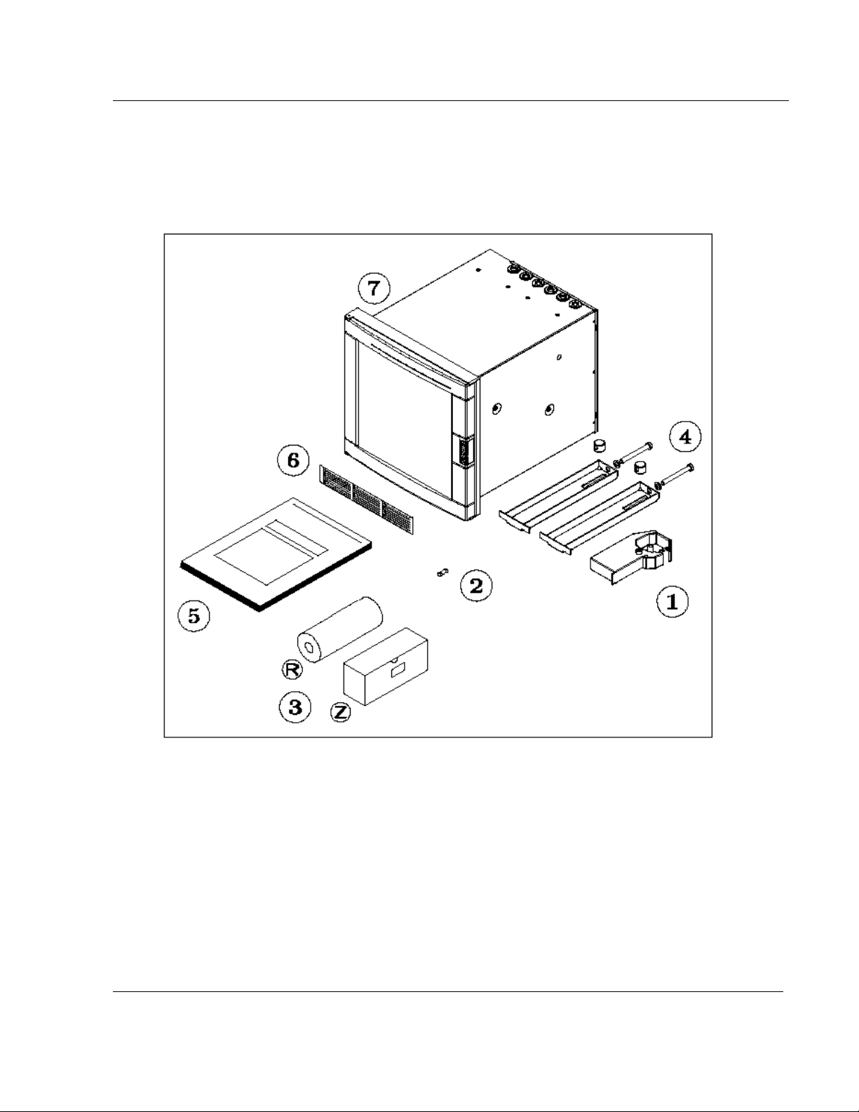
2.2 UNPACKING
Remove the accessories and check them against the figure below.
2. INSTALLATION
1. Ribbon cartridge
2. Fuse (Spare) (Use only 3.15 A T. fuses for
Europe or 3.2 A T. fuses for U.S.)
3. Roll (R) and fanfold (Z) chart
NOTE: In the event that any items are missing, please contact your nearest sales office.
4. Mounting brackets with nuts
5. Product manual or CD
6. Front label
7. Recorder
2-3
Page 18
2. INSTALLATION
2.3 PANEL MOUNTING THE RECORDER
2.3.1 Recommendations
This recorder is designed to operate under specific conditions. If you need more information, refer to the
product specification sheet.
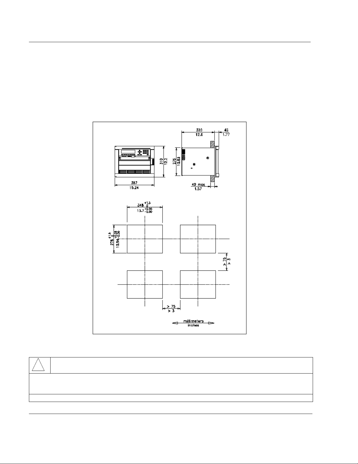
2.3.2 External dimensions and cut-out
Prepare panel cut-out as detailed below:
Note: Maximum panel thickness 40 mm (1.5 '')
CAUTION
!
The maximum temperature inside the cabinet should not exceed the ambient conditions specific for the
recorders. The recorder must be mounted into a panel to limit operator access to the rear terminals.
Failure to comply with these instructions may result in product damage
2-4
Page 19

2.3.3 Installing the recorder
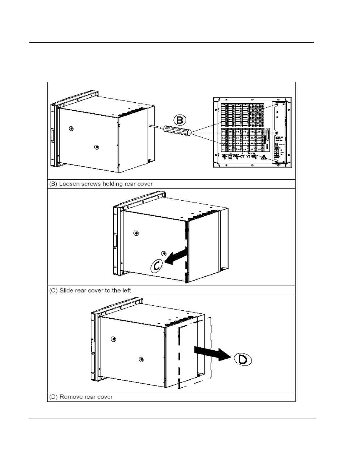
To install the recorder, follow the figures below:
1. Remove rear cover and wire access holes.
2. Insert recorder through the panel cutout
3. Attach mounting brackets to the sides of the recorder
4. Tighten the mounting screws
2. INSTALLATION
2-5
Page 20

2. INSTALLATION
2-6
Page 21

2.4 WIRING THE RECORDER
2.4.1 Recommendations
• All wiring must be in accordance with local electrical codes and should be carried out by
authorized experienced personnel.
• The ground terminal must be connected before any other wiring (and disconnected
last).
• A switch in the main supply is recommended near the equipment.
• If an external fuse is used to protect the electrical circuit to the recorder, the fuse
should match the recorder fuse rating (fuse type) as well as for the fuse holder.
• Sensor wiring should be run as far as possible from power wiring. (motors, contactors,
alarms, etc.)
• To reduce stray pick-up, we recommend the use of a twisted pair sensor wiring.
• EMI effects can be further reduced by the use of shielded cable sensor wiring. The
shield must be connected to the ground terminal.
• The use of spade terminals on all wiring is recommended.
2. INSTALLATION
2-7
Page 22
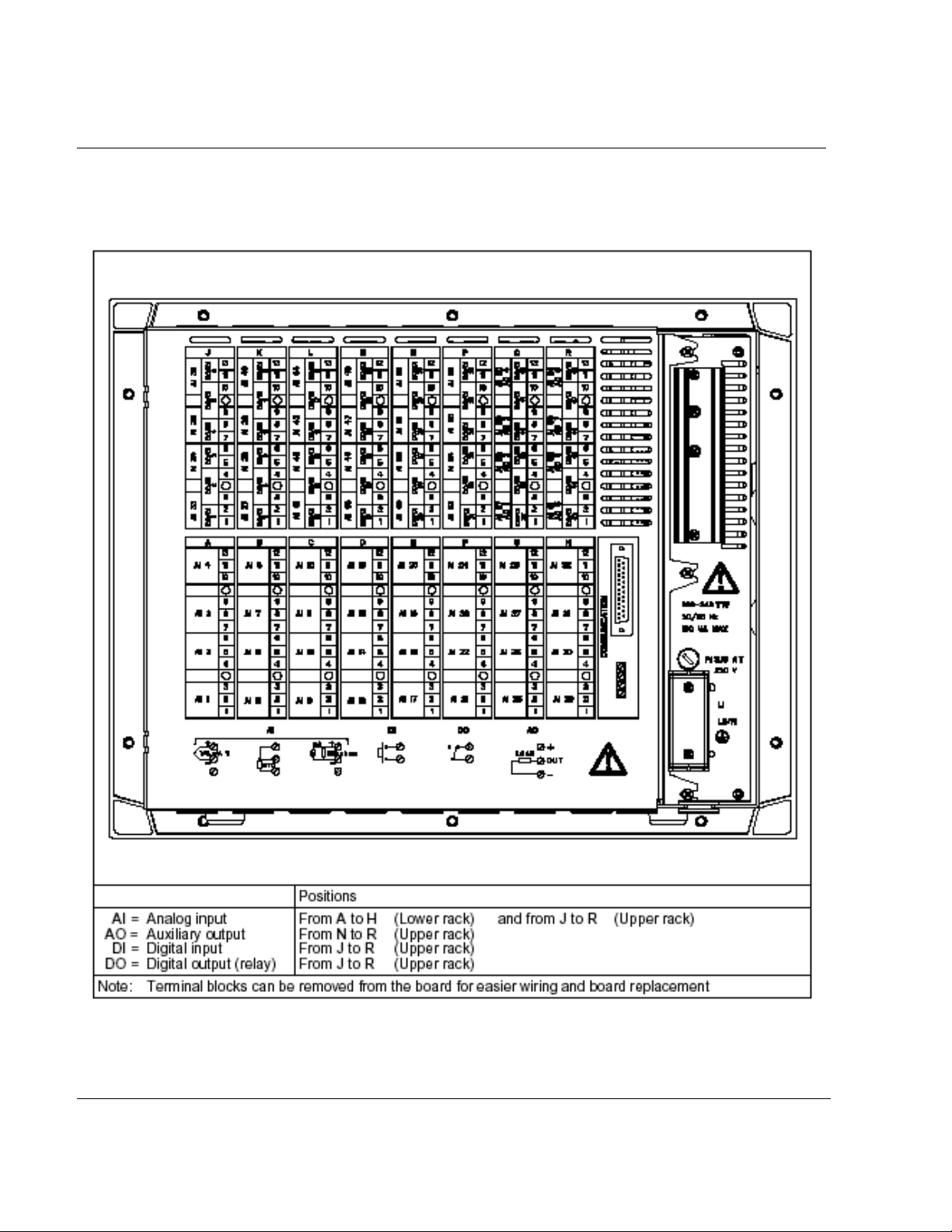
2.5 TERMINAL CONNECTIONS
2. INSTALLATION
2-8
Page 23

2. INSTALLATION
Note: Terminal (A) is only used for RTD. (See diagrams above)
CAUTION
!
Unwired configured channel terminals should be shorted.
Failure to comply with these instructions may result in product damage
2-9
Page 24

2. INSTALLATION
2.5.1 Digital input signals. (DI)
If an optional digital input board is installed, connect the wiring as shown in Figure 2-1.
Slot location X = J to P
Figure 2-1 Digital input signal wiring (DI)
If 2 digital input boards are fitted, repeat the above procedure for the second board.
Note: Use dry contacts, voltage free, designed to switch 5 mA at 5 V.
Up to 36 digital inputs allowed.
2-10
Page 25
2. INSTALLATION
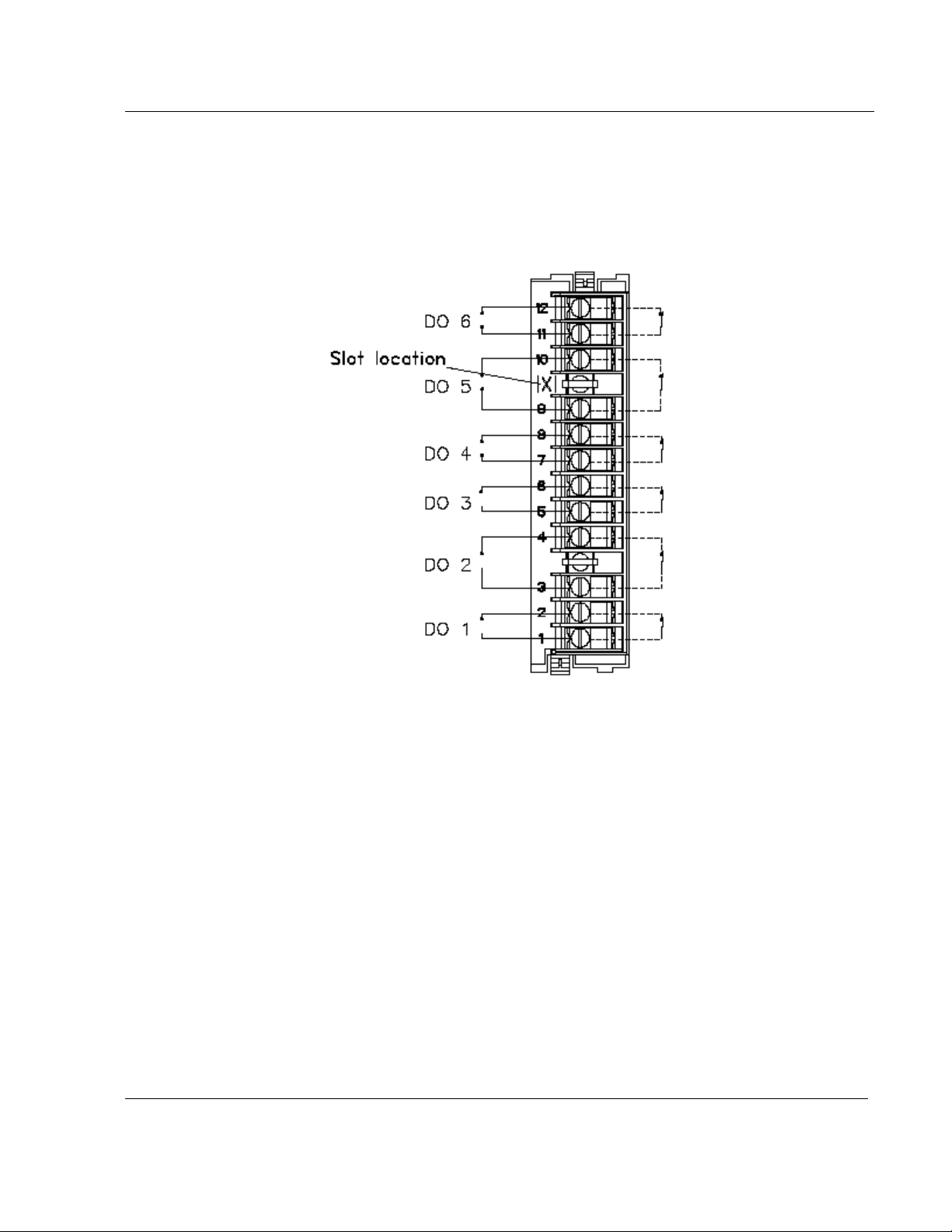
2.5.2 Relay outputs. (DO)
If an optional relay board is installed, connect the wiring as shown in Figure 2-2.
Slot location X = J to P
Figure 2-2 Relay output wiring (DO)
All the relays are factory configured de-energized in alarm. The contacts are factory configured normally
closed by a jumper per output on the alarm relay board.
If you need to change this function for normally opened output:
• Turn off power.
• Remove the rear terminal cover plate and remove the relay board, see page 2-11.
• Move the jumper from the location NC (for normally closed) to the location NO (for normally
opened).
• Up to 36 alarm outputs allowed.
2-11
Page 26
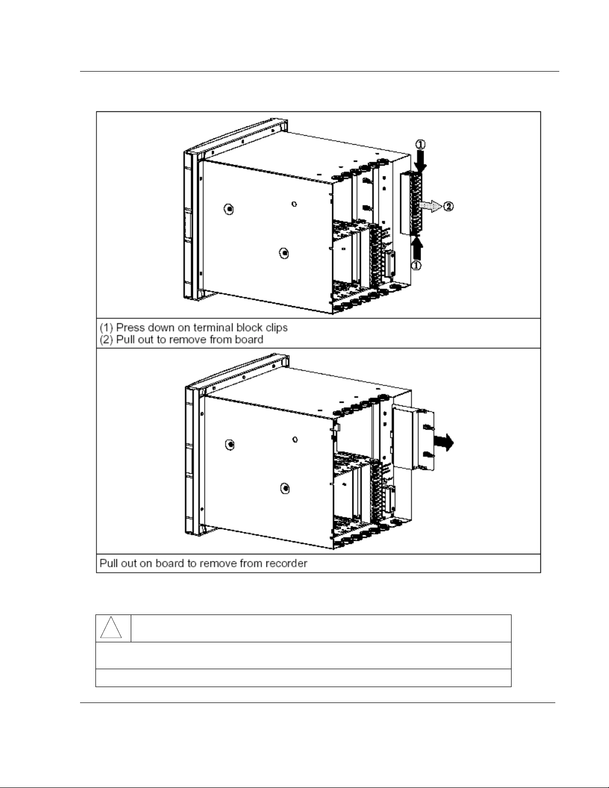
2.5.2.1 Removing the alarm card to change NC to NO contacts
(A) Turn off power.
2. INSTALLATION
2-12
Page 27
2. INSTALLATION
Use ground strap to avoid electrostatic damage to board.
CAUTION
!
Use ground strap to avoid electrostatic damage to board.
Failure to comply with these instructions may result in product damage
2-13
Page 28
2. INSTALLATION
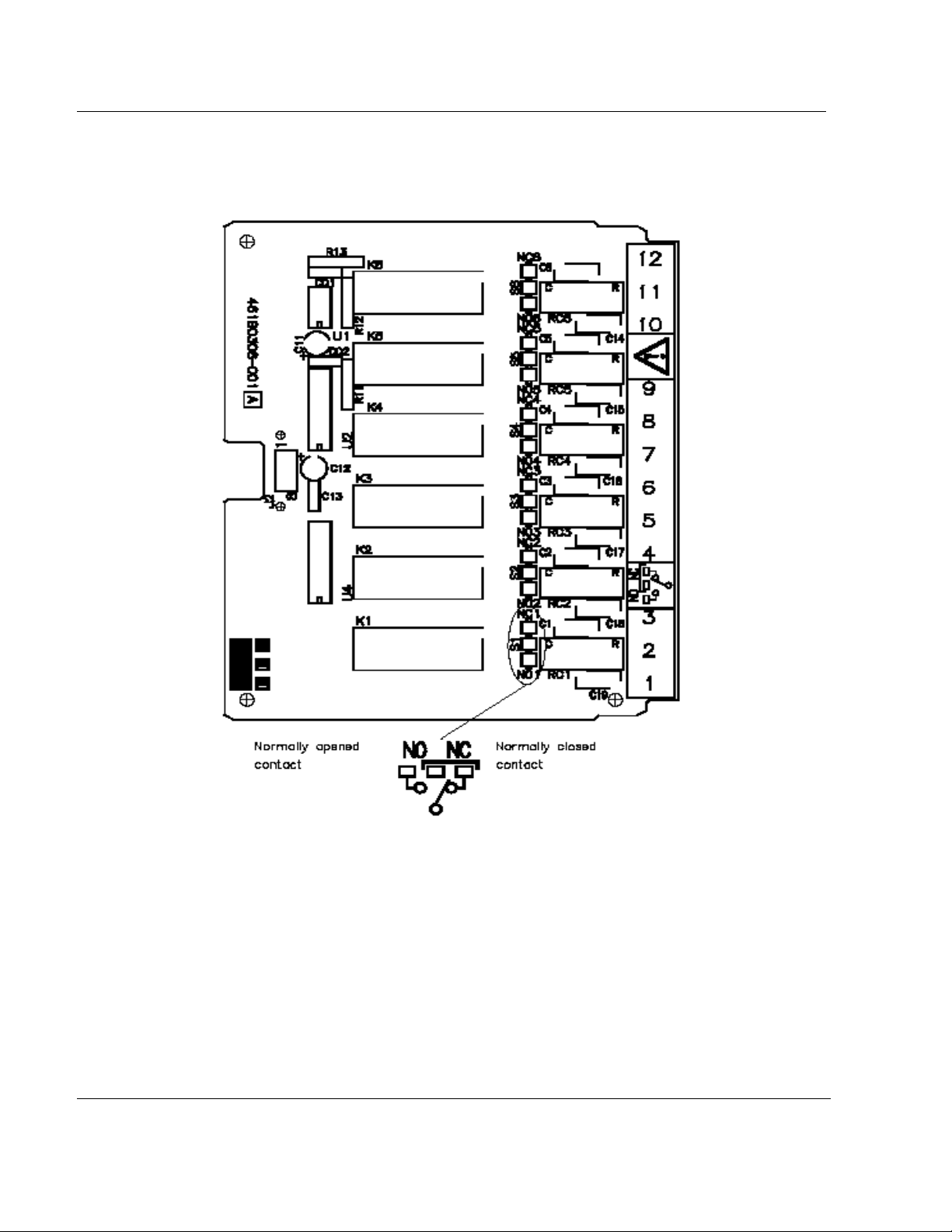
All the relays are factory configured de-energized in alarm. The contacts are factory configured normally
closed by a jumper for each output on the alarm relay board.
If you need to change this function:
• Move the jumper from the location NC (for normally closed) to the location NO (for normally
opened)
2-14
Page 29

2.6 FITTING THE CHART
2. INSTALLATION
2-15
Page 30

2. INSTALLATION
2.6.1 Chart cassette
Open the chart cassette as shown below and install the chart using the figure on the cassette.
1 = First action - Press in on both tabs to release chart cassette
2 = Second action - Pull out on the tabs to remove cassette
2-16
Page 31

2. INSTALLATION
2-17
Page 32

2. INSTALLATION
2-18
Page 33

2. INSTALLATION
2-19
Page 34

2. INSTALLATION
Note: If the recorder is powered, and the message "NO PAPER" is indicated on the display, carefully check
again that the cassette assembly and chart are correctly installed.
NOTICE
Reset the paper length (if configured) after installing the new chart. See section 3.2
"OPERATOR INTERFACE".
Length 35 m (115 ft) or less to provide sufficient warning that the paper is near its end.
2-20
Page 35

2. INSTALLATION
2.6.2 Cleaning the rod and lubricating the carriage bushings
The print carriage bushings are factory lubricated and should not normally require further maintenance.
However, in a dusty environment, you should have to clean the print carriage rod periodically.
Also, whenever the print carriage rod is found sticky or dirty, you have to clean it.
The procedure for cleaning and lubricating is explained below:
1. Power off the recorder.
2. Clean the rod with a dry, lint free cotton cloth.
3. Move the carriage to the center of the rod.
4. Apply a thin ring of grease around the rod, at each side of the carriage (as shown above).
5. Move the carriage from right to left four or five times.
6. Wipe off any excess grease from the rod with a dry, lint free cotton cloth.
CAUTION
!
Never use any solvent to clean the rod.
Please, use only lubricant "Dow Corning white EP grease or equivalent" which may be ordered as
part number: "Lubricant kit 46210096-501".
Failure to comply with these instructions may result in product damage
NOTE:
The color ribbon axis (50 mm long), which keeps maintained the color ribbon, must be cleaned with a dry
cotton cloth each time you replace the color ribbon.
2-21
Page 36

2. INSTALLATION
2.7 INSTALLING THE PRINTING SYSTEM
Before doing it, please remove the chart cassette from the chassis as indicated page 2-15.
The recorder automatically moves the print carriage to the correct position for the installation of the ink
ribbon cartridge by:
CAUTION
!
Do not attempt to install the ribbon cartridge while the chart cassette is in place.
Failure to comply with these instructions may result in product damage
2-22
Page 37

2. INSTALLATION
2-23
Page 38

2. INSTALLATION
2.8 CHECK LIST
Your recorder should now be ready to configure and use. If you are having problems check the
following
1. Have you connected the ground terminal ?
2. Have you connected the sensor(s) correctly? (Wire type, polarity, etc.)
3. Have you tightened all terminal screws?
4. Have you installed the ink ribbon cartridge? (See figures on page 2-22)
5. Have you installed the chart correctly? (See figures on page 2-15)
6. Have you closed the display?
7. Have you fitted the chart cassette in the recorder?
8. Have you replaced the rear cover?
9. Have you switched ON the power switch?
2-24
Page 39

3. OPERATION
TABLE OF CONTENTS
Section Page
3.1 OPERATOR INTERFACE EXPLANATION . . . . . . . . . . . . . . . . . . . . . . . . . . . . . . . 3-2
3.2 OPERATOR INTERFACE
3.3 POWER UP
3.3.1 Power up display sequence
3.4 SELECTING AND INTERPRETING RUN MODE DISPLAY
3.4.1 INTRODUCTION
3.4.2 How to select a display type
3.4.3 How to explain displays in run mode
. . . . . . . . . . . . . . . . . . . . . . . . . . . . . . . . . . . . . . . . . . . . . . . . . . . . . 3-5
3.3.1.1 Display test. . . . . . . . . . . . . . . . . . . . . . . . . . . . . . . . . . . . . . . . . . 3-5
3.3.1.2 Measure initialization . . . . . . . . . . . . . . . . . . . . . . . . . . . . . . . . . . . . . 3-5
3.4.3.1 For a selection either on the upper display and/or on the lower display . . . . . . 3-7
3.4.3.2 Exception: For selections on the 2 displays with the same display type. . . . . . 3-9
3.4.3.3 LOCK displays . . . . . . . . . . . . . . . . . . . . . . . . . . . . . . . . . . . .. . . . . . 3-9
. . . . . . . . . . . . . . . . . . . . . . . . . . . . . . . . . . . . . . . . . . . 3-2
. . . . . . . . . . . . . . . . . . . . . . . . . . . . . . . . . . . . 3-5
. . . . . . . . . . . . . . . . . . . . . . . . . . . . . . . . . . . . . . . . . . . . . 3-6
. . . . . . . . . . . . . . . . . . . . . . . . . . . . . . . . . . . . . 3-6
. . . . . . . . . . . . . . . . . . . . . . . . . . . . . . . . 3-7
. . . . . . . . . . . . . . . . . . . . 3-6
3.5 OPERATOR INITIATED ACTIONS
3.5.1 Hold display . . . . . . . . . . . . . . . . . . . . . . . . . . . . . . . . . . . . . . . . . . . . . . . . . 3-11
3.5.2 Printer action
3.5.3 RESET display
3.5.4 Alarm acknowledgment . . . . . . . . . . . . . . . . . . . . . . . . . . . . . . . . . . . . . . . . . 3-13
3.6 GLOSSARY OF OPERATING DISPLAY MESSAGES
. . . . . . . . . . . . . . . . . . . . . . . . . . . . . . . . . . . . . . . . . . . . . . . . 3-12
. . . . . . . . . . . . . . . . . . . . . . . . . . . . . . . . . . . . . . . . . . . . . . . 3-13
. . . . . . . . . . . . . . . . . . . . . . . . . . . . . . . . . . . . . 3-11
3-1
. . . . . . . . . . . . . . . . . . . . . . . 3-14
Page 40

3. OPERATION
3.1 OPERATOR INTERFACE EXPLANATION
This section describes the various actions which an operator can initiate through the keyboard, and explains
how to interpret the displays in the different modes of operation available.
3.2 OPERATOR INTERFACE
DISPLAY AND KEYPAD: The display gives a clear indication of action prompts by means of two lines of 16
characters and the keypad consists of 23 keys.
• 7 function keys that enable you to start immediate action. See table below.
FUNCTION KEYS
F1 HOLD PRINT RESET ACK DISPLAY F2
Immediate
action key
configurable
To hold the
display on a
current
channel.
Use !and
"keys to
change the
channel.
To choose an
Immediate printing
action.
The choices are:
- Inhibit/Printing
- Reset paper length
- Change speed/ int 2
to speed/ int 1
- Print date & time
- Snap shot trace
- Chart advance
- Change group B to
A
- Change group A+B
to B
- Snap shot logic
- Snap shot math
- Start archive/stop
archive
- Remove PCMCIA
- Math
- Occurrence
- Reset
PCMCIA
To
Acknowledge
all latching
alarm relays
To choose the
display type in
run mode or to
escape
from
configuration
to run mode
NOTE: The function keys are used in run mode and they control the contents of the display and other
functions. In case of a power loss the configuration is unchanged.
• #$!" : THESE KEYS ARE USED FOR PRODUCT CONFIGURATION.
• SET UP: To move to configuration mode or to return from parameter configuration to the sub-
matrix.
• ENTER: To confirm your selected action.
• An ALPHANUMERIC keypad with either capital and small print letters, digits or special characters.
Immediate
action key
configurable
3-2
Page 41

3. OPERATION
The keypad is designed to simplify the way to configure your parameters.
Two kinds of parameters are possible:
1. Parameters in which you only have to enter digits (eg: CHART SPEED) or to enter a letter (COPY
function). Both cases, the keyboard will automatically be configured correctly.
2. Parameters which need every possible ASCII characters defined in the recorder (eg: MESSAGE).
When you confirm the action to enter configuration mode, a triangle in the right hand bottom corner of
your display is lit. It indicates that you are in capital letter mode. Depending on the type of characters
you wish to enter, you will have to press the F2 key. Then it will automatically shift to the next group of
characters (digits, small print letters, special characters, capital letters) indicated on the display by a
triangle. Then you will be able to select the way you wish to write the text.
3-3
Page 42

3. OPERATION
You will find in the table below the different letters associated to each key:
Digits
1 ABC abc
2
3
4
5
6
7
8 VWX vwx
9
0 , -
Capital
letters
DEF def Ä Ö Ü
GHI ghi
JKL jkl
MNO mno
PQR pqr
STU stu
YZ yz
Space Space Space
Note: The selection can also be made with the ! and " keys in the same way as for parameters
containing a list of choices.
Small
print
letters
Special characters
Ω
°
A
Ampere
V
Volt
C
Celsius F Fahrenheit
ñ Ñ
/
*
- +
±
[ ] ( ) { }
. , ; : ! ?
=
≠
" _ # $
m
milli
\
K
kilo
√ ∑ φ
< >
µ
micro
M
mega
≤ ≥
% &
n
nano
∫ ˆ
Å
.
G
giga
3-4
Page 43

3. OPERATION
3.3 POWER UP
WARNING
Before powering up, check your recorder is correctly installed. See section 2, "INSTALLATION".
!
Failure to comply with these instructions could result in death or serious injury
3.3.1 Power up display sequence
After powering up, check the messages appear on the displays in the following order:
3.3.1.1 Display test
Check that all dots for each character, commas and triangle marks are lit.
Upper display shows:
INITIALIZATION
If the communication board is present,
Upper display shows:
INITIALIZATION
Lower display shows:
COMMUNICATION
3.3.1.2 Measure initialization
Upper display shows:
INITIALIZATION
Lower display shows:
MEASURE
During a few seconds, the recorder reads and analyzes every inputs. After these operations of initialization,
input values appear on the 2 displays in run mode.
3-5
Page 44

3. OPERATION
3.4 SELECTING AND INTERPRETING RUN MODE DISPLAY
3.4.1 INTRODUCTION
The recorder allows you to choose between a lot of display types when in the normal scanning mode. At the
end of the power display sequence (see section 3-5, "POWER UP"), the display will be in the scanning
mode, in the display type you have selected in the configuration matrix of the display (Parameters: DISPLAY
HI, DISPLAY LO).
To select another display type (for the lower and/or the upper display), use the DISPLAY key (See next
section 3.4.2 ) or use the configuration mode.
3.4.2 How to select a display type
• The immediate action keys are not available if you are in configuration mode.
• The selection of the DISPLAY key is lost at the power off.
• Press the DISPLAY key. Then you can read:
DISPLAY HI
The upper display is flashing.
DISPLAY LO
• The ! and " keys allow you to select the desired display. Confirm your choice by pressing
the ENTER key.
According to your choice, you may obtain:
DISPLAY HI
ANALOG INPUTS
or
Electrical input signal
DISPLAY LO
ANALOG INPUTS
• The ! and " keys allow you to select the desired display mode on the lower display.
Electrical input signal
3-6
Page 45

3. OPERATION
NOTICE
In particular cases, you may be allowed to select a display type or a parameter only in the upper
display. See section 3.4.3.3, "LOCK displays".
3.4.3 How to explain displays in run mode
3.4.3.1 For a selection either on the upper display and/or on the lower display
ANALOG INPUTS
•
Analog input numbers, measured values and sensor engineering units will be displayed.
AN 0 1 1 2 4 . 2 o C
AN = mnemonic for analog input
• Two printed channels on the same display
0 1 2 4 . 2 & 2 4 . 3
01: channel number
24.2: channel value of channel 1
24.3: channel value of channel 2
Note that the second channel number is incremented by 1 from the first channel number.
If, for example, the first channel is not configured, no value will be displayed, e.g.
0 3 & 2 4 7 . 2
• COMMUNICATION CHANNELS
COM 0 1 2 5 4 . 9
• COM = mnemonic for communication channel
3-7
Page 46

3. OPERATION
• ALARMS
For each operated alarm, alarm number, alarm state, relay number, relay state, channel type and channel
number will be displayed.
AL 0 4 " - RL 0 6 _ - AN 1 1
AL 0 4 "- RL 0 6 _ - MA 1 2
AL 0 4 "- RL 0 6 _ - CO 0 1
" active _ inactive . = missing
AL = mnemonic for alarm
RL = mnemonic for relay
AN = mnemonic for analog input
MA = mnemonic for maths results
CO = mnemonic for comm. Channels
• SPEED IN USE
In the trend mode, speed number, value and unit will be displayed.
SP 1 1 5 0mm / h
SP 1 or SP 2 = mnemonic for speed 1 or speed 2
In tabular mode, interval name, time and unit will be displayed.
INT 1 1 0 m i n
INT1 or INT2 = mnemonic for interval 1 or interval 2
• DATE AND TIME
Day, month, year, hour "h" and minutes will be displayed.
2 5 FEB 9 6 1 1 h 1 3
3-8
Page 47

3. OPERATION
3.4.3.2 Exception: For selections on the 2 displays with the same display type
In this case the upper display shows odd numbers and the lower one shows even numbers.
For example:
AN 0 1 1 2 4 . 2 oC
AN 0 2 5 4 4 . 7 oC
If a channel is not configured or does not exist, when previous or next channel is correct, then display mode
and channel number are only displayed. See the examples below:
Only channel 01 is not correct:
AN 0 1
AN 02 1 4 . 1 oC
Only channel 06 is not correct:
AN 0 5 7 4 . 3 oC
AN 0 6
3.4.3.3 LOCK displays
In this case you are allowed to select a display mode only in the upper display.
• MATHS RESULTS
MA 2 0 TAG NAME
1 . 3 2 E + 1 2 UNITS
The upper display shows the tag name
The lower display shows the value and unit of maths results.
To display maths results, the maths option is required
3-9
Page 48

3. OPERATION
• TAG NAME AND TRACE
LOCK displays mean that the 2 displays are necessary to keep information together.
TAG NAME
0 1 2 5 8 . 1 UNITS _
The upper display shows the channel name.
The lower display shows number, value, unit and indicator of the alarm.
If the channel is in alarm status and if the alarm parameter (See EVENTS matrix, ONE ALARM ON
parameter) is not valid, then the "A" indicator appears on the last digit of the display. On the contrary units
are displayed and the alarm number is displayed just after, as follows
If ALARM and EVENTS are ON:
TAG NAME AL 1 2
0 1 2 5 8 . 1 U N I T S "
• TRACES IN ALARM
The upper display shows the name of the display type "TRACE IN ALxx-yy" and the display interval of the
lower display.
TRACE IN AL x x - y y
# # # # # # # # # # # # # # # #
The lower display shows the trace status of alarm.
"xx" - "yy" takes values from "01 to 16" or "17 to 24".
# = you may have:
" active _ inactive . = missing
3-10
Page 49

• LOGICAL INPUT STATUS
The 2 displays are necessary.
3. OPERATION
DI XX - - - > Y Y
# # # # # # # # # # # # # # # #
The upper display shows the name of the display type "DI" and the display interval of the lower display.
The lower display shows the digital input status.
"xx" - "yy" takes values from "01 to 16" or "17 to 24".
# = you may have:
" contact closed _ contact opened . = missing
3.5 OPERATOR INITIATED ACTIONS
3.5.1 Hold display
The HOLD key allows you to stop the scanning action while displaying current value of the selected channel
(upper display only).
The selection of the HOLD key is lost at the power off.
In case of locked displays, see section 3.4.3.3, "LOCK displays".
Then press HOLD key, the HOLD message appears on the upper display during a few seconds. And the
current value is displayed with two lit triangle marks, as shown below:
HOLD
0 1 2 4 5 . 5 UNITS
" "
These two triangle marks allow you to scan the other channels.
NOTE: Some display types do not allow you to use the HOLD key, like DATE/TIME, SPEED.
3-11
Page 50

3.5.2 Printer action
The PRINT key allows you to choose between various actions.
Press PRINT key and the upper display shows during a few seconds:
BASIC ACTION
and just after:
3. OPERATION
PRINT MENU
INHIBIT PRINTING
or
RESET PAPER LENG
SPEED / INT 2
or
SPEED / INT 1
PRINT DATE & TIME
SNAP SHOT TRACE
CHART ADVANCE
The chart advances as long as the
ENTER key is pressed.
CHG GROUP B
CHG GROUP A + B
SNAP SHOT LOGIC
or
CHG GROUP A
or
CHG GROUP B
3-12
Page 51

3. OPERATION
SNAP SHOT MATH
START ARCHIVE STOP ARCHIVE
or
REMOVE PCMCIA
Only when PCMCIA option is installed.
Press ENTER and use ! or " to choose the display type.
3.5.3 RESET display
Only when MATH OPTION is configured.
RESET MATH #
RESET ALL MATHS
RESET OCCURRENCE
RESET ALL OCCUR
RESET PCMCIA
Only when PCMCIA option is installed.
3.5.4 Alarm acknowledgment
Pressing ACK key is only allowed for alarms you have configured in acknowledgment mode.
This acknowledgment is only available
• f the lower display shows alternately:
REQUEST ACK NOW
and the display type,
- if the ACK key is active.
(See ACK KEY parameter in the MMI sub-matrix)
3-13
Page 52

3.6 GLOSSARY OF OPERATING DISPLAY MESSAGES
• ENTERING IN THE IMMEDIATE ACTION MODE
3. OPERATION
BASIC ACTION
• DISPLAY CHOICE
DISPLAY HI
DISPLAY LO
• DISPLAY MODE CHOICE
ANALOG INPUTS
2 PVS TRACE
MATH RESULTS
Electrical input signal
Process value in engineering unit
Only when MATH OPTION is configured.
COMM RESULTS
Only when COMM OPTION is configured.
ALARM STATUS
SPEED IN USE
3-14
Page 53

3. OPERATION
DATE & TIME
TRACE & TAG
TRACE IN ALARM
LOGIC STATES
• ACK MESSAGES
REQUEST ACKNOW
ACKNOWLEDGMENT
• INFORMATION MESSAGES
NO PAPER
END PAPER
BATTERY FAIL
ONE ALARM ON
BURNOUT
PRT INHIBIT
3-15
Page 54

OVER FLOW SPEED
3. OPERATION
SHED TIME
PCMCIA FULL
PCMCIA BAD
PCMCIA NOT INIT
PCMCIA PENDING
REMOVE PCMCIA
Only when COMM option is configured.
Only when PCMCIA option is configured.
• Diagnostic Messages
BAD CARRIAGE DISP
BAD REFERENCE
BAD EEPROM BACKPLANE
3-16
Page 55

4. CONFIGURATION
TABLE OF CONTENTS
Section Page
4.1 INTRODUCTION . . . . . . . . . . . . . . . . . . . . . . . . . . . . . . . . . . . . . . . . . . . . . . . . . . 4-2
4.2 PARAMETERS LIST . . . . . . . . . . . . . . . . . . . . . . . . . . . . . . . . . . . . . . . . . . . . . . . 4-4
4.3 PRINCIPLE OF CONFIGURATION . . . . . . . . . . . . . . . . . . . . . . . . . . . . . . . . . . . . 4-5
4.4 COPY CONFIGURATION . . . . . . . . . . . . . . . . . . . . . . . . . . . . . . . . . . . . . . . . . . . 4-105
4.4.1 Introduction
4.4.2 Configuration
4.4.3 WARNING
4.5 PRINT CONFIGURATION . . . . . . . . . . . . . . . . . . . . . . . . . . . . . . . . . . . . . . . . . . . 4-110
4.5.1 Introduction
4.5.2 Configuration
4.5.3 Information about printing
4.5.4 WARNING
4.6 CONFIGURABLE AND PRINTABLE CHARACTERS . . . . . . . . . . . . . . . . . . . . . . . . 4-116
INDEX . . . . . . . . . . . . . . . . . . . . . . . . . . . . . . . . . . . . . . . . . . . . . . . . . . . . . . . . . . 4-117
. . . . . . . . . . . . . . . . . . . . . . . . . . . . . . . . . . . . . . . . . . . . . . . . . 4-105
. . . . . . . . . . . . . . . . . . . . . . . . . . . . . . . . . . . . . . . . . . . . . . . . 4-105
. . . . . . . . . . . . . . . . . . . . . . . . . . . . . . . . . . . . . . . . . . . . . . . . . . 4-109
. . . . . . . . . . . . . . . . . . . . . . . . . . . . . . . . . . . . . . . . . . . . . . . . . 4-110
. . . . . . . . . . . . . . . . . . . . . . . . . . . . . . . . . . . . . . . . . . . . . . . . 4-111
. . . . . . . . . . . . . . . . . . . . . . . . . . . . . . . . . . . . . . . 4-115
. . . . . . . . . . . . . . . . . . . . . . . . . . . . . . . . . . . . . . . . . . . . . . . . . . 4-115
4-1
Page 56

4. CONFIGURATION
4.1 INTRODUCTION
The recorder can be configured - using the front keyboard or by using the PC configurator and L.P.C.S.
When using the keyboard there are two possible levels of password that can be configured. Password 1
provides limited configuration access as shown on the configuration sheet (See page 4-92). Password 2
provides full configuration of all parameters (See page 4-93).
Page 4-1 provides a key to each explanation for the individual parameters.
To begin configuration you only need to press SET UP. The recorder will indicate "CONFIGURATION", "
ACCESS" and wait for a password to be entered if one has been programmed. If no password has been
programmed the recorder will display the "READ/WRITE", "ANALOG INPUT" position (see programming
matrix). You can now use the LEFT or RIGHT side arrows to select the sub-matrix you want to configure
(i.e. ANALOG INPUT, CHART, ALARM etc.) or the UP or DOWN arrows to select the READ/WRITE,
COPY, PRINT CONF or SERVICE matrices and then use the LEFT or RIGHT arrow to enter into one of
these sub-matrices. When you have selected the sub-matrix that you want to configure you only need to
press ENTER to begin configuration of this sub-matrix.
Each sub-matrix such as ANALOG INPUT has a number of parameters associated with it that need to be
configured in order to set up that parameter and channel. Each parameter needs to be configured for each
input. To exit from the configuration mode press DISPLAY or SET UP keys.
4-2
Page 57

SUB-MATRIX PARAMETER CLASSIFICATION
NAME OF THE
FUNCTION
DEFINITION:
HOW TO MODIFY IT:
POSSIBLE VALUES:
SEE ALSO:
EXAMPLE:
NOTE:
NOTICE
4. CONFIGURATION
IMPORTANCE OF THE PARAMETER
NAME OF THE
PARAMETER
EXPLAIN THE ROLE OF THE PARAMETER
BY SELECTING OR ENTERING A NEW VALUE I.E. USING
! # KEYS
THE
LIST OF POSSIBLE VALUES OR LIMITS
The configuration of parameters with the classification “!!“ stops the
acquisition as well as the operation of alarm supervision.
Leaving the configuration mode resets the memory buffer and the alarm status
is defined again, and the chart speed changes back to the configured value.
Occurrence value is reset.
! CAN BE CHANGED IN RUN MODE
!! STOP OF ACQUISITIONS
! WITH PASSWORD 1 OR 2
!! ONLY WITH PASSWORD 2
4-3
Page 58

4. CONFIGURATION
4.2 PARAMETERS LIST
$ ANALOG INPUT page 4-6
$ CHART page 4-20
$ ALARM page 4-31
$ DIGITAL page 4-47
$ MESSAGES page 4-57
$ PRINTER page 4-60
$ CHART DOC page 4-69
$ MMI page 4-77
$ EVENTS page 4-84
$ MISCELLANEOUS page 4-88
$ PERIODIC REPORT page 4-96
$ CURRENT 4/20 mA page 4-102
4-4
Page 59

4.3 PRINCIPLE OF CONFIGURATION
4. CONFIGURATION
4-5
Page 60

4. CONFIGURATION
4-6
Page 61

4. CONFIGURATION
SUB - MATRIX ANALOG INPUT
Configuration of analog input parameters
PARAMETERS SENSOR page 4-7
RANGE page 4-12
EXT COMP page 4-13
FILTER page 4-14
LOW VALUE page 4-15
HIGH VALUE page 4-15
STD MATH page 4-16
DIFF WITH page 4-17
BURNOUT page 4-18
LOW ADJUST page 4-19
HIGH ADJUST page 4-19
4-7
Page 62

SUB-MATRIX PARAMETER CLASSIFICATION
ANALOG INPUT
DEFINITION:
HOW TO MODIFY IT:
POSSIBLE VALUES:
SEE ALSO:
NOTE:
4. CONFIGURATION
SENSOR
Basic: sensor type used on each channel.
Select a new sensor. Press ENTER. With keys # ! select the right sensor type
and press ENTER
T/C INT COMP: The sensor is a directly connected thermocouple and the cold junction
compensation of the recorder is used.
T/C EXT COMP: Thermocouple sensor is directly connected to a remote temperature
compensation box *.
* See parameter EXT COMP to configure temperature or analog channels (see page 4-
14) used to measure the external cold junction.
RTD: Sensor is a directly connected RTD or variable resistance device.
TR NL 0-5V: Sensor is a temperature transmitter signal range of 0-5V which is not
linear with temperature.
TR NL 1-5V: Sensor is a temperature transmitter signal range of 1-5V which is not
linear with temperature.
TR NL 0-20mA : Sensor is a temperature transmitter signal range of 0-20mA which is
not linear with temperature.
TR NL 4-20mA: Sensor is a temperature transmitter signal range of 4-20mA which is
not linear with temperature.
LINEAR: Sensor is a transmitter output which is linear with process variable.
SPECIAL: Special sensor connected. Must be specified by special order,
or created using PC application software.
NO ENTRY: No sensor connected or unused input.
RANGE to select the required input range.
Changing the sensor type will automatically change RANGE, LOW
VALUE, HIGH VALUE into predefined values.
Which is dependent on:
1) The type of analog input board installed (linear or universal)
2) If the input type is a directly connected temperature sensor.
The access to all sensors is possible only with an universal input board.
T/C INT COMP and RTD sensors are not accessible with a linear input
board.
!! !!
4-8
Page 63

SUB-MATRIX PARAMETER CLASSIFICATION
ANALOG INPUT
DEFINITION:
HOW TO MODIFY IT:
POSSIBLE VALUES:
4. CONFIGURATION
RANGE
DISPLAY ACTUATION RANGE
For directly connected temperature sensors and non-linear temperature
transmitters, the actuation selection defines the linearization routine used
to produce a linear chart scale. For linear transmitters, the selection simply
defines the transmitter's range/span.
The choice of actuation offered by the recorder during configuration will
depend upon sensor selected. The ranges allowed will depend on whether
you have selected Thermocouple, Linear or Non Linear or RTD.
Select a new actuation using the # or !arrows and press ENTER
Depends on the type of sensor connected. Possible selections are listed
below.
!! !!
4-9
Page 64

4. CONFIGURATION
AVAILABLE RANGES
LINEAR
DISPLAY
RANGE
DISPLAY
RANGE
mV: mV:
0/10 mV 0, 10 mV -50/150 C
-10/10 mV -10, 0, 10 mV -58/302 F
0/ 20 mV 0, 20 mV 0/100 C
-20/20 mV -20, 0, 20 mV 32/212 F
0/50 mV 0, 50 mV 0/200 C
-50/50 mV -50, 0, 50 mV 32/392 F
10/50 mV 10, 50 mV 0/400 C
0/100 mV 0, 100 mV 32/752 F
-100//100 mV -100, 0, 100 mV -200/800 C
0/500 mV 0, 500 mV -328/1472 F
-500/500 mV -500, 0, 500 mV
Volt: Volt: 320 C
0/1 V 0, 1 V 608 F
-1/1 V -1, 0, 1 V
0/2 V 0, 2 V Ni 508 ohms: Ni 508 ohms:
-2/2 V -2, 0, 2 V 150 C
0/5 V 0, 5 V 302 F
-5/5 V -5, 0, 5 V
1/5 V 1, 5 V Cu 10 ohms: Cu 10 ohms:
0/10 V 0, 10 V 250 C
-10/10 V -10, 0, 10 V 482 F
Pt 100 Ω at 0 ° C Pt 100 Ω at 0 ° C:
-50, 0, 150°C
-58, 0, 302
0, 100°C**
32, 212°F**
0, 200°C
32, 392°F
0, 400°C
32, 752°F
-200, 0, 800°C
-328, 0, 1472°F
°F
Ni 50 ohms: Ni 50 ohms:
-80, 0, 320°C
-112, 0, 608°F
-80, 0, 150°C
-112, 0, 302°F
-20, 0, 250°C***
-4, 0, 482°F***
mA: mA: Ohms: Ohms:
0/20 mA 0, 20 mA*
4/20 mA 4, 20 mA*
0/200 Ω 0, 200 Ω
0/2000 Ω 0, 2000 Ω
* The mA inputs have to be connected on a 250 Ω input resistor across the input terminals.
** Accuracy: 0.25 %
*** Accuracy: 0.5 %
RTD / OHMS
JIS: JIS:
-50/150 C
-58/302 F
0/100 C
32/212 F
0/200 C
32/392 F
0/400 C
32/752 F
-200/500 C
-328/932 F
DISPLAY
RANGE
-50, 0, 150°C
-58, 0, 302°F
0, 100°C**
32, 212°F**
0, 200°C
32, 392°F
0, 400°C
32, 752°F
-200, 0, 500°C
-328, 0, 932°F
4-10
Page 65

4. CONFIGURATION
AVAILABLE RANGES (continued)
THERMOCOUPLES
DISPLAY RANGE DISPLAY RANGE DISPLAY RANGE
J: J: S: S: U: U:
-50/150 C
-50/150 C
-58/302 F
0/400 C
32/752 F
-200/870 C
-328/1598 F
0/400 C
L: L: 32/752 F
-50/150 C
-58/302 F
0/400 C
32/2552 F
-200/870 C
-328/1598 F
0, 1400 C
K: K: T: T: 32/2552 F 32, 2552 oF
0/400 C
32/752 F
0/800 C
32/1472 F
0/1200 C
32/2192 F
-200/400 C
-200/1370 C
-328/2498 F
PR20-40: PR20-40:
R: R:
-20/1760 C
-4/3200 F
B: B:
40/1820 C 400, 1820
104/3308 F 752, 3308oF
-50, 0, 150°C
-50, 0, 150°C
-58, 0, 302°F
0, 400°C
32, 752°F
-200, 0, 870°C
-328, 0, 1598°F
-50, 0, 150°C
-58, 0, 302°F
0, 400°C
32, 2552°F
-200, 0, 870°C
-328, 0, 1598°F
0, 400°C
32, 752°F 0, 800°C
32, 1472°F
0, 1200°C
32, 2192°F
-200, 0, 1370°C
-328, 0, 2498°F
-20, 0, 1760°C
-4, 0, 3200°F
0/1600 C
0/1600 C
32/2912 F
-20/1760 C
-4/3200 F
50/150 C
N: N: 122/302 F
0/800 C
32/1472 F
0/1200 C
32/752 F
-200/1300 C
-328/2372 F
-50/150 C
58/302 F
0/150 C
32/302 F
50/150 C
122/302 F
-328/752 F
PR20 1800C
PR20 3272 F
0, 1600°C
0, 1600°C
32, 2912°F
-20, 0, 1760°C
-4, 0, 3200°F
0, 400°C
32, 752°F
0, 800°C
32, 1472°F
0/1200°C
32, 752°F
-200, 0,1300°C
-328, 0, 2372°F
-50, 0, 150°C
-58, 0, 302°F
0, 150°C
32, 302°F
50, 150°C
122, 302°F
-200, 0, 400°C
-328, 0, 752°F
50/150 C
-50/150 C
-58/302 F
0/150 C
32/302 F
-200/400 C
-328/752 F
NiMo: NiMo:
0/1400 C
32/2192 F
Moco: Moco:
Reference
W-W26: W-W26: Range
-20/2320 C
-4/4208 F
W5-W26: W5-W26:
-20/2320 C
-4/4208 F
50, 0, 150°C
-50, 0, 150°C
-58, 0, 302°F
0, 150°C
32, 302°F
50, 150°C
122, 302°F
-200, 0, 400°C
-328, 0, 752°F
0, 1400°C
32, 2192°F
0, 1400°C
-20, 0, 2320°C 500, 2100°C
-4, 0, 4208 °F 932, 3812 °F
-20, 0, 2320°C 0, 1800°C
-4, 0, 4208°F 32, 3272°F
0, 1800°C 600, 1800°C
32, 3272°F 1110, 3300°F
o
C
400, 1820 °C
752, 3308 °F
4-11
Page 66

SUB-MATRIX PARAMETER CLASSIFICATION
ANALOG INPUT
NOTE:
NOTICE
4. CONFIGURATION
RANGE
For non-linear signals TR NL 0 - 5 V, 1 - 5 V, 0 - 20 mA, 4 - 20 mA, 1 to
5 VDC or 4 to 20 mA or 0 to 5 VDC or 0 to 20 mA, the transmitter range
must be identical to the range shown in the previous tables.
F is used for
°Fahrenheit ; C is used for °Celsius.
!! !!
4-12
Page 67

4. CONFIGURATION
SUB-MATRIX PARAMETER CLASSIFICATION
ANALOG INPUT
DEFINITION:
EXT COMP
The thermocouple sensor is directly connected to a remote temperature
compensation box. Then the connections are made with copper
lead wires. Two types of wiring are possible:
1) At a fixed temperature compensation box with temperature
configurable from 0 up to 80
2) On variable temperature compensation box. We use 1 channel to
measure the temperature of the box.
1) Fixed temperature compensation box
o
C (32 to 176oF).
!! !!
HOW TO MODIFY IT:
NOTICE
2) Variable temperature compensation box
1) Fixed Temperature: Enter a new temperature value in engineering
unit. Choose between VALUE 0 and 80.
2) Variable Temperature: Select the channel used to measure the
temperature of the box.
This parameter is just taken into account if the corresponding channel is
configured with T/C EXT COMP. For T/C INT COMP, RTD and LINEAR, this
parameter has no effect whatever the entered value.
4-13
Page 68

SUB-MATRIX PARAMETER CLASSIFICATION
ANALOG INPUT
DEFINITION:
HOW TO MODIFY IT:
POSSIBLE VALUES:
4. CONFIGURATION
FILTER
You may wish to apply a filter to noisy signals. However if pulses, square
waves or other rapidly changing inputs are to be displayed and recorded
without damping, choose 0 filter value.
Enter a numeric value.
0-99 seconds
0 = No filter
10 = 10 seconds
!! !
NOTICE
All the alarms or maths functions configured on a filtered analog input are
affected by the filter delay. Be mindful with the filter action for the channels on
which a "rate of change" alarm is configured: the filter can suppress the alarm
action.
4-14
Page 69

4. CONFIGURATION
SUB-MATRIX PARAMETER CLASSIFICATION
ANALOG INPUT
DEFINITION:
HOW TO MODIFY IT:
POSSIBLE VALUES:
NOTICE
NOTICE
LOW VALUE
Engineering value corresponding to low limit of the selected input
actuation range.
Enter a numeric value.
Up to 4 digits plus optional sign.
[-9999 ... 9999]
Modification is not allowed for any directly connected temperature sensors, as
this would adversely affect the linearization.
Modification is only possible when the sensor is:
- LINEAR or SPECIAL
- RTD and the range is 0, 200 Ohms or 0, 2000 Ohms
For linear and non-linear transmitters choose the value in engineering
units, which corresponds to the low range limit of the transmitter.
SUB-MATRIX PARAMETER CLASSIFICATION
ANALOG INPUT
DEFINITION:
HOW TO MODIFY IT:
POSSIBLE VALUES:
NOTICE
NOTICE
HIGH VALUE
Engineering value corresponding to high limit of the selected input actuation
range.
Enter a numeric value.
Up to 4 digits plus optional sign.
[-9999 ... 9999]
Modification is not allowed for any directly connected temperature sensors, as
this would adversely affect the linearization.
Modification is only possible when the sensor is:
- LINEAR or SPECIAL
- RTD and the range is 0, 200 Ohms or 0, 2000 Ohms
For linear and non-linear transmitters choose the value in engineering
units, which corresponds to the low range limit of the transmitter.
!! !
!! !
4-15
Page 70

SUB-MATRIX PARAMETER CLASSIFICATION
ANALOG INPUT
DEFINITION:
HOW TO MODIFY IT:
POSSIBLE CHOICES:
SEE ALSO:
NOTE:
4. CONFIGURATION
STD MATH
2 mathematical functions are included as standard in the recorder.
These functions apply only to analog inputs.
Select the maths function.
NO OPT MATH: No maths function configured.
SQUARE ROOT: Square root applies to analog input.
CHANNEL DIFF: Difference between the current analog input and the one
configured in "DIFF WITH".
DIFF WITH in this sub-matrix for CHANNEL DIFF.
1) For SQUARE ROOT the formula is:
!! !!
Smin = min. sensor input value
Smax = max. sensor input value
S = current sensor input value
Available for linear inputs
2) For CHANNEL DIFF, the formula is:
PV = PV
A and B are any analog input.
A - PVB
4-16
Page 71

SUB-MATRIX PARAMETER CLASSIFICATION
ANALOG INPUT
DEFINITION:
HOW TO MODIFY IT:
POSSIBLE CHOICES:
NOTE:
4. CONFIGURATION
DIFF WITH
Second channel used when STD MATH = CHANNEL DIFF
Select a new value.
ANALOG # i (i = 1 ... 64)
NONE
The software will only allow selection of pre-configured input.
For the difference between 2 channels, it is recommended to take
first the highest channel reference and subtract from the other channel.
Example:
You want to make a difference between channels 7 and 12:
make ch12 minus ch7.
!! !!
4-17
Page 72

SUB-MATRIX PARAMETER CLASSIFICATION
ANALOG INPUT
DEFINITION:
HOW TO MODIFY IT:
POSSIBLE CHOICES:
NOTE:
!
CAUTION
Failure to comply with these instructions may result in product damage
4. CONFIGURATION
BURNOUT
Allows you to define the safety backup position to activate alarms (if
configured) in case of sensor burnout. The trace can go either on the right
(high) or on the left (low).
Select new text.
NO BURNOUT: No burnout.
B OUT LOW: Burnout configured low scale. Display shows [-9999]
B OUT HIGH: Burnout configured high scale. Display shows [9999]
FIX LOW: Value fixed low. (mA) Not configurable
FIX HIGH: Value fixed high. (RTD/OHMS) Not configurable
FIX NONE: Undefined value. Not configurable (Linear sensors)
0 to 10 V / - 5 to 5 V / -1 to 1 V / -500 to 500 mV
- For some sensors (mA, RTD, Volts), burnout is not configurable but fixed
and display will show FIX LOW, FIX HIGH or FIX NONE.
The value will be out of range (low, high or undefined). The "BURNOUT" event
is only activated with the B OUT LOW or B OUT HIGH configuration.
- For RTD/OHMS sensors, a third wire burnout cannot be detected: the output
value will be undefined.
For configurable burnout, be aware that a current pulse of 0.125 mA will
occur regularly as part of the burnout detection and may disturb other
devices connected to the same sensor. For an application with another
controller connected on the same current loop, please remove the
burnout detection on your recorder.
!! !!
4-18
Page 73

SUB-MATRIX PARAMETER CLASSIFICATION
ANALOG INPUT
DEFINITION:
HOW TO MODIFY IT:
POSSIBLE CHOICES:
EXAMPLE:
4. CONFIGURATION
LOW ADJUST
HIGH ADJUST
Zero adjust and span adjust are values used to calibrate a temperature loop.
Otherwise choose 0 Value = Factory Calibration
Adjustments are made directly in Engineering unit to the input range.
(ex.: 5 = 5
Enter a numeric value.
Up to 3 digits including negative sign and decimal point.
[-99 ... +99]
LOW ADJUST will be added to the 0% of the considered range.
HIGH ADJUST will be added to the 100% of the considered range, so the
calibration is changed.
o
C)
!! !
4-19
Page 74

4. CONFIGURATION
4-20
Page 75

SUB – MATRIX CHART
PARAMETERS
Configuration of chart range and format
TRACE page 4-21
DESTINATION page 4-21
FORMAT page 4-22
MIN RANGE 1 page 4-22
MAX RANGE 1 page 4-23
RG 1 COLOR page 4-23
MIN RANGE 2 page 4-24
MAX RANGE 2 page 4-24
RG 2 COLOR page 4-25
ENG UNIT page 4-25
TAG NAME page 4-26
RANGE USED page 4-26
0% ZONE page 4-27
100% ZONE page 4-27
SUB DIV page 4-28
GROUP DEF page 4-29
4. CONFIGURATION
4-21
Page 76

SUB-MATRIX PARAMETER CLASSIFICATION
CHART
DEFINITION:
HOW TO MODIFY IT:
POSSIBLE CHOICES:
NOTICE
4. CONFIGURATION
TRACE
Defines the variable to be printed on the chart or stored on the PCMCIA
memory card (None, Analog input 1... 24, Comm input 1 ... 24, maths input
1 ... 24).
Select a new value.
NO TRACE
ANALOG # i (i = 1 ... 64)
COMM # i (i = 1 ... 32)
MATH # i (i = 1 ... 32)
The software will only allow selection of a pre-configured analog input.
!! !!
SUB-MATRIX PARAMETER CLASSIFICATION
CHART
DEFINITION:
HOW TO MODIFY IT:
POSSIBLE CHOICES:
DEFAULT VALUE:
DESTINATION
Determines where to print or copy charts.
Select a new value.
ON PAPER
ON FILE *
PAPER & FILE *
* FILE: this corresponds to the trace storage on a PCMCIA memory card.
ON PAPER
!! !!
4-22
Page 77

SUB-MATRIX PARAMETER CLASSIFICATION
CHART
DEFINITION:
POSSIBLE CHOICES:
4. CONFIGURATION
FORMAT
Format used for the printing of trend, range and information, and the display of
trace value.
XXXXX (no decimal point) 10000
XXX.X (1/10) 100.0
XX.XX (1/100) 10.00
X.XXX (1/1000) 1.000
AUTOMATIC: Automatically displays and prints the measured value based on
the accuracy of the recorder and the available number of digits on the display.
IE ACCURACY = 0.1% on selected ranges.
! !!
SUB-MATRIX PARAMETER CLASSIFICATION
CHART
DEFINITION:
HOW TO MODIFY IT:
POSSIBLE VALUES:
EXAMPLE:
MIN RANGE 1
Lower limit of chart range 1.
Enter a numeric value.
Up to 8 digits for analog inputs, maths results and comm. results.
Including negative sign and decimal point.
!! !
4-23
Page 78

4. CONFIGURATION
SUB-MATRIX PARAMETER CLASSIFICATION
CHART
DEFINITION:
HOW TO MODIFY IT:
POSSIBLE VALUES:
EXAMPLE:
MAX RANGE 1
Upper limit of chart range 1
Enter a numeric value.
Up to 8 digits for analog inputs, maths results and comm. results.
Including negative sign and decimal point.
!! !
SUB-MATRIX PARAMETER CLASSIFICATION
CHART
DEFINITION:
HOW TO MODIFY IT:
POSSIBLE VALUES:
RG1 COLOR
Color of range 1.
Select a new color
BLACK
BLUE
PURPLE
GREEN
BROWN
RED
BLACK THICK
BLUE THICK
PURPLE THICK
GREEN THICK
BROWN THICK
RED THICK
! !
4-24
Page 79

4. CONFIGURATION
SUB-MATRIX PARAMETER CLASSIFICATION
CHART
DEFINITION:
HOW TO MODIFY IT:
POSSIBLE VALUES:
EXAMPLE:
MIN RANGE 2
Lower limit of chart range 2.
Enter a numeric value.
Up to 8 digits for analog inputs, maths results and comm. results.
Including negative sign and decimal point.
!! !
SUB-MATRIX PARAMETER CLASSIFICATION
CHART
DEFINITION:
HOW TO MODIFY IT:
POSSIBLE VALUES:
EXAMPLE:
MAX RANGE 2
Upper limit of chart range 2
Enter a numeric value.
Up to 8 digits for analog inputs, maths results and comm. results.
Including negative sign and decimal point.
!! !
4-25
Page 80

4. CONFIGURATION
SUB-MATRIX PARAMETER CLASSIFICATION
CHART
DEFINITION:
HOW TO MODIFY IT:
POSSIBLE VALUES:
RG2 COLOR
Color of range 2.
Select a new color
BLACK
BLUE
PURPLE
GREEN
BROWN
RED
BLACK THICK
BLUE THICK
PURPLE THICK
GREEN THICK
BROWN THICK
RED THICK
SUB-MATRIX PARAMETER CLASSIFICATION
CHART
DEFINITION:
HOW TO MODIFY IT:
POSSIBLE CHOICES:
EXAMPLES:
NOTICE
Chart channel units.
Enter a text.
5 alpha numerical characters max.
- mm/h
- Deg F
- Deg C
- PSI
- BAR
-
µA
When PCMCIA option is configured any modifications of ENG UNIT parameter
will be forbidden while storage is running.
Refer to the PCMCIA Option Manual for more details.
ENG UNIT
! !
! !
4-26
Page 81

SUB-MATRIX PARAMETER CLASSIFICATION
CHART
DEFINITION:
HOW TO MODIFY IT:
POSSIBLE CHOICES:
EXAMPLES:
NOTICE
SUB-MATRIX PARAMETER CLASSIFICATION
CHART
DEFINITION:
HOW TO MODIFY IT:
POSSIBLE CHOICES:
SEE ALSO:
4. CONFIGURATION
TAG NAME
Name of the chart channel.
Enter a text.
8 alpha numerical characters.
- REACTOR
- FURNACE
- AUTOCLAV
When PCMCIA option is configured any modifications of TAG NAME
parameter will be forbidden while storage is running.
Refer to the PCMCIA Option Manual for more details.
RANGE USED
You may select whether the input channel will be printed normally
(range 1 or 2) or on alarm (with range 1 or 2).
Select a new value.
WITH RG1
WITH RG2
RG1 ON ALARM
RG2 ON ALARM
Parameter ACTION in ALARM sub-matrix.
Parameter ACTION in DIGITAL sub-matrix.
Parameter GROUP DEF in CHART sub-matrix.
NOTE:
Select the range used in normal printing.
}
Only if you have selected " PRINT ON
AL" in sub-matrix ALARM you have
}
to select the RG1 ON ALARM or
RG2 ON ALARM
! !
!!!!
4-27
Page 82

X
00% ZO
0% ZO
SUB-MATRIX PARAMETER CLASSIFICATION
CHART
DEFINITION:
HOW TO MODIFY IT:
POSSIBLE CHOICES:
NOTE:
SEE ALSO:
SUB-MATRI
CHART
EXAMPLE:
0%
ZONE 1
4. CONFIGURATION
0% ZONE
100% ZONE
Defines chart zone for printing.
Enter a new value.
0...100% - - - - > 0...80% for 0% zone of paper - - - - > 20...100% for 100%
zone
The choice of parameters for 0% and 100% zone allows you to define the
datum such that the width of the chart paper is less than the calibrated
width of the paper.
This function permits the segregation of input traces into zones to avoid
the problem of input signals using the same paper scale and having the
same values printed on top of each other.
The minimum width per zone is 20% of the chart.
The zoning is only possible in TREND mode.
PRINTER matrix and PRINT MODE parameter.
SUB DIV = NO DIVISION when zoning is < 100%
PARAMETER CLASSIFICATION
0% ZONE
100% ZONE
1
NE 1
NE 2
!!!
!!!
100%
ZONE 2
4-28
Page 83

3 SU
S
SUB-MATRIX
CHART
DEFINITION:
POSSIBLE
CHOICES:
4. CONFIGURATION
PARAMETER CLASSIFICATION
SUB DIV
This parameter allows the visualization of a scale on the paper in addition to
the classic RANGE message.
Refer to the CHART DOC matrix, INFORMATION # parameter.
NO DIVISION: Standard RANGE message.
Example: Chart scale printed in 1 line.
!!
POSITION 0%
CHART DOC
DIVISION: Subdivisions (Configurable from 0 to 9) to be printed in RANGE scale printing.
Example: Chart scale printed in 2 lines. 3 subdivisions, 2 lines printing.
POSITION 0%
CHART DOC
BDIVISION
POSITION 100%
CHART DOC
POSITION 100%
CHART DOC
SEE ALSO:
NOTICE
See INFORMATION parameter in CHART DOC sub-matrix, with RANGE choice.
In ZONING mode (0% ZONE
considered as equivalent to NO DIVISION.
! 0 and 100% ZONE ! 100), the SUB DIV parameter is
4-29
Page 84

SUB-MATRIX PARAMETER CLASSIFICATION
CHART
DEFINITION:
POSSIBLE CHOICES:
SEE ALSO:
.
4. CONFIGURATION
GROUP DEF
This defines two separate groups of channels that will be printed together as a
group
NO GROUP: Trace not affected by CHG GROUP action.
Prints all configured channels
GROUP A: Trace affected by CHG GROUP action.
Channels only in GROUP A
GROUP B: Trace affected by CHG GROUP action.
Channels only in GROUP B
See ALARM and DIGITAL INPUTS sub-matrices, ACTION parameter,
PRINT GROUP choice.
!!!!
4-30
Page 85

4. CONFIGURATION
4-31
Page 86

4. CONFIGURATION
SUB – MATRIX ALARM
Configuration of alarm set point with its action
PARAMETERS SP VALUE page 4-32
APPLY ON page 4-32
ALARM TYPE page 4-33
HYSTERESIS page 4-35
OCCURRENCE page 4-36
DIFF WITH page 4-38
ACTION page 4-39
RELAY NUM page 4-40
ACKNOWLEDGE page 4-40
MSG NUMBER page 4-41
MSG COLOR page 4-41
MSG TYPE page 4-42
RED IN AL page 4-45
4-32
Page 87

SUB-MATRIX PARAMETER CLASSIFICATION
ALARM
DEFINITION:
HOW TO MODIFY IT:
POSSIBLE VALUES:
SEE ALSO:
EXAMPLE:
4. CONFIGURATION
SP VALUE
The alarm switches from OFF to ON when the SP value is reached.
Enter a numeric value.
Up to 7 digits plus optional sign and decimal point in various
engineering units, depending on the channel type.
[-9999999 ... 9999999]
3 digits after the decimal point available
ALARM TYPE in the same sub-matrix.
High alarm type:
!!
SUB-MATRIX PARAMETER CLASSIFICATION
ALARM
DEFINITION:
POSSIBLE CHOICES:
SEE ALSO:
APPLY ON
Channel on which the alarm is applied (Analog 1 ... 64, Comm 1 ... 32,
maths 1 ... 32).
Select a new value.
ANALOG # i (i = 1 ... 64)
COMM # i (i = 1 ... 32)
MATH # i (i = 1 ... 32)
4-33
!!!!
Page 88

4. CONFIGURATION
SUB-MATRIX PARAMETER CLASSIFICATION
ALARM
DEFINITION:
HOW TO
MODIFY IT:
POSSIBLE
VALUES:
SEE ALSO:
ALARM TYPE
Type of alarm
Select a new alarm type.
NONE: Select "none" for unused alarms.
ALARM HIGH: Alarm to occur when the value equals or exceeds the
alarm setpoint.
ALARM LOW: Alarm to occur when the value equals or is below the
alarm setpoint.
CHG RATE H: Alarm to occur if the trace increases quicker than the
alarm setting. The SP value used is the absolute value of the input value.
(setpoint is given in engineering unit/second)
CHG RATE L: Alarm to occur if the trace decreases quicker than the
alarm setting. The SP value used is the absolute value of the input value.
(setpoint is given in engineering unit/second)
CHG RATE H, L: Alarm to occur if the trace increases/decreases
quicker than the alarm setting. The SP value used is the absolute value of
the input value. (setpoint is given in engineering unit/second)
DIFFERENTIAL: Occurs if the absolute difference between the values of
the specified channel and a second channel exceeds the absolute value of
the alarm setpoint.
DIFF WITH for DIFFERENTIAL in this sub-matrix.
!!!!
4-34
Page 89

4. CONFIGURATION
4-35
Page 90

X
SUB-MATRI
ALARM
DEFINITION:
HOW TO
MODIFY:
POSSIBLE
VALUES
EXAMPLE:
4. CONFIGURATION
PARAMETER CLASSIFICATION
HYSTERESIS
Establishes the alarm hysteresis. Alarms switch ON at set point but switch OFF value
depends on the hysteresis setting.
Hysteresis is expressed in Engineering units and is added to low alarm and subtracted from
high alarm set points to establish the alarm release value.
Enter a numeric value of up to 3 digits, with optional decimal point.
[0.0 ... 999] (including decimal point)
3 digits after the decimal point available
!!
NOTE:
With CHG rate type, this parameter is expressed in Engineering units.
4-36
Page 91

SUB-MATRIX PARAMETER CLASSIFICATION
ALARM
DEFINITION:
HOW TO MODIFY IT:
POSSIBLE VALUES:
EXAMPLE:
4. CONFIGURATION
OCCURRENCE
Defines the number of alarm occurrences that must occur after power on
before alarm activation can actually operate. This acts as a filter for the
alarm activation.
Select a new value.
[0 ... 9]
0 = No alarm occurrence (ie: normal alarm activation)
1 = 1 alarm occurrence
2 = 2 alarm occurrences
.
.
.
9 = 9 alarm occurrences
High alarm type configured with alarm occurrence = 1
At start up (power on) PV < SP, the alarm is inactive.
The first alarm (occurrence #1) is disregarded, the second alarm causes the
alarm to be activated.
!!!!
4-37
Page 92

4. CONFIGURATION
SUB-MATRIX CLASSIFICATION
ALARM
PARAMETER
OCCURRENCE
!!!!
Occurrence value is reset to the configured value after:
- Power on
- Entering in configuration mode (selection of any parameter marked with !!, see page 4-2).
- An immediate action RESET OCCURRENCE
4-38
Page 93

SUB-MATRIX PARAMETER CLASSIFICATION
ALARM
DEFINITION:
HOW TO MODIFY IT:
POSSIBLE VALUES:
NOTE:
4. CONFIGURATION
DIFF WITH
Second channel used if alarm type is differential.
Select a new value.
The same as those for alarm channel.
ANALOG # i (i = 1 ... 64)
COMM # i (i = 1 ... 32)
MATH # i (i = 1 ... 32)
For the difference between 2 channels, it is recommended to take first the
highest channel reference and subtract from the other channel.
Example:
You want to make a difference between channels 7 and 12: make ch12 minus
ch7.
!!!!
4-39
Page 94

SUB-MATRIX PARAMETER CLASSIFICATION
ALARM
DEFINITION:
HOW TO MODIFY IT:
POSSIBLE VALUES:
SEE ALSO:
4. CONFIGURATION
ACTION
Action on printer in case of alarm.
Select a new alarm action.
NO ACTION: No effect on printing.
CHG SPD/INT: Change chart speed/print interval.
CHG RANGE: Change to range 2 if RANGE USED = with R1 and to range 1 if
RANGE USED = with R2
PRINT ON AL: Prints the channel trace when alarm condition occurs.
PRT INHIBIT: Stop all printing without data acquisition.
TAB SQTRACE: Print one tabular snapshot of values superimposed on
traces.
TAB SQBLANK: Print one tabular snapshot of values on blank paper.
PRT MATH LOG: Print one tabular snapshot of maths results.
CHG GROUP B:
CHG GROUP A to B: Print groups # i of channels defined in CHART sub-
matrix.
When the alarm turns ON, the group B is printed.
When the alarm turns OFF, the group A is printed.
CHG GROUP AB:
CHG GROUP A to A + B: Print groups # i of channels defined in CHART sub-
matrix.
When the alarm turns ON, groups A and B are printed.
When the alarm turns OFF, the group A is printed.
RANGE USED in CHART sub-matrix for PRINT ON AL and CHG GROUP
GROUP DEF in CHART sub-matrix for CHG GROUP
!!!!
4-40
Page 95

4. CONFIGURATION
SUB-MATRIX PARAMETER CLASSIFICATION
ALARM
DEFINITION:
HOW TO MODIFY IT:
POSSIBLE CHOICES:
RELAY NUM
Selection of the relay to activate in alarm condition.
Select a new relay number.
NO RELAY
RELAY # i (i = 1 ... 48)
SUB-MATRIX PARAMETER CLASSIFICATION
ALARM
DEFINITION:
POSSIBLE
CHOICES:
EXAMPLE:
To acknowledge all alarm relay outputs.
ENABLE: Requires alarm acknowledgment to release all alarm relays
DISABLE: Normal alarm relay operation (no latching relay)
Of alarm relay operation with Alarm acknowledge enable
ACKNOWLEDGE
!!!!
!!!!
NOTICE
If ACKNOWLEDGE is ENABLE, the parameter ACK KEY must also be
enabled in sub-matrix MMI.
4-41
Page 96

4. CONFIGURATION
SUB-MATRIX PARAMETER CLASSIFICATION
ALARM
DEFINITION:
HOW TO MODIFY IT:
POSSIBLE VALUES:
SEE ALSO:
NOTICE
MSG NUMBER
Selection of the alarm message to be printed.
Select a new message number.
MESSAGE # i (i = 1 ... 64)
MSG TYPE in this sub-matrix
Be sure the selected message is already configured.
(See Matrix Message)
!!!
SUB-MATRIX PARAMETER CLASSIFICATION
ALARM
DEFINITION:
HOW TO MODIFY IT:
POSSIBLE VALUES:
MSG COLOR
Color of alarm message.
Select a new color.
BLACK
BLUE
PURPLE
GREEN
BROWN
RED
!!!
4-42
Page 97

SUB-MATRIX PARAMETER CLASSIFICATION
ALARM
DEFINITION:
HOW TO MODIFY IT:
POSSIBLE CHOICES:
SEE ALSO:
NOTE:
4. CONFIGURATION
MSG TYPE
Defines when the alarm message is printed.
Select a new message type.
NONE: The standard message (time, alarm type ...), and the operator
message are not printed.
STD MESSAGE: The standard message (time, alarm type...) is printed at
alarm activation, at alarm release, but operator message is not printed.
MESSAGE ON: Standard operator message is printed at alarm occurrence
only.
MESSAGE OFF: Standard operator message is printed at alarm release only.
MSG ON/OFF: Standard operator message is printed at alarm activation and
at alarm release.
MESSAGE in MESSAGES sub-matrix
The selection of NONE does not prevent the printing of functional messages
such as, messages of range, speed and group change, these are configurable
by the CHART DOC sub-matrix FUNCT MSG parameters.
In case of many MESSAGES the printing order can be changed.
!!!
4-43
Page 98

4. CONFIGURATION
NONE
STD MESSAGE
MESSAGE ON
4-44
Page 99

4. CONFIGURATION
MESSAGE OFF
MESSAGE ON/OFF
4-45
Page 100

SUB-MATRIX PARAMETER CLASSIFICATION
ALARM
DEFINITION:
HOW TO MODIFY IT:
POSSIBLE CHOICES:
SEE ALSO:
4. CONFIGURATION
RED IN AL
Specifies if the trend trace will be printed in red during alarm condition.
Choose a new selection.
NO
YES
If RED IN AL is selected, do not configure the trace color in red as
normal printing.
4-46
!!!!
 Loading...