

Page 1

DPR 100 A - DPR 100 B
DIGITAL STRIP CHART RECORDER
PRODUCT MANUAL
Page 2

DPR 100 A - DPR 100 B
DIGITAL STRIP CHART RECORDER
PRODUCT MANUAL
Ref. : US1I-6126
Issue : 21 October 2003
Page 3

Copyright, Notices, and Trademarks
© Copyright 2000 by Honeywell Inc.
While this information is presented in good faith and believed to be
accurate, Honeywell disclaims the implied warranties of
merchantability and fitness for a particular purpose and makes no
express warranties except as may be stated in its written agreement
with and for its customer.
In no event is Honeywell liable to anyone for any indirect, special or
consequential damages. The information and specifications in this
document are subject to change without notice.
This document was prepared using Information Mapping
methodologies and formatting principles.
Information Mapping is a trademark of Information Mapping Inc.
Windows is a registered trademark of Microsoft Inc.
Modbus is a registered trademark of MODICON, Inc.
The omission of a name from this list is not to be interpreted that the
name is not a trademark.
Page 4

About This Document
Abstract
This manual describes the installation, configuration, operation, and maintenance of the Recorder.
Warranty
WARRANTY. THE FOLLOWING IS IN LIEU OF ALL OTHER WARRANTIES, EXPRESS OR IMPLIED, INCLUDING THOSE OF MERCHANTABILITY
AND FITNESS FO R PARTICULAR PURPOSE.
a) Goods/Hardware
Except as otherwise hereinafter provi ded, Honeywell warrants goods of its manufacture to be free of defective mater ials and faulty workmanship
and as conforming to applicable specifications and/or drawings. Commencing with date of shipment, Ho neywell's war ranty shal l run for the period
specified on the face hereof or, if none b e mentioned, 18 months. If warranted goods are returned to Honeywell during this period of coverage,
Honeywell will repair or replace without charge those items it finds defective.
Experimental devices (designated by the letter "X" or "E" within their part-number identification) are prototype, pre-pr oduction items that have yet to
complete all phases of prod uct-release testing; thes e items are sold "AS IS" WITH NO WARRANTY.
b) Software
Software, if listed on the face hereof and used within hardware and/or a system warranted by Honeywell, will be furnished on a medium that’s free
of defect in materials or workmanship under normal use for so long as the hardware and/or system is under warranty. During this period,
Honeywell will replace without charge any such medium it finds defective. As for the quality or performance of any software or data, they are
supplied “AS IS” WITH NO WARRANTY.
c) Services
Where hardware and/or a system is installed by Honeywell, such services are warranted against faulty workmanship for the same period (if any)
as applies to the installed items. During this concurrently r unning period, Ho neywell will correct without charge any workmanship it finds to be
faulty.
Contacts
If you encounter any problem with your recorder, please contact your nearest Sales Office. (See the
address list at the end of this manual).
An engineer will discuss your problem with you. Please have your complete model
number and serial number available. Model number and serial number are located on the
chassis nameplate.
If it is determined that a hardware problem exists, a replacement instrument or part will be shipped
with instructions for returning the defective unit. Do not return your instrument without authorization
from your Sales Office or until the replacement has been received.
Page 5
Symbol Meanings
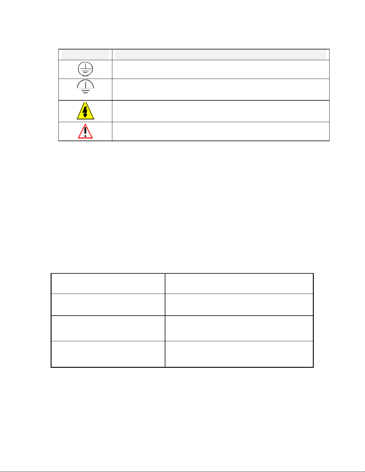
Symbol What it means
Protective ground terminal. Provided for connection of the protective earth green (green
or green/yellow) supply system conductor.
Functional ground terminal. Used for non-safety purposes such as noise immunity
improvement.
WARNING. Risk of electric shock. This symbol warns the user of a potential shock
hazard where voltages greater than 30 Vrms, 42.4 Vpeak, or 60 Vdc may be accessible.
CAUTION. When this symbol appears on the product, see the user manual for more
information. This symbol appears next to the required information in the manual.
CE conformity
This product conforms with the protection requirements of the following European Council
Directives: 89/336/EEC, the EMC directive, and 73/23/EEC, the low voltage directive. Do
not assume this product conforms with any other “CE Mark” Directive(s).
Attention
The emission limits of EN 50081-2 are designed to provide reasonable protection against harmful
interference when this equipment is operated in an industrial environment. Operation of this equipment in a
residential area may cause harmful interference. This equipment generates, uses, and can radiate radio
frequency energy and may cause interference to radio and television reception when the equipment is used
closer than 30 meters to the antenna(e). In special cases, when highly susceptible apparatus is used in close
proximity, the user may have to employ additional mitigating measures to further reduce the electromagnetic
emissions of this equipment.
Product model number:
Serial number:
Date code:
Service department telephone
number:
Page 6

Page 7

TABLE OF CONTENTS
1. OVERVIEW ............................................................................................................................................... 1-1
1.1 CLEAR AND FULLY DOCUMENTED CHART OF PEN RECORDER........................................ 1-1
1.1.1 Alarms are indicated clearly......................................................................................................... 1-2
1.2 CLEAR AND FULLY DOCUMENTED CHART FOR MULTIPOINT RECORDER................... 1-3
1.2.1 Alarms are indicated clearly......................................................................................................... 1-4
2. INSTALLATION ....................................................................................................................................... 2-1
2.1 WARNING .............................................................................................................................................. 2-1
2.2 UNPACKING.......................................................................................................................................... 2-2
2.3 PANEL MOUNTING THE RECORDER............................................................................................ 2-3
2.3.1 Recommendations........................................................................................................................ 2-3
2.3.2 External dimensions and cut-out.................................................................................................. 2-3
2.3.3 Installing the recorder................................................................................................................... 2-4
2.4 WIRING THE RECORDER ................................................................................................................. 2-5
2.4.1 Recommendations........................................................................................................................ 2-5
2.4.2 Terminal connections................................................................................................................... 2-6
2.5 PREPARING POWER-UP.................................................................................................................... 2-7
2.5.1 Installing the printing system ....................................................................................................... 2-7
2.5.2 Fitting the roll chart.................................................................................................................... 2-12
2.5.3 Fitting the fanfold chart.............................................................................................................. 2-13
2.6 CLEANING THE PANE...................................................................................................................... 2-13
2.7 CARRIAGE CALIBRATION ............................................................................................................. 2-14
2.7.1 Chart certification....................................................................................................................... 2-14
2.7.2 Carriage calibration (or chart calibration) .................................................................................. 2-15
2.8 CHECK LIST........................................................................................................................................ 2-17
2.9 REPLACING THE INK CARTRIDGES........................................................................................... 2-17
3. CONFIGURATION................................................................................................................................... 3-1
3.1 FUNCTION KEYS ................................................................................................................................. 3-1
3.1.1 SETUP ......................................................................................................................................... 3-1
3.1.2 ENTER......................................................................................................................................... 3-1
3.1.3 INCREMENT .............................................................................................................................. 3-1
3.1.4 DECREMENT ............................................................................................................................. 3-2
3.2 MAIN MENU .......................................................................................................................................... 3-2
3.3 ALARMS................................................................................................................................................. 3-2
3.4 SPEED ..................................................................................................................................................... 3-4
3.4.1 SPEED (mm/hour) ....................................................................................................................... 3-4
3.4.2 SPEED (inches/hour) ................................................................................................................... 3-5
3.5 IDENTIFICATION ................................................................................................................................ 3-6
3.6 TIME........................................................................................................................................................ 3-7
3.7 DATE ....................................................................................................................................................... 3-8
4. MODEL SELECTION GUIDE ................................................................................................................4-1
4.1 PRODUCT IDENTIFICATION............................................................................................................ 4-1
5. PRODUCT SPECIFICATION SHEET ................................................................................................... 5-1
5.1 TECHNICAL DATA.............................................................................................................................. 5-1
5.2 ACCURACY ........................................................................................................................................... 5-4
5.3 AVAILABLE RANGES ......................................................................................................................... 5-5
5.4 DIMENSIONS......................................................................................................................................... 5-6
5.5 TERMINAL CONNECTIONS.............................................................................................................. 5-7
i
Page 8

TABLE OF CONTENTS
6. CONFIGURATION................................................................................................................................... 6-1
6.1 ANALOG INPUT CONFIGURATION................................................................................................ 6-1
6.2 RELAY OUTPUT CONFIGURATION ............................................................................................... 6-2
7. CALIBRATION ......................................................................................................................................... 7-1
7.1 FIELD CALIBRATION......................................................................................................................... 7-1
8. PC CONFIGURATION............................................................................................................................. 8-1
8.1 OVERVIEW............................................................................................................................................ 8-1
8.2 PRODUCT FEATURES ........................................................................................................................ 8-1
8.3 INSTALLATION.................................................................................................................................... 8-1
8.3.1 System Requirements................................................................................................................... 8-1
8.3.2 New installation ........................................................................................................................... 8-2
8.3.3 Upgrade old installation ............................................................................................................... 8-5
8.3.4 Uninstall....................................................................................................................................... 8-6
8.4 USE .......................................................................................................................................................... 8-7
8.4.1 Start up ......................................................................................................................................... 8-7
8.4.2 Menus........................................................................................................................................... 8-7
8.4.3 Modifying fields of parameters.................................................................................................... 8-7
8.4.4 Going from a parameter field to another one ...............................................................................8-7
8.4.5 Leaving a menu............................................................................................................................ 8-8
8.4.6 Saving modifications on a file...................................................................................................... 8-8
8.5 READ AND MODIFY PARAMETERS ............................................................................................... 8-9
8.6 DIAGNOSTIC PARAMETERS.......................................................................................................... 8-11
9. TROUBLESHOOTING ............................................................................................................................ 9-1
9.1 FAILURE SYMPTOMS AND TROUBLESHOOTING PROCEDURES ........................................ 9-1
9.2 TROUBLESHOOTING LIST ............................................................................................................... 9-1
9.2.1 Self test mode pen recorder.......................................................................................................... 9-1
9.2.2 Self test mode multipoint recorder............................................................................................... 9-5
9.2.3 Symptom: The recorder is inoperative ......................................................................................... 9-8
9.2.4 Symptom: The chart is inoperative ..............................................................................................9-8
9.2.5 Symptom: The print carriage is inoperative................................................................................. 9-9
9.2.6 Symptom: The print head is inoperative ...................................................................................... 9-9
9.2.7 Symptom: Printing incorrect color............................................................................................. 9-10
9.2.8 Symptom: Wrong date/time ....................................................................................................... 9-10
9.2.9 Symptom: The alram relay is inoperative ..................................................................................9-10
9.2.10 Symptom: Analog input out of tolerance ...................................................................................9-11
9.2.11 Symptom: Incorrect spacing between points.............................................................................. 9-11
9.2.12 Symptom: No communication with PC loader........................................................................... 9-12
9.2.13 Symptom: Printed traces are unstable ........................................................................................ 9-12
9.2.14 Symptom: Chart illumination failed........................................................................................... 9-12
10. KITS LIST ................................................................................................................................................ 10-1
10.1 ELECTRONIC PARTS ....................................................................................................................... 10-2
10.2 MECHANICAL PARTS ...................................................................................................................... 10-3
10.3 MISCELLANEOUS ............................................................................................................................. 10-4
10.4 CONSUMABLES ................................................................................................................................. 10-5
SAFETY
SALES AND SERVICE
ii
Page 9
1. OVERVIEW
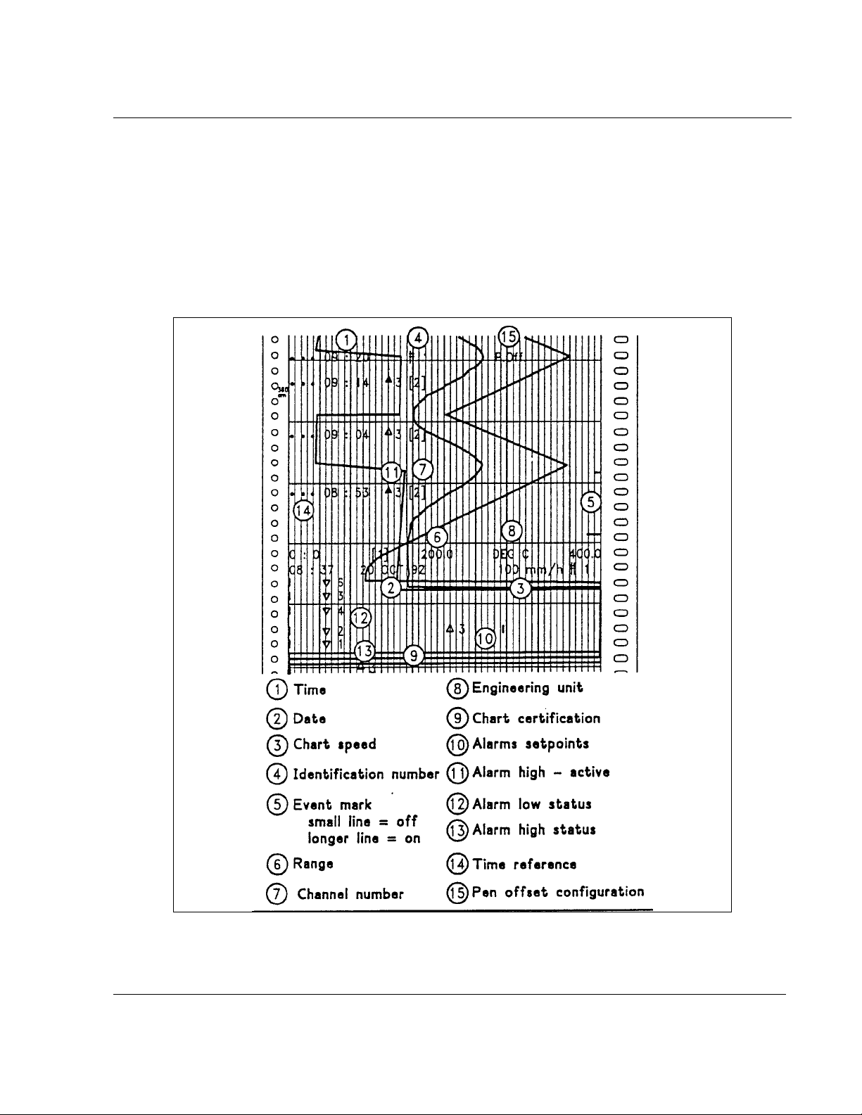
1.1 CLEAR AND FULLY DOCUMENTED CHART OF PEN RECORDER
Color traces :
Pen 1 = blue
Pen 2 = red
Pen 3 = green
1-1
Page 10

1.1.1 Alarms are indicated clearly
1. OVERVIEW
1-2
Page 11
1. OVERVIEW
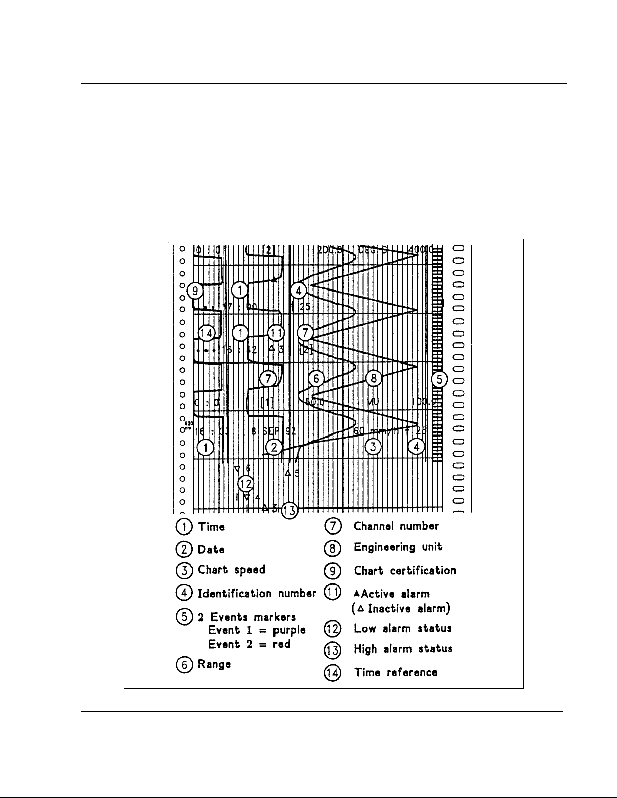
1.2 CLEAR AND FULLY DOCUMENTED CHART FOR MULTIPOINT RECORDER
Color traces
Channel 1 = purple Channel 4 = green
Channel 2 = red Channel 5 = blue
Channel 3 = black Channel 6 = brow n
1-3
Page 12

1.2.1 Alarms are indicated clearly
1. OVERVIEW
1-4
Page 13

2. INSTALLATION
2.1 WARNING
IMPROPER INSTALLATION
To avoid the risk of electrical shock which could cause personal injury, follow all safety
!
! POWER SUPPLY
Ensure the source voltage matches the voltage of the power supply before turning on the power.
! PROTECTIVE GROUNDING
Make sure to connect the protective grounding to prevent an electric shock before turning on the power.
! NECESSITY OF PROTECTIVE GROUNDING
To avoid a potential shock hazard, never cut off the internal or external protective grounding wire or
disconnect the wiring of protective grounding terminal.
! DEFECT OF PROTECTIVE GROUNDING AND FUSE
Do not operate the instrument when protective grounding or fuse might be defective.
! FUSE
To prevent a fire, make sure to use the fuse with specified standard (current voltage, type). Before
replacing the fuse, turn off the power and disconnect the power source. Do not use a different fuse
or short-circuit the fuseholder.
! DO NOT OPERATE IN AN EXPLOSIVE ATMOSPHERE
Do not operate the instrument in the presence of flammable liquids or vapors. Operation of any
electrical instrument in such an environment constitutes a safety hazard.
! NEVER TOUCH THE INTERIOR OF THE INSTRUMENT
Inside this instrument there are areas of high voltage; therefore, never touch the interior if the
power supply is connected. This instrument has an internal changeable system; however, internal
inspection and adjustments should be done by qualified personnel only.
! EXTERNAL CONNECTION
To ground securely, connect the protective grounding before connecting to measurement or control
unit.
! If the equipment is used in a manner not specified by the manufacturer, the protection provided by
the equipment may be impaired.
! Do not replace any component (or part) not explicitly specified as replaceable by your supplier.
notices in this documentation.
Protective earth terminal. Provided for connection of the protective earth supply system
conductor.
Failure to comply with these instructions could result in death or serious injury
2-1
Page 14

2.2 UNPACKING
Remove the accessories and check them against the figure below.
2. INSTALLATION
1. Ink cartridge(s) (A) or ink wheel (B)
2. Fuse (Spare) (Use only 1 A T. fuses)
3. Roll (R) or fanfold (Z) chart
4. Mounting brackets with nuts
5. Operator manual
6. Front label
NOTE: In case of missing item, please contact your nearest sales office.
2-2
Page 15
2. INSTALLATION
2.3 PANEL MOUNTING THE RECORDER
2.3.1 Recommendations
This recorder is designed to operate under specific conditions. If you need more information, refer to
the product specification sheet.
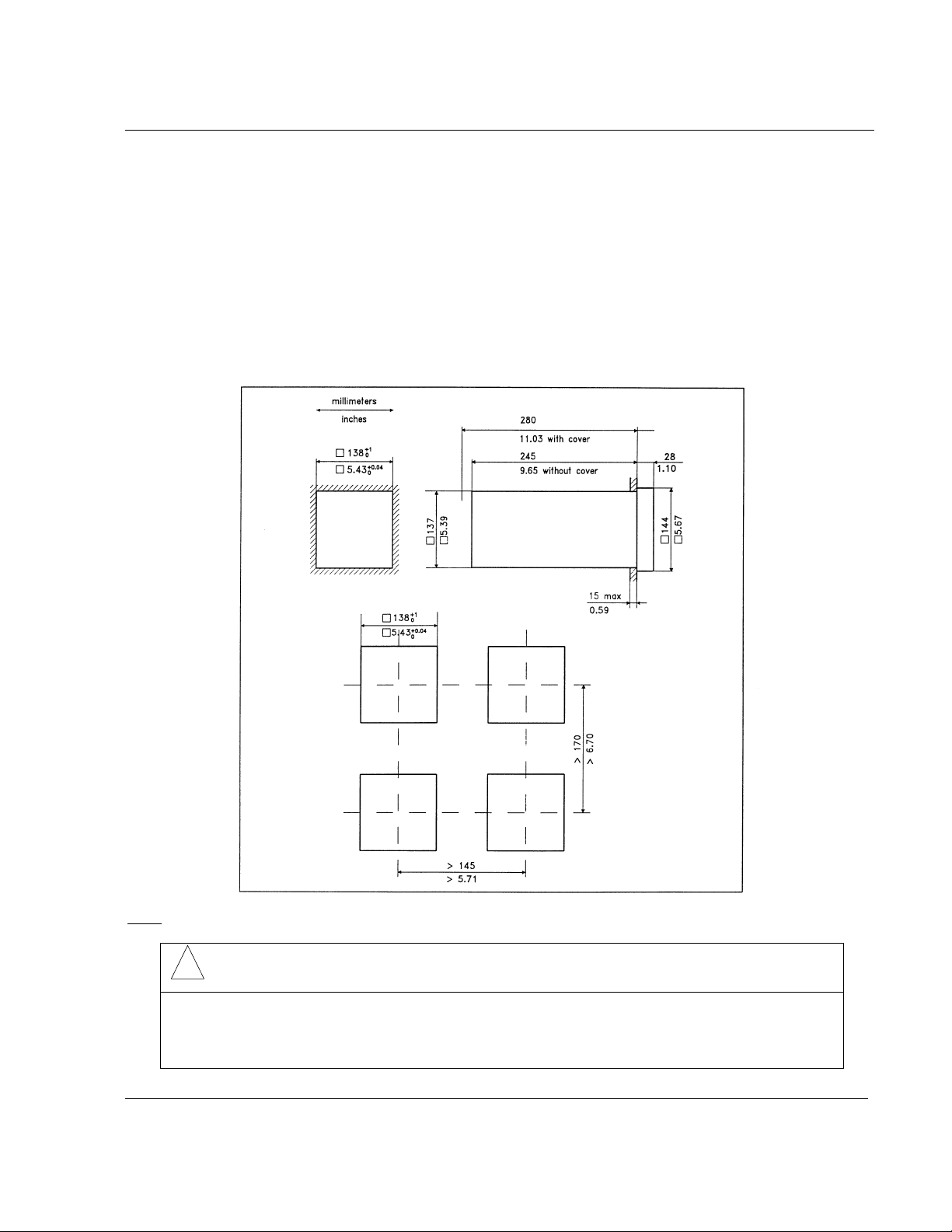
2.3.2 External dimensions and cut-out
Prepare panel cut-out as detailed below:
: Maximum panel thickness 15 mm
Note
!
CAUTION
The maximum temperature inside the cabinet should not exceed the ambient conditions
specific to the recorders. The recorder must be mounted into a panel to limit operator
access to the rear terminals.
Failure to comply with these instructions may result in product damage
2-3
Page 16

2.3.3 Installing the recorder
To install the recorder, follow the figures below:
Mounting brackets
2. INSTALLATION
Mounting angle limits
2-4
Page 17
2. INSTALLATION
2.4 WIRING THE RECORDER
2.4.1 Recommendations
# All wiring must be in accordance with local norms and carried out by authorized experienced
personnel.
# The ground terminal must be connected before any other wiring (and disconnected last).
# A switch in the main power supply wiring is required near the equipment.
# If an external fuse is used to protect the line supply to the recorder, the fuse should match the
recorder fuse rating (fuse type) as well as for the fuseholder.
# Sensor wiring should be run as far as possible from power wiring.
# To reduce stray pick-up, we recommend the use of twisted pair sensor wiring.
# EMI effects can be further reduced by the use of shielded cable sensor wiring. The shield must be
connected to the ground terminal:
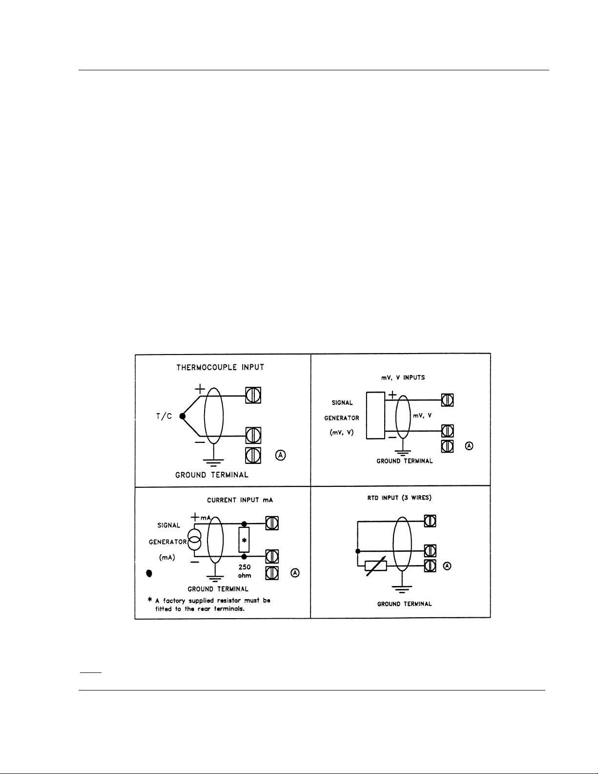
: Terminal (A) is only used for RTD. (See diagrams above.)
Note
2-5
Page 18

2.4.2 Terminal connections
2. INSTALLATION
2-6
Page 19

2.5 PREPARING POWER-UP
2.5.1 Installing the printing system
Remove the chart cassette from the chassis as shown below:
2. INSTALLATION
2-7
Page 20

If you have a pen recorder, proceed as shown below:
Open the front display after having removed the chart cassette.
2. INSTALLATION
Insert the pen cartridges.
2-8
Page 21
2. INSTALLATION
Inserted pen cartridges
!
CAUTION
Do not move the print head mechanism when the recorder is working.
Failure to comply with these instructions may result in product damage
2-9
Page 22

If you have a multipoint recorder, proceed as shown below:
Open the front scale after having removed the chart cassette.
2. INSTALLATION
Insert the ink wheel.
: The ink wheel should be inserted and rotated counter-clockwise until ratchet engages.
Note
2-10
Page 23

2. INSTALLATION
!
CAUTION
Do not move the print head mechanism when the recorder is working.
Failure to comply with these instructions may result in product damage
2-11
Page 24

2. INSTALLATION
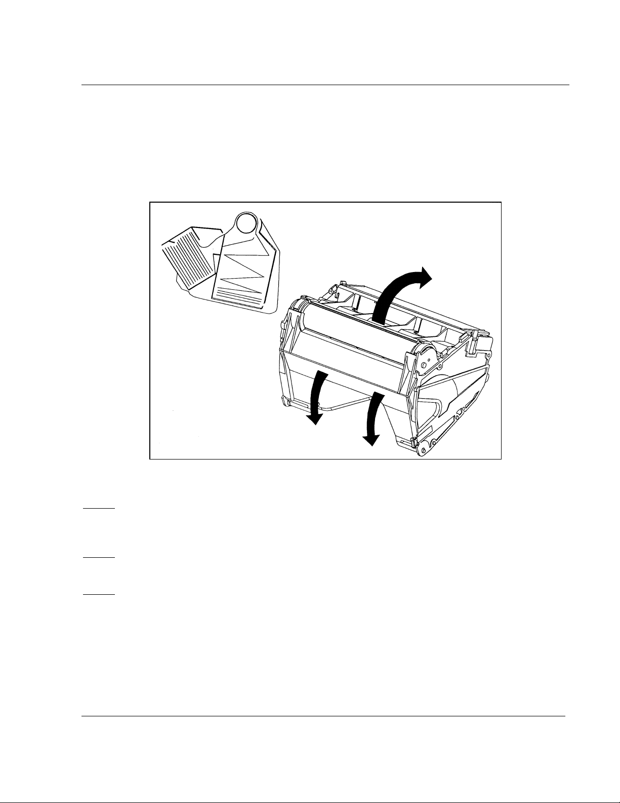
2.5.2 Fitting the roll chart
Open the chart cassette as shown below and install the chart using the figure on the cassette.
Note 1
If required, the chart cassette can be cleaned with a damp cotton cloth.
Note 2
Note 3
: To maintain print quality, the print carriage guide rods should be cleaned at six-monthly
intervals with a dry cotton cloth. Lubricant should NOT be used.
: On completion, close the front scale(s) before reinserting the chart cassette in the printing
position.
: After a change of paper it is recommended to check the chart with calibration and to adjust it
if necessary (Refer to section 2.7 CARRIAGE CALIBRATION).
2-12
Page 25
2. INSTALLATION
2.5.3 Fitting the fanfold chart
• Open the chart cassette as shown below and install the chart using the figure on the cassette.
• Place the fanfold chart in the upper compartment with the folds in the vertical plane and the slots
on the right hand side.
• Pull out 4 folds of paper and then close the rear metal cover.
Note 1
If required, the chart cassette can be cleaned with a damp cotton cloth.
Note 2
Note 3
: To maintain print quality, the print carriage guide rods should be cleaned at six-monthly
intervals with a dry cotton cloth. Lubricant should NOT be used.
: On completion, close the front scale(s) before reinserting the chart cassette in the printing
position.
: After a change of paper it is recommended to check the chart with calibration and to adjust it
if necessary (Refer to section 2.7 CARRIAGE CALIBRATION).
2.6 CLEANING THE PANE
It is recommended to clean the recorder pane with a soft cloth and the following products:
• Light soapy water
• Methylated spirit
2-13
Page 26

2.7 CARRIAGE CALIBRATION
2.7.1 Chart certification
ON PEN RECORDER
2. INSTALLATION
Figure 2-1
If the trace of one or several pens are not correctly on 0 % or 100 % (see ref. A, fig. 2-1) of the chart,
make a carriage calibration.
ON MULTIPOINT RECORDER
Figure 2-2
If the trace is not correctly on 0 % or 100 % (see ref. B, fig. 2-2) of the chart, make a carriage
calibration.
2-14
Page 27

2. INSTALLATION
2.7.2 Carriage calibration (or chart calibration)
This operation allows the 0 % and 100 % calibration of the traces on the paper.
• The CALIBRATION mode is "hidden" and can only be accessed by a special combination of
Function Keys when in the RUN mode.
• To enter the CALIBRATION mode, press both
print the channel numbers.
For a one-pen recorder: available channel number is 1 only.
For a two-pen recorder: available channel numbers are 1 and 2.
For a three-pen recorder: available channel numbers are 1, 2 and 3.
For a multipoint recorder: available channel numbers are 1, 2, 3, 4, 5 and 6.
When printing completed, the pointer will be positioned on channel 1.
On a multipoint recorder, the chart calibration is made once for all channels, whatever the channel you
choose.
ENTER
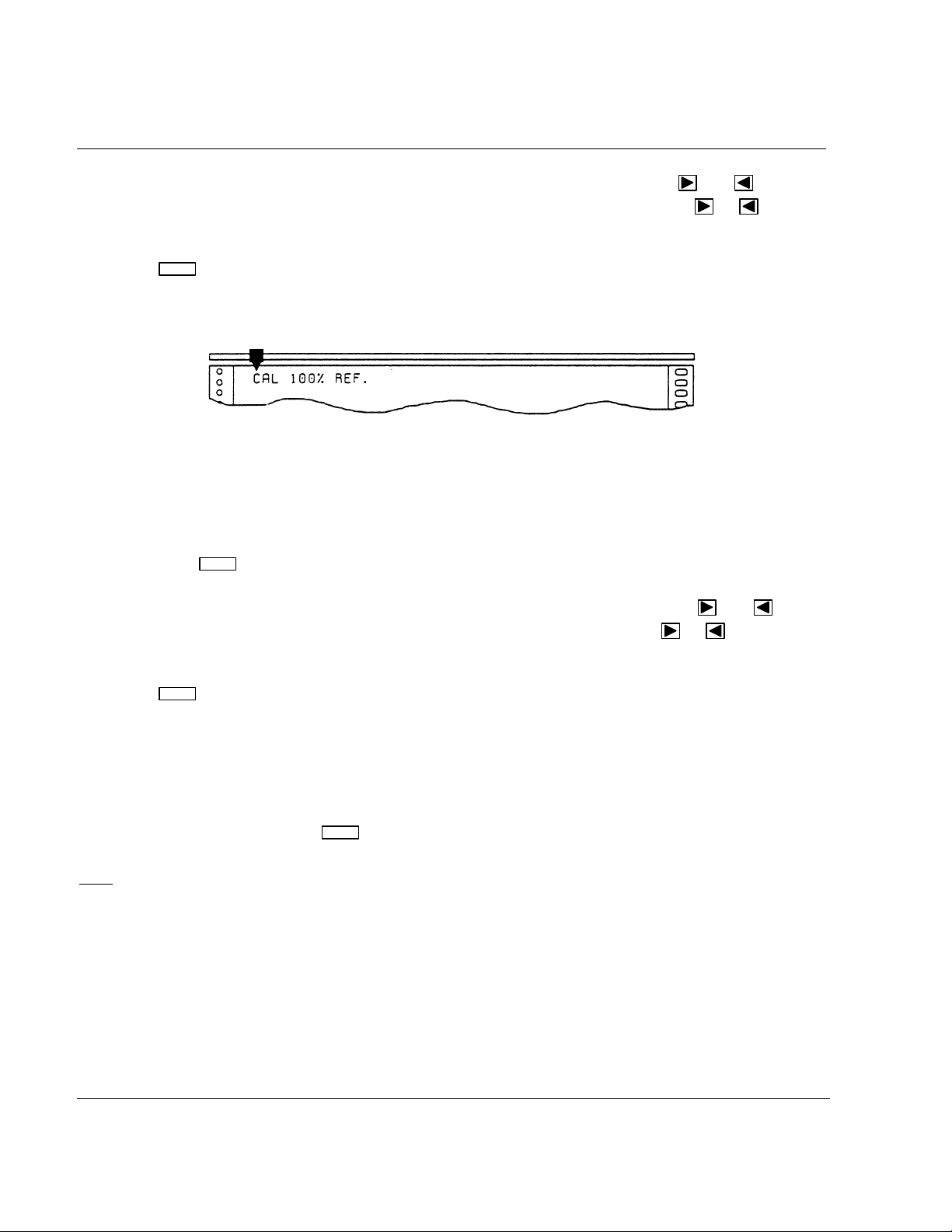
• Press
Now the recorder prints a message indicating that it will calibrate the 0 % of the chart on the chosen
channel.
to confirm your choice (your choice will be highlighted).
and FOR 10 SECONDS and the recorder will
NOTICE
The sensor MUST either be disconnected, or the input voltage shall not change of more than
25 % of the span during the whole operation.
Then press
ENTER
to start the 0 % calibration.
2-15
Page 28
2. INSTALLATION
Now the pointer will take up the current 0 % calibration position. If necessary, the
be used to position the pen to 0 %. The chart will advance by one line each time the
pressed and the recorder will reprint its mechanical references and be positioned on its new value.
ENTER
• Press
to confirm the new 0 % carriage calibration.
Now the recorder prints a message indicating that the 100 % of the span will be calibrated:
and keys can
or keys are
• To adjust the carriage calibration keep the input terminals open or keep the sensor connected, but
be sure that the voltage given by this sensor have not changed from more than 25 % of the span
since the 0 % calibration.
ENTER
• Then press
to start the 100 % calibration.
Now the pointer will take up the current 100 % calibration position. If necessary, the
can be used to position the pen to 100 %. The chart will advance each time the
and keys
or keys are
pressed.
ENTER
• Press
to confirm the new 100 % calibration.
Calibration is now complete and the recorder will reprint the calibration menu.
• At this point, if necessary, the recorder will print again the channel numbers to allow you to select
another channel to calibrate.
SETUP
• To return to RUN mode, the
key should be pressed for a few seconds.
: If the difference between the 100 % and 0 % reference signals is under 25 %, then only the
Note
carriage calibration is made; otherwise the operation will be considered as a full "field calibration".
In case of faulty operation, you would have to provide again a complete field calibration (note that, if
you have a PC LOADER, you can find back the factory calibration only by changing the configured
range and coming back to the previous one).
2-16
Page 29

2.8 CHECK LIST
1 Have you connected the ground terminal?
2 Have you connected the sensor(s) correctly? (Wire type, polarity, etc.)
3 Have you tightened all terminal screws?
4 Have you installed the ink cartridge(s) or wheel?
(See figures on pages 2-8 to 2-13.)
5 Have you installed the chart correctly?
(See figures on pages 2-14 and 2-15.)
2. INSTALLATION
6 Have you closed the front scale?
7 Have you fitted the chart cassette in the recorder?
8 Have you programmed the right scale with your PC Loader?
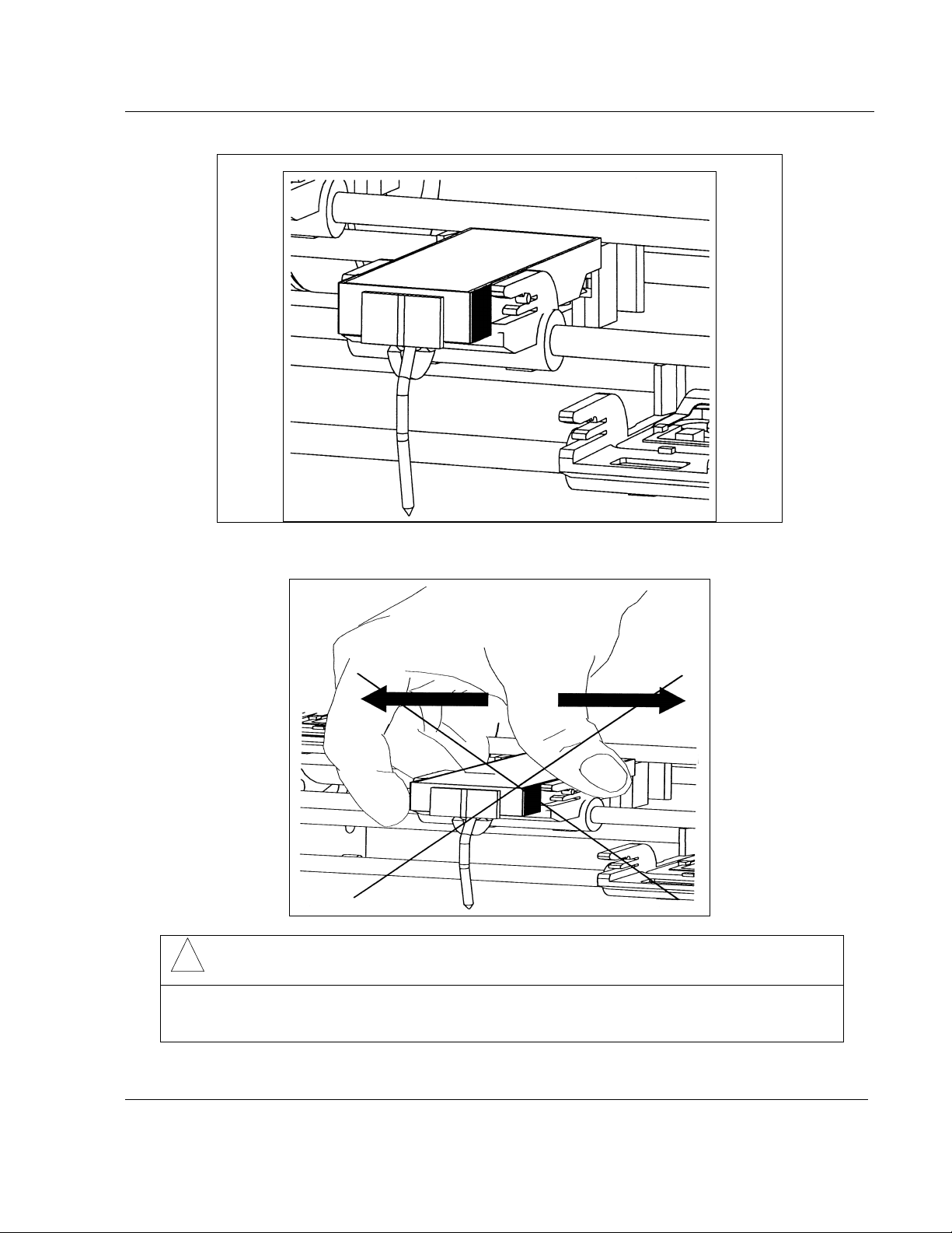
2.9 REPLACING THE INK CARTRIDGES
• Remove the chart cassette. The print carriage stops to allow you to replace the ink cartridges.
• Open the front scale.
• For the pen recorders:
- Pull the ink cartridge forward and remove from its housing.
- The new ink cartridge must be fully pushed home.
• For the multipoint recorder:
- Hold the print carriage with the left hand and pull the ink wheel to the right and remove from
its support.
- The new ink wheel should be inserted and rotated counter-clockwise until ratchet engages.
• Close the front scale.
• Reinsert the chart cassette in printing position.
: When pen recorders are not used for long periods of time, it is recommended that the ink
Note
cartridges be removed and capped.
2-17
Page 30

2. INSTALLATION
2-18
Page 31

3.1 FUNCTION KEYS
3. CONFIGURATION
3.1.1 SETUP
SETUP
The key has three functions.
• Entering CONFIGUR ATI ON main menu from the RUN mode.
• Exiting CONFIGU R AT I ON main menu to normal RUN mode.
• Exiting CONFIGURATION sub-menus (ALARMS, SPEED, ID, TIME, DATE) to return to the main
menu.
3.1.2 ENTER
ENTER
The key allows confirmation of your choice of a sub-menu or a parameter.
3.1.3 INCREMENT
The
• Advancing chart in run mode. The chart advances unt i l the key is released.
key has 2 functions:
• Moving the pointer in confi guration mode.
The
Note
key has no effect. If you w ant to move the pointer to t he l eft, use the
key moves the pointer to the right and pl aces i t at the sub-menu or parameter to be changed.
: When the pointer is placed eit her on t he l ast sub-menu or on the last parameter t o t he ri ght, this
key.
3-1
Page 32

3. CONFIGURATION
3.1.4 DECREMENT
The
Note: When the pointer is pl aced ei t her on the first sub-menu or on the first parameter to the left, this
key has no effect. If you w ant to move the pointer to t he ri ght , use the
3.2 MAIN MENU
The recorder automatically prints any m odi fication to the configurat i on.
• To access the main menu, press
The recorder will print the main menu:
key moves the pointer to the lef t and places it at the sub-menu or param et er to be changed.
key.
SETUP
for a few seconds.
When printing completed, the pointer will be positioned at the ALARMS sub-menu. If there is no
action, the recorder returns to the RU N mode after a few minutes.
• Press
wish to modify.
• Note 1
• Note 2
return to RUN mode.
to move the pointer to the right and place on the desired sub-menu or parameter you
: To return to the normal RUN m ode, press the
: When existing configuration mode, the recorder will reprint its mechanical references and
SETUP
key for a few seconds.
3.3 ALARMS
• When the pointer is positioned at ALARMS:
3-2
Page 33

• Press
3. CONFIGURATION
ENTER
to confirm your choice and the recorder prints the ALARMS sub-menu:
The printed numbers refer to ALARMS numbers. F or ex am pl e, the digit 1 represents alarm number 1.
• Press
• Press
or to point to the desired al arm num ber.
ENTER
to confirm your choice. (Your choice will be highlighted)
The pen carriage moves to indicate the posit i on of the alarm setpoint on the scale.
• Pressing
• Press
or modifies the pen position from initial position to the new required position.
ENTER
to confirm the new value. The content of ALARMS sub-menu will be reprinted.
IMPORTANT
: Unless modified by PC and configuration software, t he standard alarm configuration is
shown below.
• For a One-pen recorder: Alarm numbers are 1 and 2.
• For a Two-pen recorder: Alarm numbers are 1, 2, 3 and 4.
• For a Three-pen recorder: Alarm numbers are 1 to 6.
• For a Multipoint recorder: Alarm numbers are 1 to 6.
:
Note
• The alarm type (High or Low) is pre-configured but may be m odi f ied via PC and configuration
software.
PEN RECORDER MULTIPOINT RECORDER
ALARM
NUMBER
TYPE PEN ALARM
TYPE CHANNEL
NUMBER
1 Low Pen 1 1 High Channel 1
2 High Pen 1 2 High Channel 2
3 Low Pen 2 3 High Channel 3
4 High Pen 2 4 High Channel 4
5 Low Pen 3 5 High Channel 5
6 High Pen 3 6 High Channel 6
3-3
Page 34

Alarm type and set point are printed each t i m e the recorder is powered.
3. CONFIGURATION
High Alarm ON
High Alarm OFF
Low Alarm ON
Low Alarm OFF
• The operation can be repeated for other ALARMS or the ALARMS sub-menu can be left by pressing
SETUP
the
key for a few seconds, so that you will return to the main menu.
3.4 SPEED
This menu permits configuration of chart speed #1. Selection of units (mm/ or inches per hour) and
chart speed #2 are pre-configured as defined in your order.
3.4.1 SPEED (mm/hour)
• When the pointer is positi oned at SPEED 1:
• Press
ENTER
and the recorder prints current speed #1:
When printing completed, the pointer will be positioned at the leading digit, in this case 0.
• Press
or to select the position of digit to be changed.
For example, position the poi nt er on the digit 3. The minim um speed i s 10 m m /h and maximum speeds
are 6000 mm/h for pen recorders and 1500 mm/h for the multipoint.
ENTER
• Press
to confirm your choice of position and the recorder will print the choice of values
which can be selected. (Your choice will be highlighted).
3-4
Page 35

3. CONFIGURATION
In this example, the pointer will be positioned at the current value, in this case 3.
• Press
• Press
• At this point, if necessary, the position of t he nex t digit to be changed can be made and follow ed
by selection of value.
• To return to the main menu, the
3.4.2 SPEED (inches/hour)
• When the pointer is positi oned at SPEED 1:
or to move the pointer t o t he desi red v al ue, for example 1.
ENTER
to confirm the change and the new speed of 160 mm/h will be printed.
SETUP
key should be pressed for a few seconds.
• Press
ENTER
and the recorder prints current speed #1:
When printing completed, the pointer will be positioned at the leading digit, in this case 0.
• Press
or to select the posit i on of digit to be changed, for exam pl e 0 . T he m i nimum speed is
0.5 inch/h and the maximum speeds are 240 inch/h for the pen recorders and 60 inch/h for the
multipoint.
ENTER
• Press
to confirm your choice and the recorder print s choi ce of value which can be selected.
(Your choice will be highlighted)
• Press
• Press
or to move the pointer t o t he desi red v al ue, for example 2.
ENTER
to confirm your choice and the new speed of 20.75 inch/h will be printed.
• At this point, if necessary, the position of t he nex t digit to be changed can be made and follow ed
by selection of value.
• To return to the main menu, the
SETUP
key should be pressed for a few seconds.
: Choices available for least signi f i cant digit are 0 or 5 only.
Note
3-5
Page 36

3. CONFIGURATION
3.5 IDENTIFICATION
This menu permits configuration of a speci fic ID (1 to 99) for t he recorder.
• When the pointer is positioned at ID (IDENTIF I CAT I O N OR ADDRESS NUMBER):
ENTER
• Press
and the recorder prints the current identifi cation number:
When printing completed, the pointer will be positioned at the leading digit, in this case 1.
• Select the digit t o be changed by pressing
ENTER
• Press
to confirm your selection (Your choice will be highlighted) and the recorder prints
or , for example 7.
choice of values which may be select ed.
When printing completed, the pointer will be positioned to the current value, in this case 7.
• Press
• Press
or to position the pointer to the desired value, for exampl e 4 .
ENTER
to confirm your choice and the new identification 14 will be printed.
• At this point, the sel ection of the next digit requi ri ng m odi fication can be made.
• To return to the main menu, the
SETUP
key should be pressed for a few seconds.
3-6
Page 37

3.6 TIME
• When the pointer is positi oned at T I M E:
3. CONFIGURATION
ENTER
Press
to confirm your choice and the recorder prints t he current time:
When printing completed, the pointer will be positioned at the leading digit, in this case 2.
• Press
or to choose the position you w i sh to modify, for example 1.
: It is recommended that t he l east significant position i n m inute units be set last to ensure a
Note
precise time configuration.
ENTER
• Press
to confirm your choice (Your choice will be highlighted) and the recorder prints choice
of values which may be selected.
When printing completed, the pointer will be positioned at the current value, in this case 1.
• Press
• Press
or to choose another value, for ex am pl e 2 .
ENTER
to confirm your choice and the new time of 22:47 will be printed.
Note
: The internal recorder clock is corrected/modi f i ed w hen
ENTER
is pressed.
• A this point, if necessary , the position of the next di git to be changed can be made, followed by
selection of value.
SETUP
• To return to the main menu, the
key should be pressed for a few seconds.
3-7
Page 38

3.7 DATE
• When the pointer is positi oned at DATE:
3. CONFIGURATION
ENTER
• Press
to confirm your choice and the recorder prints the current date:
When printing completed, the pointer will be positioned at the leading position, in this case 1.
• Press
• Press
or to choose the position you w i sh to modify, in this ex am pl e 8.
ENTER
to confirm your choice. (Your choice will be highlighted)
The recorder prints the range of values which may be select ed.
When printing completed, the pointer will be positioned at the current value, in this case 8.
• Press
• Press
or to choose another value, for ex am pl e 9 .
ENTER
to confirm your choice and the new date will be printed: 19 FEB 93.
• At this point, if necessary, the position of t he nex t digit to be changed can be made and follow ed
by selection of value.
• To return to the main menu, the
SETUP
key should be pressed for a few seconds.
3-8
Page 39

4. MODEL SELECTION GUIDE
g
p
_ _ _ _ _
-
_ _ _ _ _ _
-
_
-_-
-_-_-
_ _ _ _ _
-
V
_ _ _
_ _
g
g
p
3
g
g
g
4.1 PRODUCT IDENTIFICATION
Instructions
Select the desired Key Number. The arrow to the right marks the selections available.
Make one selection each from Tables I throu
A com
lete Model Number must have the designated number of digits in each table.
h IX.
Key Numbers
I II III IV V VI VII
_ _
_
III IX
KEY NUMBER Selection Availability
Description
1 Pen
Recor der De
Deg. C 1 Scale to Input 1 DA101
. F DA111
2 Pen Deg. C 2 Scales to Inputs 1 and 2 DA102
Recor der De
3 Pen Deg. C 3 Scales to In
Recor der De
. F DA112
uts 1, 2, and
DA103
. F DA113
3 Channel Deg. C 1 Scale 0 to 100 Linear DB103
Recor der De
. F DB113
6 Channel Deg. C 1 Scale 0 to 100 Linear DB106
Recor der De
. F DB116
4-1
Page 40

4. MODEL SELECTION GUIDE
g
0
0
0
0
0
0
0
p
0
0
0
0
p
5
5
5
5
3
t
0
0
0
0
(
)
0
0
6
Availability
DB1 _ _
DA1 _ _
0101010101
1122333366
TABLE I RANGE/SCALE
Table 1 Specify 6 digits
Format 1 per Input
None 0
T/C Deg. C De
J -50 to 150 -100 to 300 A
J 0 to 400 0 to 800 B
J 0 to 800 0 to 1500 C
K 0 to 400 0 to 800 D
K 0 to 800 0 to 1500 E
K 0 to 1200 0 to 2400 F
Upscale K 0 to 1400 0 to 2500 X
Burnout N 0 to 400 0 to 800 G
N 0 to 800 0 to 1500 H
N 0 to 1200 0 to 2400 I
N 0 to 1400 0 to 2500 Y
S 0 to 1600 0 to 3000 J
R 0 to 1600 0 to 3000 Q
T -100 to 200 -150 to 400 K
0 to 150 0 to 300 L
T
T 50 to 150 100 to 300 M
-50 to 50 -60 to 140 7
RTD Pt -50 to 150 -100 to 300 N
Burnout 100 0 to 100 0 to 200 P
Fixed -200 to 200 -300 to 400 R
Upscale 0 to 400 0 to 800 S
. F
TABLE I RANGE/SCALE, continued
Linear
mV 0 to 1
0 to 2
0 to 10
Linear U
scale 10 to 5
0 to 5
Scale Burnout 0 to 10
0 to 1
0 to 2
0 to 5
10 to 5
0 to 10
T
U
V
W
Z
Only V 0 to 1 0 to 1 1
scale 0 to
U
Burnout 1 to
V Burnou
0 to 1
0 to
1 to
0 to 1
2
4
Fixed Down
Note 4, 6
mA Burnout 0 to 2
Fixed 4 to 2
0 to 2
4 to 2
5
Downscale 4 to 20 SQRT 4 to 20 SQRT 8
Special Range 9
4-2
Page 41

4. MODEL SELECTION GUIDE
)
r
A _ _
)
rB _ _
)
rC _ _
)
rD _ _
rE _ _
rF _ _
rG _ _
rH _ _
_
_
_
_
_
_
_
_
_
_
_
_
_
_
p
_
_
(
)
_
_
_
_
_
_
_
_
_
_
_
_
_
_
_
_
_
_
_
_
_
_
_ _ A
_ _
_ _
_ _
_ _
p
_ _
_ _
_ _
_ _
_ _
_ _
Availability
DB1 _ _
DA1 _ _
0101010101
1122333366
TABLE II CHART SPEED Selection
Multivoltage 50 Hz (85 to 264 V
Multivoltage 50 Hz (85 to 264 V
Units Multivoltage 60 Hz (85 to 250 V
FrequencyMultivoltage 60 Hz (85 to 250 V
24 Vac/dc 50 Hz mm/h
24 Vac/dc 60 Hz inch/h
48 Vac/dc 50 Hz mm/h
48 Vac/dc 60 Hz inch/h
mm/hr Inch/hr
10 0.5 _ A _
20 0.75
30 1
50 2
60 3
100 4
120 5
150 6
Preset 180 7 _ I _
S
eed 1 200 8
Note 5
Preset 60 3
S
eed 2 100 4
240 10
300 15
360 20
600 25
720 30
1200 40
1500 60
1800 90
3600 120
4800 180
6000 240
5 0.2 _ _ 0
10 0.5
20 0.75
30 1
50 2
120 5
150 6
180 7
200 8
240 10
Chart
Speed
mm/h
inch/h
mm/h
inch/h
B
C
D
E
F
G
H
J
K
L
M
N
P
Q
R
S
T
U
V
B
C
D
E
F
G
H
I
J
K
4-3
Page 42

4. MODEL SELECTION GUIDE
_ _ M
5
_ _
p
2
_ _ P
_ _ Q
T
2
(
)
5
ccccccccc
c
DB1 _ _ Availability
DA1 _ _
TABLE II CHART SPEED, continued Selection
mm/hr Inch/hr
300 15 _ _ L
360 20
Preset 600 2
eed
S
TABLE III ALARMS (Note 1)
None 0
6 Relays - 2 Configured (Channel #1) 1
2 Relays - 2 Configured (Channel #1) 2
6 Relays - 4 Configured (Channels #1 and #2) 4
6 Relays - 6 Configured (2 on Each Channel) 5
6 Relays - (One High Alarm SP on Each Channel) 6
720 30
1200 40
1500 60
0101010101
1122333366
N
_ _ R
TABLE I V LOGIC INPU
None 0
2 Remote L1: Print Inhibit Switch A
Contacts L2: Change Speed 1 to Speed 2
2 Remote L1: Print Inhibit Switch B
Contacts L2: Event Marks
2 Remote L1: Print Inhibit Switch C
Contacts L2: Event Trace
2 Remote L1: Event Trace 1
Contacts L2: Event Trace
TABLE V CHART CASSETTE
Standard Chart: 0-100 Linear Roll R
(50 divisions) Fan Fold Z
TABLE VI DOOR AND CASE
Dark Gray Door with Latch, Plastic Window 1
Dark Gray Door Key Lock, Plastic Window 2
Portable Case
Note 2
D
dddddddddd
4-4
Page 43

4. MODEL SELECTION GUIDE
r
r
(
)
_ _ _
(
)
(
)
DB1 _ _ Availability
DA1 _ _
TABLE VII OPTIONS
None 0 _ _ _ _
Pen Offset A _ _ _ _
Rear Cove
Pen Offset and Rear Cover P _ _ _ _
UL/CSA Approval R _ _ _ _
UL/CSA Approval and Rear Cove
UL/CSA Approval and Pen Offset T _ _ _ _
UL/CSA Approval, Pen Offset and Rear Cover
None _ 0 _ _ _
Power Supply for Transmitter 24 Vdc (50 mA max)
None _ _ 0_ _
Chart Illumination _ _ C _ _
Certificate of Conformance (F2474) _ _ D _ _
Certificate of Calibration _ _ E _ _
Certificate of Conformance & Chart Illumination _ _ F _ _
Certificate of Calibration & Chart Illumination
TABLE VII OPTIONS (Continued) Selection
None _ _ _ 0 0
Remote Compensation Box Input (60 deg C All Inputs) _ _ _ 0 E
Mounting of Scale Ordered Separately
Mounting of Scale Ordered Separately
Remote Compensation Box Input (60 deg C All Inputs) _ _ _ H E
Mounting of Scale Ordered Separately
Note 4
Note 4
Note 4
Plus
Plus
Selection
G _ _ _ _
S _ _ _ _
U _ _ _ _
_ B _ _ _
_ _ G _ _
H 0
0101010101
1122333366
1122333366
TABLE VIII Specials
None 0 0 0
ST Number (Consult Honeywell IM&C Representative) X X X
TABLE IX Manuals
English EN
French FR
German GE
Italian IT
Spanish SP
Swedish SW
Dutch DU
English: U.S. Format
US
4-5
Page 44

4. MODEL SELECTION GUIDE
d
Note 1: Alarm output: "N.C." contact. Can be changed to "N.O." Alarms are configured 1 High and 1 Low on each
channel except for Selection 6 which is configured as High Alarm on each channel. The Alarm Setpoint
Value can be changed from the front key panel.
Note 2: Portable case with dark gray door, plastic window, latch, rear main switch. IEC main plug connector
and rear cover. (Not available with UL/CSA Approval.)
Note 3: Consult Factory.
Note 4: For chart range and scale configuration different than what is specified in Table I, specify Table VII
option _ _ _ H0 and complete the following table. For mV, V, and mA the input signal can be selected
within the range actuation limits (minimum range is 20%). For T/C and RTD ranges the chart range
and scale can be selected within the range actuation limits (minimum chart range is 20%). Refer to
the DPR 100 A/B scales list for available scales. The information in the table is to be entered in the
free form section of the order. Multipoint units come with a single scale.
Note 5: Speed 1 can be changed from the front key panel.
Note 6: The units are built with Universal input and are delivered with 250 ohm resistors to convert input
current signal 4-20 mA into 1-5 volts dc.***
Table for Table VII Option _ _ _ H0
Pen # Multipoint Input* Burnout** Chart Scale
(DA1XX) Channel # Signal Range Eng. Unit** Range Item #
(DB1XX)
11
22
33
4
5
6
* For mV, V, and mA, the input signal can be scaled within the actuation limits (minimum input scaling is 20%).
** Burnout is factory set as indicated in Table I. Burnout on 4-20 mA and the 0-10 volt range is fixed at downscale
burnout. All other ranges burnout can be set per customer request except RTD's which is fixed at upscale
burnout.
*** Engineering Units is 5 characters maximum.
RESTRICTIONS
Restriction Letter Available Only With Not Available With
Table Selection Table Selection
R _ _ _ _ , S _ _ _ _
c VII T _ _ _ _ , U _ _ _ _
G _ _ _ _ , P _ _ _ _
50 deg C maximun temperature limit
4-6
Page 45

5.1 TECHNICAL DATA
Technical data
Analog inputs
Pen recorder 1, 2 or 3 continuous traces. Pen 1 also prints all chart documentation.
Multipoint recorder 1 up 6 channels. Inputs are scanned by relays, galvanically isolated and
Signal source Thermocouple with individual cold junction compensation.
Field calibration A channel field calibration - 0% and 100% span - may be made to certify
Burnout T/C, mV, Volt, factory set to upscale (configurable to downscale or none).
5. PRODUCT SPECIFICATION SHEET
individually configurable to any listed actuation.
Line resistance up to 1000 ohms T/C, mV, mA, Volt
RTD Pt 100 3-wire connections, lead resistance per wire 40 Ω balanced.
input sensor loop.
RTD: inherent upscale.
mA: inherent downscale
Scanning time
Input impedance 10 Mohm for T/C, mV inputs,
Stray rejection
Logic inputs (option)
Actions
Scales
Pen
Mpt
Recording span
Scaling Per input, an analog scale is printed on the chart with the engineering unit.
mV, V, mA : 330 ms
Pen:
2 seconds at 10-60 mm/h (T/C or RTD)
1 second at 60-300 mm/h (T/C or RTD)
0.33 second at > 330 mm/h or if one linear input is selected
Multipoint:
5 seconds for 6 channels
> 1 Mohm for volt inputs.
Series mode ≥ 60 dB.
Common mode at 250 Vac ≥ 130 db.
Up to 2-dry contact input s (1.5 mA – 12Vdc)
Change chart speed 1 to speed 2
Print inhibit
Event marking :
- Pen : pen 1 used as operation marker on the right side of the chart
– Mpt : 2 traces maximum on the right side of the chart. (L
= red)
1 = purple, L2
1 analog scale per pen in accordance with the input range
1 analog scale, 0 to 100 linear.
Each input can be configured differently.
Pen offset Distance between pens: 2 mm
Chart definition: 1 step = 0.2 mm
Pen carriage speed 1 second full scale
5-1
Page 46

5. PRODUCT SPECIFICATION SHEET
Technical data
Chart length
Pen trace
Pen
Multipoint
Chart speed 1 or 2 chart speeds, fully configurable, selected by a logic input.
Speed setting Pen: 10 to 6000 mm/h (.5 to 240"/h).
Stepping chart motor Resolution 0.12 mm
Alarms (Option)
Pen 1, 2, 3 or Mpt 3 CH
Mpt (6CH)
Hysteresis
Outputs
Rating contact
Power supply
To transmitters
Power consumption
Clock timer
Format
Power interruption
Accuracy
Packaging
Weight
Front face
Depth
Front window
Front protection
Lock
Cut out
Construction
Optional
Mounting Panel mounting ± 30° from horizontal.
Wiring Rear screw terminals. Terminal modules are plugged on the instrument.
Fanfold 18 m (as DIN 16230)
Roll 24 m
1400 m per pen
250 m per color
Speed 1: fully adjustable per step of 1 mm/h, within limit
Speed 2: choice as per the model selection guide
Mpt: 10 to 1500 mm/h (.5 to 60"/h)).
2 alarm setpoints per channel, (factory set* 1 low, 1 high)
1 alarm setpoint per channel, (factory set* high)
0.5 % to 99 % of scale (factory set at 0.5 %)
Up to 6 alarm relays output contacts
1 SPST normally closed contact (may be configured into normally open
contact)
2 A, 250 VAC on resistive loads
* Other selections configured by PC
85 to 264 Vac, 50/60 Hz or 24 or 48 Vac/dc (+10 –15 % nominal)
24 Vdc, 50 mA max. (optional) (75 mA available from 100V)
3 pens: 30 VA max.
Mpt: 30 VA max.
Year, month, hour, minute can be set
Battery back-up time of 10 years with 3 years off power
-5
± 10
Pen: 3.5 kg
Mpt: 3.5 kg
144 x 144 mm according to DIN 43718
245 mm/9.7" behind panel, including terminals and line protection cover.
Polycarbonate
IP54 (IEC 529) – optionally IP55
Latch or key (DIN 43832-N)
DIN 138 x 138 mm
Silicon - free
Chart illumination
Rear terminal cover
5-2
Page 47

5. PRODUCT SPECIFCATION SHEET
Technical data
Writing
Pen
Multipoint
Noise immunity This product is in conformity with the protection requirements of the
Safety protection
Electrical insulation
Input to input
Input to ground
Input to line voltage
Line voltage to ground
Alarm relay to ground
Logic input to ground
Temperature
Ambient 0 to 50° C (32 to 122°C) with fan fold paper.
1 cartridge per pen, fibre tip, 1400 m of trace per color (blue, red,
green).
1 print wheel, 6 colors, 250 m of trace per color (purple, red, black,
green, blue, brown).
following European council directives:
• 73/23/EEC – Low Voltage directive
• 89/336/EEC – EMC Directive
Conformity of this product with any other “CE Mark” Directive(s) shall
not be assumed.
EMC Classification:
• EN 50081-2-1993 Electromagnetic Compatibility – General
Emission Standard, Part 2: Industrial Environment.
EN 50082-2-1995 Electromagnetic Compatibility – General Immunity
Standard, Part 2: Industrial Environment
Complies with IEC 414, 348 and 1010-1 installation category 2 for
personal protection.
Designed to meet UL and CSA C22.2, N142 standard (CSA approved)
Test voltage 280 Vac for 1 min (except for RTD input).
Test voltage 2.1 kVdc for 1 min.
Test voltage 2.1 kVdc for 1 min.
Test voltage 2.1 kVdc for 1 min.
Test voltage 2.1 kVdc for 1 min.
Test voltage 500 Vdc for 1 min.
0 to 60° C (32 to 140°C) with roll paper.
Optionally 0 to 60° C (32 to 140° F)
Storage -40 to 70° C (32 to 158° F)
10 to 90 % RH non condensing
Humidity
Roll
Fan fold
Vibrations Frequency:
10 to 90 % RH non-condensing
15 to 80 % RH non condensing
10 to 60 Hz – amplitude 0.07 mm
60 to 150 Hz- acceleration 1g
5-3
Page 48

5. PRODUCT SPECIFICATION SHEET
5.2 ACCURACY
Accuracy
Reference conditions
Temperature
Humidity
Line voltage nominal
Source resistance
Series mode
Common mode
Frequency nominal
Accuracy A/D converter accuracy: 0.25 % of selected input range * (IEC873).
Rated limits and associated drifts
Parameter Rated limits Influence on accuracy
Temperature 0 to 50° C
Supply voltage 85 to 264 V No influence
Source resistance T/C, mV
RTD
Humidity 10 to 90 % RH at 25°
Long-term stability 0.1 % per year
Vibrations 1.25 mm at 0 t 14 Hz
Extreme conditions
Operating
Temperature 0 to 60° C (32 to 140° F)
Humidity 10 to 90 % RH non-condensing
Storage
Temperature -40 to 70° C (-40 to 158° F)
Humidity 5 to 95 % RH non-condensing
* Refer to "Available ranges" table for exceptions
23° C ±2° C (73° F ±3° F)
65 % ±5 % RH
±1 %
0 Ω
0 V
0 V
±1 %
For a 4/20 mA input, you must add the resistor accuracy.
Cold junction accuracy: 0.5° C
Chart resolution: 0.2 mm
0.1 % per 10° C of
(32 to 122° F)
Cold junction
0.3° C/10° C
6 µV per 100 Ω of line
resistance, 1000 Ω
0.1° C per Ω in each
wire balanced leads,
40 Ω max.
0.1 % max.
C
1 g at 14 to 250 Hz
change
max.
5-4
Page 49

5. PRODUCT SPECIFICATION SHEET
5.3 AVAILABLE RANGES
Available ranges
Thermocouples
° C ° F
J -50 to 150
0 to 400
0 to 800
K 0 to 400
0 to 800
0 to 1200
0 to 1400
N (Nicrosil Nisil) 0 to 400
0 to 800
0 to 1200
0 to 1400
R 0 to 1600 0 to 3000
S 0 to 1600 0 to 3000
T -100 to 200
0 to 150
50 to 150
Note: Provision to accept T/C input for remote compensation box at
fixed temperature of 50° C or 60° C.
RTD's Pt100
(Alpha = 0.00385)
MV and Volt 0 to 10 mV
0 to 20 mV
0 to 50 mV
10 to 50 mV
0 to 100 mV
mA
* Accuracy = 1° C or 1.8° F
0 to 20 mA or 4 to 20 mA linear
4 to 20 mA SQRT
Input resistor 250 ohms required
-50 to 50*
-50 to 150*
0 to 100*
-200 to 200
0 to 400
-100 to 300
0 to 800
0 to 1500
0 to 800
0 to 1500
0 to 2400
0 to 2500
0 to 800
0 to 1500
0 to 2400
0 to 2500
-150 to 400
0 to 300
100 to 300
-60 to 140*
-100 to 300*
0 to 200*
-300 to 400
0 to 800
0 to 1 V
0 to 5 V
1 to 5 V
0 to 10 V
5-5
Page 50

5.4 DIMENSIONS
DIMENSIONS
5. PRODUCT SPECIFICATION SHEET
5-6
Page 51

5.5 TERMINAL CONNECTIONS
5. PRODUCT SPECIFICATION SHEET
5-7
Page 52

5. PRODUCT SPECIFCATION SHEET
5-8
Page 53

6. CONFIGURATION
6.1 ANALOG INPUTS CONFIGURATION
The analog input boards are hardware configured at the factory to match the specifi ed actuation type.
This hardware configuration only requires change i f a m aj or change i n actuation type is required via the
configuration jack connector.
• Configure the range(s) via t he j ack connector
(See section 9 : PC Confi guration, paragraph 9.5 "Read and modif y parameters")
• Check if the new range(s) need a hardware change on t he anal og i nput board (See figure
below)
• If so, remove power from the recorder.
• Remove the analog input term i nal bl ock.
• Change the switch position(s) with a small screw driver. (See figure below)
Push the switch completely on the high or low position.
• During the initialisation of the recorder, the relays will be in the de-energized state. (Alarm
state)
Analog input hardware configuration
6-1
Page 54

6. CONFGURATION
6.2 Analog input hardware configuration RELAY OUTPUT CONFIGURATION
All the relays are factory confi gured to be de-energized under alarm conditions.
Each relay is factory set for NC ( norm al l y cl osed) operation by a jumper on the alarm board.
If you need to reverse this operation. (See figure below)
• 5 Remove the alarm relay board. (See CK 110)
• 5 Move the jumper from the NC location (normally cl osed) to the NO location ( norm al l y open).
Jumpers configuration
6-2
Page 55

7. CALIBRATION
7.1 FIELD CALIBRATION
This menu allows the 0% and 100% calibration of each input.
!
CAUTION
The recorder should have been powered for at least 15 minutes and requires provision of
accurate signal source to match actuation/range.
Failure to comply with these instructions may result in product damage
• Verify the alignment of the 0% actuation range limit with the 0% on the chart. If wrong
alignment, undo the securing screws of the scale, reposition the scale and tighten the screws.
• The CALIBRATION menu is "hidden" and can only be accessed by a special combination of
Function Keys while in the RUN mode.
To enter the CALIBRATION mode, press both
• recorder will print the channel numbers :
! and " FOR 10 SECONDS and the
For a one-pen recorder : available channel number is 1 only.
For a two-pen recorder : available channel numbers are 1 and 2.
For a three-pen recorder : available channel numbers are 1, 2 and 3.
For a multipoint recorder : available channel numbers are 1, 2, 3, 4, 5 and 6.
When printing completed, the pointer will be positioned on channel 1.
• Press
• Press ENTER to confirm your choice. (Your choice will be highlighted)
Now the recorder prints a message indicating that a reference source corresponding to the 0 % of the
range on the chosen channel should be connected :
! or " to select the channel number you wish to calibrate.
7-1
Page 56

7. CALIBRATION
NOTICE
The source MUST correspond to the 0 and 100 % actuation input limits (total input
range) for the channel and take into account the effect of cold junction temperature and
thermocouple actuations.
• If you need to adjust the carriage calibration and analog calibration, connect your 0 % reference
signal.
Then press ENTER to start the 0 % calibration.
Now the pointer will take up the current 0 % calibration position. If necessary, the
keys can be used to position the pen to 0 %. Chart will advance by one line each time the
! or " keys are pressed. Each time the ! or " keys are pressed, the recorder will
reprint its mechanical references and be positioned on its new value.
• Press ENTER to confirm the new 0 % calibration.
It can take some seconds for the A/D converter to be calibrated.
Now the recorder prints a message indicating that a reference source corresponding to 100 %
of the range on the chosen channel should be connected :
• If you need to adjust the carriage calibration and analog calibration, connect your 100 %
reference signal.
Then press ENTER to start the 100 % calibration.
Now the pointer will take up the current 100 % calibration position. If necessary, the
" keys can be used to position the pen to 100 %. Chart will advance by one line each time
the
! or " keys are pressed.
• Press ENTER to confirm the new 100 % calibration.
Calibration is now complete and the recorder will reprint the calibration menu.
• At this point, if necessary, the position of the next channel to be changed can be made and
followed by selection of value.
• To return to RUN mode, the SETUP key should be pressed for a few seconds.
Note: If the difference between the 100 % and 0 % reference signals is under 25 % of the full
span, then the analog calibration is canceled, only a carriage calibration has been made
during this operation.
Extended values for thermocouple K and N are :
K 1400 oC = 55.824 mV
N 1400 oC = 51.067 mV
N 2500 oF = 50.026 mV
! and "
! and
7-2
Page 57

8. PC CONFIGURATION
8.1 OVERVIEW
You have just received your application software package. This tool has been designed to modify,
upload/download and store the recorder configuration.
8.2 PRODUCT FEATURES
The main functions of this software are :
• Reading the configuration of your recorder.
• Preparing or modifying the configuration from your PC.
• Downloading configuration from your PC to the recorder.
• Retrieving configuration stored on hard disk.
• Saving configuration on hard disk.
• Diagnostics.
8.3 INSTALLATION
8.3.1 System Requirements
A PC AT Compatible personal computer with
• A Serial Communication card: RS232 as serial port 1
• A hard disk
• A color or B/W monitor
• A mouse optional
• Upto 625 KB RAM Free
8-1
Page 58

8. PC CONFIGURATION
8.3.2 New Installation
Insert the PC Loader CD into the CD drive. The setup is launched automatically. Run Setup.exe in case
the setup does not launch automatically. If you don’t have Administrator privilege, the setup will
prompt to select Administrator user or enter the Administrator Password. Otherwise it will give
“Kernel.error”.(This is necessary to update the Registry Settings properly).
8-2
Page 59

8. PC CONFIGURATION
Please ensure you have adequate disk space on C:\ and click Next> to proceed with the installation.
Please note that PCLoader can only be installed in C:\ .
The progress of the installation is displayed.
8-3
Page 60

Click Finish to complete the installation
8. PC CONFIGURATION
8-4
Page 61

8. PC CONFIGURATION
8.3.3 Upgrade old installation
Insert the PC Loader CD into the CD drive. The setup is launched automatically. Run Setup.exe in case
the setup does not launch automatically. If you don’t have Administrator privilege, the setup will
prompt to select Administrator user or enter the Administrator Password. Otherwise it will give
“Kernel.error”.(This is necessary to update the Registry Settings properly).
If an older/similar version of PCLoader is already installed, the installation wizard will prompt you with
the following options.
Select Overwrite to directly overwrite the older version and upgrade to the new version without
running the set up twice.
Note: If any recorder configuration files are saved in the older PCLoader version you will be prompted
“Setup has found .cnf file. Do you want to retain them?”
Select “Yes” to retain the configuration files in their respective directories inside C:\PCLoader directory
and to continue installation.
Select “No” to delete the configuration files along with the other files and to continue installation.
8-5
Page 62

8. PC CONFIGURATION
8.3.4 Uninstall
Select Start>Settings>ControlParel\Add & Remove Programs, then select PCLoader
or
Insert the PC Loader CD into the CD drive. The setup is launched automatically. Run Setup.exe in case
the setup does not launch automatically.
Select Remove to uninstall the older version of PCLoader. You will be asked to confirm you want to
delete the old files.
Note: If any recorder configuration files are saved in the older PCLoader version you will be prompted
“Setup has found .cnf file. Do you want to retain them?”
Select “Yes” to retain the configuration files in their respective directories inside C:\PCLoader directory
and to delete non-configuration files.
Select “No” to delete the configuration files along with the other files.
To install the new version see New Installation.
If you don’t have Administrator privilege, the setup will prompt to select Administrator user or enter
the Administrator Password. Otherwise it will give “Kernel.error”.(This is necessary to update the
Registry Settings properly).
8-6
Page 63

8.4 USE
8.4.1 Startup
8. PC CONFIGURATION
To launch PCLoader, double-click the PCLoader icon
Start>Programs>PCLoader>DPR100.
8.4.2 Menus
The software is based on the use of menu bars. To confirm a menu, you have three methods :
• Placing the cursor on the chosen menu, then press ENTER
• Pressing the highlighted key letter of the menu's name.
• Using the mouse.
8.4.3 Modifying fields of parameters
Some menus may allow the modification of parameter's values. There are two kinds of
modifications
according to the type of parameters.
• Selective modification : When placing the index on the chosen parameter, you can modify it by
pressing the
type.
• Modifying with the alphanumeric keyboard : in this case, position the cursor on the chosen
parameter and type the required value.
! or " keys to scroll through allowed values. Most modifications are of this
on your Desktop or alternately, select
8.4.4 Going from a parameter field to another one
• Press
• Press
Each time the cursor points to a field, a "help" message is displayed on the bottom line of the
screen.
$ or ENTER to access to the next field.
% to access to the previous field.
8-7
Page 64

8. PC CONFIGURATION
8.4.5 Leaving a menu
To leave a menu, you have two options :
• To leave the present menu and validate your screen modifications in the PC memory
(RAM), press F10 key.
• To leave the present menu without saving modifications, press ESC key.
8.4.6 Saving modifications on a file
Use the corresponding menu to save your modification on a file
NOTICE
After powering up or if the set-up key has been pressed, the recorder cannot communicate
during the initialization.
8-8
Page 65

8.5 "READ AND MODIFY" PARAMETERS
ANALOG INPUTS
SENSOR
ACTUATION
BURN OUT
ENG. LIST
RANGE MIN*
RANGE MAX*
SCALE MIN*
Defines the sensor type for the
selected channel.
Defines the actuation (and range)
for the selected channel. Provides
selection of actuation, range and
engineering units for all directly
connected temperature sensors
and non-linear temperature
transmitters. The actuations
offered will depend on the sensor
selected. Provides selection of
input range for linear transmitters.
Defines the type of burnout per
channel.
Represents the engineering units
of the input channel. Modification
is possible for linear and special
inputs.
Establishes in absolute units the
value corresponding to 0 % of the
selected linear input.
Establishes in absolute units the
value corresponding to 100 % of
the selected linear input.
Defines the 0 % of the paper
scale. Defines in engineering
units the value corresponding to
the range min for linear inputs.
DESCRIPTION HOW TO MODIFY THE
8. PC CONFIGURATION
CURRENT VALUE
Select the desired type by
the
! or " keys.
The transition of RTD or NO Input
in another sensor type requires a
new calibration of cold junction,
and is only possible for the users
who have the access code which
authorize it. The cold junction
calibration will be made in the
diagnostic mode.
Select the desired actuation by
! or " keys.
the
For SQUARE ROOT extraction,
the formula is :
PV=[(S-Smin)(HV2 -LV2)/(SmaxSmin) +LV2]1/2
HV = range max
LV = range min
Smin =min sensor input value
Smax = max sensor input value
S = current sensor input value
Select the desired type by
the [ or ] keys. For RTD, the type
is fixed at UPSCALE.
For 0-20 mA and 4-20 mA
ranges, the type is fixed at
DOWNSCALE.
Type the desired units and then
press ENTER
Type the desired value and then
press ENTER
Type the desired value and then
press ENTER
Type the desired value and then
press ENTER
8-9
Page 66

8. PC CONFIGURATION
ANALOG INPUTS
SCALE MAX*
FILTER
Defines the 100 % of the paper
scale. Defines in engineering
units the value corresponding to
the range max for linear inputs.
Defines the filter (in seconds) to
be applied on the inputs.
* NOTE : (Range max - range min) must correspond at least to 20 % of (actuation max-
actuation min) for linear inputs.
(Scale max - scale min) must correspond at least to 20 % of (range max-range
min) for other inputs.
ANALOG ALARMS
CHANNEL
SETPOINT
TYPE
HYSTERESIS
Identifies the input channel to be
assigned to each alarm.
Identifies the setpoint value for each
alarm.
Identifies the alarm type, ie NONE,
HIGH or LOW.
The value chosen will estqblish the
switching hysteresis of the alarm and
output relay.
Alarms switch "on" at the configured
setpoint vqlue. The value at which an
alarm will switch "off" depends upon
the hysteresis.
The hysteresis value will be added to
low alarm setpoints, or subtracted
from high alarm setoints.
Alarm hysteresis is expressed in
percent of the total input range.
DESCRIPTION HOW TO MODIFY THE
LOGIC INPUTS
LOGIC INPUTS 1
LOGIC INPUTS 2
Specifies the action of logic
input #1.
Specifies the action of logic
input #2.
DESCRIPTION HOW TO MODIFY THE
Type the desired value and then
press ENTER
Type the desired value (from 0
to 99) and then press ENTER
CURRENT VALUE
Select the desired channel by
the
! or " keys.
Type the desired value and
then press enter
Select the desired type by the
! or " keys.
Type the desired value and
then
press ENTER
CURRENT VALUE
Select the desired action by
the
! or " keys.
Select the desired action by
the
! or " keys.
8-10
Page 67

UNIT
SPEED 1
SPEED 2
DISTANCE BETWEEN
TWO PRINTINGS
PEN OFFSET (One, two
ot three pen recorder)
ADDRESS NUMBER
POWER LINE
FREQUENCY
8. PC CONFIGURATION
PRINTER PARAMETERS
DESCRIPTION HOW TO MODIFY THE
CURRENT VALUE
Defines the chart speed units. Select the desired units by
the
! or " keys.
Defines the value of chart speed
1.
Defines the value of chart speed
2.
Defines the gap between routine
printing of time, date, speed and
ranges.
Enable/disable pen offset
correction.
MISCELLANEOUS
DESCRIPTION HOW TO MODIFY THE
Identification of the recorder
and/or chart.
Selects 50 or 60 Hz supply
frequency.
Select the desired speed by
the
! or " keys.
Select the desired speed by
the
! or " keys.
Select the desired gap by the
! or " keys.
Select the desired value by
the
! or " keys.
CURRENT VALUE
Type the desired number and then
press ENTER
Select the desired frequency by
the
! or " keys.
8.6 “DIAGNOSTIC” PARAMETERS
A/D CONVERTER RESULTS
MEASURE
COLD JUNCTION
OR THIRD WIRE
Process value. /
Defines the cold junction temperature
or the third wire voltage.
DESCRIPTION HOW TO MODIFY THE
VOLTAGE
CURRENT VALUE
/
8-11
Page 68

COLD
JUNCTION
TEMPERATURE
- The temperature displayed is a
default value proposed as the cold junction
temperature
- If unit is delivered in T/C from the factory,
the unit does not need further C/J calibration
LOGIC INPUT & RELAY OUTPUT STATUS
LOGIC INPUT STATUS
RELAY COIL STATUS
DATE
TIME
8. PC CONFIGURATION
COLD JUNCTION CALIBRATION
DESCRIPTION HOW TO MODIFY THE
CURRENT VALUE
Type the desired value and
then press ENTER
DESCRIPTION HOW TO MODIFY THE
CURRENT VALUE
Status of the logic input. /
Status of the relay coil. /
READ DATE & TIME FROM RECORDER
DESCRIPTION HOW TO MODIFY THE
CURRENT VALUE
Date read from the recorder. /
Time read from the recorder. /
DATE
TIME
RECORDER TYPE
SOFTWARE VERSION
MODIFY DATE & TIME ON RECORDER
DESCRIPTION HOW TO MODIFY THE
CURRENT VALUE
Date
Time
Type the desired value and
then press ENTER
DEVICE SPECIFICATIONS
DESCRIPTION HOW TO MODIFY THE
CURRENT VALUE
Type of the recorder. Select the desired type by
pressing the
Software version of the recorder. /
8-12
! or " keys.
Page 69

9. TROUBLESHOOTING
9.1 FAILURE SYMPTOMS AND TROUBLESHOOTING PROCEDURES
! Compare the symptoms with those listed below to identify the possible cause and take the
corrective action.
! If the recorder is not restored to normal condition by the following check, please contact your
nearest service office.
!
!
WARNING
Ensure power disconnected before removing any boards from the recorder. Avoid
touching components unless you are protected against electrostatic discharge as many
boards have CMOS components which may be damaged.
Failure to comply with these instructions could result in death or serious injury
9.2 TROUBLESHOOTING LIST
Before any operation, for mechanical trouble execute an auto-test control. (For complete information
see CK 114)
9.2.1 SELF-TEST MODE PEN RECORDER
! To access self-test mode, press the SETUP key when powering up.
! The self-test involves the DIAGNOSTIC and the RUNNING IN.
! As soon as the self-test begins, the DIAGNOSTIC starts and the RUNNING IN follows
automatically. (See fig. 10-2)
1 DIAGNOSTIC :
! Duration : 5 mn approximately,
! To show the quality of mechanical adjustments and motor torque margins,
! To be significant, this operation has to be made in normal conditions :
20 0C +/-50C, 60 %RH +/-15 %, mounted horizontally with new pen cartridge(s).
2 RUNNING IN :
! Duration : 2 hours,
! Mechanical burn-in.
NOTE : - The cassette detection is made only at the beginning of the diagnostic.
- The self-test is made with the recorder cassette with a 3 m minimum length of chart.
9.2.1.1 Diagnostic pen recorder
9.2.1.1.1 Control of the pen 1 adjustment
! The figure 10-2 ref. 1 shows the check-test for the height pen 1 adjustment.
! The scale extends from 1 to 9, a correct adjustment is between 4 and 9.
9-1
Page 70

9. TROUBLESHOOTING
9.2.1.1.2 Mechanical limits
! The figure 10-2 ref. 2 shows the test of mechanical extremes.
The vertical line(s) on the right must be over the 100 % chart.
The vertical line(s) on the left must be under the 0 % chart.
9.2.1.1.3 Printing of the mechanical 0 % and 100 %
! The figure 10-2 ref. 3 shows the adjustment of the recorder. If the recorder is calibrated,
the vertical lines must be written at the same place as the 0 % and the 100 % chart.
9.2.1.1.4 Chart advance and print test
! The figure 10-2 ref. 4 shows the test for chart advance with a diagram written every 20
mm.
9.2.1.1.5 Printing of information message
! The figure 10-2 ref. 5 shows the message.
! Time and date,
! Software version,
! Chart identification number
9.2.1.1.6 Test for motor torque margins and mechanical slacks
! The figure 10-2 ref. 6 is composed of 3 identical patterns for the pens 2 and 3 and the
graph for pen 1 is discontinuous on the two first patterns.
! The first pattern for each channel is executed in subvoltage condition and the movements
are accelerated.
9.2.1.1.7 Check adjustment
! For each channel a adjustment check is executed at the end of the diagnostic. See figure
10-1 ref. 7.
9.2.1.2 Running in pen recorder (See fig. 10-1)
! For 2 hours
! Consumption : 3 m of chart paper
! The recorder prints a message every 65 mm, indicating the number of remaining cycles.
(Total 36 cycles)
! For each cycle we show the carriage check adjustment result: on the left channel one,
on the middle channel two and on the right channel three.
For each channel on the right the set value (22 or 23) and on the left the relative error,
values between – 3 and +3 included are correct.
! At the end the recorder executes a new DIAGNOSTIC, then indicates an end message
with recapitulation of defective check adjustment.
9-2
Page 71

9. TROUBLESHOOTING
9.2.1.3 APPENDIX
7
RUNNING IN
Figure 9-1
9-3
Page 72

9. TROUBLESHOOTING
6
5
4
3
2
1
D
I
A
G
N
O
S
T
I
C
Figure 9-2
9-4
Page 73

9. TROUBLESHOOTING
9.2.2 SELF-TEST MODE MULTIPOINT RECORDER
! To access self-test mode, press the SETUP key when powering up.
! The self-test involves the DIAGNOSTIC and the RUNNING IN.
! As soon as the self-test begins, the DIAGNOSTIC starts and the RUNNING IN follows
automatically. (See fig. 10-3 )
1 DIAGNOSTIC :
! During 5 mn approximately,
! To show the quality of mechanical adjustments and motor torque margins,
! To be significant, this operation has to be made in normal conditions,
20 0C +/-50C, 60 %RH +/-15 %, mounted horizontally with new print wheel.
2 RUNNING IN :
! During 2 hours,
! Mechanical burn-in.
NOTE : - The cassette detection is made only at the beginning of the diagnostic.
- The self-test is made with the recorder cassette with a 1 m minimum length of chart.
9.2.2.1 Diagnostic multipoint recorder
9.2.2.1.1 Mechanical limits
! The figure 10-3 ref. 1 shows the test of mechanical extremes.
The vertical lines on the right must be over the 100 % chart.
The vertical lines on the left must be under the 0 % chart.
9.2.2.1.2 Printing of the mechanical 0 % and 100 %
! The figure 10-3 ref. 2 shows the adjustment of the recorder.
! If the recorder is calibrated, the vertical lines must be written at the same place as the 0 % and
the 100 % chart.
9.2.2.1.3 Checking the colors adjustment
! The figure 10-3 ref. 3 shows the check-test for the colors adjustment.
! The scale extends from 0 to 8.
! Be careful with the writing of black and brown dashes. From a certain abscissa, the brown
dash is higher than the black one.
! The adjustment is correct when the brown dash becomes higher between 2 and 4 included.
9-5
Page 74

9. TROUBLESHOOTING
9.2.2.1.4 Printing of information message
! The figure 10-3 ref. 4 shows the message.
! Time and date,
! Software version,
! Chart identification number.
9.2.2.1.5 Checking the answer of the pen tip
! The figure 10-3 ref. 5 shows the printing test.
! See 2 horizontal lines written in 6 colors.
9.2.2.1.6 Test for motor torque margins and mechanical slacks
! The figure 10-3 ref. 6 is composed with 3 serrated parts and each of them cut with a
black line in the middle.
! The first serrated part and the beginning of the black line are executed with subvoltage
and movements are accelerated. (Coil included)
9.2.2.1.7 Chart advance and print test
! The figure 10-3 ref. 6 shows the test for chart advance with a diagram written every
20 mm.
9.2.2.1.8 Check adjustment
! A adjustment check for carriage and colors is executed at the end of the diagnostic.
! For the carriage we have on the right the set value 22 or 23 and on the left the relative
error, value between - 3 and +3 included are correct.
! For the color we have on the right the set value (20 or 21) and on the left the relative
error, value between – 3 and +3 included are correct.
9.2.2.2 Running in multipoint recorder
! For 2 hours
! Consumption : 1 m of chart paper
! The recorder prints a message every cycle, indicating the number of remaining cycles,
(22 cycles at all),
! The 2 different graphs are the following (See figure 10-3)
! For of each cycle, the adjustment is controlled for carriage and colors.
We show the check adjustment result, on the left the carriage control and on the right
the color control.
! At the end the recorder executes a new DIAGNOSTIC, then indicates an end message
with recapitulation of
! defective check adjustment.
9-6
Page 75

9.2.2.3 APPENDIX
9. TROUBLESHOOTING
8
7
R
U
N
N
I
N
G
I
N
Figure 9-3
9-7
Page 76

9. TROUBLESHOOTING
9.2.3 SYMPTOM : The recorder is inoperative
POSSIBLE CAUSE CORRECTIVE ACTION
"Switch error" is printed on the chart. Check "sensor", "actuation" configuration and
switch position on the input card.
Loss of line power Use an AC voltmeter to check whether power
is
being applied to the supply terminals L1 and
L2/N.
Blown line fuse Replace line fuse. Ensure that fuse is correct
for
supply voltage.
The fuse connection is not correct. Clean the fuse connection.
Check voltage on power supply.
Power supply module (Refer to CK 113)
If voltage is not correct, replace power supply
module.
9.2.4 SYMPTOM : The chart is inoperative
POSSIBLE CAUSE CORRECTIVE ACTION
"Switch error" is printed on the chart. Check "sensor", "actuation", configuration and
switch position on your input card.
Print inhibit is activated by digital input. Check the "print action" configuration in the
digital input matrix and status of digital nputs.
Chart is incorrectly installed. Install chart correctly
(See figures on pages 2-14 and 2-15)
Chart is torn. Advance chart beyond torn section.
Chart drive gear train is damaged. Replace chart cassette assembly.
Power supply Check voltage on power supply.
(Refer to CK 113)*
If voltage is not correct, replace power supply
module.
Chart drive logic If no other action is fixed, replace mother
board. (Refer to CK 112)*
* CK *** refers to kit instructions
9-8
Page 77

9. TROUBLESHOOTING
9.2.5 SYMPTOM : The print carriage is inoperative
POSSIBLE CAUSE CORRECTIVE ACTION
Carriage drive cable tension is incorrect. Check and adjust drive cable tension.
(Refer to CK 126)
Bad connection Check wiring connections.
(Refer to pages 2-5 to 2-7)
Carriage drive cable is broken . Replace carriage drive cable. (Refer to CK 126)
Carriage drive motor Make an auto-test. (Refer to CK 114)
Replace carriage drive motor. (Refer to CK
119)
Carriage drive motor logic Replace mother board. (Refer to CK 112)
Power supply Check voltage on power supply.
(Refer to CK 113)
If voltage is not correct, replace power supply
module.
9.2.6 SYMPTOM : The print head is inoperative
POSSIBLE CAUSE CORRECTIVE ACTION
Pen recorder
Pen cartridge missing Fit pen cartridge. (Refer to pages 2-9 to 2-11)
Pen cartridge wrongly fitted Install cartridge correctly and push fully home.
Trace instead of alphanumeric printing Check wiring connections, replace motor 2
and finally replace carriage.
One pen does not move - Check wiring.
- Check carriage drive cable.
- Replace the motor corresponding to that pen.
- Replace mother board.
Multipoint recorder
Ink barrel missing Fit ink barrel (Refer to pages 2-12 and 2-13)
Ink barrel drive motor According to the auto-test result (Refer to CK
114), replace ink drive motor (Refer to page 1-
9)
Print head logic Replace mother board (Refer to CK 112)
Ink barrel drive motor logic Replace mother board (Refer to CK 112)
9-9
Page 78

9. TROUBLESHOOTING
9.2.7 SYMPTOM : Printing incorrect color (only for the multipoint recorder)
POSSIBLE CAUSE CORRECTIVE ACTION
Ink barrel is incorrectly installed. Check ink barrel installation. (Refer to pages 2-
12 and 2-13)
Wiring is disconnected. Check wiring connections
(Refer to pages 2-5 to 2-7)
Color change motor According to the auto-test result.
(Refer to CK 114)
Replace color change motor. (Refer to CK 119)
Power supply Check voltage on power supply.
(Refer to CK 113)
If voltage is not correct, replace power supply
module.
Color change motor logic Replace mother board (Refer to CK 112)
9.2.8 SYMPTOM : Wrong date/time
POSSIBLE CAUSE CORRECTIVE ACTION
Date and time are lost Replace battery and contact your local office.
(Refer to CK 112)
9.2.9 SYMPTOM : The alarm relay is inoperative or does not have the desired effect
POSSIBLE CAUSE CORRECTIVE ACTION
Configuration is incorrect. - Check the jumper selection on relay board
- Check the "relay" parameter in the alarm
matrix.
The connectors are incorrectly fitted. Connect and refit. (Refer to pages 2-5 to 2-7)
Alarm relay board Replace the board (Refer to CK 110)
9-10
Page 79

9. TROUBLESHOOTING
9.2.10 SYMPTOM : Analog input records outside specified accuracy tolerance
POSSIBLE CAUSE CORRECTIVE ACTION
Recorder configured for wrong sensor or
actuation.
"Range" not correct. Check "range" configuration.
"Scale" not correct. Check "scale" configuration.
Recorder not configured for the correct supply
frequency.
The analog card is not correctly fitted. Reconnect it.
Open circuit Check sensor, leads and input terminals.
Bad contact or bad setting on the switches of
input board
Environmental conditions outside rated limits. Ensure that ambient temperature and relative
The electromagnetic environment is disturbed. Connect shielding cables and add the square
Analog input card Calibrate each channel in case of input card
Check "sensor" and "actuation" configuration.
Check "frequency" (50/60 Hz) configuration.
Check the switch position. Push the switches
completely on the high or low position.
humidity are within limits given in the product
specification sheet.
of
screening recapture. (46210075-501)
replacement.
Replace analog input card. (Refer to CK 110)
9.2.11 SYMPTOM : Too much space between points (Multipoint recorder only)
POSSIBLE CAUSE CORRECTIVE ACTION
Check the chart speed
It could be too high for the application.
Reconfigure chart speed.
9-11
Page 80

9. TROUBLESHOOTING
9.2.12 SYMPTOM : No communication with PC loader
POSSIBLE CAUSE CORRECTIVE ACTION
User error See section 9
Ground wiring not connected. It is mandatory to connect the ground wiring.
If you choose pen recorder instead of
multipoint recorder, you have a
communication error.
Interface is not operative. Replace mother board.
No response from device. Check wiring
Incompatible version of PC Windows
Operating System
9.2.13 SYMPTOM : The printed traces are unstable
POSSIBLE CAUSE CORRECTIVE ACTION
The chart paper is not in accordance with our
specifications.
Verify the 0 % and the 100 % printer
calibration.
The printer motor is loosing steps. Clean the bar on which the printing carriage
Select correct type of recorder.
( Connection, ...) of switched PC loader
Replace PC loader box.
Use compatible version of Windows Operating
System.
Fit correct chart.
Reconfigure.
moves with a dry piece of cloth.
9.2.14 SYMPTOM : The chart illumination failed
POSSIBLE CAUSE CORRECTIVE ACTION
Wiring disconnected Check wiring connections.
(Refer to pages 2-5 to 2-7)
Fluorescent tube connectors are not properly
seated.
Fluorescent tube Replace fluorescent tube.
Power supply Check voltage on power supply.
Check fluorescent tube connectors.
(Refer to CK 111)
(Refer to CK 111)
(Refer to CK 113)
If voltage is not correct, replace power supply
module.
9-12
Page 81

10. KITS LIST
10-1
Page 82

10.1 ELECTRONIC PARTS
K I T S L I S T P A R T #
-UNIVERSAL INPUT CARD
(3 ANALOG WITH 2 DIGITAL INPUTS)
- Solid state relays
- Alarm board
Note : These kits do not include t he rear t erm i nal bl ock.
Kit to add or replace fluorescent light module
Mother board ass'y
Universal power supply with 2 4 V DC output :
- 85 to 264 V (Europe)
- 24 VAC/DC (Europe)
- 48 VAC/DC (Europe)
- 85 to 264 V (U.S.)
Upgrade software kit - Pen
Upgrade software kit – Multipoi nt
10. KITS LIST
46187151-501
46187109-501
46187064-501
46187101-507
46187114-501
46187114-502
46187114-503
46187114-504
46187120-501
46187120-502
10-2
Page 83

10.2 MECHANICAL PARTS
K I T S L I S T P A R T #
Kit bezel with door ass'y ( Lat ch)
Kit bezel with door ass'y ( Key l ock)
Scale mounting plate - P en
Scale mounting plate – Mul tipoint
Print module :
- 1 pen
- 2 pen
- 3 pen
- Multipoint
Capstan assembly with motor - Pen
Capstan assembly with motor - M ul tipoint
Drive cable - Pen
Drive cable – Multipoint
Motor assembly (except color and carriage mult i poi nt)
Motor assembly (color and carriage multi poi nt only)
Rear cover
Portable case
Chart cassette - Roll
Chart cassette - Fan fold - Pen
Chart cassette - Fan fold - Multipoint
Reroll tube assembly
Color opto gear kit – Multipoint
Fuse cap
FF Cassette Front Cover
10. KITS LIST
46187088-501
46187088-502
46187052-501
46187052-502
46187005-511
46187005-521
46187005-531
46187005-561
46187012-501
46187012-502
46187156-501
46187156-506
46210026-501
46210026-502
46187099-501
46187074-501
46187087-501
46187039-501
46187039-502
46180048-501
46187041-501
46182885-501
46187007-501
10-3
Page 84

10.3 MISCELLANEOUS
K I T S L I S T P A R T #
M I S C E L L A N E O U S
Scale - Pen
Scale- Multipoint
Blank scale – Pen
Fluorescent tube replacement
Terminal bloc - Analog input
Terminal bloc - Alarm output
Slot cover
Battery
PC Loader – Interface
Fuse :
- Line voltage 1 Amp (Europe)
- Line voltage 1 Amp (USA)
- 24/48 V AC/DC 3.2 Amp (Europe)
- 24/48 V AC/Dc 3.2 Amp (USA)
Panel mounting kit
Process label :
- Pen 1-2-3
- Multipoint 6 pt s
Miscellaneous kit*
*Miscellaneous kit 46187250-501 - contents
1. European standard fuse
2. US standard fuse
3. European fuse holder
4. US fuse holder
5. Display lens
6. Ground back shield
7. Screw for ground back shield
8. Washer
9. Display metal bracket
10. Screw for display metal bracket
11. Hinge pin
12. Slot cover
13. Lable holder
14. Pen label
15. Multipoint label
16. Kit instructions
17. Plastic bags and packaging
10. KITS LIST
46187158-item
46187159-item
46187057-002
46187085-501
46187009-513
46187010-506
46187027-100
46182069-501
46187121-001
46182886-504
46182886-503
46182886-502
46182886-501
46187086-502
46187084-503
46187084-506
46187250-501
10-4
Page 85

10. KITS LIST
10.4 CONSUMABLES
Use this page (or copy) to order your consumabl es.
Description/Part. Reference Quantities
Pen 1 Blue (See note) 46187001-001 5
Pen 2 Red 46187001-002 5
Pen 3 Green 46187001-003 5
Ink cartridge Multipoint (6 colours) 46180501-001 2
Chart Roll
Fanfold
Fuse- Universal Power Supply
85 to 264 Vac
Fuse - Power Supply 24 Vac/dc or
48 Vac/dc
Front label 1-2-3 channel s
250 Ω Shunt resistor
Note: As pen 1 prints all messages, it will require replacement before pens 2 or 3.
It is recommended to order 3 times the quality of pen 1.
40 divisions
50 divisions
60 divisions
65 divisions
70 divisions
75 divisions
100 divisions
Special
40 divisions
50 divisions
60 divisions
65 divisions
70 divisions
75 divisions
100 divisions
Special
6 channels
46187044-040
46187044-050
46187044-060
46187044-065
46187044-070
46187044-075
46187044-100
on request
46187045-040
46187045-050
46187045-060
46187045-065
46187045-070
46187045-075
46187045-100
on request
46182886-504
46182886-503
46182886-502
46182886-501
46187084-503
46187084-506
46181080-504
(Europe: 5×20)
(US: 6.3×32)
(Europe: 5×20)
(US: 6.3×32)
25
25
10
For the best product performance Honeywell recommends the use of Honeywell charts and
pens, use of other manufacturer’s charts and pens may degrade product performance.
Minimum
Order Qty
5
25
25
25
25
25
100
5
25
25
25
25
25
100
10
10
10
5
6
10-5
Page 86

10. KITS LIST
10-6
Page 87

SAFETY
Page 88

SAFETY
Page 89

SAFETY
Page 90

SAFETY
SAFETY
Page 91

Page 92

SAFETY
Page 93

SAFETY
Page 94

Page 95

Sales and Service
For application assistance, current specifications, pricing, or name of the nearest Authorized Distributor,
contact one of the offices below.
ARGENTINA
Honeywell S.A.I.C.
Belgrano 1156
Buenos Aires
Argentina
Tel. : 54 1 383 9290
ASIA PACIFIC
Honeywell Asia
Pacific Inc.
Room 3213-3225
Sun Kung Kai Centre
N° 30 Harbour Road
Wanchai
Hong Kong
Tel. : 852 829 82 98
AUSTRALIA
Honeywell Limited
5 Thomas Holt Drive
North Ryde Sydney
Nsw Australia 2113
Tel. : 61 2 353 7000
AUSTRIA
Honeywell Austria
G.M.B.H.
Handelskai 388
A1020 Vienna
Austria
Tel. : 43 1 727 800
BELGIUM
Honeywell S.A.
3 Avenue De Bourget
B-1140 Brussels
Belgium
Tel. : 32 2 728 27 11
BRAZIL
HONEYWELL DO
Brazil
And Cia
Rua Jose Alves Da
Chunha
Lima 172
Butanta
05360.050 Sao Paulo
Sp
Brazil
Tel. : 55 11 819 3755
BULGARIA
HONEYWELL EOOD
14, Iskarsko Chausse
POB 79
BG- 1592 Sofia
BULGARIA
Tel : 359-791512/
794027/ 792198
CANADA
Honeywell Limited
The Honeywell Centre
300 Yorkland Blvd.
Toronto, Ontario
M2j 1s1
Canada
Tel.: 800 461 0013
Fax:: 416 502 5001
CZECH REPUBLIC
HONEYWELL,
Spol.S.R.O.
Budejovicka 1
140 21 Prague 4
Czech Republic
Tel. : 42 2 6112 3434
DENMARK
HONEYWELL A/S
Automatikvej 1
DK 2860 Soeborg
DENMARK
Tel. : 45 39 55 56 58
FINLAND
HONEYWELL OY
Ruukintie 8
FIN-02320 ESPOO 32
FINLAND
Tel. : 358 0 3480101
FRANCE
HONEYWELL S.A.
Bâtiment « le Mercury »
Parc Technologique de St
Aubin
Route de l’Orme
(CD 128)
91190 SAINT-AUBIN
FRANCE
Tel. from France:
01 60 19 80 00
From other countries:
33 1 60 19 80 00
GERMANY
HONEYWELL AG
Kaiserleistrasse 39
D-63067 OFFENBACH
GERMANY
Tel. : 49 69 80 64444
HUNGARY
HONEYWELL Kft
Gogol u 13
H-1133 BUDAPEST
HUNGARY
Tel. : 36 1 451 43 00
ICELAND
HONEYWELL
Hataekni .hf
Armuli 26
PO Box 8336
128 reykjavik
Iceland
Tel : 354 588 5000
ITALY
HONEYWELL S.p.A.
Via P. Gobetti, 2/b
20063 Cernusco Sul
Naviglio
ITALY
Tel. : 39 02 92146 1
MEXICO
HONEYWELL S.A. DE
CV
AV. CONSTITUYENTES
900
COL. LOMAS ALTAS
11950 MEXICO CITY
MEXICO
Tel : 52 5 259 1966
THE NETHERLANDS
HONEYWELL BV
Laaderhoogtweg 18
1101 EA AMSTERDAM
ZO
THE NETHERLANDS
Tel : 31 20 56 56 911
NORWAY
HONEYWELL A/S
Askerveien 61
PO Box 263
N-1371 ASKER
NORWAY
Tel. : 47 66 76 20 00
POLAND
HONEYWELL Sp.z.o.o
UI Domaniewksa 41
02-672 WARSAW
POLAND
Tel. : 48 22 606 09 00
PORTUGAL
HONEYWELL
PORTUGAL LDA
Edificio Suecia II
Av. do Forte nr 3 - Piso 3
2795 CARNAXIDE
PORTUGAL
Tel. : 351 1 424 50 00
REPUBLIC OF IRELAND
HONEYWELL
Unit 1
Robinhood Business
Park
Robinhood Road
DUBLIN 22
Republic of Ireland
Tel. : 353 1 4565944
REPUBLIC OF
SINGAPORE
HONEYWELL PTE LTD
BLOCK 750E CHAI
CHEE ROAD
06-01 CHAI CHEE
IND.PARK
1646 SINGAPORE
REP. OF SINGAPORE
Tel. : 65 2490 100
REPUBLIC OF SOUTH
AFRICA
HONEYWELL
Southern Africa
PO BOX 138
Milnerton 7435
REPUBLIC OF SOUTH
AFRICA
Tel. : 27 11 805 12 01
ROMANIA
HONEYWELL Office
Bucharest
147 Aurel Vlaicu Str.,
Sc.Z.,
Apt 61/62
R-72921 Bucharest
ROMANIA
Tel : 40-1 211 00 76/
211 79
RUSSIA
HONEYWELL INC
4 th Floor Administrative
Builiding of AO "Luzhniki"
Management
24 Luzhniki
119048 Moscow
RUSSIA
Tel : 7 095 796 98 00/01
SLOVAKIA
HONEYWELL Ltd
Mlynske nivy 73
PO Box 75
820 07 BRATISLAVA 27
SLOVAKIA
Tel. : 421 7 52 47
400/425
SPAIN
HONEYWELL S.A
Factory
Josefa Valcarcel, 24
28027 MADRID
SPAIN
Tel. : 34 91 31 3 61 00
SWEDEN
HONEYWELL A.B.
S-127 86 Skarholmen
STOCKHOLM
SWEDEN
Tel. : 46 8 775 55 00
SWITZERLAND
HONEYWELL A.G.
Hertistrasse 2
8304 WALLISELLEN
SWITZERLAND
Tel. : 41 1 831 02 71
TURKEY
HONEYWELL A.S.
Caryiryolu Sok No. 7
Ucgen Plaza, Kat 5-6-7
Icerenkoy 81120
Instanbul
Turkey
Tel (90-216) 575 66 00
UNITED KINGDOM
HONEYWELL
Honeywell House
Arlington Business Park
Bracknell,
Berkshire
RG12 1EB
Tel: +44 (0) 1344 656000
U.S.A.
HONEYWELL INC.
INDUSTRIAL PROCESS
CONTROLS
1100 VIRGINIA DRIVE
PA 19034-3260
FT. WASHINGTON
U.S.A.
Tel. : 1-800-343-0228
VENEZUELA
HONEYWELL CA
APARTADO 61314
1060 CARACAS
VENEZUELA
Tel. : 58 2 239 0211
 Loading...