

Page 1
Installation & Maintenance Instructions
2-WAY DIRECT-ACTING SOLENOID VALVES
NORMALLY OPEN OR NORMALLY CLOSED OPERATION
BRASS OR STAINLESS STEEL CONSTRUCTION - 1/8, 1/4, OR 3/8 NPT
Future Service Considerations.
IMPORTANT: See separate solenoid installation and maintenance
instructions for information on: Wiring, Solenoid Temperature,
Causes of Improper Operation, and Coil or Solenoid Replacement.
DESCRIPTION
Series 8262 and 8263 valves are 2-way direct-acting general service
solenoid valves. Valves bodies are of rugged brass or stainless steel.
Series 8262 or 8263 valves may be provided with a general purpose or
explosionproof solenoid enclosure. Series 8262 and 8263 valves with
suffix P" in the catalog number are designed for dry inert gas and
non-lubricated air service.
OPERATION
Normally Open: Valve is open when solenoid is de-energized; closed
when is energized.
Normally Closed: Valve is closed when solenoid is de-energized;
open when energized.
IMPORTANT: No minimum operating pressure required.
Manual Operation
Manual operator allows manual operation when desired or during an
electrical power outage. Depending upon basic valve construction,
three types of manual operators are available:
Push Type Manual Operator
To engage push type manual operator, push stem at base of valve body
upward as far as possible. Valve will now be in the same position as
when the solenoid is energized. To disengage manual operator, reĆ
lease stem. Manual operator will return to original position.
Screw Type Manual Operator
To engage screw type manual operator, rotate stem at base of the
valve body clockwise until it hits a stop. Valve will now be in the same
position as when the solenoid is energized. To disengage, rotate stem
counterclockwise until it hits a stop.
CAUTION: For valve to operate electrically, manual operator
stem must be fully rotated counterclockwise.
Stem/Lever Type Manual Operator
To engage manual operator, turn stem/lever clockwise until it hits a
stop. Valve will now be in the same position as when the solenoid is
energized. To disengage manual operator, turn stem/lever counterĆ
clockwise until it hits a stop.
CAUTION: For valve to operate electrically, manual operator
stem/lever must be fully rotated counterclockwise.
Flow Metering Devices
Valves with suffix M" in catalog number are provided with a meterĆ
ing device for flow control. Turn stem to right to reduce flow; left to
increase flow.
INSTALLATION
Check nameplate for correct catalog number, pressure, voltage,
frequency, and service. Never apply incompatible fluids or exceed
pressure rating of the valve. Installation and valve maintenance to be
performed by qualified personnel.
Note: Inlet port will either be marked I" or IN". Outlet port will be
marked 2" or OUT".
Provision should be made for performing seat leakage, external leakĆ
age, and operational tests on the valve with a nonhazardous,noncomĆ
bustible fluid after disassembly and reassembly.
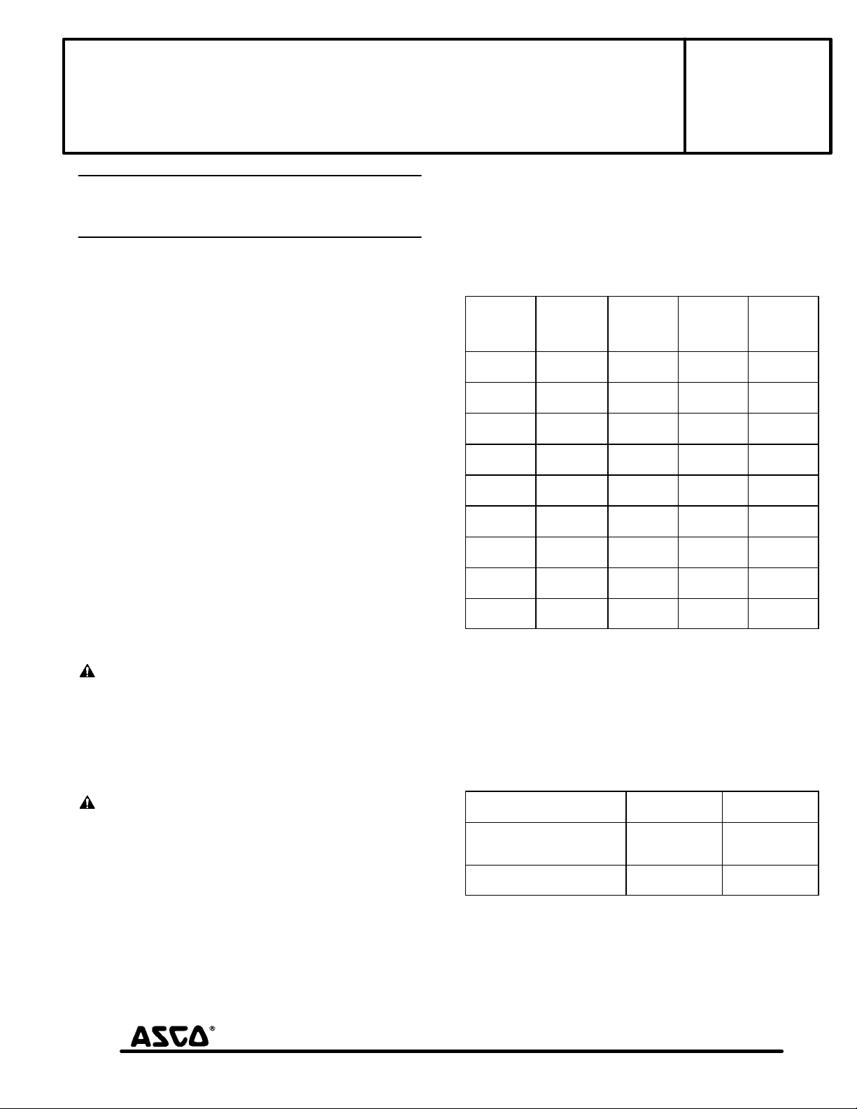
Temperature Limitations
For maximum valve ambient and fluid temperatures, refer to charts
below. Check catalog number, coil prefix, suffix, and watt rating on
nameplate to determine the maximum temperatures.
Catalog
Wattage
6, 10.5,
12.4
6,10.5
12.4
6,10.5,
12.4
9,10.7
9.7
11.2
16.7
17.1
17.1
Number
Coil
Prefix
none,ĂDA or
S
DF, FT
or SF
HT H 140 180
none, DP or
SP
none, FT or
HT
none, FT or
HT
none, DP or
SP
none, KP
SP or SD
HB, KB SS
or SV
Catalog Nos.8262B200 and 8262 C200 AC construction only and
Catalog Nos.8262B214 and 8262 D200 AC and DC construction are
limited to 140F fluid temperature.
Valves with Suffix V or W that are designed for AC service and norĆ
mally closed operation are for use with No. 2 and 4 fuel oil service.
These valves have the same maximum temperatures per the above
table except Suffix W valves are limited to a maximum fluid temperaĆ
ture of 140F.
Listed below are valves with Suffix V in the catalog number that are
acceptable for higher temperatures.
Catalog Number
Coil Prefix
FT8262, HB8262
FT8263, HB8263
8262G, 8263G
HT or HB 8262G
HT or HB 8263G
*The only exception is the 8262G and 8263G series (Class F coil) at 50
Hertz rated 11.1 and 17.1 watts are limited to 210F fluid temperature.
Positioning
This valve is designed to perform properly when mounted in any posiĆ
tion. However, for optimum life and performance, the solenoid
should be mounted vertically and upright to reduce the possibility of
foreign matter accumulating in the solenoid base sub-assembly area.
SERIES
8262
8263
Form No.V5256R9
Coil
Class
A 77 180
F 125 180
F 77 180
A, F
or H
A, F
or H
F 77 200
F 125 180
H 140 180
Max. Ambient
Temp.F
Max.
Ambient
Temp. F
77 120
77 150
Max. Fluid
Temp.F
125 250*
140 250
Max.
Fluid
Temp. F
MM All Rights Reserved.
50 Hanover Road, Florham Park, New Jersey 07932 www.ascovalve.com
Printed in U.S.A.
Page 1 of 4
Page 2
Valves with suffix P" in the catalog number must be mounted with
the solenoid vertical and upright.
Mounting
Refer to Figure 2 for mounting dimensions.
Piping
Connect piping or tubing to valve according to markings on valve
body. Inlet port will either be marked I" or IN". Outlet port will be
marked 2" or OUT". Wipe the pipe threads clean of cutting oils.
Apply pipe compound sparingly to male pipe threads only. If applied
to valve threads, the compound may enter the valve and cause operaĆ
tional difficulty. Avoid pipe strain by properly supporting and alignĆ
ing piping. When tightening the pipe, do not use valve or solenoid as
a lever. Locate wrenches applied to valve body or piping as close as
possible to connection point.
IMPORTANT: To protect the solenoid valve, install a strainer or filĆ
ter suitable for the service involved, in the inlet side as close to the
valve as possible. Clean periodically depending on service condiĆ
tions. See ASCO Series 8600, 8601 and 8602 for strainers.
MAINTENANCE
WARNING: To preventĂ the possibility of death,
serious injury or property damage, turn off electrical
power, depressurize valve, and vent fluid to a safe area
before servicing the valve.
NOTE: It is not necessary to remove the valve from the pipeline for
repairs.
Cleaning
All solenoid valves should be cleaned periodically. The time between
cleanings will vary depending on the medium and service conditions.
In general, if the voltage to the coil is correct,sluggish valve operation,
excessive noise or leakage will indicate that cleaning is required. In
the extreme case, faulty valve operation will occur and the valve may
fail to open or close. Clean strainer or filter when cleaning the valve.
Preventive Maintenance
Keep the medium flowing through the valve as free from dirt and
foreign material as possible.
While in service, the valve should be operated at least once a
month to insure proper opening and closing.
Depending on the medium and service conditions, periodic
inspection of internal valve parts for damage or excessive wear is
recommended. Thoroughly clean all parts. If parts are worn or
damaged, install a complete ASCO Rebuild Kit.
Causes of Improper Operation
Incorrect Pressure: Check valve pressure. Pressure to valve must
be within range specified on nameplate.
Excessive Leakage: Disassemble valve (see Maintenance) and
clean all parts. If parts are worn or damaged, install a complete
ASCO Rebuild Kit.
Valve Disassembly
1. Disassemble valve using exploded views for identification of parts.
2. Remove solenoid, see separate instructions.
3. Unscrew solenoid base sub-assembly or valve bonnet with
special wrench adapter supplied in ASCO Rebuild Kit. For
wrench adapter only, order No. K218948. Remove core
assembly, core spring, and solenoid base gasket from valve
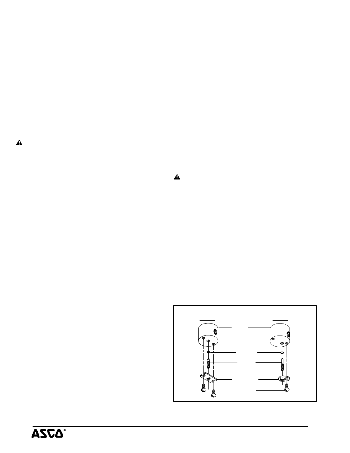
body. For normal maintenance on Series 8263 valves it is not
necessary to remove valve seat. See Figure 1 for metering or
manual operator constructions.
4. For normally open construction (Figure 3) remove end cap, or
manual operator, (not shown) end cap gasket, disc holder
spring, and disc holder assembly.
5. All parts are now accessible to clean or replace. If parts are worn
or damaged, install a complete ASCO Rebuild Kit.
Valve Reassembly
1. Use exploded views for identification, orientation and placement
of parts.
2. Lubricate all gaskets with DOW CORNING 111 Compound
lubricant or an equivalent high-grade silicone grease.
3. For normally open construction (Figure 3), install disc holder
assembly, disc holder spring, end cap gasket and end cap or
manual operator. For valves with 1/8 NPT, torque end cap or
manual operator to 90ñ 10 in-lbs [10,2 ± 1,1 Nm]. For all othĆ
er valves torque end cap or manual operator to 175 ± 25 in-lbs
[19,8 ± 2,8 Nm].
4. For Series 8263 apply a small amount of LOCTITE PST pipe
sealant to threads of valve seat (if removed). Follow manufacĆ
turers instructions for application of pipe sealant. Then install
valve seat and torque to 75 ± Ă10 in-lbs [8,5 ± 1,1 Nm].
5. Replace solenoid base gasket, core assembly with core spring
and solenoid base sub-assembly or plugnut/core tube sub-asĆ
sembly and valve bonnet. Note: For core assemblies with interĆ
nal type core springs, install wide end of core spring in core asĆ
sembly first, closed end of core springĂ protrudes from top of
core assembly.
6. For 1/8 NPT valve constructions, Torque valve bonnet to 90 ± Ă10
in-lbs [10,2 ± 1,1 Nm]. Torque solenoid base sub-assembly to
175 ± 25 in-lbs [19,8 ± 2,8 Nm].
7. Install solenoid, see separate solenoid instructions. Then make
electrical hookup to solenoid.
WARNING: To prevent theĂ possibility of death,
serious injury or property damage, check valve for
proper operation before returning to service. Also perĆ
form internal seat and external leakage tests with a
nonhazardous, noncombustible fluid.
8. Restore line pressure and electrical power supply to valve.
9. After maintenance is completed, operate the valve a few times
to be sure of proper operation. A metallic click signifies the soĆ
lenoid is operating.
ORDERING INFORMATION
FOR ASCO REBUILD KITS
Parts marked with an asterisk (*) in the exploded view are supplied in
Rebuild Kits. When Ordering Rebuild Kits for ASCO valves, order
the Rebuild Kit number stamped on the valve nameplate. If the numĆ
ber of the kit is not visible, order by indicating the number of kits reĆ
quired, and the Catalog Number and Serial Number of the valve(s)
for which they are intended.
Metering
Device
body
(1/8 NPT only)
O-ring
stem
retainer
screw
Figure 1. Metering and manual operator constructions.
Manual
Operator
Page 2 of 4 Form No.V5256R9
50 Hanover Road, Florham Park, New Jersey 07932 www.ascovalve.com
Page 3

Torque Chart
Bonnet wrench supplied in ASCO Rebuild Kits.
For bonnet wrench only order No. K218948.
Part Name
Torque value
Inch-Pounds Newton-Meters
Torque value
valve bonnet
bonnet gasket
plugnut/core tube
sub-assembly
core spring
(see note)
core assembly
body gasket
valve body
(1/8 NPT brass or
stainless steel)
mounting bracket
(stainless steel
construction only)
(see note)
valve body
(1/4 NPT
brass)
solenoid base
sub-assembly
valve bonnet
valve seat
+_+_
175 25 19,8 2,8
+_
90 10
+_+_
75 10 8,5 1,1
solenoid base
sub-assembly
core assembly
core spring
body gasket
valve body
(1/4 NPT
stainless steel)
mounting bracket
+_
10,2 1,1
(1/8 NPT brass)
Series 8262
Indicates Parts Supplied
in ASCO Rebuild Kits.
solenoid base
sub-assembly
(see note)
core assembly
body gasket
valve seat
valve body
(brass or
stainless steel)
Series 8263
Note:
Wide end of core spring in core first,
closed end protrudes from top of core.
Figure 2. Series 8262 and 8263, normally closed construction.
50 Hanover Road, Florham Park, New Jersey 07932 www.ascovalve.com
Page 3 of 4Form No.V5256R9
Page 4

Disassembly and Reassembly of Stem /Lever Type Manual
Operator (Refer to Figure 3)
NOTE: There are two stem/lever manual operator constructions.
They are identified by the location of the core spring as internal or
external spring construction.
1. Unscrew solenoid base sub-assembly from manual operator
body.
2. Unscrew manual operator body from valve body. Then remove
body gasket and stem retainer.
3. Slip stem/spacer sub-assembly with stem gasket from manual
operator body. Remove core assembly with core spring from
center of manual operator body.
4. All parts are now accessible for cleaning or replacement.
Lubricate gaskets per Valve Reassembly step 2.
5. Position core assembly with core spring into base of manual
operator body. Then install stem/spacer sub-assembly into
manual operator body to engage with core assembly.
6. Reinstall stem retainer on body and stem/spacer sub-assembly.
IMPORTANT: The spacer on the stem/spacer sub-assembly must
be inside of the stem retainer for internal spring construction and
outside the stem retainer for external spring construction.
7. Replace body gasket and install manual operator assembly in
valve body. Torque manual operator body to 175 ± 25 in-lbs
[19,8 ± 2,8 Nm].
8. Replace solenoid base gasket and solenoid base sub-assembly.
Torque solenoid base sub-assembly to 175 ± 25 in-lbs [19,8
± 2,8 Nm].
9. Check manual operator for proper operation. Turn stem clockĆ
wise and counterclockwise; stem should turn freely without
binding.
External Spring
Construction
solenoid base
manual
operator
body
stem
gasket
stem/spacer
sub-assembly
core assembly
body gasket
valve body
Indicates Parts Supplied
In ASCO Rebuild Kits
Note:
Wide end of core spring in core first, closed
end protrudes from top of core.
Spacer location for
external spring
construction
sub-assembly
solenoid base
gasket
stem gasket
stem retainer
core spring
External
spacer
stem retainer
Internal Spring
Construction
Internal
core spring
(see note)
Spacer location for
internal spring
construction
spacer
Important: Spacer must be inside of stem retainer
for internal spring construction and outside of stem
retainer for external spring construction.
solenoid base
sub-assembly
mounting bracket
(optional feature)
4 positions
2 self-tapping
screws provided
(see note 4)
valve bonnet
bonnet gasket
plugnut/core tube
sub-assembly
core spring
(see note 3)
core assembly
body gasket
valve body
(see note 2)
(Port 3 plugged)
disc holder assembly
disc
disc spring
mounting bracket
optional feature
(see note 1)
1/8 NPT-Stainless Steel
core spring
(see note 3)
core assembly
body gasket
valve body
(see note 2)
(Port 3 plugged)
disc holder assembly
disc spring
body gasket
end cap
Notes:
1.
For mounting, a flat surface must be provided
across the entire length of the bracket. The
valve body becomes secure to bracket when
bracket is tightened into position.
2.
Body inverted for in-line piping. Inverted 1 is
valve inlet and inverted 2 is valve outlet.
3.
Wide end of core spring in core first, closed
end protrudes from top of core.
4.
Bonnet wrench supplied in ASCO Rebuild Kit.
For bonnet wrench only order No. K218948.
body gasket
end cap
1/4 NPT-Brass
Indicates Parts Supplied
In ASCO Rebuild Kits
Figure 3. Stem/lever type manual operators Figure 4. Series 8262, normally open construction.
Page 4 of 4 Form No.V5256R9
50 Hanover Road, Florham Park, New Jersey 07932 www.ascovalve.com
 Loading...