

Page 1

Model “400” OVENPAK
®
Gas Burner Page 2105
Design and Application Details
OVENPAK® Burners are nozzle-mixing gas burners
for many industrial direct-fired applications where
clean combustion and high turndown are required.
They are simple and versatile for use on a variety of
heating applications.
The Model “400” OVENPAK® Burner (shown at
right) includes a combustion air blower with nonsparking paddle wheel-type impeller, pilot, spark
ignitor, stainless steel discharge sleeve, mixing cone,
self-contained internal air and gas proportioning
valves, and provision for your flame safeguard
sensor.
Right: Model 415 OVENPAK® Gas Burner with optional:
• combustion air filter
• connecting base and linkage assembly
• electrical control motor (by others)
Cross sectional view of a Model “400” OVENPAK® Gas
Burner
Principle of operation (illustrated at left)
The OVENPAK® Burner is designed for industrial
air heating applications. It is available in two basic
versions: 1) packaged with integral combustion air
blower, or 2) for use with an external blower. Both
versions include a gas and air valve, internally linked
together to control the gas-air ratio over the full
operating range. The gas flows through the nozzle,
then along the inside of the burner cone where
combustion air is progressively and tangentially mixed
with the gas. This produces a very wide turndown
range and a highly stable flame under a variety of
operating conditions.
10/92
Page 2

Page 2106 Model “400” OVENPAK® Gas Burners
Design and Application Details
Model “EB” (external blower) OVENPAK® Burners
(shown at right), like all OVENPAK® Burner assemblies, are designed to deliver heat through a patented
mixing cone and stainless steel sleeve.
Flanged burner body design on all OVENPAK
Burner assemblies simplifies mounting and installation on your application. Burner can be installed in
any position that does not conflict with your control
motor or flame detector requirements.
Minimal torque requirements permit use of most
electric or air operators in conjunction with the optional (Maxon supplied) connecting base and linkage
assemblies.
Model “EB-MA” OVENPAK® Burner with discharge sleeve
and optional manual gas control
®
view into
cone of
EB version
Model EB-3 OVENPAK® Burner arranged for external
blower source with connecting base and linkage assembly
to adapt customer's automatic control motor
“400-MA” and “EB-MA” versions
Model “400-MA” versions include a combustion air
blower in your choice of the voltages shown on page
2107, but provide constant combustion air volumes.
They differ from “standard” versions by use of a
slotted adjustable air butterfly locking device as
shown in photo at left. Internally, the linkage normally
cross-connecting air and gas butterflies is omitted.
In normal operation, the air butterfly is set to the
desired air differential pressure, and the fuel only is
throttled by a separate control valve. Maximum
capacities match those cataloged for “standard”
burners of equivalent size. Minimum capacities with
full air flow will be higher than those of “standard”
burner.
“EB-MRV” versions (photo at right)
“EB-MRV” versions of OVENPAK® Burners permit
air/fuel ratio control via a Maxon MICRO-RATIO®
control valve throughout the firing range. They differ
from standard “EB” burners in that internal gas and air
butterflies and the related shafts and linkages are
omitted.
In normal operation, air and fuel will be proportioned by an external Maxon MICRO-RATIO® Control
valve.
Maximum capacities match those cataloged for
“EB” burners of equivalent size and differential air
pressure. Minimum capacity and air differential
pressure will vary with your application.
Model “EB-MRV” OVENPAK® Burner with optional 12"
discharge sleeve
Page 3
®
Gas Burners
Page 2107Model “400” OVENPAK
Capacities and Specifications – 60 Hertz
Standard Model “400” OVENPAK® Burner in-
cludes a combustion air blower with motor.
Maximum capacity of Model “400” OVENPAK
®
Burner is affected by the static pressure within the
combustion chamber. Data shown assumes firing in
the open, or into an airstream with enough oxygen to
complete the combustion process. If burner is fired into
an oxygen-starved chamber or airstream, capacities
may be reduced as much as 25-30%. Do not attempt
to operate beyond the duct static pressure range
shown. For higher back pressure applications, select
from Model “EB” or “EB-MRV” OVENPAK® Burner
options.
All gas pressures are differential pressures and
are measured at the gas pressure test connection on
the backplate of each OVENPAK
®
Burner. Differential
pressures shown are approximate.
–ataDgnitarepOdnaseiticapaC
ledoMrenruB504M704804M804M214M314514M224
rotoM
noitacificepS
D
U
C
T
mumixaM
seiticapaC
S
)rh/utBs'0001(
T
saGlarutaNhtiw
A
)cw"(serusserP
T
I
C
S
muminiM
seiticapaC
)rh/utBs'0001(
erusserp )cw"(telnirenrubot
riallitsni
:rewopesroH3/12/13/14/32/14/33/14/3
:rebmuNemarF8484846584658465
ot0.5-
cw"5.0-
cw"0±
cw"0.1+
cw"0.2+
cw"0.3+
cw"0.4+
cw"0.5+
tolipsulpniaM510273
ylnotoliP015102
laitnereffidsaglarutanderiuqeR
htgnelemalfetamixorppA
055
"8.2
005
"3.2
574
"1.2
054
"9.1
---
---
---------
--057
"5.2
007
"2.2
006
"6.1
015
"1.1
054
"9.0
0.35.31.45.42.52.42.7
.tf1ot2/1
elbaliavAsegatloVrotoMzH06
-802/511
06/1/032
XXX
XXX
toN
elbaliavA
2/1&3/1
1&4/3
rewopesroHepyT
3&2,2/1-1
yllatoT
desolcnE
yllatoT
desolcnE
yllatoT
desolcnE
M224hguorht504ledoM
088
"4.3
008
"8.2
067
"6.2
027
"3.2
---
---
ot1
.tf2/1-1
-------097
"7.2
057
"5.2
046
"8.1
055
"3.1
594
"1.1
574
"0.1
.tf1ot2/1.tf2/1-2ot1
0021
"8.2
0011
"4.2
529
"7.1
008
"3.1
057
"1.1
---
0031
"3.3
0911
"8.2
0011
"4.2
0001
"0.2
009
"6.1
008
"3.1
-802
06/3/064/032
XX
0561
"7.1
0051
"4.1
5241
"3.1
0531
"1.1
---
---
---
ot2/1-2
.tf2/1-3
06/3/575
--0512
"9.2
0002
"5.2
5271
"9.1
0161
"6.1
0051
"4.1
0241
"3.1
ot2/1-1
.tf2
5/93
Page 4

Page 2108 Model “400” OVENPAK® Gas Burners
Capacities and Specifications – 60 Hertz
–ataDgnitarepOdnaseiticapaC M784hguorht524ledoM
ledoMrenruB524M234534M244544M654M074M784
rotoM
noitacificepS
D
U
C
T
mumixaM
seiticapaC
S
)rh/utBs'0001(
T
saGlarutaNhtiw
A
)cw"(serusserP
T
I
C
S
muminiM
seiticapaC
)rh/utBs'0001(
erusserp )cw"(telnirenrubot
riallitsni
:rewopesroH4/34/34/311 2/1-123
:rebmuNemarF6565656565T341T541T281
ot0.5-
cw"5.0-
cw"0±
cw"0.1+
cw"0.2+
cw"0.3+
cw"0.4+
cw"0.5+
cw"0.6+
tolipsulpniaM0678011521051571
ylnotoliP535409501511711
laitnereffidsaglarutanderiuqeR
htgnelemalfetamixorppA
0572
"7.2
0052
"2.2
5732
"0.2
0522
"8.1
---
---
---
------------------
6.39.48.39.45.41.52.56.7
--0023
"6.3
0003
"2.3
0082
"8.2
0562
"5.2
0052
"2.2
0522
"8.1
.tf2/1-3ot2/1-2
0583
"2.2
0053
"8.1
5233
"6.1
0513
"4.1
---
---
---
ot2/1-3
.tf5
--0514
"5.2
0004
"4.2
0083
"1.2
0563
"9.1
0053
"8.1
0033
"6.1
.tf5ot4.tf6ot4.tf7ot5.tf8ot6.tf01ot8
5715
"4.3
0054
"6.2
0824
"3.2
5214
"2.2
---
---
---
0046
"6.3
0065
"8.2
0435
"5.2
0025
"4.2
0005
"2.2
0064
"9.1
0014
"5.1
0508
"7.3
0007
"8.2
0756
"5.2
0036
"3.2
0055
"7.1
0005
"4.1
0054
"2.1
0053
"7.0
06001
"6.4
0078
"4.3
0048
"2.3
0028
"0.3
0057
"5.2
0026
"7.1
0055
"4.1
0005
"1.1
Page 5
Page 2109Model “400” OVENPAK® Gas Burners
Capacities and Specifications – 50 Hertz
Standard Model “400” OVENPAK
®
Burner includes a combustion air blower
with motor.
Maximum capacity of Model “400”
OVENPAK
®
Burner is affected by the static
pressure within the combustion chamber.
Data shown assumes firing in the open, or
into an airstream with enough oxygen to
complete the combustion process. If burner
is fired into an oxygen-starved chamber or
airstream, capacities may be reduced as
much as 25-30%. Do not attempt to operate
beyond the duct static pressure range
shown. For higher back pressure applications, select from Model “EB” or “EB-MRV”
OVENPAK
®
Burner options.
All gas pressures are differential
pressures and are measured at the gas
pressure test connection on the backplate
of each OVENPAK® Burner. Differential
pressures shown are approximate.
-ataDgnitarepOdnaseiticapaC
ledoMrenruB504M704804M804M214M314514M224
rotoM
noitacificepS
D
U
C
T
mumixaM
seiticapaC
S
)rh/utBs'0001(
T
saGlarutaNhtiw
A
)cw"(serusserP
T
I
C
S
muminiM
seiticapaC
)rh/utBs'0001(
erusserp )cw"(telnirenrubot
riallitsni
:rewopesroH3/12/13/14/32/14/33/14/3
:rebmuNemarF8484846584658465
cw"0.5-
cw"0.3-
cw"0±
cw"0.1+
cw"0.2+
tolipsulpniaM5102510273
ylnotoliP015102
laitnereffidsaglarutanderiuqeR
htgnelemalfetamixorppA
064
"0.2
064
"0.2
514
"6.1
093
"4.1
---------------
2.23.20.36.25.31.49.26.5
elbaliavAsegatloVrotoMzH05
rewopesroHepyT05/1/002-09105/3/514-08305/3/005
2/1&3/1
1&4/3
3&2,2/1-1
yllatoT
desolcnE
yllatoT
desolcnE
yllatoT
desolcnE
XXX
XXX
XXX
)tsocartxetenelbissop(
M224hguorht504ledoM
---
--526
"7.1
585
"5.1
.tf1ot2/1
537
"4.2
537
"4.2
076
"0.2
036
"7.1
ot1
.tf2/1-1
---------
--------066
"9.1
526
"7.1
.tf1ot2/1.tf2ot1
0001
"0.2
029
"7.1
0801
"5.2
099
"4.2
029
"7.1
5731
"2.1
5731
"2.1
0521
"0.1
0911
"9.0
---
ot2/1-1
.tf2
---
--0081
"0.2
0761
"8.1
0441
"3.1
ot2
.tf2/1-2
8/00
Page 6

Page 2110 Model “400” OVENPAK® Gas Burners
Capacities and Specifications – 50 Hertz
-ataDgnitarepOdnaseiticapaC
ledoMrenruB524M234534M244544M654M074M784
rotoM
noitacificepS
D
U
C
T
mumixaM
seiticapaC
S
)rh/utBs'0001(
T
saGlarutaNhtiw
A
)cw"(serusserP
T
I
C
S
muminiM
seiticapaC
)rh/utBs'0001(
erusserp )cw"(telnirenrubot
riallitsni
:rewopesroH4/34/34/311 2/1-123
:rebmuNemarF6565656565T341T541T281
cw"0.5-
cw"0.3-
cw"0±
cw"0.1+
cw"0.2+
cw"0.3+
tolipsulpniaM0678011521051571
ylnotoliP535409501511711
laitnereffidsaglarutanderiuqeR
htgnelemalfetamixorppA
0032
"9.1
0032
"9.1
0902
"6.1
0791
"4.1
---------
---------------------
5.28.32.28.31.36.30.50.5
---
--0762
"5.2
0432
"0.2
.tf3ot2
0292
"3.1
0292
"3.1
0872
"1.1
---
ot3
.tf2/1-4
M784hguorht524ledoM
---
--0643
"8.1
0433
"6.1
0223
"5.1
ot2/1-3
.tf4
5234
"4.2
5234
"4.2
0673
"8.1
---
---
.tf5ot4.tf6ot5.tf8ot7
0535
"5.2
0535
"5.2
0764
"9.1
0544
"8.1
0434
"7.1
0076
"6.2
0076
"6.2
0585
"0.2
0055
"7.1
0525
"6.1
0048
"2.3
0048
"2.3
0527
"3.2
0507
"1.2
0586
"1.2
0526
"7.1
Page 7

®
Gas Burners
Capacities and Specifications
External Blower (EB) versions
Page 2111Model “400” OVENPAK
dnanoitsubmoC
riAgnilooC
deriuqer
1-BE
®
KAPNEVO
sesaeleRtaeH
)rh/utBs'0001(
renruB
saGlarutaN
laitnereffid
serusserp )cw"(
shtgneLemalF
dnanoitsubmoC
riAgnilooC
deriuqer
2-BE
®
KAPNEVO
sesaeleRtaeH
)rh/utBs'0001(
renruB
saGlarutaN
laitnereffid
serusserp )cw"(
shtgneLemalF
dnanoitsubmoC
riAgnilooC
deriuqer
3-BE
®
KAPNEVO
sesaeleRtaeH
)rh/utBs'0001(
renruB
saGlarutaN
laitnereffid
serusserp )cw"(
shtgneLemalF
)MFCS(emuloV051071091012042552072082
tolip&muminiM0606060606060606
ylnotoliP5454545454545454
telnirenrubtA1.24.31.51.66.73.82.90.01
riallitsnI eveelsegrahcsidfodnednoyeb"51ot"4
)MFCS(emuloV022052082013553573593514
tolip&muminiM0606060607075708
ylnotoliP5252525203035353
telnirenrubtA32.58.75.93.111.219.218.31
riallitsnI eveelsegrahcsidfodnednoyeb"03ot"21
)MFCS(emuloV053504554594575516056576
tolip&muminiM0959501511031041051551
ylnotoliP5454055556075757
telnirenrubtA1.46.50.73.80.115.219.314.51
riallitsnI eveelsegrahcsidfodnednoyebteef3ot2
)cw"(erusserPriAlaitnereffiD
345689 0111
yticapaCmumixaM
noitcennoctsetsagrenrubtA0.21.37.46.50.76.75.82.9
)cw"(erusserPriAlaitnereffiD
yticapaCmumixaM
noitcennoctsetsagrenrubtA5.22.43.67.72.98.95.012.11
)cw"(erusserPriAlaitnereffiD
yticapaCmumixaM
noitcennoctsetsagrenrubtA6.12.28.23.34.40.56.52.6
0640855170870780190690001
345689 0111
057089002103310541005105510061
345689 0111
02610091021202320762048200030513
12/92
dnanoitsubmoC
riAgnilooC
deriuqer
4-BE
®
KAPNEVO
sesaeleRtaeH
)rh/utBs'0001(
renruB
saGlarutaN
laitnereffid
serusserp )cw"(
shtgneLemalF
)MFCS(emuloV05553601757759805900010501
tolip&muminiM001511031041061071081091
ylnotoliP0404045405555506
telnirenrubtA5.27.39.48.54.71.88.80.01
riallitsnI eveelsegrahcsidfodnednoyebteef2/1-3ot2/1-2
)cw"(erusserPriAlaitnereffiD
345689 0111
yticapaCmumixaM
noitcennoctsetsagrenrubtA9.18.27.33.45.51.66.65.7
02320082032300530593051403340064
Page 8

Page 2112 Model “400” OVENPAK® Gas Burners
Capacities and Specifications
External Blower (EB) versions
dnanoitsubmoC
riAgnilooC
deriuqer
5-BE
®
KAPNEVO
sesaeleRtaeH
)rh/utBs'0001(
renruB
saGlarutaN
laitnereffid
serusserp )cw"(
shtgneLemalF
dnanoitsubmoC
riAgnilooC
deriuqer
6-BE
®
KAPNEVO
renruB
7-BE
®
KAPNEVO
renruB
sesaeleRtaeH
)rh/utBs'0001(
saGlarutaN
laitnereffid
serusserp )cw"(
shtgneLemalF
dnanoitsubmoC
riAgnilooC
deriuqer
sesaeleRtaeH
)rh/utBs'0001(
saGlarutaN
laitnereffid
serusserp )cw"(
shtgneLemalF
)MFCS(emuloV5660770680490801051101210721
tolip&muminiM551081002022552072582003
ylnotoliP5203535304540505
telnirenrubtA2.21.30.49.46.65.73.81.9
riallitsnI eveelsegrahcsidfodnednoyebteef5ot3
)MFCS(emuloV5790621095107810522093204620672
tolip&muminiM533093094575596537518058
ylnotoliP001001001511041541561071
telnirenrubtA8.26.53.117.518.226.523.131.43
riallitsnI
)MFCS(emuloV5790621095107810522093204620672
tolip&muminiM533093094575596537518058
ylnotoliP001001001511041541561071
telnirenrubtA8.16.33.71.018.416.612.021.22
riallitsnI
)cw"(erusserPriAlaitnereffiD
345689 0111
yticapaCmumixaM
noitcennoctsetsagrenrubtA3.18.13.29.29.34.48.43.5
)cw"(erusserPriAlaitnereffiD
yticapaCmumixaM
noitcennoctsetsagrenrubtA0.20.41.82.113.613.813.223.42
)cw"(erusserPriAlaitnereffiD
yticapaCmumixaM
noitcennoctsetsagrenrubtA0.10.21.46.52.82.92.112.21
04920053089302440315054504750006
358 1161812242
0174007600590021100531003410085100561
fodnednoyebteef8ot3
eveelsegrahcsid
358 1161812242
0174007600590021100531003410085100561
fodnednoyebteef8ot3
eveelsegrahcsid
fodnednoyebteef21ot8
eveelsegrahcsid
fodnednoyebteef21ot8
eveelsegrahcsid
Page 9

®
Gas Burners
Accessory Options
Air filter assemblies and silencers
Page 2113Model “400” OVENPAK
Air filter assemblies help to trap airborne particu-
late matter. They are offered with washable replaceable
filter elements or with permanent metallic elements (as
shown in photograph above). Filters mount onto
OVENPAK
®
Burner's blower housing (or silencer
housing of burners so equipped) and surround the
blower motor and combustion air inlet.
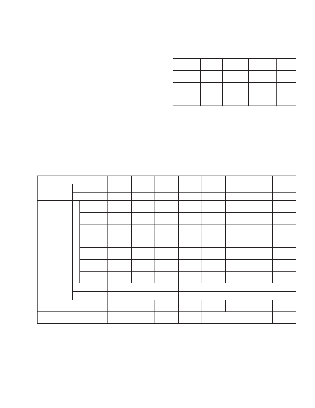
dB(A) sound levels
from actual tests conducted at full-rated 60 Hz
capacity are shown in table
at right. Measurement point
is shown in sketch below.
(Meter was set to A-scale,
slow response.)
Operation on 50 Hz
power results in lower
rotational speed of blower,
and so reduces air output,
capacity, and resulting
noise levels. 50 Hz noise
levels should not exceed
the above data measured
on 60 Hz operation.
Burner
Model
405
407M
408M
408
412M
413M
415
422M
425
432M
435
442M
445
456M
470M
487M
Sound Level dB(A)
Standard
Burner
84
83
84
87
81
82
89
88
89
88
87
89
89
90
92
94
with
Silencer
75
77
75
78
73
72
77
79
78
80
78
80
81
83
83
85
Filter silencers help reduce noise levels. They
mount onto OVENPAK® Burner's blower housing and
enclose the blower motor and combustion air inlet (as
shown in above photograph). They can be furnished in
conjunction with a permanent or replaceable filter
element assembly described above.
6/96
Page 10

Page 2114 Model “400” OVENPAK® Gas Burners
Accessory Options
Universal Joint Arrangements (for all
versions except EB-MRV) allow control of as many as
5 burners by a single control motor. Torque requirement is 10 in-lbs for EACH burner driven. Primary
burner should drive no more than 2 Secondary burners
to either side of itself.
Miniature universal joints simplify burner alignment.
Aluminum connecting rod can be cut to fit actual
burner spacing. (
burner centerlines is 21" – 33" for 422M and smaller,
23.5" – 36" for larger burners.)
1. Primary and secondary burners
2. Any other accessories desired
3. Required quantity of Universal Joint Assemblies
Allowable distance between adjacent
To order, specify:
Auxiliary Switches
Maxon offers 4 types, all cam-actuated by the
burner main operating shaft. (If Universal Joint Arrangements are used, switch must mount on furthest
left burner.) Field installation MAY require burner
modification per instructions provided in Product
Information Sheet 2000-7/8.
Low Fire Start Switch Assembly (SPDT) opens
the circuit when burner leaves minimum position. Also
available in Weatherproof and Hazardous Location/
Weatherproof versions.
High and Low Fire Position Switch Assembly
includes 2 SPDT switches. One switch may be fieldset to activate at high fire position, while other is set to
activate at low fire position. Switch assemblies are
also available in a weatherproof version.
Manual Handle Kit permits setting and locking
air and fuel valves at a constant firing rate. See photo
below.
Low Fire Start Switch shown
Discharge Sleeve Mounting Gaskets
Standard discharge sleeve gasket provides
adequate sealing in most applications.
High Back Pressure Gasket Kit includes 2 additional gaskets to provide sealing against back pressures as shown in sketch below.
Standard
Arrangement
High Back Pressure Kit
With
Page 11

Model “400” OVENPAK® Gas Burners
Accessory Options
Page 2115
Hi/Lo Control Motor Sets for high or low firing.
Optional set includes 2-position unidirectional 11second 120v 50/60 Hz motor and connecting base with
mounting linkage. See table below for dimensions
which differ from standard burner.
sehcnInisnoisnemiD
2,1-BEM314-504
3-BEM224-514
5,4-BEM244ot524
7,6-BEM784-544
ledoMrenruB
PRT
52.0136.7157.7
91.0165.7157.7
96.1160.9157.8
96.6160.4257.8
Discharge Sleeves are available in 3 versions:
– Standard sleeve is 8" long, made of #310 SS, and
is suitable for downstream temperatures up to
1000°F (538°C).
– For higher velocities, specify 12" long sleeve made
of #310 SS for downstream temperatures up to
1000°F (538°C).
– For higher downstream temperatures between
1000°F (538°C) and 1500°F (816°C), specify 8" long,
#RA 330 SS sleeve.
9/94
Page 12

Page 2116 Model “400” OVENPAK® Gas Burners
Dimensions (in Inches)
Model “400” and “400-MA” OVENPAK® Burners
NOTE: Use of auxiliary switches will add to dimension D.
ledoMA*BCDEF GHJK LMN CCDDEEFFGGHHJJKK
504
M704
804
57.31
M804
M214
M314
514
57.44/1-196.718.852.0173.0152.873.0144.4
M224
524
M234
534
M244
544
M654
M074
M784
2/1-1
57.5
2
18.683.4188.6113.9126.415.652.2157.4196.673.5
3 57.7197.719118.6249.52
44.5
60.626.8
TPNtelnisagleufniaM*
26.678.803.01
60.0188.1196.4105.2144.552.015.2126.5
44.8
91.31
73.4
13.644.826.3
52.0
73.0
18.873.114166.3
52.5178.518196.496.9196.1226.81
18.873.114166.321.9118.7173.4160.71
52.5178.518196.4
18.873.1141
52.5178.51
21.2144.4149.3
52.5178.5118.252.1265.3226.92
21.2144.4149.35.0252.0257.91
52.5178.51
95.313.71
81
18.252.1265.32
42
13.71
13.71
21.91
52.81
5.22
18.7173.4160.71
96.9196.1226.81
57.7173.4160.71
65.9196.1226.81
5.0252.0257.91
525.32
26.92
Pipe threads on this page conform to NPT (ANSI Standard B2.1)
Page 13

Dimensions (in Inches)
Model EB, EB-MA, and EB-MRV OVENPAK
Page 2117Model “400” OVENPAK® Gas Burners
®
Burners
NOTE: Use of auxiliary switches will add to dimension D.
ledoMABCDEFGHJKLMNUVWXYAABB
1-BE
57.3
2-BE
3-BE
4-BE
5-BE
6-BE
7-BE
4/1-144.5
57.496.773.0152.873.0144.483.5
57.52
18.63 83.4188.6113.9126.415.652.2157.4196.626.921.11
60.626.8
26.6
78.813.0191.31
60.0188.1196.415.2144.552.015.2126.5
44.8
73.4
13.644.826.3
52.052.726.873.644.044.5
52.926.0178.8
73.0
65.0
-7.11
5
Refractory Lined Discharge Sleeve
.562 dia.
8 holes
D dia.
22.5˚
45˚
A
BC
renruB
eziS
M314-504
2BE,1BE
M224,514
3BE
M244-524
5BE,4BE
M784-544
7BE,6BE
ABC .aidD
83.831.0160.4136.21
83.80.2149.515.41
83.860.410.8135.61
83.860.610.0235.81
44.5
4
57.766
52.015.88
10/03
Pipe threads on this page conform to NPT (ANSI Standard B2.1)
Page 14

Page 2118 Model “400” OVENPAK® Gas Burners
Accessory Dimensions (in Inches)
Filter with silencer for Model “400” OVENPAK® Burner
ledoMJJLLMMNNPPRRSSTTUU
504
M704
804
M804
M214
M314
514
M224
524
M234
534
M244
544
M654
M074
M784
4.414.21
7.121.519.128.77.424.131.53
4.414.213.914.012.329.926.33
7.121.519.128.77.424.131.53
4.414.213.914.01
7.121.51
2.025.413.8429.526.233.63
6.321.81229.428.019.429.135.833.24
52.025.41614.123.8429.526.233.63
6.32
5.32 6.82
9.522.02422.928.216.929.337.243.44
1.81229.428.01
61
3.914.01
9.12
2.329.926.33
2.32
8.77.424.131.53
1.32
9.42
2.329.926.33
9.135.833.24
Pipe threads on this page conform to NPT (ANSI Standard B2.1)
Page 15

Component Identification
Page 2119Model “400” OVENPAK® Gas Burners
Suggested spare parts
– Spark Ignitor – Discharge Sleeve and Gasket
– Flame Rod, if used – Motor
– Filter Elements, if used – Impeller
– Mixing Cone – Gas/Air Valve Linkage Kit
To order parts for an existing OVENPAK® Burner assembly, list:
1. Name(s) of part(s) from above illustration
2. Quantity of each required
3. OVENPAK® Burner nameplate information:
• size and model number of burner
• assembly number
• date of manufacture
• if available, serial number of Maxon fuel shut-off valve in-line to OVENPAK
Burner (This serial number is on Maxon valve's nameplate.)
9/03
Nameplate
®
Page 16

Page 2120 Model “400” OVENPAK® Gas Burners
Suggested Maintenance/Inspection Procedures
Discharge sleeve and cone alignment
Centering of the mixing cone provides a small
annular opening for the flow of some cooling combustion air along the discharge sleeve wall. We SUGGEST
periodic inspection from the discharge side of the
burner to assure that this alignment is maintained.
Caution: Tightening can lead to cone distortion
and greatly reduce cone and discharge sleeve
life. Cone should be free to move and allow for
thermal expansion.
If re-adjustment is necessary, back out the four lock
nuts and re-center mixing cone with adjusting screws
handtight. Back each screw out one-half turn before relocking. This allows for thermal expansion as cone
gets hot.
Filters should be inspected regularly and cleaned,
using a vacuum to remove loose/dry accumulations,
then washing and/or degreasing as appropriate for the
filter type used.
To replace flame rod or spark ignitor:
1. Check Table 1 at right for dimension “Y” and cut tip
to length shown.
2. Insert 1/2" NPT collar into burner and snug into
position.
3. Insert insulator through collar into burner.
4. Check table for dimension “X”, position accordingly,
and tighten locking bushing until insulator is held
firmly.
WARNING: Over-tightening locking bushing may
damage insulator.
NOTE: A full-wave 6000 volt spark ignition transformer
is suggested for use with Maxon burner equipment.
Flame Rod
NOTE: 1/2" x 1" adapter bushing supplied by others
Table 1: Flame rod and spark ignitor dimensions
for all Model “400” OVENPAK® Burners
manufactured after 1/1/91 ①
rotingIkrapS
ledoMrenruB
XYXYZ
504
M704
1-BE
2-BE
3-BE
4-BE
5-BE
6-BE
7-BE
M804
804
M214
M314
514
M224
524
M234
534
M244
544
M654
M074
M784
3.14.
5.14.
2.14.8.8.015.3
3.14.4.8.219.2
snoisnemiD
4.69.2
doRemalF
snoisnemiD
①
Manufactured date is stamped on metal nameplate
of Model “400” OVENPAK® Burner. For specifics
relative to units manufactured prior to 1/1/91, see
Product Information Sheet 2100-3.
Page 17

Page 2121Model “400” OVENPAK® Gas Burners
Maxon Pre-Assembled P acka ge
Model “400” OVENP AK® Gas Burner System
Save time and reduce your installation costs with a
completely assembled and pre-wired burner and pipe
train “package”.
All system components have been carefully selected to match the high performance characteristics of
the Model “400” OVENPAK® Gas Burner.
The compact design of this “packaged system”
makes mounting to your duct fast and easy. Connect
to the gas line and bring in electricity. It's wired and
piped, ready to go.
425 OVENPAK
package system
installed and
mounted onto a
Maxon
pre-fabricated
heater/duct section
All pre-assembled package systems include a
Model “400” OVENPAK® Burner and pipe train. The
pipe trains are available with “Block and Bleed” arrangement options only.
Additional application flexibility is provided with five
different sized systems, all with 40:1 turndown
capacity ranges.
Packaged OVENPAK® Burner systems may also be
mounted in a pre-fabricated combustion heater/duct
section by Maxon. This option is value-engineered to
give you the most for your dollar spent.
®
6/03
Page 18

Page 2122 Model “400” OVENPAK
Design / Application Summary
Five Model "400" OVENPAK® pre-assembled package options:
®
KAPNEVO
rotoMrewolBdesolcnEyllatoT
yticapaCmumixaM )rh/utB(
yticapaCmuminiM tolipsulpniam)rh/utB(
erusserpsaglarutanmuminiM telniniartepiptaderiuqer
ezisniartepiptelnI TPN
>ledoMrenruB504804514524534
rewopesroH
rebmuNemarF
000,005000,008000,005,1000,005,2000,005,3
000,51000,02000,73000,06000,78
snoisnemidepolevnellarevoetamixorppA
3/14/3
8465
cw"6cw"01cw"9cw"41
"52.1"5.1
®
Gas Burners
ediw"42xhgih"04xgnol"24
Pre-assembled pipe train “package”
includes the following components:
– Burner gas shut-off cock
– Main inlet gas shut-off cock
– Pilot gas train consisting of:
• Pilot gas shut-off cock
• Pilot gas pressure regulator (maximum 1 PSIG
natural gas inlet pressure)
• Pilot gas solenoid valve, 115/60VAC
– Main gas pressure regulator (maximum 1 PSIG
natural gas inlet pressure)
– Combustion air pressure switch, automatic reset,
NEMA 1, 115/60VAC
– Combination high and low gas pressure switch,
manual reset, NEMA 1, 115/60VAC
– Spark ignition transformer, 6000 volts, NEMA 1, 115/
60VAC
– NEMA type 12 and 13 junction box with terminal
wiring strip
– Normally open vent solenoid valve, 115/60VAC
A complete packaged system also includes:
• Maxon Model “400” OVENPAK® Burner assembly
– Connecting base and linkage assembly to adapt
customer-supplied automatic control motor
(optional)
– Low fire start switch (mounted to OVENPAK
Burner)
– Air filter assembly
• Maxon main gas shut-off valve, position “L”, 115/
60VAC
• Maxon main gas “blocking” shut-off valve, position
“L”, 115/60VAC00000000
®
Factory pre-wiring includes the following
components for 115 volts 60 hertz AC:
– Low fire start switch
– Combustion air pressure switch
– Combination high and low gas pressure switch
– Pilot gas solenoid valve
– Normally-open vent solenoid valve (when used)
– Spark ignition transformer
– Maxon “main” and/or “blocking” gas shut-off valve(s)
– NEMA type 12 and 13 junction box with terminal
wiring strip
Field wiring is required:
– To the packaged system's junction box wiring strip
– To the Model “400” OVENPAK® Burner's combustion
air blower motor
– Between your flame safeguard relay and the
OVENPAK® Burner's flame sensor
NOTE: A flame rod may be furnished by Maxon; UV
detector is a part of the control package when
supplied by Maxon or may be supplied by others.
– Other field wiring connections may be required if your
control circuit includes high/low temperature limits,
automatic temperature controller, and/or other
miscellaneous safety limit switches.
Page 19

®
Gas Burners
Page 2123Model “400” OVENPAK
Maxon Packaged Heater/Duct Sections
Reduce your fabrication time with a complete
combustion heater/duct including the prewired and
prepiped Model “400” OVENPAK® Burner system
package.
Easy installation is provided by flanged duct
connection joints. Burner is mounted to a .312" mild
steel wall, lined with 6" thick fiber insulation. The other
16 gauge aluminized steel heater/duct walls are ready
for your insulation.
Application flexibility is offered by three sizes of
ducts. All sizes can be fabricated to have return/inlet
opening at any 90° increment position (viewing from
the back of the OVENPAK
®
Burner). Continuous welds
on all joint seals permit duct section installation on
pressure-side or suction-side applications.
6/03
snoisnemidnoitcestcudetamixorppA )sehcnini(
ledoMAB)edisni( CD)edisni( EFGHJ)edisni( K
804-504
514
534-524
2142501638426.2126.625.773
5103621240626.4126.235.984
8163861842726.8126.835.1185
Page 20

Page 2124 Model “400” OVENPAK
®
Gas Burners
Maxon Packaged Heater/Duct Sections
Design and Application Details
Maximum discharge temperature 600°F (316°C)
Duct static pressures may range between +2" wc and -5" wc
Optimum design parameters permit up to 3000 feet per minute air velocity through return/inlet duct.
semulovriaegrahcsidmumixamdednemmoceR
®
KAPNEVO"004"ledoM
To select your packaged system, specify:
1. Quantity ________
renruB504804514524534
emulovriaegrahcsidmumixaM MFCSni
00050057000,21
2. Model “400” OVENPAK
– Arranged for UV detector, or with flame rod
– Furnished with blower motor for ___________ AC
– With low fire start switch _________ , General Purpose, 115/60 AC
– With combustion air filter assembly ____________ (optional)
– With connecting base and linkage assembly ____________ to adapt customer's automatic electric
control motor. Specify/select which one of these electric operators will be used:
– Barber-Colman #EA51–58, also with prefix MC, MP or MF
– Honeywell #M644, #M744, #M941, or #M944
– Penn/Johnson #M-80 or #M81
3. Arranged into pre-assembled and wired pipe train package, 115/60VAC,
– With Block and Bleed arrangement assembly ______________.
4. With _______ 1-1/4" or 1-1/2" Maxon Series __________ Automatic Reset, Manual Reset
Shut-Off Valve(s), for natural gas, in top assembly position “L” for 115/60VAC
– With electrical terminal block (option)
– With 6 second, or 2.5 second opening time (automatic reset valve(s) only)
– With ______________ auxiliary signal switch(es) (optional)
NOTE: Specify which switch(es) go in main valve and which switch(es) in blocking valve, if different.
®
Gas Burner Assembly _________, for natural gas
5. With heater/duct section assembly ____________ (optional)
with return/inlet duct positioned on top, right, bottom, or left
Page 21

®
Gas Burners
Page 2125Model “200” OVENPAK
Model “200” OVENPAK
®
Burners
Model “200” OVENPAK® Gas Burners
provide a broad range of heat without a
combustion blower by firing through-the-wall
into your combustion chamber on the suction
side of the circulating fan. An internal mixing
cone blends air drawn through the burner (by
chamber suction) with fuel gas delivered
through its central gas nozzle. The Model
“200” OVENPAK
® Burner is designed for
applications involving suction-side firing from -
0.2" to -1.6" wc static chamber conditions.
They provide:
– low initial and operating cost
Model “200” OVENPAK
Burner arranged with air inlet
guard and optional UV scanner
®
– easy installation
– simple adjustment
– heavy duty cast iron construction in a
compact burner configuration
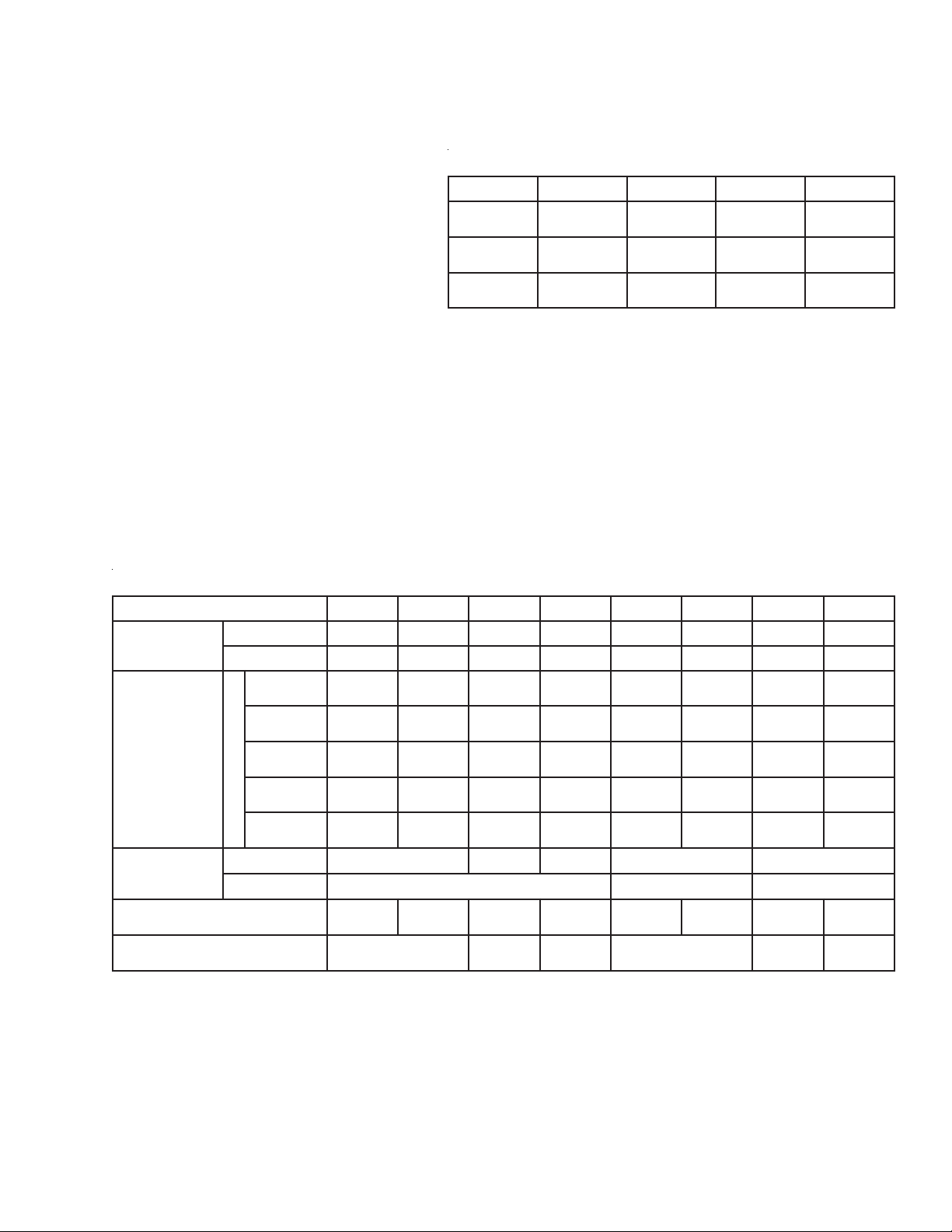
Performance data
NOTE: Maximum capacity varies with the range of suction provided at operating temperature
atadecnamrofreP
noitcusrebmahcnoitsubmoC )cw"( 2.0-3.0-4.0-5.0-6.0-7.0-8.0-9.0-0.1-6.1-
yticapacmumixaM )rh/utBs'0001(
yticapacmuminiM )rh/utBs'0001(
emulovrianoitsubmoC )MFCS(deriuqer
erusserplaitnereffidsaglarutaN )cw"(deriuqer
erusserplaitnereffidsagenaporP )cw"(deriuqer
shtgnelemalfetamixorppA fodnednoyeb
)sehcni(eveelsegrahcsid
0010915720630540455260070080001
01213141517181910252
56080959011021031531541481
1.04.07.02.19.17.27.36.40.64.9
------3.05.08.01.15.18.14.28.3
3-09-681-2112-5142-8172-1203-4262-42
Air volumes shown are for burners without damper,
or with damper in full-open position. If damper is used
to restrict air flow, maximum capacity will be similarly
reduced.
Pilot flame issues from the same gas ports as
main flame, so proof of pilot gas ignition assures
ignition of main gas supply.
Flame sensing can be either by flame rod or UV
scanner when natural gas is the fuel, but only with UV
scanner if propane is the fuel.
Installation is simple, utilizing the built-in, directmounting flange provided.
A complete combustion system utilizing Model
“200” OVENPAK® Burners also includes gas train,
fuel-throttling valve and control system. Your Maxon
representative can help you choose from the broad
range of options available.
seiticapacmumixaM laitnereffidsagleufgnidnopserrochtiw)rh/utBs'0001(
snoitidnocerusserpcitatsrebmahcnoitsubmoccificepstaserusserp
Typical pipe train
12/89
Page 22

Page 2126 Model “200” OVENPAK
Design and Application Details
®
Gas Burners
Differential gas pressures in inches water column
(" wc) for both natural gas and propane are those that
should be measured by connecting a manometer
between test points shown in the photo below.
Model “208” OVENPAK® Burner shown with air damper
and flame rod
Suction (shown in inches wc) should be that
available at operating temperature. It can be determined by a two-step procedure: First, measure cold
suction (chamber to atmosphere). Second, multiply
that reading by the correction factor shown in Graph
"A" for your desired operating temperature.
For example, if you anticipate running the system at 600°F,
follow that dotted line to the right until it intersects curve,
then read downward to a correction factor of 0.5. Therefore,
if you read a cold suction of 1" wc, your expected suction
“at temperature” would be 1" x 0.5 = 0.5" wc.
Dimensions (in inches)
Burner
Assembly
Flame Rod Assembly
 Loading...