

Page 1
Innovative Combustion Solutions Worldwide
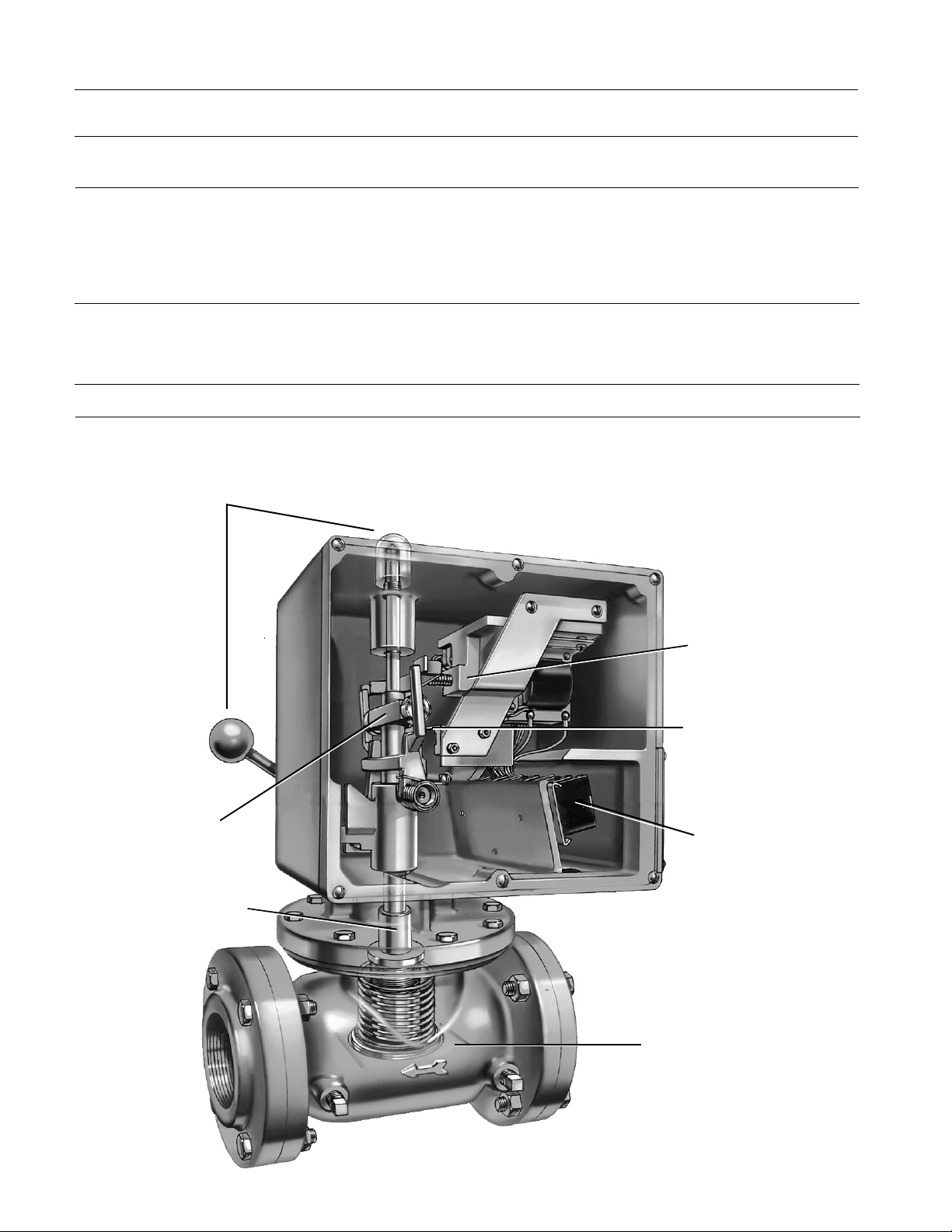
Locktite Manual Reset
• UL listed, FM & CGA approved.
• Snap-acting solenoid for fast closing.
• Two visual indicators of valve position.
• Raintight construction.
• Soft seat disc for positive shut-off.
• Two built-in auxilliary switches.
• Ball bearing trip mechanism reduces wear.
• Lever with extension chains available for
remote mounting.
• 100% factory tested before shipment.
Eclipse 200 LT valves are manually opening valves that automatically shut off the gas
supply to a combustion system when any interlocking limit switch opens. The valve
handle cannot be reset until the condition
causing the open switch is corrected and all
limit switches are closed. Typical limit
switches include air pressure, gas pressure,
temperature limit, and flame monitoring contacts. In the event of a power failure, the
valve immediately closes.
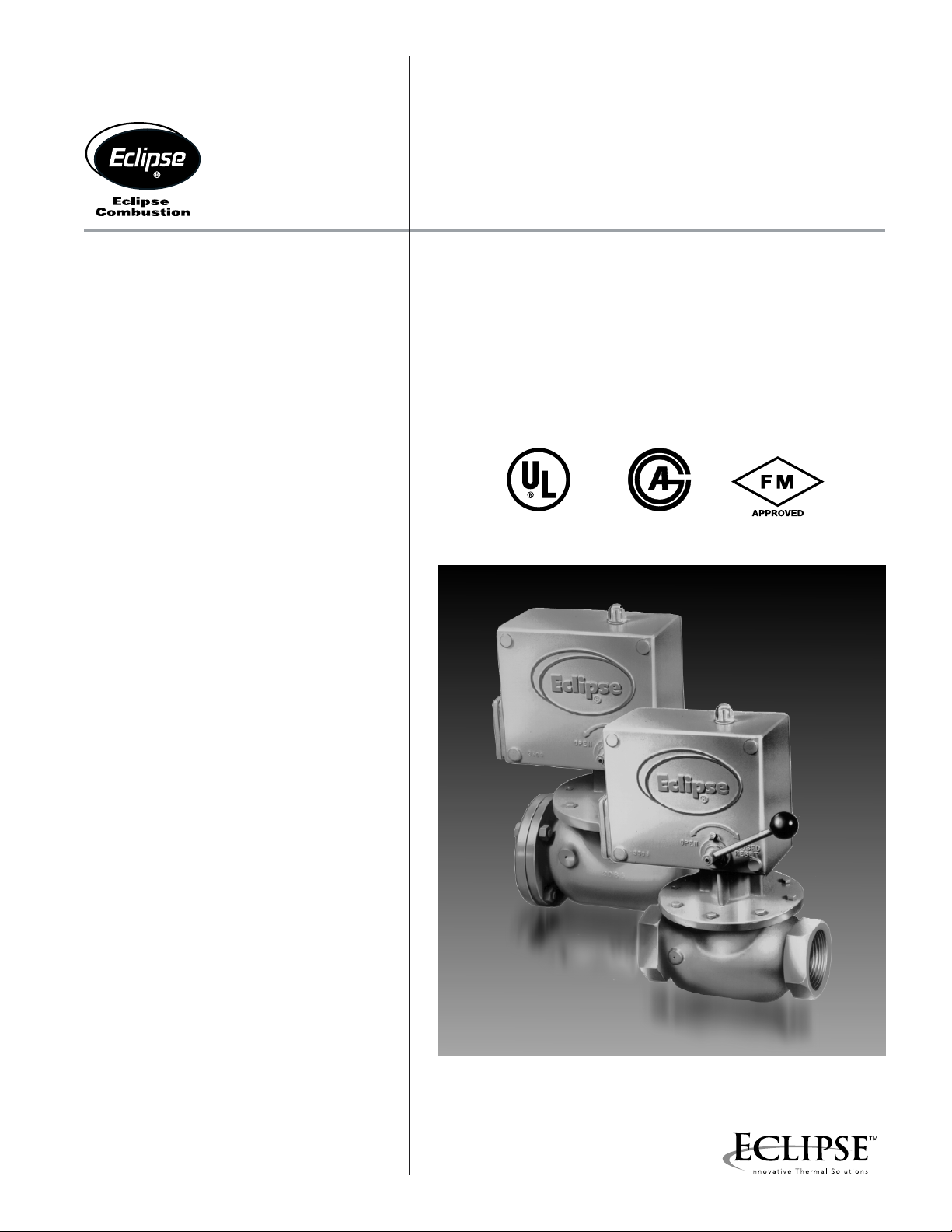
Gas Shut-Off Valves
Series 200 LT
U.S. Patent No. 3,259,357
Canadian Patent No. 764,833
LISTED 326R CGA 3.9
®
Series 200 LT valves include two visual indicators of “open” or “closed” position: a red
“flag” visible in the plastic dome on top of the
valve; and the reset handle position as indicated by cast markings on the operator
case. These valves also include two SPDT
micro-switches that can be used for auxiliary
circuits. Two contacts are made when the
valve opens, and two are made when the
valve is closed.
1” Thru 4”
Flanged
1” Thru 2”
Threaded
Page 2
200 LT Specifications
Temperature Limits +125° to –20° F (+52° to -29° C) fluid and ambient . Below 32° F (0° C) the gas
must be free of water vapor which could condense and freeze within the valve.
Maximum Inlet & 1" thru 2" 30 psig
Differential Pressure 2-1/2" thru 4" 20 psig
Gases UL listed for air, natural gas, LP gas and hydrogen.
FM approved for natural, LP and manufactured gases.
CGA approved for natural and LP gases.
Contact Eclipse for other gases. For corrosive or wet gases such as coke oven or
digester gas, corrosion-resistant valve trim must be installed at Eclipse.
Electrical Volts/Cycles 115/120 volt 50/60 hz standard.
220/50 or 240/60 available.
Holding Current 35 VA at 120 volt
Auxiliary Switches (2) 8 amp, 1/3 hp, 120 or 240 volts A.C.
Approvals UL listed, FM & CGA approved.
Design Features
Two separate visual checks of
valve's open / closed position
Ball bearing tripping & locking
mechanism minimizes friction
& reduces wear
Precision machined and ground
main shaft prevents binding
Snap action, spring
loaded pusher arm
solenoid assembly
designed to provide
quick closure when
electrical signal
is interrupted
Built in microswitch to
make or break other
electrical circuits
Internal terminal strip
accomadates most electric
interlocking protection devices
Valve closes with line pressure,
not against it. Synthetic valve seat
compounded for use with all
commercially available gases
2
Page 3

Capacities*
T
T
210 LT
208 LT
206 L
204 LT
30
20
10
6
4
2
P, "w.c.
1
.6
.4
.2
.1
.1 .2 .4 .6 1 2 4 6 10 20 40 60 100
Capacity, SCFH in 1000's
205 L
212 LT
216 LT
*For natural gas (.6 s.g.) with
an inlet pressure no higher
than 1.1 psig. For other
gases, multiply capacty by:
Butane (2.0 s.g.) .548
Propane (1.5 s.g.) .628
Air (1.0 s.g.) .775
Allowable Mounting Positions
Factory Supplied
Operator Position #1 (Standard) #2 #3 #4
Valve Mounted
With
Operator
Straight
Up or Down
Valve Mounted
With
Wiring Box
Cover
Facing Up
200 LT valves can be supplied with the operator rotated in any of four positions with respect to the valve body, #1, #2, #3, and #4. Position #1
is supplied standard unless otherwise specificed. The sketches above show the allowable mounting orientations for each of the four factorysupplied operator positions. The operator must not be mounted in a position other than those shown.
Note: Incorrect rotation of the operator can result in damage to the microswitch. Please contact your Eclipse representative if rotation
n
of the operator after shipment is required.
3
Page 4

200 LT Dimensions
6-7/8"
175 mm
“D”
O.D.
“A”
N.P.T.
Pipe size
Wiring
Box
Cover
(2) Conduit
Connections
1/2" N.P.T.
6-1/2"
165 mm
7-7/16"
189 mm
F
“C”
Threaded
9-1/2"
241 mm
OPEN
G
“E” Threaded
“E” Flanged
CLOSED
RESET
4-5/16"
110 mm
B
“C”
Flanged
English Units
Catalog C
Number 120 V. 240 V. Open A B C D E F G Lbs.
Assembly Number
V
Threaded Iron Body
204 LT-IS 571604 571604-1 23.4 1 12-1/16 1-1/2 5-1/2 7-1/4 3-11/16 --- 26
205 LT-IS 571605 571605-1 29.8 1-1/4 12-1/16 1-1/2 5-1/2 7-1/4 3-11/16 --- 26
206 LT-IS 571606 571606-1 50.4 1-1/2 12-5/8 2-1/16 5-1/2 9 4-5/16 --- 32
208 LT-IS 571608 571608-1 58.5 2 12-5/8 2-1/16 5-1/2 9 4-5/16 --- 30
Flanged Aluminum Body
204 LT-AF 560604 560604-1 23.4 1 12-3/16 1-3/4 5-7/8 7-1/16 3-13/16 5-7/8 23
205 LT-AF 560605 560605-1 29.8 1-1/4 12-3/16 1-3/4 5-7/8 7-1/16 3-13/16 5-7/8 23
206 LT-AF 560606 560606-1 50.4 1-1/2 12-3/4 2-1/2 5-7/8 9 4-13/16 7 28
208 LT-AF 560608 560608-1 58.5 2 12-3/4 2-1/2 5-7/8 9 4-13/16 7 27
216 LT-AF 560616 560616-1 234.0 4 16-3/16 4 7-15/16 15-5/8 7-13/16 13 60
Flanged Iron Body
210 LT-IF 560611 560611-1 116.0 2-1/2 14-1/8 3-1/16 7-7/8 12-5/8 5-3/4 9-3/4 52
212 LT-IF 560613 560613-1 126.0 3 14-1/8 3-1/16 7-7/8 12-1/4 5-3/4 9-3/4 52
Dimensions In Inches
Net
Catalog C
Number 120 V. 240 V. Open A B C D E F G Kgs.
204 LT-IS 571604 571604-1 23.4 1" 306 38 140 184 94 --- 11.8
205 LT-IS 571605 571605-1 29.8 1-1/4" 306 38 140 184 94 --- 11.8
206 LT-IS 571606 571606-1 50.4 1-1/2" 321 52 140 229 110 --- 14.5
208 LT-IS 571608 571608-1 58.5 2" 321 52 140 229 110 --- 13.6
204 LT-AF 560604 560604-1 23.4 1" 310 44 149 195 97 149 10.4
205 LT-AF 560605 560605-1 29.8 1-1/4" 310 44 149 195 97 149 10.4
206 LT-AF 560606 560606-1 50.4 1-1/2" 324 64 149 229 122 178 12.7
208 LT-AF 560608 560608-1 58.5 2" 324 64 149 229 122 178 12.2
216 LT-AF 560616 560616-1 234.0 4" 411 102 202 397 198 330 27.2
210 LT-IF 560611 560611-1 116.0 2-1/2" 359 78 200 321 146 248 23.5
212 LT-IF 560613 560613-1 126.0 3" 359 78 200 321 146 248 23.5
Bulletin 750 7/01
Metric Units
Assembly Number Dimensions In Millimeters
V
Threaded Iron Body
Flanged Aluminum Body
Flanged Iron Body
Net
 Loading...