

Page 1

T02.0.3X.6C-05 Page 1 of 6
WEEE-Reg.-Nr. DE93889386
GREISINGER electronic GmbH
D - 93128 Regenstauf, Hans-Sachs-Straße 26
+49 (0) 9402 / 9383-0 +49 (0) 9402 / 9383-33 info@greisinger.de
Operating Manual
for Dissolved Oxygen-Measuring transducer
OXY 3610 MP
Specification:
Measuring range: 0.00 to 25.00 mg/l dissolved oxygen
Output signal: refer to type plate
Accuracy: (at nominal temperature)
Display ±1.5% of measured value ±0.2 mg/l
Output signal: ±0.2 % FS
Connection: 4 - 20 mA (2-wire)
Voltage (3- resp. 4-wire)
Electric isolation: input electrically isolated
Auxiliary energy: (supply voltage) Uv = 12 - 30 V DC (4-20mA)
Uv = 18 - 30 V DC (0-10V)
or refer to type plate
Reverse voltage protection: 50V permanent
Perm. impedance (at 4-20mA): RA(Ohm) < ( (Uv - 12V) / 0.02A )
Example: for Uv = 18V: RA < (18V - 12V) / 0.02A => RA < 300 Ohm
Permissible load (at 0-...V): RL(Ohm) > 3000 Ohm
Electrode: Special oxygen electrode GWO3600MU (in scope of supply!)
Electrode type: active diaphragm type, with integrated NTC resistor
Response time: 95% in 10 sec., depending on temperature
Operation life: 3 years er more, depending on proper maintenance
Operating pressure: max. 3 bar.
Mounting diameter: Ø 12,0 ±0,2 mm (also suitable for ½" glanding)
Length: approx. 220 mm (incl. anti-buckling glanding), Mounting length: approx. 110 mm
Weight approx. 180 g
Electrode connection: 5 pole screwable socket
Temperature compensation: automatic, 0 ... 50 °C
Calibration: via keypress at ambient air
Display: approx. 10 mm high, 4-digit LCD-display
Nominal temperature: 20 °C
Operating temperature: 0 to 50 °C (electrode 0 to 40 °C)
Relative humidity: 0 to 95 %RH (non-condensing)
Storage temperature: -20 to 70 °C (electrode 0 to 60 °C)
Housing: ABS (IP65 - with the exception of electrode and temperature probe connection sockets)
Dimensions: 82 x 80 x 55 mm (without elbow-type plug and sensor sockets)
Mounting: With fixing holes for wall mounting (in housing - accessible after cover has been
removed).
Mounting distance: 50 x 70 mm, max. shaft diameter of mounting screws is 4 mm.
Electric connection: elbow-type plug conforming to DIN 43650 (IP65),
max. wire cross section: 1.5 mm², wire/cable diameter from 4.5 to 7 mm
EMC: The
device corresponds to the essential protection ratings established in the Regulations of the
Council for the Approximation of Legislation for the member countries regarding electromagnetic
compatibility (2004/108/EG).
Additional error: <1%
Page 2
T02.0.3X.6C-05 Page 2 of 6
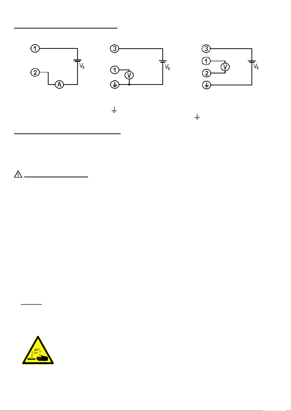
Assignment of elbow-type plug:
2-wire connection (4-20mA) 3-wire connection (voltage) 4- wire connection (voltage)
1 = supply voltage +Vs 1 = signal + 1 = signal +
2 = GND / signal 3 = supply voltage +Vs 2 = signal -
(4) = supply voltage -Vs 3 = supply voltage +Vs
signal - (4) = supply voltage -Vs
General installation instructions:
To mount the connection cable (2-, 3-, or 4-wire depending on type of device) the elbow-type plug screw has to be
loosened and the coupling insert has to be removed by means of a screw driver at the position indicated (arrow).
Pull out connection cable through PG glanding and connect to the loose coupling insert as described in the wiring
diagram. Replace loose coupling insert onto the pins at the transducer housing and turn cover cap with PG glanding in
the direction desired till it snaps on (4 different starting positions at 90° intervals). Re-tighten the screw at the angle plug.
Safety instructions:
This device has been designed and tested in accordance with the safety regulations for electronic devices.
However, its trouble-free operation and reliability cannot be guaranteed unless the standard safety measures and special
safety advises given in this manual will be adhered to when using the device.
1. Trouble-free operation and reliability of the device can only be guaranteed if the device is not subjected to any other
climatic conditions than those stated under "Specification". If the device is transported from a cold to a warm
environment condensation may cause in a failure of the function. In such a case make sure the device temperature
has adjusted to the ambient temperature before trying a new start-up.
2. General instructions and safety regulations for electric, light and heavy current plants, including domestic safety
regulations (e.g. VDE), have to be observed.
3. If device is to be connected to other devices (e.g. via PC) the circuitry has to be designed most carefully. Internal
connection in third party devices (e.g. connection GND and earth) may result in not-permissible voltages impairing or
destroying the device or another device connected.
4. If there is a risk whatsoever involved in running it, the device has to be switched off immediately and to be marked
accordingly to avoid re-starting.
Operator safety may be a risk if:
- there is visible damage to the device
- the device is not working as specified
- the device has been stored under unsuitable conditions for a longer time.
In case of doubt, please return device to manufacturer for repair or maintenance.
5. Warning:
Do not use these product as safety or emergency stop devices, or in any other application where failure of the product
could result in personal injury or material damage.
Failure to comply with these instructions could result in death or serious injury and material damage.
6. Caution, acid! The electrode contains KOH. KOH can cause severe chemical burns!
If leaking, avoid contact!
If there was contact:
• to skin: Flush contacted area with large amounts of water for several minutes.
• to clothing: remove contaminated clothing.
• to eyes: Flush with large amounts of water for several minutes,
obtain medical treatment.
After swallowing:
• give large volumes of water. DO NOT induce vomiting!
• Obtain medical treatment.
Page 3

T02.0.3X.6C-05 Page 3 of 6
Display
Meaning
Possible fault causes
Remedy
CFE.1
Temperature out of
allowed range
Temperature has to be within 5 to 40°C
Calibrate again at correct temperature
electrode error
Temperature sensing defective
Check cable, connection, replace
electrode if necessary
CFE.3
Wrong signal: to low
Membrane dried out/electrode used up
Electrode maintenance / replace
CFE.4
Wrong signal: to high
Calibration surrounding not valid
Check Calibration surrounding
CFE.6
Instable signal
Calibration surrounding not valid
Check Calibration surrounding
Display functions:
During normal operation the oxygen content is displayed in the unit [mg/l]. By pressing the Key 2 (down) the
temperature at the electrode can be shown, pressing key 3 (up) shows the state of the electrode in [%]. The state is
calculated and stored during the calibration (see below). The displays of the state and the temperature of the electrode
are marked by small arrows at the upper end of the display. After 5 seconds the transducer display switches
automatically back to the oxygen value.
display dissolved oxygen display electrode temperature display state of electrode
Calibration of the electrode:
Expose electrode to the ambient air, wait until the temperature has adopted to the ambient conditions.
Press key "SET" for 5 sec., The display shows "CAL".
After approx. 10 sec’s the transducer is calibrated or a referring error message will be shown:
Important!! Oxygen electrodes are sensitive components. Please read the referring manual prior to use.
During calibration the state of the electrode is evaluated: 100% means perfect state, 40 % means e.g. electrode has a
weak output signal and needs to be regenerated or replaced soon (p.r.t. electrode manual). The state of the electrode can
be displayed with key 3 (up).
Configuration of the device
For the correct function of the device in its application, it has to be configured to meaningful settings.
For doing this the cover has to be removed. Then the jumper J1 right above of key 2 has to be set.
Then use following configuration procedure:
1. Press key one more than 5 sec’s until OFFS appears in
the display. Now OFFS and the referring setting are shown alternating
I.) OFFSET of the measuring „OFFS“ :
The offset is entered in mg/l. It can be used to compensate different effects, e.g. special
approaching flow conditions of the application. Please refer to Appendix A
2. Enter the desired value by using keys 2 (down) and 3 (up).
Input range: -1.00...+0.00 mg/l
3. Acknowledge the value with key 1 (set): The display shows „PAbS“
Page 4

T02.0.3X.6C-05 Page 4 of 6
Display
Description
Possible fault cause
Remedy
FE 1
measuring range exceeded
Calibration is wrong
Wrong signal
Recalibrate the transducer.
FE 2
Measuring values below
measuring range
Wrong signal
Check the connections, cable and electrode.
FE 7
System fault
Error in device
Disconnect from supply and reconnect. If error
remains: return to manufacturer
FE 9
Input signal is not valid
Sensor not connected or
cable defective
Check sensor, cable and connections
8.8.8.8
Segment test
The transducer performs a display test for 2 seconds after power up. After
that it will change to the display of the measuring.
Input signal is not valid
Permissible input range is
exceeded
Check if not a wrong electrode is connected.
Replace electrode.
-0,6
-0,4
-0,2
0
0,3 0,5 0,7 0,9 1,1 1,3 1,5 1,7 1,9
v [m/s]
Offset [mg/l]
II.) Average ambient absolute pressure „PAbS“ (function of the altitude above sea level):
Necessary for a correct evaluation of the state of the electrode. If the application works for example at an altitude of
350 m above sea level, 980mbar is a correct setting. Please refer to Appendix B
4. Enter the desired value by using keys 2 (down) and 3 (up).
Input range: 500...2000 mbar
5. Acknowledge the value with key 1 (set): The display shows „FilLt“
III.) Display damping „FiLt“:
By this factor the ‘speed’ of the display can be adopted to the application. This is intended to reduce instabilities in the
measured value as they appear in some specialised applications
6. Enter the desired value by using keys 2 (down) and 3 (up).
Input range: 0...15 (0: fast display, 15: slow display. Setting ex works: 10)
7. Acknowledge the value with key 1 (set).
8. The settings are stored. The unit starts up again. (8888 in display)
Attention: Bring back the jumper j1 to the ‚parking position‘ after configuration (one contact connected, the
second contact ‚on air‘)!
Then the device can be calibrated by key 1 and the configuration data is protected.
Error and System Messages
Appendix A: Offset settings for different applications
The Offset setting is supposed to correct measuring deviations caused by different flow speed (v) around the electrode:
For activated sludge basins and at flow speeds > 1m/s a offset setting
of ca –0,6 should be entered.
In between 0,3 and 1m/s the offset can be read from the diagram.
0,3m/s correspond to the speed that is achieved by stirring by hand.
Flow speeds below 0,3 m/s are not sufficient to get a correct and
reproducible measuring.
Page 5

T02.0.3X.6C-05 Page 5 of 6
Altitude [m]
Pabs[mbar)
Altitude[m]
Pabs[mbar)
-100
1025
900
909 0 1013
1000
898
100
1001
1200
877
200
989 1400
856
300
977 1600
835
400
966 1800
814
500
954 2000
794
600
943 2500
746
700
932 3000
701
800
920 4000
616
Replenishing hole
Electrode shaft
O-ring
Diaphragm head
Appendix B: abs. ambient pressure as a function of the altitude above sea level
Values between are to be interpolated
Appendix C: the oxygen electrode:
The oxygen electrode is an active electrode consisting of a silver cathode and a lead
anode using potassium hydroxide (KOH) as an electrolyte. In case of oxygen being
present it will be reduced at the silver cathode and the electrode produces electric
current. In case of no oxygen being present not current will be produced. Both the
silver cathode and the lead anode will be used up during oxygen measuring. The
electrode ages. We, therefore, recommend regular maintenance of the electrode at
monthly intervals (p.r.t. ‘Electrode maintenance’).
Electrode design:
The electrode housing is made of PVC. With the exception of the electrode shaft all
parts need to be maintained regularly and be replaced if necessary.
o Protective flask: The protective flask is used to moisten the diaphragm. The service
life of the electrode will be prolonged. The protective flask contains water.
Attention! Use water only; never use potassium chloride (KCI); this is only required for
storage of pH-electrode.
o Diaphragm head: the diaphragm head is covered with a teflon diaphragm. It will be
filled with KOH electrolyte and screwed onto the electrode shaft (no air bubbles).
Damages in the diaphragm, large air bubbles or air bubble rings in the diaphragm head
will result in erroneous measurements. This may also be the reason for errors in the
calibration. The diaphragm head is a spare part and can be ordered individually.
o Filling hole: If the electrode is used at high temperatures or if it has been stored
without its protective flask for a longer period of time, some electrolyte will be lost due
to evaporation. If necessary unscrew diaphragm head, remove locking screws and top
up electrolyte using a syringe. Replace and tighten locking screws. Normally some
electrolyte can be observed penetrating at the silver cathode.
When is electrode maintenance required:
• Unless it is used the electrode is to be stored in the protective flask filled with water or directly in a vessel filled with
dechlorinated water.
• Residues of bacteria, fungi or algae must be removed prior to measuring using a soft paper towel.
• If a calibration can no longer be carried out or if the membrane is damaged the electrode needs maintenance.
• In the course of the time air bubbles may accumulated underneath the membrane. As long as they are small and do not
affect the silver cathode the measurements will not be influenced. If, however, there is a large ring of air bubbles
underneath the membrane covering the silver cathode, the electrode needs maintenance.
! Attention during maintenance is required as the electrolyte is highly corrosive !
Use disposable gloves during maintenance, if available, or rinse hands thoroughly with water.
Page 6

T02.0.3X.6C-05 Page 6 of 6
Electrode maintenance:
1. Prepare liquid absorbing paper towel.
2. Remove membrane head and wipe off electrolyte solution with paper cloth.
Do not touch electrolyte. If your skin has come into contact with electrolyte, rinse thoroughly with clear water.
3. Clean silver cathode using sand paper (grain size 240). Do not shine silver cathode as its surface needs to be rough
so that the electrolyte can be dispersed evenly. Remove any dust from grinding.
4. If necessary take out replenishing screw and top up with electrolyte till it is spilling out (e.g. using a disposable
syringe). Put back replenishing screw. (normally not necessary)
5. Put new membrane head on the paper towel and fill up with electrolyte making sure there are no air bubbles.
6. Put electrode into head vertically from above till the thread catches. Then take up head with paper towel and screw
onto electrode from underneath. Electrolyte will be displaced from the membrane head, flowing over.
7. Mop up excess electrolyte using paper towel.
8. Turn electrode around and check for air bubbles. If there are no air bubbles or only tiny ones the maintenance has
been completed. If there are large air bubbles the process has to be repeated.
If O-ring has been damaged, it has to be replaced.
Please note: Prior to its being calibrated again the electrode needs to be lying on a table for at least 3 hours.
If electrode can no longer be calibrated although it has been properly maintained, the electrode needs to be returned to
manufacturer for check up and may have to be replaced.
How to Operate:
a.) Store the oxygen electrode always in water, either in the protective flask, or directly in a vessel filled with
dechlorinated water. For storage in the protective flask first push the cap oh the electrode second the o-ring and
thereafter put the electrode in the flask and screw the cap down the flask.
If the diaphragm has dried up the electrode must be soaked in water for approx. 2 h prior to measuring start-up. Then
a calibration can be carried out without any problems.
b.) The electrode are only suitable for the devices OXY3610MP. Unsuitable devices may lead to the destruction of the
measuring device and the oxygen electrode.
c.) For measuring remove the protective flask of the electrode
d.) Please note: the electrode measurement is sensitive against shocks!
By stirring of the electrode in the measured liquid be careful that the electrode does not hit the container. A vibration of
the electrode has a effect to the measured value.
Disposal instructions
The electrode contains lead and caustic electrolyte. Dispose as special waste.
According to the ElektroG (law for bringing into market, the return and the environmentally friendly disposal of
electronic equipment) we accept the return of the electrode and the device.
Send the device or electrode directly to us (sufficiently stamped), if it should be disposed. We will dispose it
appropriately and environmentally friendly.
 Loading...