


E26.0.02.6B-02 Blatt 1 von 2
Bedienungsanleitung für Digital-Einbau-Thermometer
GTH 2448 / 2
und GTH 2448 / 3
Technische Daten:
Meßbereich: GTH2448/2: -200 ... +650 °C
GTH2448/3: -60.0 ... +199.9 °C
Auflösung: GTH2448/2: 1 °C
GTH2448/3: 0.1 °C
Fühleranschluß: Pt100, 2-Leiter
Genauigkeit: ± 0.5°C ±1 Digit
Offsetabgleich: Die Nullpunktverschiebung des Sensors (z.B. durch lange Kabel) kann mit Hilfe eines auf
der Geräterückseite befindlichen Spindeltrimmers abgeglichen werden.
Anzeige: 10 mm hohe, 3½-stellige rote LED-Anzeige
Abtastrate: ca. 3 Messungen/sec.
Nenntemperatur: 25°C
Arbeitstemperatur: 0 bis 50°C
Relative Luftfeuchtigkeit: 5 bis 95 % r.F. (nicht betauend)
Lagertemperatur: -20 bis 85°C
Spannungsversorgung: 12 V DC (8 - 20 V DC) oder 24 V DC (18 - 29 V DC) bzw.
12 V AC (8 - 20 V AC) oder 24 V AC (18 - 27 V AC) (einstellbar über Lötbrücke)
Stromverbrauch: max. 20 mA
Gehäuse: glasfaserverstärktes Noryl, Frontscheibe PC.
Abmessungen: 24 x 48 mm (H x B) (Frontrahmenmaß)
Einbautiefe: ca. 65 mm (inkl. Schraub-/Steckklemmen)
Panelbefestigung: mit VA-Federklammer, mögliche Paneldicken: von 1 bis ca. 10 mm
Schalttafelausschnitt: 21.7
+0.5
x 45
+0.5
mm (H x B).
Anschlußklemmen: 4-polige Schraub-/Steckklemme für Leiterquerschnitte von 0.14 bis 1.5 mm²
Störfestigkeit (EMV): Das Gerät ist geprüft nach EN50081-1 und EN50082-2
zusätzlicher Fehler: <1%
Schutzklasse: frontseitig IP54 (mit optionellen O-Ringen IP65).
Zubehör:
(kleine Auswahl - komplette Übersicht siehe Katalog)
GNG220/1-12V Netzgerät für GTH2448: Eingang: 230V AC; Ausgang: 12V DC stabilisiert, max. 40mA
IP65 SET O-Ringe (2 Stück) für frontseitige Schutzklasse IP65
GTF 102 / Pt100, 2-Leiter -200 ... +600°C Fühler z.B. zum Einschrauben in Meßobjekt, etc.
-50 ... +400°C Beliebige Rohrdurchmesser, -längen oder Gewinde möglich - siehe Katalog
GTF 103 / Pt100, 2-Leiter -200 ... +600°C Fühler mit Anschlußkopf (DIN B), R1/2", FL = 100mm, D = Ø 6mm
-50 ... +400°C (weitere Ausführungen siehe Katalog)
GTF 200 Pt 100 -50 ... +200°C, Pt100 4-Leiter, Fühlerhülse (Ø5 x 50mm) aus Edelstahl, ca. 1m Siliconkabel
GTF 1002 -50 ... +400°C, Pt100 4-Leiter, Fühlerrohr (Ø3 x 100mm) aus Edelstahl, ca. 1m Siliconkabel
Hinweis: Einige der angebenen Fühler sind 4-Leiter-Fühler. Beim Anschluß dieser Fühler an ein GTH2448 werden einfach
die beiden gleichfarbigen Adern gemeinsam in eine Klemme geschraubt.
E26.0.02.6B-02 Blatt 2 von 2
Sicherheitsbestimmungen
Beachten Sie grundsätzlich folgende Punkte, um eine Gefährdung des Bedieners auszuschließen:
a) Setzen Sie das Gerät bei erkennbaren Beschädigungen oder Funktionsstörungen sofort außer Betrieb.
b) Trennen Sie das Gerät vor dem Öffnen von der Versorgungsspannung. Achten Sie bei der Montage von Gerät und Anschlüs-
sen darauf, daß alle Teile gegen direktes Berühren geschützt sind.
c) Beachten Sie die üblichen Vorschriften und Sicherheitsbestimmungen für Elektro-, Schwach- und Starkstromanlagen,
insbesondere die landesüblichen Sicherheitsbestimmungen (z.B. VDE 0100).
d) Konzipieren Sie die Beschaltung besonders sorgfältig beim Anschluß an andere Geräte. Unter Umständen können interne
Verbindungen in Fremdgeräten zu nicht erlaubten Spannungspotentialen führen.
Elektrischer Anschluß:
Die Anschlüsse des GTH 2448 / 2 bzw. GTH 2448 /3 befinden sich auf der Rückseite des Gerätes.
Der Anschluß erfolgt über Schraub-/Steckklemmen.
Schraub-/Steckklemmen sind grundsätzlich im losen Zustand zu montieren und anschließend erst aufzustecken.
Bei Montage an gesteckten Klemmen können Lötaugen losgerissen werden. Bitte verwenden Sie einen passenden
Schraubenzieher und ziehen Sie die Schrauben nicht mit Gewalt an.
Versorgungsspannung: 12 V DC/AC bzw. 24 V DC/AC
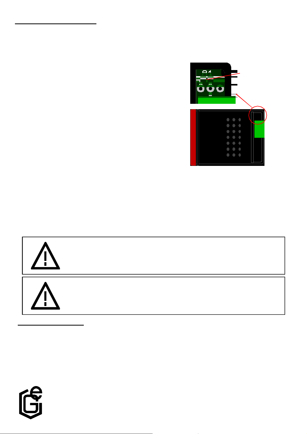
Die Auswahl der Versorgungsspannung erfolgt über eine Lötbrücke
neben der Anschlußklemme.
Bitte vergewissern Sie sich, daß die Versorgungsspannung mit dem
eingestellten Spannungsbereich übereinstimmt
Brücke "A1" offen: 24 V ( 18 - 29 V DC o. 18 - 27V AC )
Brücke "A1" geschlossen: 12 V ( 8 - 20 V DC o. 8 - 20 V AC)
Fühleranschluß: Pt100, 2-Leiter
Der Anschluß bzw. die Inbetriebnahme darf nur durch fachlich
qualifizierte Personen erfolgen. Bei falschem Anschluß kann das
Gerät zerstört werden -- kein Garantieanspruch
Lötbrücke A1
Warnung: Beim Betrieb elektrischer Geräte stehen zwangsläufig Teile dieser Geräte unter gefährlicher
Spannung. Bei Nichtbeachtung der Warnhinweise können deshalb schwere Körperverletzungen oder Sachschäden auftreten. Nur entsprechend qualifiziertes Personal sollte an
diesem Gerät arbeiten. Der einwandfreie und sichere Betrieb dieses Gerätes setzt sachgemäßen Transport, fachgerechte Lagerung, Aufstellung und Montage sowie sorgfältige
Bedienung und Instandhaltung voraus.
Warnung:
Benützen Sie dieses Produkt nicht in Sicherheits- oder in Notaus-Einrichtungen oder in Anwendungen wo ein
Fehlverhalten des Gerätes die Verletzung von Personen oder materielle Schäden zur Folge haben kann.
Wird dieser Hinweis nicht beachtet so kann dies zu Verletzung oder zum Tod von Personen sowie zu
materiellen Schäden führen.
Qualifiziertes Personal
sind Personen, die mit Aufstellung, Montage, Inbetriebnahme und Betrieb des Produktes vertraut sind und über die
ihrer Tätigkeit entsprechende Qualifikation verfügen. Zum Beispiel:
n Ausbildung oder Unterweisung bzw. Berechtigung, Stromkreise und Geräte/Systeme gemäß den Standards der Sicherheits-
technik ein- und auszuschalten, freizuschalten, zu erden und zu kennzeichnen.
n Ausbildung oder Unterweisung gemäß dem Standard der Sicherheitstechnik in Pflege und Gebrauch angemessener
Sicherheitsausrüstung.
n Schulung in Erster Hilfe.
GREISINGER electronic GmbH
D - 93128 Regenstauf, Hans-Sachs-Straße 26
Tel.: 09402 / 9383-0
Fax: 09402 / 9383-33

E26.0.02.6C-02 page 1 of 2
Operating Manual for Digital Thermometer
GTH 2448 / 2
and GTH 2448 / 3
Specification:
Measuring range: GTH2448/2: -200 ... +650 °C
GTH2448/3: -60.0 ... +199.9 °C
Resolution: GTH2448/2: 1 °C
GTH2448/3: 0.1 °C
Probe connection: Pt100, 2-wire, (probe not included in scope of supply)
Accuracy: ± 0.5°C ±1 Digit
Offset adjustment: An Offset of the sensor (e.g. when using long cable) can be compensated with the spindle
potentiometer at the backside of the housing.
Display: 3½-digit, red LED-display, 10 mm high
Scan rate: approx. 3 measurements/sec.
Nominal temperature: 25°C
Working temperature: 0 to 50°C
Relative humidity: 5 to 95 % r.h. (non-condensing)
Storage temperature: -20 to 85°C
Voltage supply: 12 V DC (8 - 20 V DC) or 24 V DC (18 - 29 V DC) resp.
12 V AC (8 - 20 V AC) or 24 V AC (18 - 27 V AC) (to be set via soldering jumper)
Power consumption: max. 20 mA
Housing: glass fibre reinforced Noryl, front screen PC.
Dimensions: 24 x 48 mm (H x W) (dimensions of front frame)
Mounting depth: approx. 65 mm (incl. screw-type/plug-in terminals)
Panel mounting: by means of VA- elastic spike, allowed panel thickness: from 1 to approx. 10 mm
Panel cut-out: 21.7
+0.5
x 45
+0.5
mm (H x W).
Connection terminals: 4-pin screw-type/plug-in terminals for wire dias ranging from 0.14 to 1.5 mm²
EMC: Device has been tested according to EN50081-1 and EN50082-2
additional fault: <1%
IP rating: front IP54 (with optional O-rings IP65).
Accessories:
(small selection - for our complete accessories refer to our catalogue)
GNG220/1-12V power supply (230VAC) for GIA2448 input: 230V AC; output: 12V DC stabilised, max. 40mA
IP65 SET O-rings (2 pcs.) O-rings for IP rating IP65 at the front
GTF 102 / Pt100, 2-wire -200 ... +600°C probe e.g. for screwing in to measuring object.
-50 ... +400°C arbitrary tube diameters, lengths and threads are possible - refer to catalogue
GTF 103 / Pt100, 2-wire -200 ... +600°C probe with connection head (DIN B), R1/2", FL = 100mm, D = dia 6mm
-50 ... +400°C (outer configuration refer to catalog)
GTF 200 Pt 100 -50 ... +200°C, Pt100 4-wire, stainless steel probe head (Ø5 x 50mm), app. 1m silicon cable
GTF 1002 -50 ... +400°C, Pt100 4-wire, stainless steel tube (Ø3 x 100mm), approx. 1m silicon cable
Note: Some of these probes are 4-wire probes. To connect them to the GTH2448 just screw the equally coloured wings
together in one terminal.

E26.0.02.6C-02 page 2 of 2
soldering jumper A1
Elektrischer Anschluß:
Electric connections for the GTH 2448 / 2 or GTH 2448 / 3 are located at the back of the device.
Connection is made via screw-type/plug-in terminals (max. terminal range 1,5mm²).
Make it a rule to always mount screw-type/plug-in terminals while they are still loose and connect only later.
If terminals are mounted after connection there is a risk that soldering eyes may come loose. Please use suitable
screw-driver and do not tighten screws by force.
Supply voltage: 12 V DC/AC or 24 V DC/AC
Terminal assignment: +Uv = supply voltage +
GND = supply voltage -
Please make sure to check if supply voltage and voltage range set
conform to each other.
Use the soldering jumper next to the connection terminal to select
supply voltage:
Jumper "A1" open: 24 V ( 18 - 29 V DC or 18 - 27 V AC)
Jumper "A1" closed: 12 V ( 8 - 20 V DC or 8 - 20 V AC)
Probe connection: Pt100, 2-wire
Both the connection and commissioning of the device must only be carried
out by skilled personnel. In case of a wrong connection, the device may be
destroyed - no warranty claims can be accepted !
Safety regulations
Make it a rule to always observe the following points to exclude any risk whatsoever for the operator.
a) In case of any obvious damage and/or functional problems disconnect device immediately
b) Prior to opening it, disconnect device and supply voltage source. Make sure that all parts of the device are protected against
direct touching when mounting the device and setting its connections.
c) Please always adhere to the standard safety regulations for electric devices, power systems and light-current installations,
and make sure that your national safety regulations (e.g. VDE 0100) are observed.
d) If device is to be connected to other devices (e.g. via serial interface) the circuitry has to be designed most carefully. Internal
connection in third party devices may result in not-permissible voltages.
Skilled personnel
These are persons who are familiar with the installation, mounting, commissioning and the operation of the product and have
acquired a qualification for their job:
n Training or instructions or qualification to switch on/off, isolate, ground and apply markings to circuits and devices/systems
in accordance with the latest state of the art standards of safety technology.
n Training or instructions regarding the proper care and use of suitable safety equipment in accordance with the latest state of
the art standards of safety technology.
n First aid training.
Warning: When operating electric devices parts of these devices will, as a matter of course, be live.
Unless the warnings are observed severe damage to life and limb or to property may be the
result. Make sure that only skilled personnel is working with this device. Trouble-free
operation of this device can only be guaranteed if it is properly transported and stored.
Carefull installation, mounting, operation and maintenance are vital factors for the safe
operation of this device.
Warning:
Do not use these product as safety or emergency stop devices, or in any other application where
failure of the product could result in personal injury or material damage.
Failure to comply with these instructions could result in death or serious injury and material damage.
 Loading...