

E
G
S
C
T38.0.0X.6C-03
CO2 - Transmitter
Operating Manual
GT10 -
O2 - 1R
GR
D - 93
Tel.: +49
ISINGER electronic
128 Regenstauf, Hans-Sachs-
9402 / 9383-0, Fax: +49 9402 / 9383-33, eMail: info
mbH
traße 26
@greisinger.de

T38.0.0X.6C-03 Page 2 of 7
Content
1. Intended use .............................................................................................................................. 3
2. General advice .......................................................................................................................... 3
3. Safety instructions ..................................................................................................................... 3
4. Disposal notes ........................................................................................................................... 3
5. Installation ................................................................................................................................. 4
5.1 Dimensions ......................................................................................................................... 4
5.2 Elbow-type plug installation instruction ............................................................................... 4
5.3 Assignment of elbow-type plug ........................................................................................... 4
6. Operation ................................................................................................................................... 5
6.1 Display functions ................................................................................................................. 5
6.2 Error an System messages ................................................................................................. 5
7. Configuration ............................................................................................................................. 6
7.1 Description of configuration parameter: .............................................................................. 6
8. Specification .............................................................................................................................. 7

T38.0.0X.6C-03 Page 3 of 7
1. Intended use
CO2 gas is outweigh than air (rel. density = 1.52).
The suggested mounting level is near the floor.
Range of application:
• Air conditioning
• Ambient air
• Carbon dioxide in green house
etc.
2. General advice
Read through this document attentively and make yourself familiar to the operation of the device before you
use it. Keep this document in a ready-to-hand way in order to be able to look up in the case of doubt.
3. Safety instructions
This device was designed and tested considering the safety regulations for electronic measuring devices.
Faultless operation and reliability in operation of the measuring device can only be assured if the
General Safety Measures and the devices specific safety regulation mentioned in this user’s manual are
considered.
1. Faultless operation and reliability in operation of the measuring device can only be assured if the device
is used within the climatic conditions specified in the chapter “Specifications“.
2. By faulty handling of the interface adapter a damage of the device cannot be excluded. Likewise a
damage of your attached device is possible.
In such case we cannot assume any warranty.
The manufacturer will not assume any warranty for damages to other devices resulting by use of the
interface adapter.
3. Standard regulations for operation and safety for electrical, light and heavy current equipment have to be
observed, with particular attention paid to the national safety regulations.
4. When connecting the device to other devices (e.g. the PC) the interconnection has to be designed most
thoroughly, as internal connections in third-party devices (e.g. connection of ground with protective
earth) may lead to undesired voltage potentials.
5. The device must be switched off and must be marked against using again, in case of obvious
malfunctions of the device which are e.g.:
• visible damage
• no pre-scripted working of the device
• storing the device under inappropriate conditions for longer time
When not sure, the device should be sent to the manufacturer for repairing or servicing.
6. Attention: Do not use this product as safety or emergency stopping device or in any other application
where failure of the product could result in personal injury or material damage. Failure to comply with
these instructions could result in serious injury and material damage.
4. Disposal notes
The device must not be disposed in the regular domestic waste.
Send the device directly to us (sufficiently stamped), if it should be disposed.
We will dispose the device appropriate and environmentally sound.
T38.0.0X.6C-03 Page 4 of 7
A /
5. Installation
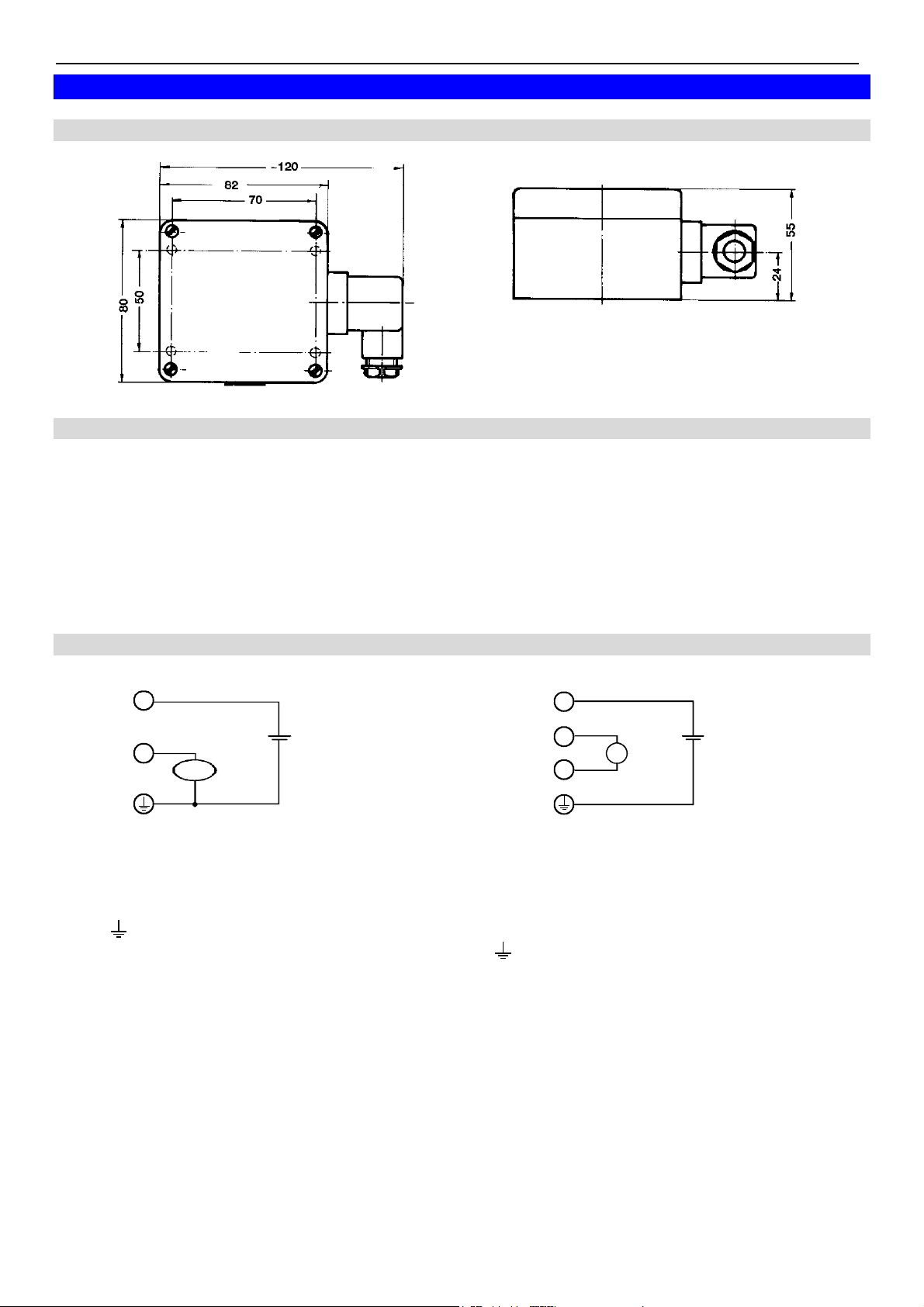
5.1 Dimensions
5.2 Elbow-type plug installation instruction
To mount the connection cable (3-, or 4-wire depending on type of device) the elbow-type plug
screw has to be loosened and the coupling insert has to be removed by means of a screw driver at
the position indicated (arrow).
Pull out connection cable through fitting and connect to the loose coupling insert as described in
the wiring diagram. Replace loose coupling insert onto the pins at the transducer housing and turn
cover cap with fitting in the direction desired till it snaps on
(4 different starting positions at 90° intervals).
Re-tighten the screw at the angle plug.
5.3 Assignment of elbow-type plug
3
1
V
Uv
3
1
2
V
Uv
3-wire-connection (mA or voltage) 4-wire-connection (voltage)
1 = signal + 1 = signal +
3 = supply voltage +Uv 2 = signal –
(4) = supply voltage -Uv 3 = supply voltage +Uv
signal - (4) = supply voltage –Uv
Note: terminal 2 and 4 are connected in the device.
The type current or voltage output is set by works and cannot be changed.

T38.0.0X.6C-03 Page 5 of 7
6. Operation
6.1 Display functions
Currently measured values: During normal operation the CO2 display value is displayed in ppm.
Min- / Max-value memory:
Watch min values (Lo): press ▼ shortly once display changes between
Lo- und Min-values
Watch max values (Hi): press ▲ shortly once display changes between
Hi- und Max-values
Restore current values: press ▲ or ▼ once again current values are displayed
Clear min values: press ▼ for 2 seconds Min values are cleared.
The display shows shortly “CLr” (Clear)
Clear max values: press ▲ for 2 seconds Max values are cleared.
The display shows shortly “CLr” (Clear)
After 10 seconds the currently measured values will be displayed again.
Min- / Max- Alarm:
Whenever the measured value is exceeding or undershooting the alarm-values that have set, the alarmvalue and the measuring value will be displayed alternating.
AL.Lo the lower alarm boundary is been reached or is undershot.
AL.Hi the upper alarm boundary is been reached or is exceeded.
6.2 Error an System messages
Display Description Possible fault cause Remedy
Err.1
Err.7
Measuring range
exceeded
Wrong signal. Take care for fresh air.
System fault Error in device. Disconnect from supply and
reconnect. If error remains
Err.9 Sensor error Sensor defective.
Er.11
Calculation not possible
Calculation variable
missing or invalid.
return device to manufacturer.
Check temperature.
The transducer performs a display test for 8 seconds after
8.8.8.8
Segment test
power up. After that it will change to the display of the
measuring.

T38.0.0X.6C-03 Page 6 of 7
7. Configuration
In the configuration the device parameters can be changed.
The jumper has be set, p.r.t. figure right-hand side. To set or
remove jumper, the housing cover has to be removed.
Ex works the jumper is set.
To change parameters press “SET” (Taste 1) four seconds, than
Jumper
the parameters selection is started with the first parameter
(display shows “dA.Lo”).
By pressing “SET” the desired parameter is selected, the editing of
the parameter values happens via key
▲ (key 3) or ▼ (key 2).
Pressing “SET” again (after editing the parameter values) returns
to the parameter selection.
Pressing “SET” again after the last parameter finishes the
configuration, stores the changes and the instrument returns to the
normal mode.
If the jumper is removed from the shown
contacts, the configuration is
inaccessible, values are protected.
7.1 Description of configuration parameter:
a) 'dA.Lo': Display at zero output (output scaling)
Enter the display value at which the output should have 4mA (or 0V).
b) 'dA.Hi': Display at maximum output (output scaling)
Enter the value at which the output should have 20mA (or 1 / 10V).
c) 'DA.Er': Preferred state of output
Display
Lo
Hi
Preferred state of the
analog output
In case of failure inactive
In case of failure active
Annotation
Output signal = <3,7 mA or 0 V
Output signal = >23 mA or >10.5 V (or >1.1 V)
d) 'AL.Hi': Upper boundary of alarm
At Al.Hi the boundary is set from which max. alarm will be given.
Selectable range: ‚AL.Lo‘ ... 2001
e) 'AL.Lo': Lower boundary of alarm
At Al.Lo the boundary is set from which min. alarm will be given.
Selectable range: -1 ... ‚AL.Hi‘
f) 'A.dEL': Alarm delay
The value at A.dEL declares the alarm delay in minutes.
g) 'OFFS': Offset of CO
-measuring
2
The offset of the measuring will be shifted by this value, the input is in ppm. (calculation: see by scale)
Selectable range: -200 ... +200 ppm or “oFF”: offset is deactivated (0 = ex works)
h) 'SCAL': Scale correction of CO
-measuring
2
The scale of the measuring is changed by this value.
Selectable range: -10.00...+10.00 or “oFF”: scale is deactivated (0 = ex works)
The adjusting by offset and scale is intended to be used to compensate deviations of the measuring.
It is recommended to keep the scale correction deactivated (“oFF”). The display value is given by
following formula:
CO2-display = measured value – offset
With a scale correction the formula changes:
CO2 display = (meas. value - offset) * (1 + scale correction/100)

T38.0.0X.6C-03 Page 7 of 7
8. Specification
Measuring range:
standard 0 ... 2000 ppm CO
option: / 5000 0 ... 5000 ppm CO
Accuracy: (at 20 °C, 1013 mbar)
Display:
standard ± 50 ppm ± 2 % of measuring value
option: / 5000 ± 50 ppm ± 3 % of measuring value
Add. Output signal: ± 0.2 % FS
Temperature dependence: typ. 2 ppm CO
Response time: t
< 180 s
63
Sampling rate: ca. 15 s
Output signal: Please refer to type plate, free saleable.
Scaling: By entering display values for 4 mA (or 0 V) and 20 mA
(or 1 V/ 10 V) output
Connection: 4 - 20 mA (3-wire)
Voltage (3- or 4-wire)
Auxiliary energy: Uv = 12 - 30 V DC, max. 600 mA (at 4 - 20 mA, 0 - 1 V)
(supply voltage) Uv = 18 - 30 V DC, max. 600 mA (at 0 - 10 V)
or refer to type plate
Reverse voltage 50 V permanent
protection:
Warm up time: < 5 min. (time to reach specification values)
Permissible burden: RA < 200 Ohm (at 4 - 20 mA)
2
2
/ °C (0 - 50 °C)
2
Permissible load: R
L > 3000 Ohm (at 0 - 1 V or 0 - 10 V)
Adjusting: via keypress by editing offset and scale
Display: 10 mm high, 4-digit LC-display
Min-/Max- Value Memory: min and max measured values are stored
Ambient conditions
of electronics:
Nominal temperature: 25 °C
Operating condition: -10 to 50 °C 5 to 95 %RH. (non-condensing) 850 - 1100 hPa
Storage condition: -25 to 60 °C 5 to 95 %RH. (non-condensing) 700 - 1100 hPa
Housing: ABS (IP20)
Dimensions: 82 x 80 x 55 mm (H x W x D) without elbow-type plug.
Mounting: With holes for wall mounting (in housing - accessible after cover has been
removed).
Mounting distance: 50 x 70 mm, max shaft diameter of mounting screws are 4 mm.
Electrical connection: Elbow-type plug (P65),
max wire cross section: 1.5 mm², wire/cable diameter from 4.5 to 7 mm.
EMC:
The devices correspond to the essential protection ratings established in the regulations of the council for the
approximation of legislation for the member countries regarding electromagnetic compatibility (2004/108/EG).
In accordance with EN61326 +A1 +(appendix A, class B), additional errors: < 1% FS.
Note:
When connecting long leads adequate measures against voltage surges have to be taken.
 Loading...