

Z11.0.1X.6C-15 page 1 of 4
WEEE-Reg.-Nr. DE93889386
GHM Messtechnik GmbH • Standort Greisinger
Hans-Sachs-Str. 26 • D-93128 Regenstauf
+49 (0) 9402 / 9383-0 +49 (0) 9402 / 9383-33 info@greisinger.de
Operating Manual
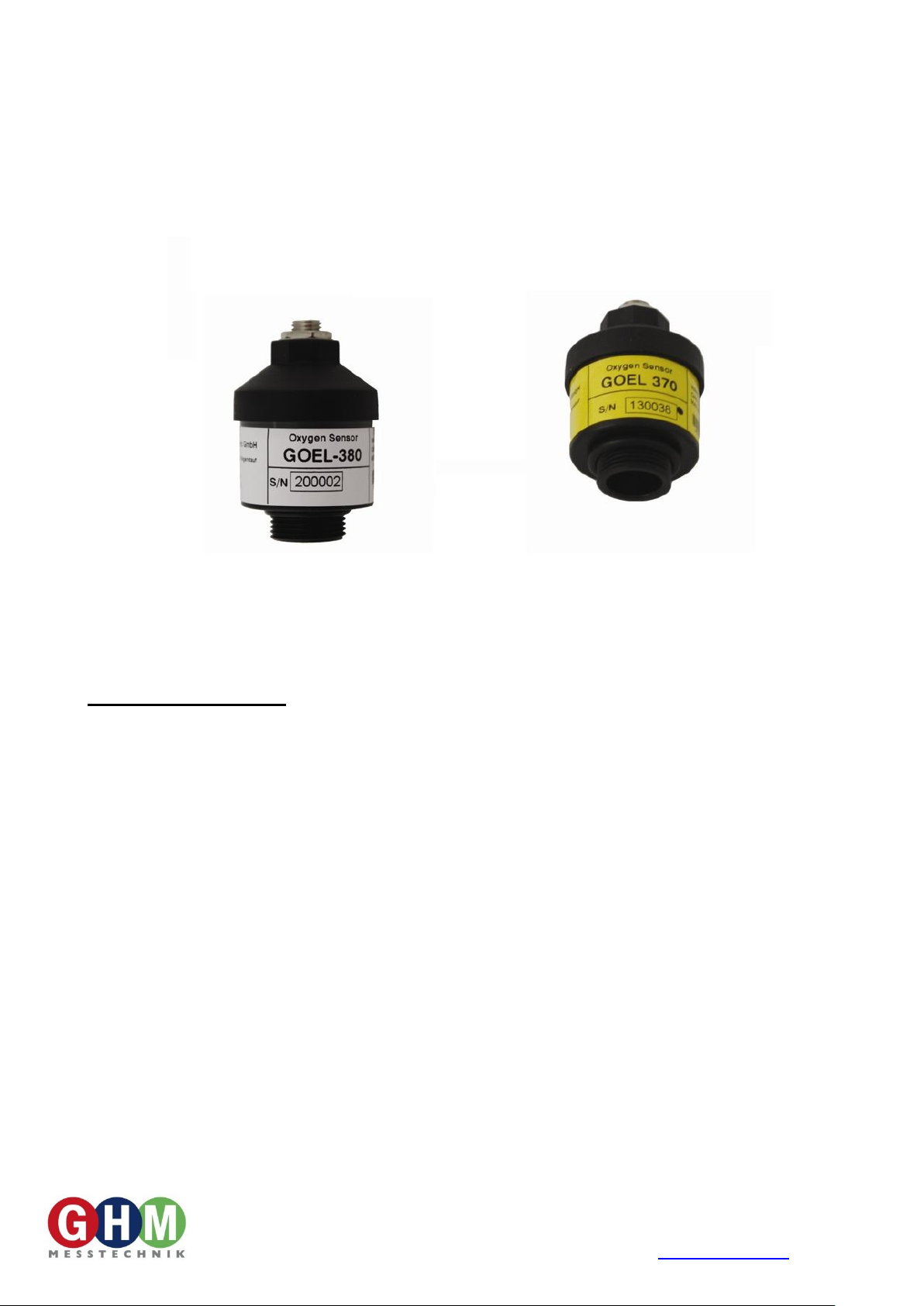
GOEL 370, GOEL 380
Atmospheric Oxygen Sensor - Replacement
General information:
GOEL 370 (acidic electrolyte): Specialized sensor for diving application e.g. measuring Nitrox. Construction is
optimized to this application, especially during professional usage in harsh environment the higher price will pay.
Also suitable to measure oxygen-concentration in air or other gases with a high CO2-content or even in a CO2atmosphere. The acid electrolyte guarantees that the sensor could not be influenced by CO2.
GOEL 380 (basic electrolyte): Sensor for low oxygen concentration e.g. controlled atmosphere. Without larger
CO2 concentration *).
*) The GOEL 380 (and formerly the GOEL 369) is designed to measure oxygen-concentration in air or other gases
without larger CO2 concentration. Higher CO2-concentration reduces the life-time of the sensor.
Short-time exposition of up to 10% CO2 is not problematic (for example 15 minutes. up to 10 times per day) for
the GOEL 380 (e.g. exhaust measuring). If there is measured more often with elevated CO2-concentration or at
CO2-concentrations above 10%, the exposition time has to be kept as short as possible and sufficient measuring
breaks should be made.
Note: If the sensor is not exposed to free air during measuring pauses, the connected tubes etc. have to be
flushed with clean air or nitrogen.
Z11.0.1X.6C-15 page 2 of 4
General information about the oxygen sensors
I.) Lifetime: At the end of life time the sensor signal drops relatively fast.
The electrode evaluation in % therefore just can be used for orientation. An evaluation of 70%
does not mean that 70% of life time are remaining, but 70% of the reference signal are available,
which happens normally at the end of life time.
Note: The electrode evaluation is updated by the instrument every time, when the calibration of the sensor was
performed successfully. (please also see the referring manual of the instrument)
The nominal life time can be shortened significantly by usage. Influencing factors are:
- Storage- / Operation temperature
- Humidity of measured gas: If permanently used with dry gases (technical gases, bottled gas) the life time
decreases considerably.
It helps, if the sensor is brought to normal humid ambient air in measuring breaks (“flush” system with fresh air).
II.) Operating position: The optimum operation position is with the sensor inlet pointing downwards,
maximum differential pressure to ambient is 250 mbar.
III.) Measuring precision: The measuring precision can be influenced by:
- Liquids at the sensor inlet. Rinse the inlet and dry with lint-free cloth.
Attention: avoid liquids of any kind at the contacts
- Gas and sensor temperature have to be at same level. Best precision, when calibrated at measuring
temperature.
- Pressure fluctuations: The sensor is originally a partial pressure sensor, i.e. changes in the absolute pressure
are influencing the measuring result directly proportional. A pressure change of 1% will cause a additional
measuring error of 1%!
For optimum precision calibrate at the same conditions at which You want to measure.
Safety requirements:
This device has been designed and tested in accordance with the safety regulations for electronic devices.
However, its trouble-free operation and reliability cannot be guaranteed unless the standard safety measures and
special safety advises given in this manual will be adhered to when using the device.
1. Trouble-free operation and reliability of the device can only be guaranteed if the device is not subjected to any
other climatic conditions than those stated under "Specification".
2. If the device is transported from a cold to a warm environment condensation may result in a failure of the
device. In such a case make sure the device temperature has adjusted to the ambient temperature before
trying a new start-up.
3. If there is a risk whatsoever involved in running it, the unit has to be switched off immediately and to be
marked accordingly to avoid re-starting.
Operator safety may be at risk if:
- there is visible damage to the device.
- the device is not working as specified.
- the device has been stored under unsuitable conditions for a longer time.
In case of doubt, please return device to manufacturer for repair or maintenance.
4. Warning: do not use these product as safety or emergency stop devices, or in any other application where
failure of the product could result in personal injury.
Failure to comply with these instructions could result in death or serious injury
5. Caution, acid! The sensor contains KOH (G___ 380) or acid (G___ 370).
KOH and acid can cause severe chemical burns!
If leaking, avoid contact!
If there was contact:
• to skin: Flush contacted area with large amounts of water for several minutes.
• to clothing: remove contaminated clothing.
• to eyes: Flush with large amounts of water for several minutes,
obtain medical treatment.
After swallowing:
• give large volumes of water. DO NOT induce vomiting!
• Obtain medical treatment.

Z11.0.1X.6C-15 page 3 of 4
Installation Instructions GGO-case:
a.) Dismantling of sensors
- unscrew cable buckling protection and push it upwards the
cable.
(loosen the cable in the remaining buckling protection part at
the rubber sealing gasket).
- unscrew both case parts.
- push case part at cable side upwards the cable and disconnect the sensor connector.
- unscrew the sensor carefully e.g. by means of suitable nippers.
b.) Assembly of new sensors
- remove new sensor element from packing.
- check exact position of sealing O-ring on the thread
- screw the sensor element carefully into the corresponding half of the case and tighten slightly e.g. by means of
nippers.
Attention: do not use force! Case can be destroyed by this!
- reconnect sensor plug to sensor element.
- screw on the second half of the case and the buckling protection.
Installation Instructions GOO-case:
a.) Dismantling of sensors
- unscrew cable buckling protection and push it upwards the
cable.
(loosen the cable in the remaining buckling protection part at
the rubber sealing gasket).
- unscrew lock screws if existing.
- unscrew both case parts.
- push case part at cable side upwards the cable and disconnect the sensor connector.
- unscrew the sensor-element carefully.
b.) Assembly of new sensors
- remove new sensor element from packing.
- check exact position of sealing ring on the thread
- screw the sensor element carefully into the corresponding half of the case and tighten slightly.
- reconnect sensor plug to sensor element.
- screw on the second half of the case and lock screws (if existing).
- screw on the buckling protection.
Installation Instructions GOX 100 sensor case:
- disconnect the sensor connector
- open screw cap, memorize the positions of the rubber rings
- remove the sensor from case
- remove new sensor element from packing.
- remove O-ring from new sensor (not needed)
- Place new sensor in case, considering the rubber rings
- Close screw cap, reconnect
Disposal of sensor element:
The sensor contains lead and caustic electrolyte. Dispose as special waste.
According to the ElektroG (law for bringing into market, the return and the environmentally friendly disposal
of electronic equipment) we accept the return of this sensors, please send it directly to us (adequately
stamped). We will dispose it appropriately and environmentally friendly.

Z11.0.1X.6C-15 page 4 of 4
GOEL 380
GOEL 370
Obsolete:
GOEL 369 S
Obsolete:
GOEL 369
oxygen partial pressure sensor
Application:
Low Oxygen
concentrations
Diving,
CO2 containing
gases
CO2 containing
gases
standard
Specific features
For low O2
concentration
Fast response
stronger membrane:
enhanced life time
and more robust
against pressure
changes
coated electronics:
Corrosion protection;
Less dependence on
operating position
better temperature
compensation
Acidic
electrolyte for
application with
significant CO2
levels
Measuring ranges:
O2 partial pressure:
0 ... 300 hPa
0 ... 1100 hPa
0 ... 300 hPa
0 ... 1100 hPa
O2 Concentration:
0.0 ... 25.0 %
0.0 ... 100.0 %
0.0 ... 25.0 %
0.0 ... 100.0 %
Sensor signal: 7 - 13 mV
(dry air, 1013 hPa, 25°C)
9 - 13 mV
7 - 13 mV
9 - 13.5 mV
7 - 13 mV
Electrolyte:
basic electrolyte
acidic electrolyte
acidic electrolyte
basic electrolyte
Response time:
(temperature depending)
90% in < 5s
90% in < 10s
90% in <15s
90% in < 5s
Cross sensitivities
Signal of <0.1 %
15% CO
2
in N2,
10% CO in N2,
3000ppm NO in N2,
3000ppm C3H8 in N2,
500ppm H2S in N
2
,
500ppm SO2 in N
2
,
1000ppm Benzene in N2
None to He, H2 and CO
Signal of <0,002 % O2
100% CO2,
100% CO,
3000ppm NO in N2,
100% C3H8,
2000ppm H2S in N2,
2000ppm SO2 in N2,
1000ppm Benzene in
N2,
1000ppm H2 in N
2
Signal von <0.1 %
15% CO
2
in N2,
10% CO in N2,
3000ppm NO in N2,
3000ppm C3H8 in N2,
500ppm H2S in N
2
,
500ppm SO2 in N
2
,
1000ppm Benzene
in N
2
Accuracy:
(with dry air, 1013 hPa, 25°C))
< 2 % O2
< 25 % O2
> 25 % O2
± 0.1 % O2
± 0.5 % O2
not specified
± 0.2 % O2
± 0.5 % O2
± 0.5 % O2
± 0.2 % O2
± 0.5 % O2
not specified
± 0.2 % O2
± 0.5 % O2
± 1.0 % O2
Normal sensor life
approx. 2 years at
standard conditions
approx. 4 years at
standard conditions
approx. 2 years at
standard conditions
approx. 2 years at
standard conditions
Ambient pressure:
0.5 to 2.0 bar abs.
Over-/under pressure:
max. 0.25 bar (pressure difference sensor membrane to ambient – sensor screwed-in)
Warranty period:
12 months (assuming appropriate usage according to the manual)
Connection:
3.5mm mono type plug
Working temperature:
0 to +50 °C
0 to +45 °C
0 to +50 °C
Relative humidity:
0 to +95 %RH (not condensing)
Storage temperature:
-15 to +60°C
housing dimensions:
approx. Ø 30 x 44 mm
Weight:
approx. 28 g
Specification
 Loading...