

Greenmaster MOMENTUM T7 User Manual

MOMENTUM T7 TREADMI LL
USER MANUAL

2 M OMENTUM T7 TREADMILL
PRECAUTIONS
For future service or related questions:
Please staple your receipt and/or write in the name and phone number of t he retail store where you purchas ed y our treadmill.
Nam e: ______________________________ Phone Number: ___________________ Rec eipt: ______________________
Precautions:
WARNING: To reduce the risk of burns , fire, elec t ric shock, or injury to persons, read the f ollowing import ant prec aut ions and
information before operat ing the t readmill. I t is the respons ibility of the owner t o ensure that all us ers of t his t readm ill are
adequately informed of all warnings and prec aut ions.
• Us e the t readm ill only as described in t his m anual.
• Place on a level surfac e, with 6 feet (2 m ) of c learanc e behind it. Do not plac e the treadm ill on any surface t hat blocks air
openings. To prot ect the f loor or carpet f rom damage, place a mat under t he treadmill.
• When c hoosing a loc ation for the t readm ill be s ure the loc at ion and posit ion permit access to a plug.
• Keep the treadmill indoors, away f rom m oisture and dust. D o not put the t readm ill in a garage or covered patio, or near
water.
• Do not operate the t readmill where aeros ol products are us ed or where oxygen is being administered.
• Keep children under the age of 12 and pet s away f rom the treadmill at all times.
• The treadmill should not be used by pers ons weighing m ore than 400lbs.
• Nev er allow m ore than one person on the treadmill at a t im e.
• Wear appropriat e exerc is e clothing when us ing the treadm ill. D o not wear loose c lothing that could becom e caught in t he
treadm ill. Athletic support clothes are recommended for both men and wom en. Always wear athletic shoes. Nev er use the
treadm ill with bare feet, wearing only stockings, or in sandals.
• When c onnecting the power cord, plug the power c ord into a grounded c ircuit. No other applianc e should be on t he sam e
circuit.
• Alway s straddle t he belt and allow it t o start moving bef ore stepping onto the belt.
• Alway s examine y our treadmill before us ing to ens ure all part s are in working order.
• Allow the belt to f ully st op before dismount ing.
• Nev er insert any object or body parts into any opening.
• Follow the saf ety information in regards to plugging in y our treadmill.
• Keep the power c ord away f rom t he incline wheels and do not run the power c ord underneath your treadmill. D o not
operate t he treadm ill with a dam aged or frayed power cord.
• Always unplug t he treadmill before c leaning and/or servicing. Serv ice to your t readm ill should only be performed by an
authorized serv ice repres ent ative, unles s authorized and/or instructed by t he manufacturer. F ailure to follow these
inst ructions will void the treadmill warranty .
• N ev er leave t he treadmill unattended while it is running.
www.greenmasterfitness.com.tw
3
PO WER REQ UIREMENTS
Power Requirements :
IMPROPER CONNECTION OF THE EQUIPMENT GROUNDING C ONN EC TOR CAN R ESU LT IN A R I SK OF AN ELECTRI C
SHOC K. C H ECK WI TH A QUALIFI ED ELECTRICI AN OR SERVICE MAN IF YOU ARE IN DOU BT AS TO W H ETHER THE
PRODUCT IS PROPERLY GROUNDED. DO NOT MODIFY THE PLUG PROVIDED WITH THE PRODUCT, IF IT WILL NOT FIT
THE OUTLET; HAVE A PROPER OUTLET INSTALLED BY A QUALIFI ED ELECTRICI AN.
This treadm ill can be seriously damaged by s udden voltage changes in your home’s electrical power. Voltage spik es, surges and
noise int erference can res ult from weather c ondit ions or f rom other appliances being t urned on or off . To reduce t he possibility of
treadm ill damage, alway s use a s urge protector (not included) with y our treadmill.
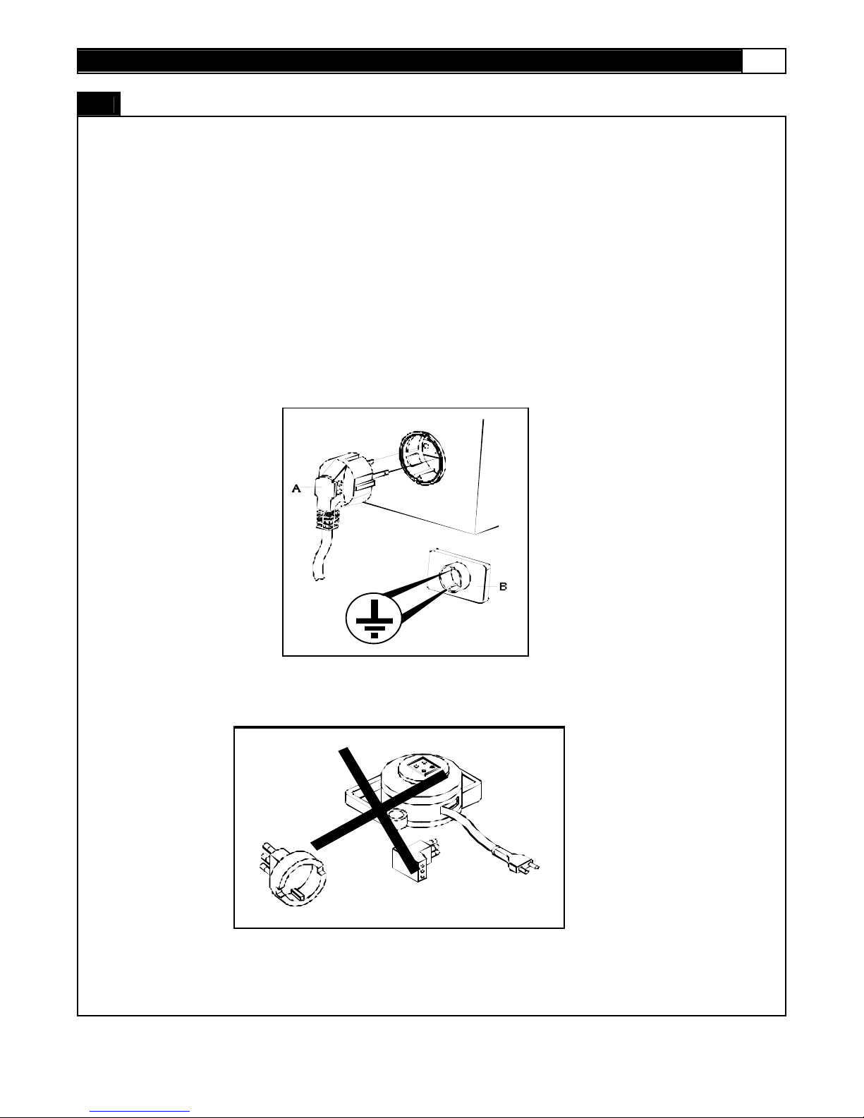
This treadm ill mus t be grounded to reduce t he risk of elec t rical shock. Grounding prov ides a path of least resistance for electric
current , should the t readmill malf unction. This treadmill comes with an electric al cord hav ing an equipment -grounding conduc t or
and a grounding plug. Alway s plug t he power c ord into a s urge protect or, and plug the surge protector int o an appropriate outlet
that is properly installed and grounded in accordance with all local c odes and ordinances.
This product is for use on a nom inal 230-volt circuit, and has a grounding plug t hat looks like the plug illustrated in the drawing
below.

4 M OMENTUM T7 TREADMILL
PREASSEMBLY
Open the boxes:
Y ou are now ready to open t he boxes of y our new equipm ent. Make sure t o invent ory all of the parts that are inc luded in t he boxes.
Chec k the Cont ents Checklist and Hardware C om parison Chart f or a full count of t he number of parts included for t his product to be
ass em bled properly.
Ga t he r yo ur to ols :
Before st art ing the assembly of your unit, make s ure that you hav e gathered all the necessary tools y ou may require to as s emble
the unit properly . Having all of t he necess ary equipm ent at hand will s av e time and mak e the ass embly quick and hassle-f ree.
Cl ear your wor k area:
Make sure that you have c leared away a large enough s pace to properly as s emble the unit. Mak e sure the spac e is free from
anyt hing that may cause injury during assembly . Aft er the unit is f ully assembled, mak e sure t here is a c omfort able amount of free
area around the unit f or unobstructed operation.
Invite a friend:
Some of the ass em bly st eps m ay require heavy lift ing. It is recom m ended that you obt ain the ass istance of another person when
ass em bling this product.
User Weight Limitation:
Please not e that there is a weight limitation for this product . If you weig h more than 400lbs. it i s not recommended th at you
use this product. Seriou s injur y may occur if the user’s wei ght exceeds the limit sh o wn her e. This product is not intended
to s upport us ers whose weight exceeds this limit.

www.greenmasterfitness.com.tw
5
CO NTENTS CHECKLIST
C a rt on co nt e nt s :
For y our conv enienc e, we hav e identif ied the cont ents of t he shipping cart on. Pleas e check to mak e sure you have all of the
com ponents before as s embly. This chart is prov ided to help you identify the c om ponents used in t he assembly of this produc t.
No. Description Qty.
A
Main Frame Assembly
1
B Front Handlebar Assembly 1
C Handlebar Assembly 2
3 Cons ole Support Tube 1
10 Handlebar R ear End Cap - Lef t # 1 1
11 Handlebar R ear End Cap - Lef t # 2 1
12 Handlebar R ear End Cap - Right # 1 1
13 Handlebar R ear End Cap - Right # 2 1
27 Upright Support Tube 2
41 Upright Plastic Shroud Left #1 1
42 Upright Plastic Shroud Left #2 1
43 Upright Plastic Shroud R ight #2 1
44 Upright Plastic Shroud R ight #1 1
6 M OMENTUM T7 TREADMILL
H ARDWARE COMPARISON CHART
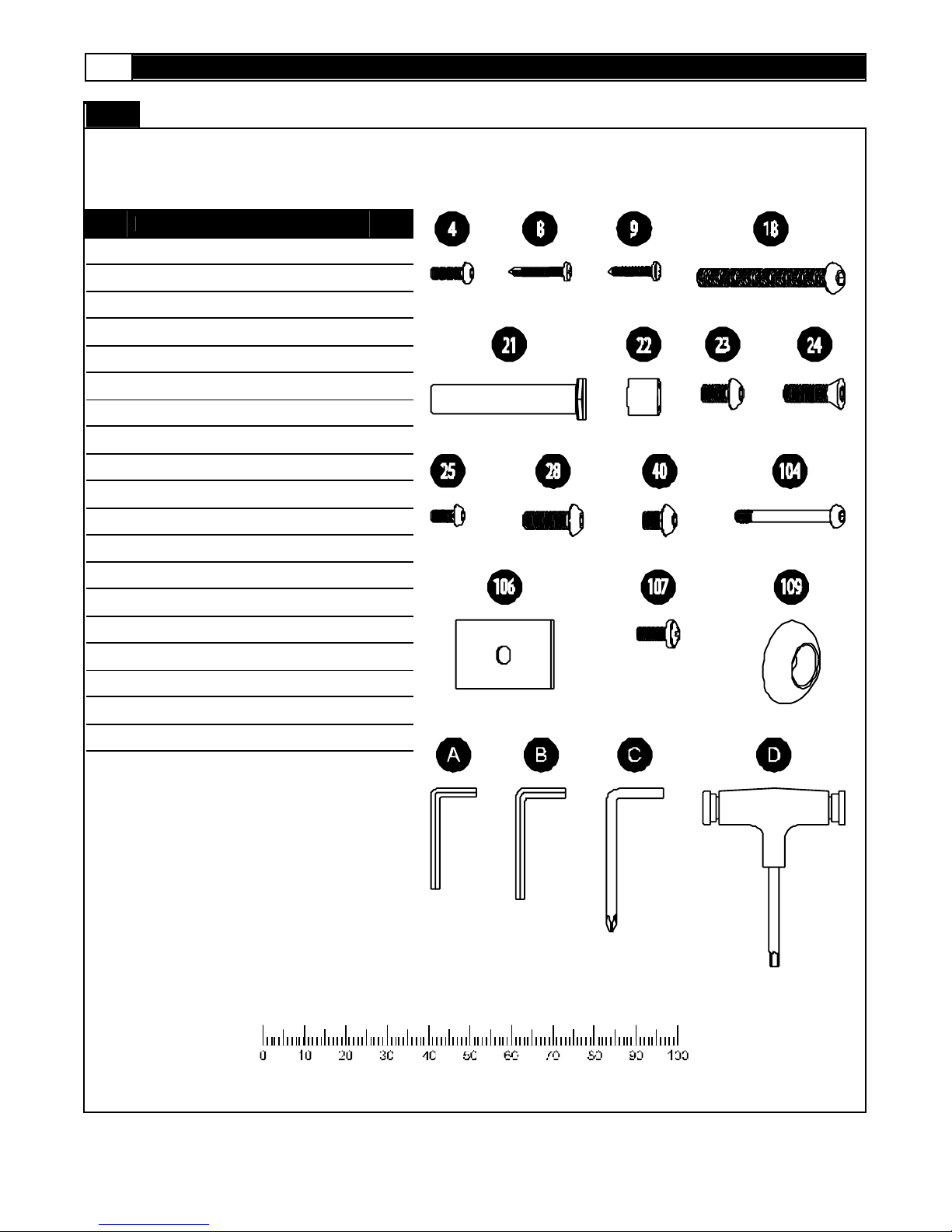
Hardware chart:
For y our conv enienc e, we hav e identif ied the hardware us ed in the assembly of this produc t. This chart is prov ided to help y ou
identify t hose it ems that may be unfamiliar to you.
No. Description Qty.
4
M6 x 20mm Allen H ead Bolt
2
8 #8 x 19mm Screw 20
9 #8 x 25mm Screw 8
18 M8 x 95mm Sc rew 2
21 1/2" x 68mm Bolt 2
22 Plastic Spacer 4
23 M8 x 25mm Allen H ead Bolt 2
24 M10 x 20mm Allen H ead Bolt 4
25 M8 x 20mm Allen H ead Bolt 2
28 M8 x 15mm Allen H ead Bolt 6
40 M8 x 10mm Allen H ead Bolt 4
104 Console Screw 2
106 Upright Cover 2
107 M6 x 15mm Screw 2
109 Metal Cap 2
A 4mm Wrench 1
B 5mm Wrench 1
C Phillips H ead Wrenc h 1
D 6mm Wrench 1
MILLIMETERS

www.greenmasterfitness.com.tw
7
PARTS LIST
No. Description Qty. Or d er No. No. Description Qty. Or d er No.
1 Com put er 1 T7 - 001 35 Cus hion 4 T7 - 035
2 Key pad 1 T7 - 002 36 M6 x 13mm Was her 2 T7 - 036
3 Cons ole Support Tube 1 T7 - 003 37 #8 x 15mm Screw 38 T7 - 037
4 M6 x 20mm Allen Head Bolt 2 T7 - 004 38 Cons ole Housing - Bot t om 1 T7 - 038
5 C ons ole Support Tube 1 T7 - 005 39 D ec k Fixing Tube 1 T7 - 039
6 N/ A 40 M8 x 10mm Allen Head Bolt 4 T7 - 040
7 Plast ic Fixing I ns ert 8 T7 - 007 41 Upright Plastic Shroud Lef t #1 1 T7 - 041
8 #8 x 19mm Screw 24 T7 - 008 42 U pright Plastic Shroud Left #2 1 T7 - 042
9 #8 x 25mm Screw 8 T7 - 009 43 Upright Plastic Shroud R ight #2 1 T7 - 043
10 H andlebar R ear End Cap - Left # 1 1 T7 - 010 44 Upright Plastic Shroud R ight #1 1 T7 - 044
11 H andlebar R ear End Cap - Left # 2 1 T7 - 011 45 Side Cov er - Left 1 T7 - 045
12
Handlebar R ear End Cap - Right #
1
1 T7 - 012 46 Side Cov er - R ight 1 T7 - 046
13
Handlebar R ear End Cap - Right #
2
1 T7 - 013 47 Power Switc h Set 1 T7 - 047
14 H andlebar Grip 2 T7 - 014 48 M5 x 10mm Screw 2 T7 - 048
15 H andlebar 2 T7 - 015 49 Motor Hood 1 T7 - 049
16 H and Puls e Sensor 2 T7 - 016 50 Top Maintenance C over 1 T7 - 050
17 C ons ole Housing - Upper 1 T7 - 017 51 #8 x 50mm Screw 2 T7 - 051
18 M8 x 95mm Screw 2 T7 - 018 52 Aluminum Side Rail 2 T7 - 052
19 U pright - Left 1 T7 - 019 53 Running Belt 1 T7 - 053
20 U pright - Right 1 T7 - 020 54 Running D eck Rear Cover 1 T7 - 054
21 1/ 2" x 68mm Bolt 2 T7 - 021 55 Rear F oot Platf orm 1 T7 - 055
22 Plas t ic Spacer 4 T7 - 022 56 Rubber Spac er - Lef t 1 T7 - 056
23 M8 x 25mm Allen Head Bolt 2 T7 - 023 57 Rubber Spac er - Right 1 T7 - 057
24 M10 x 20mm Allen Head Bolt 4 T7 - 024 58 Running D eck 1 T7 - 058
25 M8 x 20mm Allen Head Bolt 2 T7 - 025 59 Dec k Rubber Cus hion 10 T7 - 059
26 Adjus t able Cy linder 2 T7 - 026 60 M10 x 35mm Bolt 1 T7 - 060
27 U pright Support Tube 2 T7 - 027 61 M5 x 15mm Screw 2 T7 - 061
28 M8 x 15mm Allen Head Bolt 16 T7 - 028 62 C lip 2 T7 - 062
29 M6 x 55mm Allen Head Bolt 2 T7 - 029 63 Elevation Motor 1 T7 - 063
30 M14 x 113mm Bolt 2 T7 - 030 64 M10 Ny lon Nut 2 T7 - 064
31 Bus hing 4 T7 - 031 65 Tension Wheel 1 T7 - 065
32 St abilizer 2 T7 - 032 66 Front Vent C ov er 1 T7 - 066
33 Bas e F rame 1 T7 - 033 67 Rear Vent Cover 1 T7 - 067
34 R unning D eck Fix ed Tube Sleev e 2 T7 - 034 68 Logo Light Bracket 1 T7 - 068

8 M OMENTUM T7 TREADMILL
PARTS LIST
No. Description Qty. Or d er No. No. Description Qty. Or d er No.
69 D riv ing Motor 1 T7 - 069 103 #8 x 35mm Screw 4 T7 - 103
70 R oller C arbon Brush 1 T7 - 070 104 Cons ole Screw 2 T7 - 104
71 Motor H older 1 T7 - 071 105 Handlebar F ixing Plate 2 T7 - 105
72 Motor H older Adjustment 1 T7 - 072 106 U pright Cover 2 T7 - 106
73 M10 x 136mm Bolt 1 T7 - 073 107 M6 x 15mm Screw 2 T7 - 107
74 M10 x 63mm Bolt 1 T7 - 074 108 Front Handle bar 1 T7 - 108
75 Motor D riv e Belt 1 T7 - 075 109 Metal Cap 3 T7 - 109
76 Tension W heel Bracket 1 T7 - 076 110 M8 x 45mm Bolt 12 T7 - 110
77 Transfer Board 1 T7 - 077 111 Emergency St op 1 T7 - 111
78 F ront Roller 1 T7 - 078 112 Hand Puls e Sensor Wire - Upper 2 T7 - 112
79 F ront Roller Shaf t 1 T7 - 079 113 Side Rail Guide Light Board 1 T7 - 113
80 D ec k Frame 1 T7 - 080 114 N/ A
81 Micro Switc h 1 T7 - 081 115 N/ A
82 M8 x 70mm Bolt 3 T7 - 082 116 Handle Bar Plastic Bushing 2 T7 - 116
83 8 x 16 x T2.0 Washer 13 T7 - 083 117 Motor Cont rol Board 1 T7 - 117
84 Motor H ood Side Cov er - Left 1 T7 - 084 118 Motor Cont rol Board F an 1 T7 - 118
85 Motor H ood Side Cov er - Right 1 T7 - 085 119 Main Transf ormer 1 T7 - 119
86 F ram e Side Cov er - Left 1 T7 - 086 120 N/A
87 F ram e Side Cov er - Right 1 T7 - 087 121 N/ A
88 Plas t ic Clamp - Top 2 T7 - 088 122 N/A
89 Plas t ic Clamp - Bottom 2 T7 - 089 123 Motor Cont rol Board C over 1 T7 - 123
90 Brac k et 2 T7 - 090 124 Motor Cont rol Board R adiat or 1 T7 - 124
91 M8 x 25mm Screw 4 T7 - 091 125 Rear F rame 1 T7 - 125
92 R ear R oller 1 T7 - 092 126 Foot Platf orm Support F ram e 1 T7 - 126
93 R ear R oller Shaft 1 T7 - 093 127 Dec k Frame Side Cover - Left #2 1 T7 - 127
94 M8 x 43mm Bolt 2 T7 - 094 128 Dec k Frame Side Cover - R ight #2 1 T7 - 128
95 M8 Ny lon Nut 12 T7 - 095 129 10 x 16 Washer 1 T7 - 129
96 D ec k Wheel 2 T7 - 096 130 Side R ail Guide Light 2 T7 - 130
97 Rubber Dot
1
SET
T7 - 097
98 D ec k Wheel Brack et 2 T7 - 098
99
Elevation Support Tube Side Cover
- Lef t
1 T7 - 099
100
Elevation Support Tube Side
Cov er - Right
1 T7 - 100
101 Elevat ion Support Tube 1 T7 - 101
102 Motor Belly Pan 1 T7 - 102
www.greenmasterfitness.com.tw
9
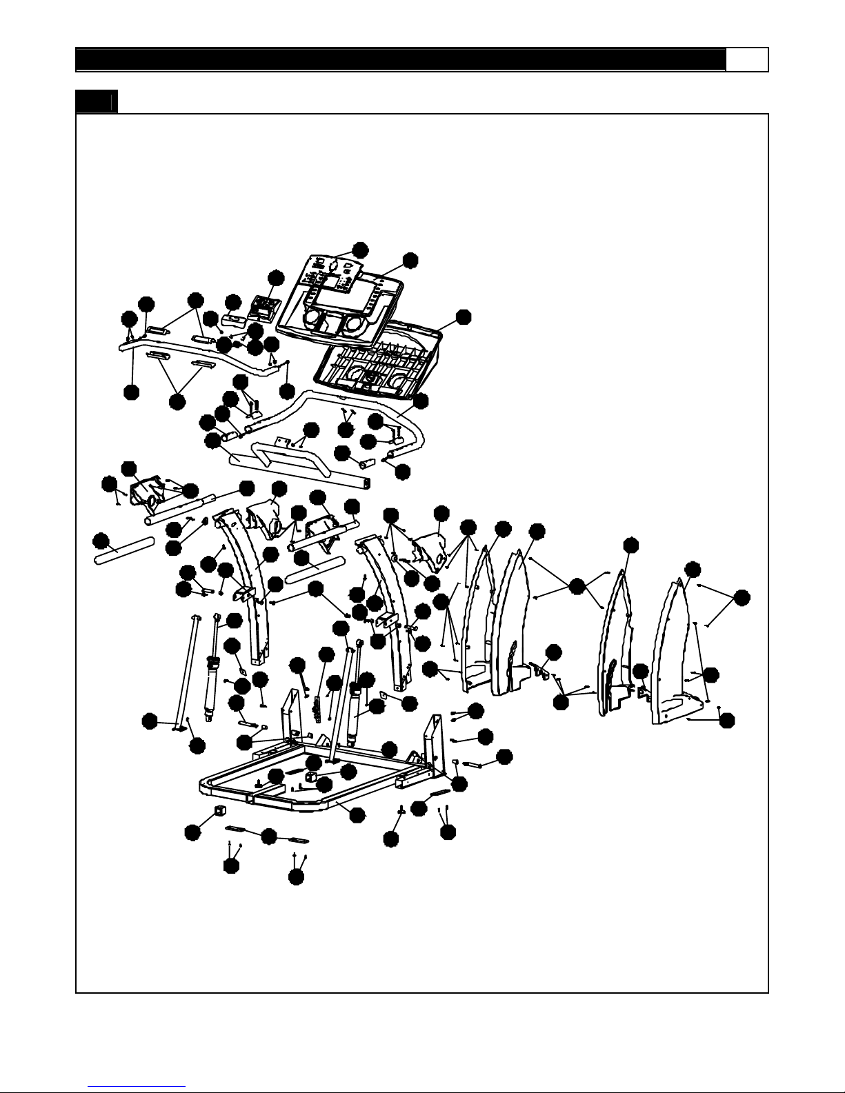
PART S DIA GRAM
A MAJORI T Y OF THE PAR TS SHOWN HERE HAVE BEEN PREASSEMBL ED AT TH E F ACTORY.
2
16
16
8
44
5
110
110
20
25
13
18
8
42
41
43
109
9
9
46
8
21
24
106
28
30
45
31
8
9
8
8
3
7
3
5
7
15
15 11
3
105
108
16
2
1
12
17
14
8
25
109
10
8
105
16
22
7
19
21
18
14
24
27
47
106
28
24
26
24
22
28
30
26
33
32
3
7
27
28
107
107
29
48
3
5
31
34
37
37
35
23
34
32
116
116
4
112
112
104
38
111
112
113
114
115 40
40

10 MOMENTUM T7 TREADMILL
PART S DIA GRAM
A MAJORI T Y OF THE PAR TS SHOWN HERE HAVE BEEN PREASSEMBL ED AT TH E F ACTORY.
www.greenmasterfitness.com.tw
11
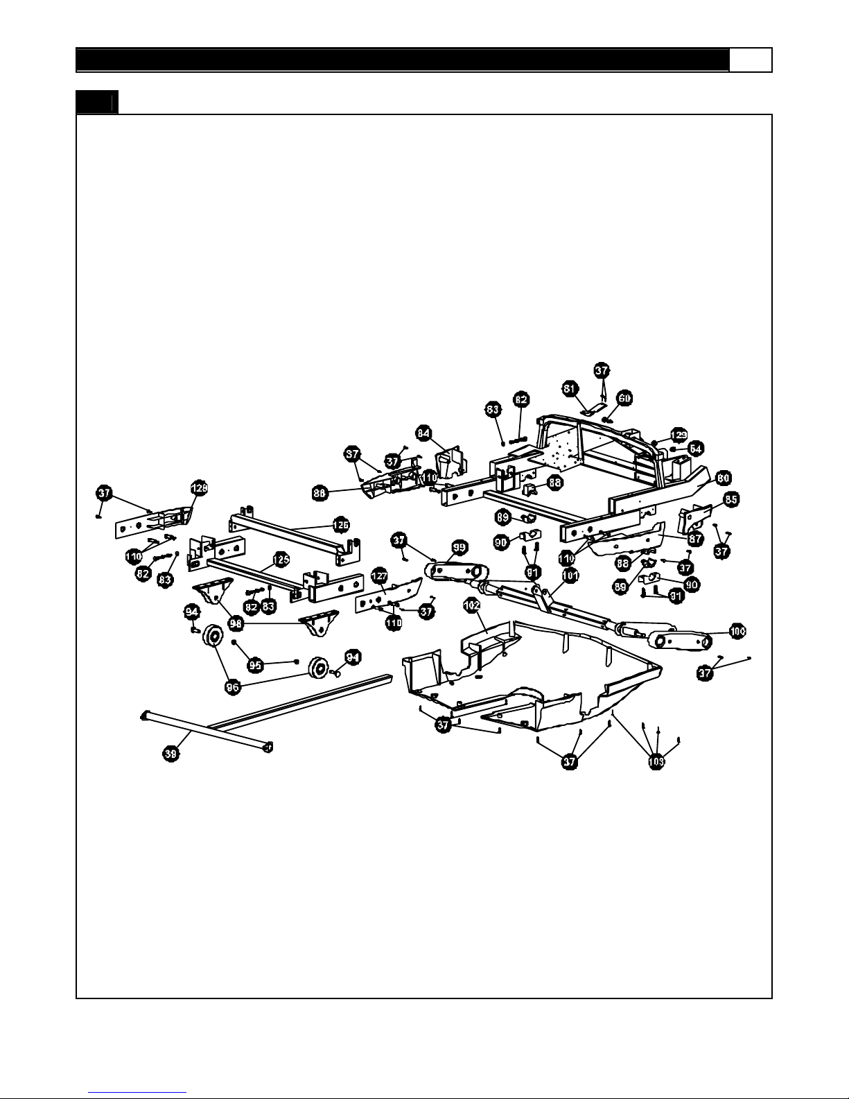
PART S DIA GRAM
A MAJORI T Y OF THE PAR TS SHOWN HERE HAVE BEEN PREASSEMBL ED AT TH E F ACTORY.
12 MOMENTUM T7 TREADMILL
ASSEMBLY
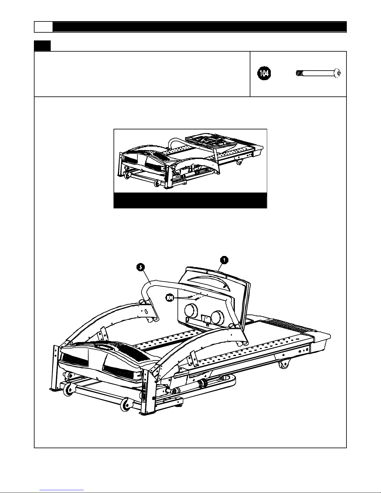
STEP 1:
R emove your treadmill from the cart on and place it on the f loor in an open area as shown
in FI G. 1.
Secure t he Com put er (1) t o the C ons ole Tube (5) using two Console Sc rews (104).
x2
FIG. 1
 Loading...