

Page 1
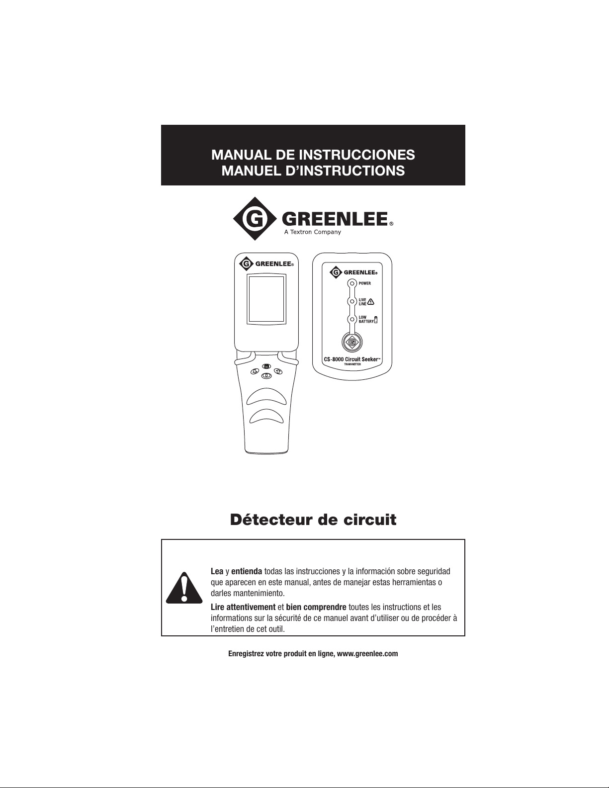
Circuit Tracer
Rastreador de circuito
Détecteur de circuit
52046568 REV 2 © 2009 Greenlee Textron Inc. 6/09
INSTRUCTION MANUAL
MANUAL DE INSTRUCCIONES
MANUEL D’INSTRUCTIONS
Read and understand all of the instructions and safety information in this
manual before operating or servicing this tool.
Lea y entienda todas las instrucciones y la información sobre seguridad
que aparecen en este manual, antes de manejar estas herramientas o
darles mantenimiento.
Lire attentivement et bien comprendre toutes les instructions et les
informations sur la sécurité de ce manuel avant d’utiliser ou de procéder à
l’entretien de cet outil.
Register this product at www.greenlee.com / Registre este producto en www.greenlee.com
Enregistrez votre produit en ligne, www.greenlee.com
CS-8000
Circuit Seeker
™
Find Quality Products Online at: [email protected]
www.GlobalTestSupply.com
Page 2
2
Description
The Greenlee CS-8000 Circuit Seeker™ Circuit Tracer identifies and traces either live or
unenergized circuits. It also locates faults or opens in a circuit, identifies specific circuit breakers,
and traces circuits including those shorted to ground. The CS-8000 consists of a receiver,
a transmitter, and accessories for connecting the transmitter to the circuit being traced or
identified.
The CS-8000 receiver incorporates patented, non-directional signal detection circuitry. It is not
necessary to rotate the receiver when following the path of the traced object.
Safety
Safety is essential in the use and maintenance of Greenlee tools and equipment. This instruction
manual and any markings on the tool provide information for avoiding hazards and unsafe
practices related to the use of this tool. Observe all of the safety information provided.
Purpose of This Manual
This instruction manual is intended to familiarize all personnel with the safe operation and
maintenance procedures for the Greenlee CS-8000.
Keep this manual available to all personnel.
Replacement manuals are available upon request at no charge at www.greenlee.com.
Do not discard this product or throw away!
For recycling information, go to www.greenlee.com.
All specifications are nominal and may change as design improvements occur. Greenlee Textron Inc.
shall not be liable for damages resulting from misapplication or misuse of its products.
® Registered: The color green for electrical test instruments is a registered trademark of
Greenlee Textron Inc.
Circuit Seeker is a trademark of Greenlee Textron Inc.
KEEP THIS MANUAL
Lifetime Limited Warranty
Greenlee Textron Inc. warrants to the original purchaser of these goods for use that these products
will be free from defects in workmanship and material for their useful life, excepting normal wear and
abuse. This warranty is subject to the same terms and conditions contained in Greenlee Textron Inc.’s
standard one-year limited warranty.
For all Test Instrument repairs, contact Customer Service at 800-435-0786 and request a Return
Authorization.
For items not covered under warranty (such as items dropped, abused, etc.), a repair cost quote is
available upon request.
Note: Prior to returning any test instrument, please check replaceable batteries or make sure the
battery is at full charge.
Find Quality Products Online at: [email protected]
www.GlobalTestSupply.com
Page 3

CS-8000
3
SAFETY ALERT SYMBOL
This symbol is used to call your attention to hazards or unsafe practices which could result
in an injury or property damage. The signal word, defined below, indicates the severity of the
hazard. The message after the signal word provides information for preventing or avoiding
the hazard.
Immediate hazards which, if not avoided, WILL result in severe injury or death.
Hazards which, if not avoided, COULD result in severe injury or death.
Hazards or unsafe practices which, if not avoided, MAY result in injury or property damage.
Read and understand this material before operating or servicing this
equipment. Failure to understand how to safely operate this tool could result
in an accident causing serious injury or death.
Electric shock hazard:
Contact with live circuits could result in severe injury or death.
Important Safety Information
Find Quality Products Online at: [email protected]
www.GlobalTestSupply.com
Page 4
4
Important Safety Information
Electric shock and fire hazard:
Do not expose this unit to rain or moisture.•
Do not use the unit if it is wet or damaged.•
Use test leads or accessories that are appropriate for the application. Refer to the category •
and voltage rating of the test lead or accessory.
Inspect the test leads or accessory before use. They must be clean and dry, and the •
insulation must be in good condition.
Use this unit for the manufacturer’s intended purpose only, as described in this manual. Any •
other use can impair the protection provided by the unit.
Failure to observe these warnings could result in severe injury or death.
Electric shock hazard:
The transmitter Live Line indication does not function if the batteries are dead or removed. •
Test on a known live circuit before use.
Do not apply more than the rated voltage between any two input terminals, or between any •
input terminal and earth ground.
Do not contact the test lead tips or any uninsulated portion of the accessory.•
Using this unit near equipment that generates electromagnetic interference can result in •
unstable or inaccurate readings.
Failure to observe these warnings could result in severe injury or death.
Electric shock hazard:
Do not operate with the case or battery compartment open.•
Before opening the case or battery compartment, remove the test leads from the circuit and •
shut off the unit.
Failure to observe these warnings could result in severe injury or death.
Electric shock hazard:
Do not attempt to repair this unit. It contains no user-serviceable parts.•
Do not expose the unit to extremes in temperature or high humidity. Refer to •
“Specifications.”
Failure to observe these precautions may result in injury and can damage the unit.
Find Quality Products Online at: [email protected]
www.GlobalTestSupply.com
Page 5
CS-8000
5
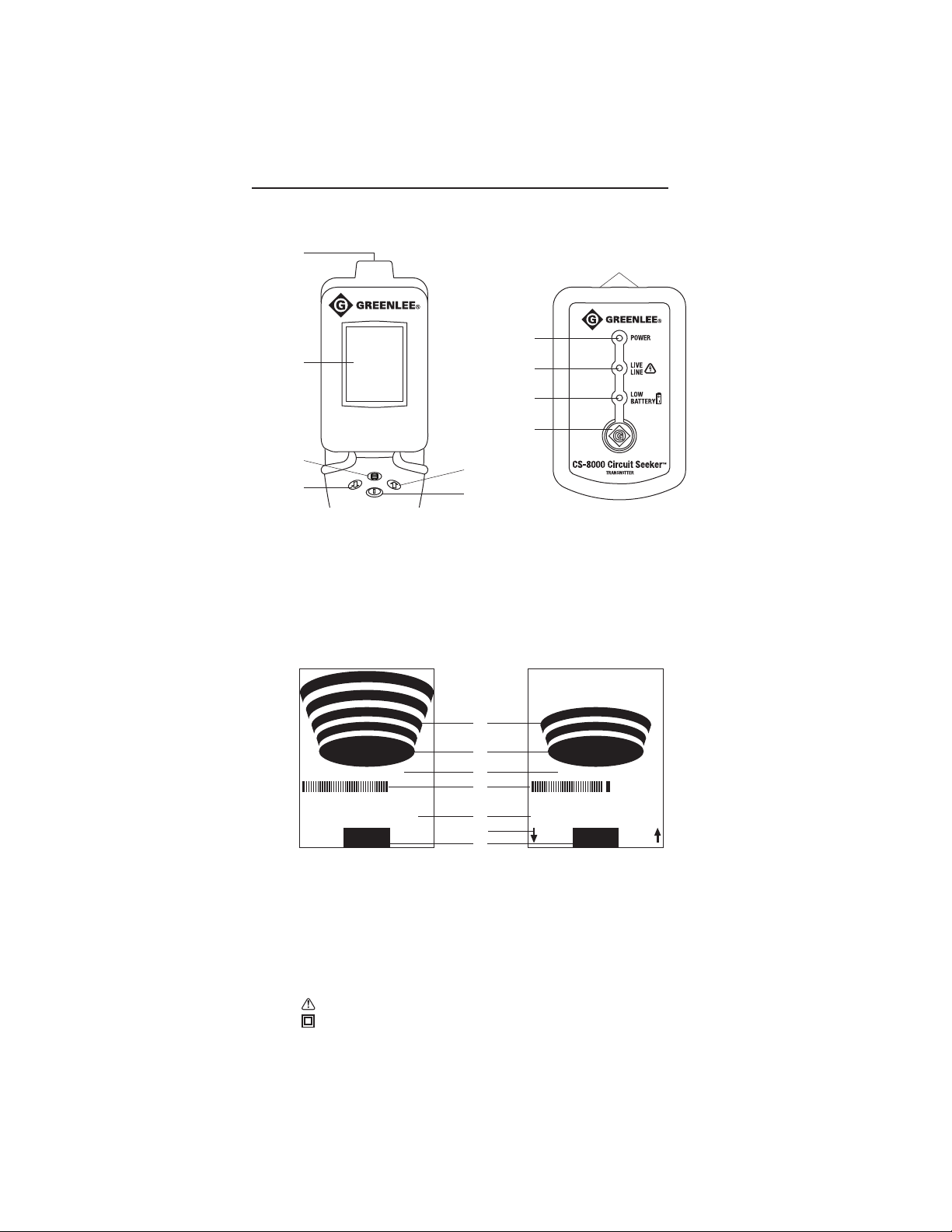
Identification
Display Icons
12. Relative Signal Strength
13. Transmitter Signal Indicator
14. Mode (Breaker–Search)
15. Absolute Signal Strength
2
4
3
1
8
9
10
11
7
5
6
SEARCH MODE
Signal Strength
AUTO GAIN
OPEN
SEARCH MODE
Signal Strength
MANUAL GAIN
LIVE
12
13
14
15
16
18
17
16. Gain Mode (Auto–Manual)
17. Signal adjustment arrows
(Manual Gain only)
18. Line Status (Live–Open)
Transmitter
7. Connectors (non-polarized)
8. Power LED
9. Live Line LED
10. Low Battery LED
11. Power pushbutton
Receiver
1. Sensing surface
2. Display
3. Mode Selector
4. Decrease Manual Gain
5. Increase Manual Gain
6. Power/Signal Reset pushbutton
Symbols on the Unit
Warning—Read the instruction manual
Double insulation
Find Quality Products Online at: [email protected]
www.GlobalTestSupply.com
Page 6

6
Features of the Transmitter
Power Button: Press and release to turn the transmitter on. Press and release to turn the
transmitter off.
Power LED: Indicates that the transmitter is turned on.
Live Line LED: This LED illuminates when the transmitter is connected to a voltage of at least
12 VAC or 5 VDC.
Low Battery LED: This LED illuminates when approximately one hour of battery life is remaining
under typical use conditions. When this LED flashes, the batteries are nearly exhausted. Replace
them immediately.
Automatic Power Off: The transmitter will turn off after four hours.
Features of the Receiver
The receiver is designed to be held in the user’s hand. The hand and body act as a ground plane
reference, which improves the sensitivity of the receiver. Without this ground plane reference, the
range of the receiver can be significantly reduced.
Transmitter Signal Indicator: This indicator is a solid blue oval when the receiver senses the
signal from the transmitter. Alternating segments of a red oval indicate there is no signal from the
transmitter, or the signal is too low to detect at the current gain setting.
Absolute Signal Strength bar graph: This displays the strength of the received signal. The red
bar indicates the maximum signal received since the unit was reset.
Relative Signal Strength indicators: These four arcs represent a magnified view of
the Absolute Signal Strength bar graph. All four arcs will be displayed when the signal is
approximately equal to the maximum signal received. Lower signal levels will display fewer arcs.
When the signal drops further, no arcs will be displayed. The magnification factors are different in
Breaker Mode and Search Mode, as explained below.
Gain Mode is Auto when the receiver is turned on. Manual Gain is selected by pressing either the
Increase Manual Gain h or Decrease Manual Gain i button on the receiver. Refer to the “Using
Gain Modes” section below for details of these modes.
Line Status is LIVE when the transmitter is connected to a circuit powered by at least 12 VAC or
5 VDC. Line Status is OPEN when the transmitter is connected to a deenergized line.
Power Button: Press and release to turn the receiver on. Press and hold to turn the receiver off.
This button also serves as Signal Reset. Press momentarily to reset the receiver gain to
maximum. To change from Manual Gain to Auto Gain, press and hold for about one second, and
then release. “AUTO GAIN” will appear on the display.
Mode Selector button toggles the receiver between Breaker Mode and Search Mode. The
receiver is in Breaker Mode when it is initially powered on.
In Breaker Mode, weaker signals are ignored. A higher magnification factor is used for the
Relative Signal Strength portion of the display. A smaller signal range is required to change the
display from one arc to four arcs. Small changes in signal strength can be easily observed. This
mode is usually best for identifying circuit breakers. It can also be useful for tracing circuits or
objects that are very close to the receiver, and for locating the exact location of a break or short
in a conductor.
In Search Mode, a wider range of signal strength is displayed. A lower magnification factor is
used for the Relative Signal Strength portion of the display. A larger signal range is required to
change the display from one arc to four arcs. This mode is usually best for locating and tracing
circuits, except when the traced object is very close to the receiver.
Using the Features
Find Quality Products Online at: [email protected]
www.GlobalTestSupply.com
Page 7

CS-8000
7
There is overlap between the gain ranges of the Breaker Mode and Search Mode. The
recommended mode usually gives the desired results. Some applications may be found where
the alternate mode is preferred.
Using Gain Modes
Automatic Gain is the default mode for the CS-8000 receiver. The receiver gain is initially set
to maximum. When the transmitter signal is detected, the gain is automatically decreased in
proportion to the signal strength. At the reduced gain, the largest detected signal does not result
in an overrange display. The detected signal is constantly monitored, and the gain is reduced
further if a stronger signal is detected. Gain is never increased in the Auto Gain mode. The actual
signal strength will decrease when tracing long conductors, or when the distance between the
receiver and conductor is increased. It is possible to lose the signal if the receiver is moved too
far from the actual path of the conductor. In these cases, momentarily press the Power/Signal
Reset button to return the gain to maximum. This will restore maximum signal strength on the
display and allow location of the true path of the conductor. This step may be repeated several
times when tracing a circuit.
Manual Gain is useful when the gain must be held constant, such as when making comparisons
between the signals on two different circuit breakers. It can also be used while tracing.
Varying signal strength sometimes requires frequent resetting of the Auto Gain, which can be
inconvenient.
To switch from Auto Gain to Manual Gain, press either the Increase Manual Gain h or Decrease
Manual Gain i button on the receiver. The Gain Mode indicator will change from “AUTO GAIN” to
“MANUAL GAIN.” The receiver gain will remain at its present value. A wide black segment on the
Absolute Signal Strength bar graph indicates the signal level that will produce four arcs on the
Relative Signal Strength display. Press the Increase Manual Gain h button to increase the signal
strength. Note that this will move the black bar to the left. Press the Decrease Manual Gain i
button to decrease the signal strength. Note that this will move the black bar to the right.
The CS-8000 Manual Gain feature requires several thousand steps to cover its full range. This
allows very precise control of the gain. To make large changes in the Manual Gain setting,
momentarily press the Power/Signal Reset button to align the Manual Gain value with the
current signal level. To establish a wide search window, momentarily press the Power/Signal
Reset button when the receiver is a distance away from the traced conductor. A greater distance
will produce a wider window. To establish a narrow search window, momentarily press the
Power/Signal Reset button when the receiver is close to the traced conductor.
Low Battery Indication: The receiver places “Low Battery” at the top of the LCD. The indication
appears when approximately one hour of battery life is remaining under typical use conditions.
The display backlight will dim to maximize the remaining battery life.
Automatic Power Off: The receiver will turn off after 30 minutes of inactivity. Activity means a
change in signal level or pressing of the Power/Signal Reset button. The backlight will turn off
after two minutes of inactivity. The backlight will automatically turn on again when a change in
the signal is detected, or if a button is pressed.
Using the Features (cont’d)
Find Quality Products Online at: [email protected]
www.GlobalTestSupply.com
Page 8

8
Theory of Operation
The CS-8000 transmitter is intended for connection to an electrical line (up to 750 volts) or
other metallic object. The transmitter signal consists of a controlled frequency with a specific
modulation and timing that is different for live and open circuits. This composite signal gives it a
specialized signature.
The transmitter signal generates a corresponding magnetic or electrostatic field signature around
the conductor being traced. This field signature is present the entire length of the conductor,
including breakers, fuses, switchgear, and transformers.
The CS-8000 receiver is tuned and programmed to pick up only the field signatures produced
by the transmitter. To be received, the signal must have this exact frequency, modulation, and
timing. This feature greatly reduces the possibility of interference from electrical noise, which is
often caused by lamps, appliances, fluorescent fixtures, or machinery that is on the same line.
Both the transmitter and the receiver are microprocessor-controlled for maximum ease of use
and accuracy.
Basic Operation
These instructions provide the user with a basic understanding of how the unit functions. These
tests are best performed at a desk or bench.
Transmitter
1. Push and release the Power button. The Power LED illuminates, indicating unit power and
signal being sent.
2. Plug the unit into any energized outlet. The Live Line LED also illuminates, indicating that the
transmitter is connected to an energized circuit.
3. Unplug the unit. Push and release the Power button to turn the unit off.
Receiver
1. Push and release the Power/Signal Reset button to turn the receiver on.
2. The Transmitter Signal Indicator (segments of the red oval) will rotate, indicating the receiver
is searching for a signal. The display will indicate the unit is set to “BREAKER MODE.” A
small blue bar will appear on the left side of the screen, indicating there is no signal strength
available. A red bar at the end indicates the maximum signal the unit has received since
Signal Reset. The unit will also read “AUTO GAIN”, which is the default mode when the unit
power is turned on.
3. Push and release the Mode Selector button. Indication will change from “BREAKER MODE”
to “SEARCH MODE.” This button toggles between the two available settings. Whenever this
button is pushed, the signal strength automatically resets.
4. Push and release the up or down arrow button. Indication will change from “AUTO GAIN” to
“MANUAL GAIN.”
5. Push and hold the Power/Signal Reset button for approximately one second to set the unit
back to “AUTO GAIN.”
6. Push and hold the Power/Signal Reset button to turn the receiver off.
Find Quality Products Online at: [email protected]
www.GlobalTestSupply.com
Page 9

CS-8000
9
Basic Operation (cont’d)
Using the Transmitter and Receiver as a Set
1. Connect a cord to the transmitter. Push and release the Power button.
2. Hold the receiver approximately six inches from the cord, and then push and release the
receiver’s Power/Signal Reset button. The Transmitter Signal Indicator will be a solid blue
oval. Relative Signal Strength display bars will appear on screen along with an audible signal
beep.
3. Push and release the Mode Selector button to toggle to “SEARCH MODE.” Moving the unit
back and forth or to and from the transmitter cord will demonstrate how the Variable Signal
Strength bars operate. The unit is set to “AUTO GAIN” so it will fine tune, creating less range
but more definition as you get closer to the transmitter cord. The Variable Signal Strength
bars can be reset to full level at any time by pushing and releasing the Power/Signal Reset
button.
4. With all Variable Signal Strength bars displayed, push the up or down arrow, which will
change the display from “AUTO GAIN” to “MANUAL GAIN.” Push the down arrow to reduce
the number of Variable Signal Strength bars, or the up arrow to increase the number of
Variable Signal Strength bars. The signal will remain at the same setting until the unit is
reset using the Power/Signal Reset button.
5. Hold the Power/Signal Reset button down for approximately one second and then release,
which will switch the unit back to “AUTO GAIN.”
6. Push and hold the Power/Signal Reset button to turn the receiver off. Push and release the
Power button to turn the transmitter off.
Find Quality Products Online at: [email protected]
www.GlobalTestSupply.com
Page 10

10
Identifying Circuit Breakers or Fuses
The CS-8000 can identify which circuit breaker or fuse controls a circuit. It can also identify
which panel contains the circuit breaker or fuse when there are several panels in the installation.
Identification is usually performed using the Auto Gain Mode.
This procedure is most effective when the circuit is live because the transmitter signal is much
stronger on live circuits. If the panel controlling an open circuit can not be found using this
procedure, trace the circuit from the transmitter to the panel. Refer to the “Tracing Circuits and
Metallic Objects” section. Note that the transmitter must be connected using a separate ground
for best tracing results.
If the breaker or fuse can not be identified with the panel cover in place, remove the panel cover
and place the receiver’s sensing surface in contact with each wire feeding a breaker or fuse.
Connecting the Transmitter
1. To identify the breaker or fuse controlling a standard North American receptacle, connect the
adapter assembly to the transmitter. Insert the plug into the receptacle. Go to step 3.
2. To identify the breaker or fuse controlling other receptacles or circuits, use the appropriate
test leads and accessories. Refer to “Typical Applications.” Always connect to the ground or
neutral first, and then to the energized conductor.
3. Press and release the transmitter’s Power button.
Using the Receiver
1. Press and release the receiver’s Power
button. The LCD display will turn on. If the
transmitter signal is detected, the transmitter Signal Indicator will be solid blue and the line
status will be indicated. The unit will display “LIVE” if the transmitter is connected to an
energized circuit. It will display “OPEN” if the transmitter is connected to a de-energized or
grounded circuit.
2. Take the receiver to the vicinity of the circuit breaker panel. Press the Mode Selector button
to place the receiver in Search Mode. If a signal is received, move the receiver toward the
panel to produce an increase in signal strength. Sweep the receiver around all four edges
of the panel door to locate the strongest signal. If there is more than one panel, repeat this
process on all panels without resetting the receiver. The panel with the strongest signal
contains the circuit breaker or fuse that is connected to the transmitter.
3. Open the panel door. Press the Mode Selector button to place the receiver in Breaker Mode.
Move the receiver over all the breakers in the panel. The sensing surface of the receiver
should be in contact with the circuit breakers. Move the receiver in a straight line so it
passes over the same area of each breaker in the panel. The receiver may detect signal on
several breakers during this first pass as the Auto Gain adjusts to the strongest signal.
4. Move the receiver slowly over all the breakers in the panel. The breaker or fuse providing the
strongest signal (the most arcs on the Variable Signal Strength display) is the one powering
the circuit that is connected to the transmitter. If there is more than one breaker with a
strong signal, sweep the receiver across the entire face of each of these breakers to find the
precise location of the strongest signal.
If there is any doubt as to which is the correct breaker or fuse due to unusual breaker
design, mixed types of breakers in the panel, wiring, or the possibility that two breakers are
feeding the same circuit, remove the panel trim and place the receiver’s sensing surface
against each wire where it connects to the breaker.
Find Quality Products Online at: [email protected]
www.GlobalTestSupply.com
Page 11

CS-8000
11
IMPORTANT: Panel trim can distort the signal when locating breakers on the outside corners of
the panel. This can cause the CS-8000 receiver to sense a stronger signal level on the adjacent
breaker instead of the correct breaker in the corner. Before turning off or labeling any breaker
next to the corner breaker, confirm it is it is the correct breaker by removing panel trim and
repeating the slow sweep of all breakers in the panel. If there is any doubt of the correct active
breaker, remove the panel trim and place the receiver’s sensing surface against each wire where
it connects to the breaker.
You can also continue to follow the power line by locating the remote main breaker in the same
fashion. Since the signal is on a single-phase circuit, you can even find which leg of the breaker
is feeding the transmitter.
Tracing Circuits and Metallic Objects /
Finding Breaks and Shorts
The CS-8000 can perform a variety of tracing tasks on live circuits, open circuits, and other
metallic objects. It can also locate breaks and shorts in circuit conductors. These operations can
be performed on unshielded wiring or wiring in non-metallic conduit.
The connection and operation of the CS-8000 are similar for all these applications.
Connecting the Transmitter
The transmitter should use a separate ground unless it is connected to a live, GFCI-protected
circuit. A separate ground means connecting the transmitter to a ground that is physically
separated from the area of the wire to be traced. Conduit, outlet boxes, and wire trays carrying
the trace line do not create a separate ground path. If a separate or earth ground is not readily
available, a capacitive or “soft” ground to a metal chair or table may be used. Sensitivity and
range are reduced.
Use of a “hard” separate ground connection with a GFCI-protected circuit will cause the GFCI
device to trip. Tracing these circuits must be done with the transmitter connected to the line and
neutral, or using a “soft” ground.
Tracing an electrical circuit: Connect the transmitter to the ungrounded (“hot”) conductor. If
this conductor has an open, the transmitter may be connected to the neutral or ground conductor.
However, these conductors are more likely to have multiple connections that can make tracing
very difficult.
Tracing coax cable and other low-voltage wiring: Disconnect the cable at the point to be
connected to the transmitter. If the cable has a shield, connect the transmitter to this shield.
Otherwise, connect the transmitter to any convenient conductor. The cable may be grounded or
ungrounded at the far end, opposite the transmitter. The signal will be stronger if the far end is
grounded.
Tracing metallic conduit: The CS-8000 can trace metallic conduit if the conduit is grounded
only at the circuit breaker panel. Conduit in contact with metal will create multiple ground paths,
which cannot be traced.
Finding breaks and shorts: Trace the conductor to the location where the signal disappears.
This will be the location of the break or short. Breaker Mode can be used to locate the break or
short more precisely.
1. Connect the transmitter using the appropriate test leads and accessories. Refer to “Typical
Applications.” Always connect to the ground or neutral first, and then to the energized
conductor.
2. Press and release the transmitter’s Power button.
Identifying Circuit Breakers or Fuses (cont’d)
Find Quality Products Online at: [email protected]
www.GlobalTestSupply.com
Page 12

12
Using the Receiver
The CS-8000 receiver incorporates patented, non-directional signal detection circuitry. It is not
necessary to rotate the receiver when following the path of the traced object.
Press and release the receiver’s Power button. Use the Mode Selector button to place the unit
in Search Mode. Begin tracing near the transmitter. Scan the area with a sweeping motion across
the suspected path of the traced object until you locate the signal. The receiver can pick up the
signal radiating directly from the transmitter, instead of the signal on the traced object. Trace a
short distance from the transmitter, and then press and release the Power/Signal Reset button.
This sets the Auto Gain to the best level for tracing, without being influenced by this radiated
signal.
The receiver will indicate you are within tracing distance using the Relative Signal Strength arcs
on the LCD. If the signal is lost, press and release the Power/Signal Reset button and return
to the signal that was last received. This will reset the signal level. The Auto Gain function will
automatically turn down as you get closer to the signal wire. This creates the most accurate
reading possible, based on the receiver’s distance from the signal wire.
Manual Gain Mode can be used to maintain the gain at a constant setting, and to adjust the size
of the sensitivity window.
Sorting Bundled Wires
The CS-8000 can sort unenergized wires that are bundled or run in the same conduit.
1. Connect the transmitter to the wire to be identified. Use a separate ground as described in
the “Tracing Circuits and Metallic Objects” section above.
2. Proceed to the other end of the bundle. Set the receiver to Breaker Mode. Hold the receiver
against every wire, even if no signal is indicated.
3. Hold the receiver against every wire a second time. The receiver should only show a strong
signal on one wire. This is the wire connected to the transmitter.
Note: If coupling between the wires makes it impossible to identify the wire connected to the
transmitter, return to the transmitter end of the bundle. Connect all wires to the separate ground
except the wire to be identified. Repeat steps 2 and 3.
Tracing Circuits and Metallic Objects /
Finding Breaks and Shorts (cont’d)
Find Quality Products Online at: [email protected]
www.GlobalTestSupply.com
Page 13

CS-8000
13
Typical Applications
Locating Breakers
Tracing Circuits and Conduit
Locating the correct panel
Finding the strongest
signal on the breaker
Tracing live GFCI-protected circuits
Tracing a circuit using a separate ground
to a different branch circuit
Tracing a circuit using a separate ground
to a metallic object
Tracing conduit, data (or other low
voltage cable), or coax
Scanning the breakers
Checking the signal
on the wire
OR
Strong Signal Setup–
No Signal Canceling
Circuit
under
Test
Separate
Circuit
Coax
OR
Low Voltage or Data Cable
Conduit
If possible, ground
far end of conductor
or cable shield.
Connect
to conduit,
a cable
conductor,
or shield
of coax.
Find Quality Products Online at: [email protected]
www.GlobalTestSupply.com
Page 14

14
Typical Applications (cont’d)
Trace from
transmitter
toward
break
or short.
Conductor with break
or short to ground
Signal stops at
break or short.
Finding Breaks or Shorts
Tracing Signal Cancellation
Connecting for Best Signal
Sorting Wires
Weak Signal Setup–
Signals Cancel
Strong Signal Setup–
No Signal Canceling
Separate
Ground
STRONGER
Closed Loop
Energized
Breaker
STRONGER
Closed Loop Closed Loop
STRONGER
Energized
Breaker
Light ON
(Load)
STRONGER
Closed Loop Open Loop
WEAKER
Energized
Breaker
WEAKER
Open Loop Open Loop
WEAKER
De-energized
Breaker
Find Quality Products Online at: [email protected]
www.GlobalTestSupply.com
Page 15

CS-8000
15
Specifications
Operating Conditions:
Temperature: 0 ºC to 50 ºC (32 ºF to 122 ºF)
Relative Humidity (non-condensing): 80% maximum for temperatures up to 31 ºC
(88 ºF), decreasing linearly to 50% maximum at 49 ºC (120 ºF)
Indoor use only
Altitude: 2000 m (6500 ft) maximum
Pollution Degree: 2
Storage Conditions (remove batteries):
Temperature: -29 ºC to 60 ºC (-20 ºF to 140 ºF)
Relative Humidity (non-condensing): 0% to 70%
Measurement Category: Cat III, 750 V per IEC 61010-1
Transmitter Operating Voltage: 0 to 750 volts, AC/DC
Transmitter Operating Frequency: 15.15 kHz
Tracing Range:
Live Line Mode: Up to 6 m (20 ft) from circuit
Open Line Mode: Up to 3 m (10 ft) with a metallic connection to ground;
0.3 to 0.9 m (1 to 3 ft) with a capacitive ground reference
Auto Power Off Intervals:
Transmitter: 4 hours
Receiver: 30 minutes without signal
Receiver LCD: 2 minutes without signal, automatically turns on when signal is recaptured
Power Supply:
Transmitter: Two 1.5 V AA batteries
Receiver: Two 1.5 V AA batteries
Measurement Categories
These definitions were derived from the international safety standard for insulation coordination
as it applies to measurement, control, and laboratory equipment. These measurement categories
are explained in more detail by the International Electrotechnical Commission; refer to either of
their publications: IEC 61010-1 or IEC 60664.
Measurement Category III
Distribution level. Permanently installed machines and the circuits they are hard-wired to. Some
examples include conveyor systems and the main circuit breaker panels of a building’s electrical
system.
Measurement Category IV
Primary supply level. Overhead lines and other cable systems. Some examples include cables,
meters, transformers, and other exterior equipment owned by the power utility.
Statement of Conformity
Greenlee Textron Inc. is certified in accordance with ISO 9001 (2000) for our Quality Management
Systems.
The instrument enclosed has been checked and/or calibrated using equipment that is traceable
to the National Institute for Standards and Technology (NIST).
Find Quality Products Online at: [email protected]
www.GlobalTestSupply.com
Page 16
16
Maintenance
Electric shock hazard:
Do not attempt to repair this unit. It contains no user-serviceable parts.•
Do not expose the unit to extremes in temperature or high humidity. Refer to •
“Specifications.”
Failure to observe these precautions may result in injury and can damage the unit.
Battery Replacement
Electric shock hazard:
Before opening the case or battery compartment, remove the test leads from the circuit and
shut off the unit.
Failure to observe this warning could result in severe injury or death.
Disconnect the unit from the circuit. Turn the unit off.1.
Remove the screw from the battery cover.2.
Remove the battery cover.3.
Replace the batteries (observe polarity).4.
Replace the cover and the screw.5.
Cleaning
Periodically wipe the case with a damp cloth and mild detergent; do not use abrasives or
solvents.
Replacement Parts
Cat./UPC No. Description Qty Cat./UPC No. Description Qty
12849
Transmitter unit
1 12853
Extension lead
2
12850
Receiver unit
1 10054
AC blade
1
12851
Carrying case
1 10057
Alligator clip
2
12852
AC plug adapter
1
Find Quality Products Online at: [email protected]
www.GlobalTestSupply.com
 Loading...