

Page 1
®
Part #462888
®
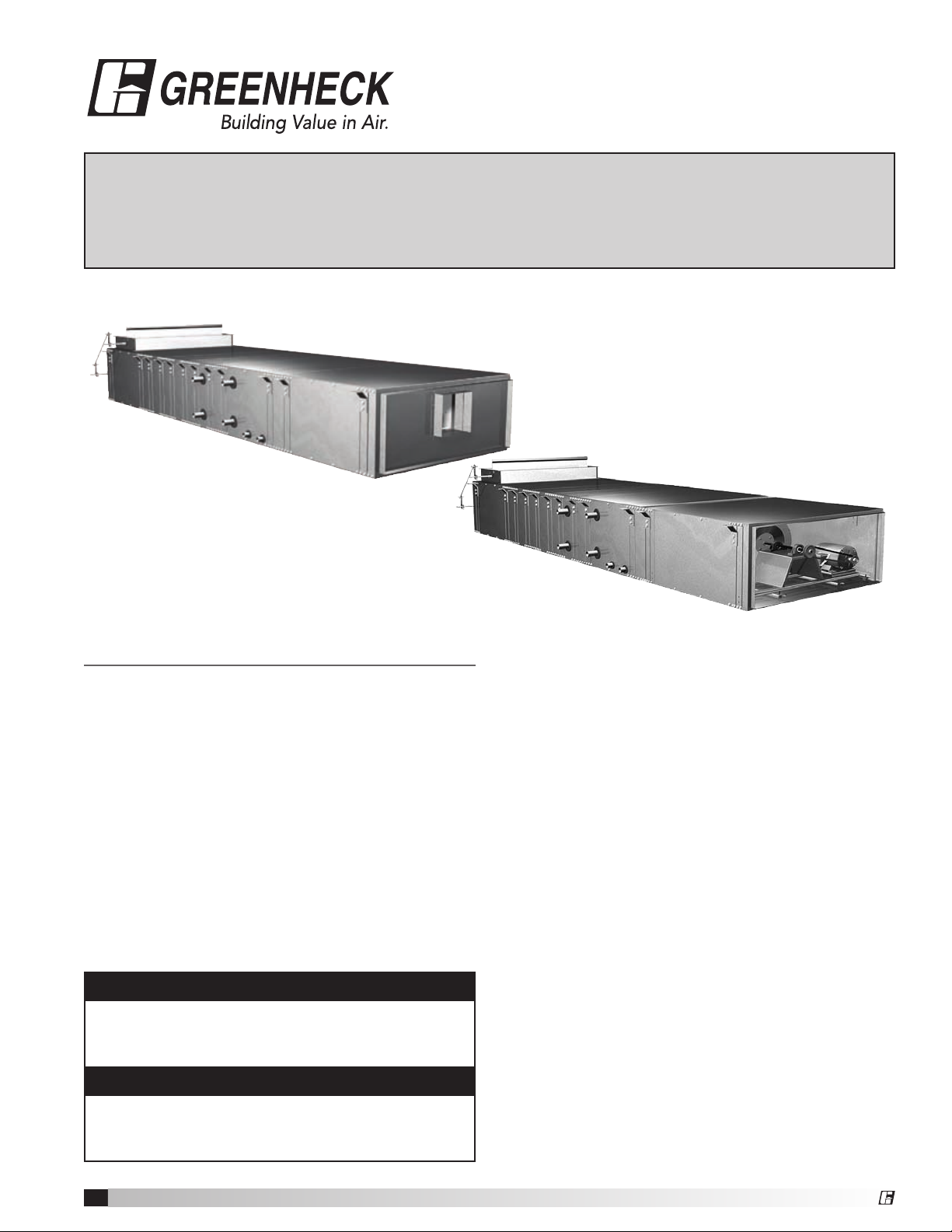
Modular Small Cabinet Fan
Installation, Operation and Maintenance Manual
Please read and save these instructions. Read carefully before attempting to assemble, install, operate or maintain the
product described. Protect yourself and others by observing all safety information. Failure to comply with instructions
could result in personal injury and/or property damage! Retain instructions for future reference.
Model MSCF-BI
Model MSCF-FC
General Safety Information
Only qualified personnel should install this unit.
Personnel should have a clear understanding of these
instructions and should be aware of general safety
precautions. Improper installation can result in electric
shock, possible injury due to coming in contact with
moving parts, as well as other potential hazards.
Other considerations may be required if high winds
or seismic activity are present. If more information
is needed, contact a licensed professional engineer
before moving forward.
1. Follow all local electrical and safety codes, as
well as the National Electrical Code (NEC), the
National Fire Protection Agency (NFPA), where
applicable. Follow the Canadian Electric Code
(CEC) in Canada.
DANGER
Always disconnect power before working on or
near a unit. Lock and tag the disconnect switch or
breaker to prevent accidental power up.
CAUTION
2. The rotation of the wheel is critical. It must be
free to rotate without striking or rubbing any
stationary objects.
3. Motor must be securely and adequately
grounded.
4. Do not spin fan wheel faster than the maximum
cataloged fan rpm. Adjustments to fan speed
significantly affects motor load. If the fan RPM is
changed, the motor current should be checked
to make sure it is not exceeding the motor
nameplate amps.
5. Do not allow the power cable to kink or come
in contact with oil, grease, hot surfaces,
or chemicals. Replace cord immediately if
damaged.
6. Verify that the power source is compatible with
the equipment.
7. Never open blower access doors while the fan is
running.
When servicing the unit, motor may be hot enough
to cause pain or injury. Allow motor to cool before
servicing.
Model MSCF Modular Small Cabinet Fan
1
Page 2

®
Receiving
Upon receiving the product, check to make sure
all items are accounted for by referencing the bill
of lading to ensure all items were received. Inspect
each crate for shipping damage before accepting
delivery. Notify the carrier if any damage is noticed.
The carrier will make notification on the delivery
receipt acknowledging any damage to the product.
All damage should be noted on all the copies of the
bill of lading which is countersigned by the delivering
carrier. A Carrier Inspection Report should be filled
out by the carrier upon arrival and reported to the
Traffic Department. If damaged upon arrival, file claim
with carrier. Any physical damage to the unit after
acceptance is not the responsibility of Greenheck Fan
Corporation.
Unpacking
Verify that all required parts and the correct quantity
of each item have been received. If any items are
missing, report shortages to your local representative
to arrange for obtaining missing parts. Sometimes it
is not possible that all items for the unit be shipped
together due to availability of transportation and truck
space. Confirmation of shipment(s) must be limited to
only items on the bill of lading.
Handling
Units are to be rigged and moved by the lifting
brackets provided or by the skid when a forklift is
used. Location of brackets varies by model and size.
Handle in such a manner as to keep from scratching
or chipping the coating. Damaged finish may reduce
ability of unit to resist corrosion.
Storage
Units are protected against damage during shipment. If
the unit cannot be installed and operated immediately,
precautions need to be taken to prevent deterioration
of the unit during storage. The user assumes
responsibility of the unit and accessories while in
storage. The manufacturer will not be responsible
for damage during storage. These suggestions are
provided solely as a convenience to the user.
INDOOR — The ideal environment for the storage of
units and accessories is indoors, above grade, in a
low humidity atmosphere which is sealed to prevent
the entry of blowing dust, rain, or snow. Temperatures
should be evenly maintained between 30°F (-1°C) and
110°F (43°C) (wide temperature swings may cause
condensation and “sweating” of metal parts). All
accessories must be stored indoors in a clean, dry
atmosphere.
Remove any accumulations of dirt, water, ice, or snow
and wipe dry before moving to indoor storage. To
avoid “sweating” of metal parts allow cold parts to
reach room temperature. To dry parts and packages
use a portable electric heater to get rid of any
moisture build up. Leave coverings loose to permit air
circulation and to allow for periodic inspection.
The unit should be stored at least 3½ in. (89 mm) off
the floor on wooden blocks covered with moisture
proof paper or polyethylene sheathing. Aisles between
parts and along all walls should be provided to permit
air circulation and space for inspection.
Inspection and Maintenance during Storage
While in storage, inspect fans once per month. Keep a
record of inspection and maintenance performed.
If moisture or dirt accumulations are found on parts,
the source should be located and eliminated. At each
inspection, rotate the fan wheel by hand ten to fifteen
revolutions to distribute lubricant on motor. Every
three months, the fan motor should be energized. If
paint deterioration begins, consideration should be
given to touch-up or repainting. Fans with special
coatings may require special techniques for touch-up
or repair.
Machined parts coated with rust preventive should
be restored to good condition promptly if signs of
rust occur. Immediately remove the original rust
preventive coating with petroleum solvent and clean
with lint-free cloths. Polish any remaining rust from
surface with crocus cloth or fine emery paper and oil.
Do not destroy the continuity of the surfaces. Wipe
thoroughly clean with Tectyl® 506 (Ashland Inc.) or
the equivalent. For hard to reach internal surfaces or
for occasional use, consider using Tectyl® 511M Rust
Preventive or WD-40® or the equivalent.
REMOVING FROM STORAGE — As units are removed
from storage to be installed in their final location,
they should be protected and maintained in a similar
fashion, until the equipment goes into operation.
Prior to installing the unit and system components,
inspect the unit assembly to make sure it is in working
order.
1. Check all fasteners, set screws on the fan,
wheel, bearings, drive, motor base, and
accessories for tightness.
2. Rotate the fan wheel(s) by hand and assure no
parts are rubbing.
Service Clearance
Units require service clearance for:
• lterreplacement
• coilanddrainpaninspection,cleaningand
replacement
• motoranddriveinspection,maintenanceand
replacement
Access panels are provided for inspection and
cleaning of unit components. Allow service clearance
of 26 inches for removal of filters. Allow a service
clearance equal to the unit width for removal of coils
and drain pan.
Model MSCF Modular Small Cabinet Fan
2
Page 3
®
Table of Contents
Installation
Unit Layout . . . . . . . . . . . . . . . . . . . . . . . . . . . . . . .3
Mounting / Hanging Instructions . . . . . . . . . . . . . 4
Mounting Dimensions ...................... 5
Dimensions / Weights ...................... 6
Filter Sizes / Quantity . . . . . . . . . . . . . . . . . . . . . . 6
Coil Dimensions . . . . . . . . . . . . . . . . . . . . . . . . .7-9
Start-Up
System Start-Up . . . . . . . . . . . . . . . . . . . . . . . . . 10
Troubleshooting
Blower . . . . . . . . . . . . . . . . . . . . . . . . . . . . . . . . . 10
Motor Overamps ......................... 10
Insufficient / Too Much Airflow .............. 10
Excessive Noise or Vibration . . . . . . . . . . . . . . . 10
Start-Up
Coil Module ...........................12-13
Drain Pan / Drain Trap . . . . . . . . . . . . . . . . . . . . 13
Installation
Electric Heater ........................... 14
Operation
Electric Heater ........................... 15
Maintenance
Fan .................................... 16
Coil .................................... 16
Drain Pan ............................... 16
Reference
Start-Up Documentation ................... 17
Maintenance Log . . . . . . . . . . . . . . . . . . . . . .18-19
Warranty . . . . . . . . . . . . . . . . . . . . . . . . .Backcover
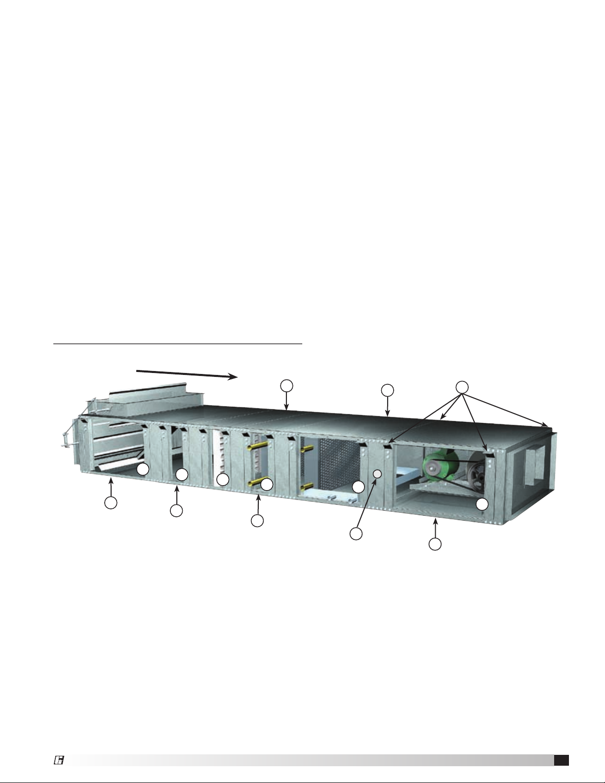
Unit Layout
Airflow
8
6
1. Fan and Cabinet Section
2. Cooling Section
• ChilledWater
• DXCoils
3. Heating Section
• HotWater
• SteamCoils
4. Filter Section
Filter may be mounted in Mixing Box Section
5. Plenum Section
8
5
8
4
8
3
9
6. Mixing Box Section
7. Lifting Lugs
Four (4) lifting lugs for each section
8. Side Access Panels
Right and left access to each section
(image shows panels removed)
9. 7/8-inch knockout is provided for the
recommended electrical wiring penetration or
disconnect switch.
2
8
7
8
1
Model MSCF Modular Small Cabinet Fan
3
Page 4
®
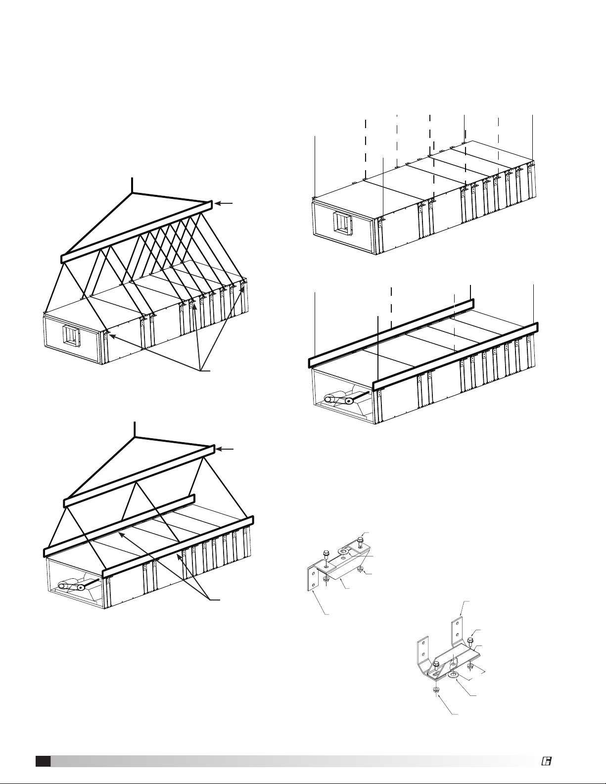
Hanging Bracket
Part No. 710774
Drawing No. 85537
Bridge Bracket
Part No. 711779
Drawing No. 89814
One required per assembly
3/4 inch Flat Washer
One per assembly as needed
3/8-16x3/4 Spinlock Bolt
Two required per assembly
3/8-16 Spinlock Nut
Two required per assembly
HANGING ASSEMBLY
Hanging Bracket
Part No. 710774
Drawing No. 85537
Hanging Bracket
Part No. 710774
Drawing No. 85537
Bridge Bracket
Part No. 711779
Drawing No. 89814
One required per assembly
Bridge Bracket
Part No. 711779
Drawing No. 89814
One required per assembly
3/4 inch Flat Washer
One required per assembly
3/4 inch Flat Washer
One per assembly as needed
3/8-16x3/4 Spinlock Bolt
Two required per assembly
3/8-16x3/4 Spinlock Bolt
Two required per assembly
3.0 inch
3/8-16 Spinlock Nut
Two required per assembly
3/8-16 Spinlock Nut
Two required per assembly
HANGING ASSEMBLY
BASE ASSEMBLY
Mounting Instructions
Greenheck’s Modular Small Cabinet Fan (MSCF)
should be lifted by the factory supplied lifting lugs
(see Figure 1) or frame rails and a spreader bar
(see Figure 2) to prevent damage from occurring to
the equipment. Avoid twisting or uneven lifting of
equipment. Do not lift equipment by coil connections
or headers. The unit must remain upright during lifting.
All access doors and panels must be closed during
lifting to avoid damage.
Spreader Bar
Hanging Instructions
The MSCF should be hung by the factory supplied
lifting lugs or field supplied frame rails as shown
respectively in Figures 3 and 4. The number of
hanging brackets used will be determined by the
number of fan modules.
Figure 3
4
Figure 1
Figure 2
Model MSCF Modular Small Cabinet Fan
Lifting lugs
Figure 4
Spreader Bar
External Mounting Isolation
The MSCF is available with external neoprene or
spring isolation options. When external isolation is
selected, a bridge bracket will be provided to reduce
installation time (see Figure 5).
Frame Rails
(by others)
Figure 5
Page 5
®
24
PLENUM
12
PLENUM
CHILLED
WATER
COIL
HEATING
COIL
VERTICAL
FILTER
FAN
MIXING BOX
w/DAMPER
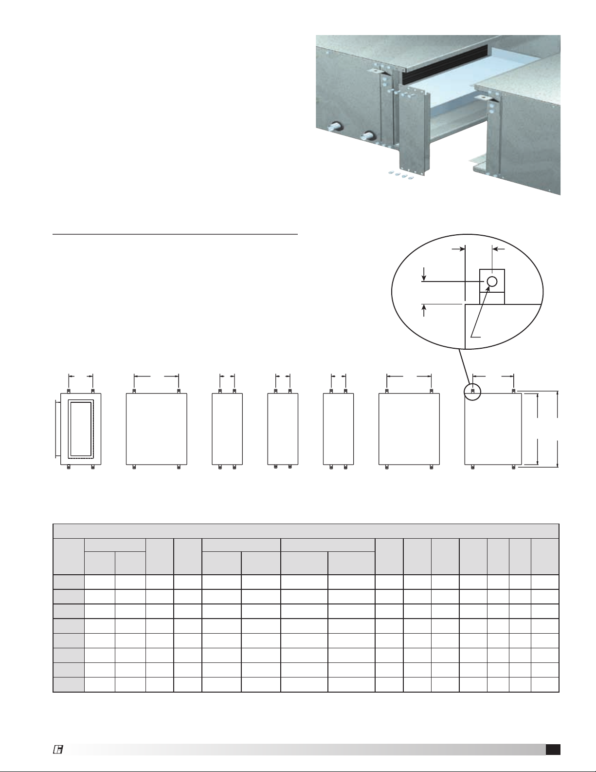
Modular Construction
The MSCF is designed to be modular so it can be
mounted as an assembly or as individual sections
when the appropriate lifting equipment is not
available.
MSCF Mounting Dimensions
K
J
L
A
B C D E
F
G
Mixing 24 in. 12 in. Filter *Heating Cooling / Combo Fan
Box Plenum Plenum Coil
Horizontal Hanging
Unit
Size
w/o
Filter
A
w/
Filter
B C
Vertical Sloped
D E
Hot Water
1 & 2 Row
15 6.75 18.5 18.5 6.75 6.75 18.5 6.75 9.5 18.5 19 38 2.5 3 .5 43
20 6.75 18.5 18.5 6.75 6.75 18.5 6.75 9.5 18.5 19 38 2.5 3 .5 43
25 6.75 21 18.5 6.75 6.75 21 6.75 9.5 18.5 23 38 2.5 3 .5 43
30 6.75 25 18.5 6.75 6.75 25 6.75 9.5 18.5 26 38 2.5 3 .5 43
45 6.75 26 18.5 6.75 6.75 26 6.75 9.5 18.5 26 50 2.5 3 .5 55
50 6.75 26 18.5 6.75 6.75 26 6.75 9.5 18.5 32 50 2.5 3 .5 55
65 6.75 32 18.5 6.75 6.75 28 6.75 9.5 18.5 36 50 2.5 3 .5 55
85 6.75 32 18.5 6.75 6.75 28 6.75 9.5 18.5 36 62 2.5 3 .5 67
*See CAPS for electric heating dimensions.
All dimensions are in inches.
4 Row HW
& Steam
F G H J K L M
H
M
Model MSCF Modular Small Cabinet Fan
5
Page 6
®
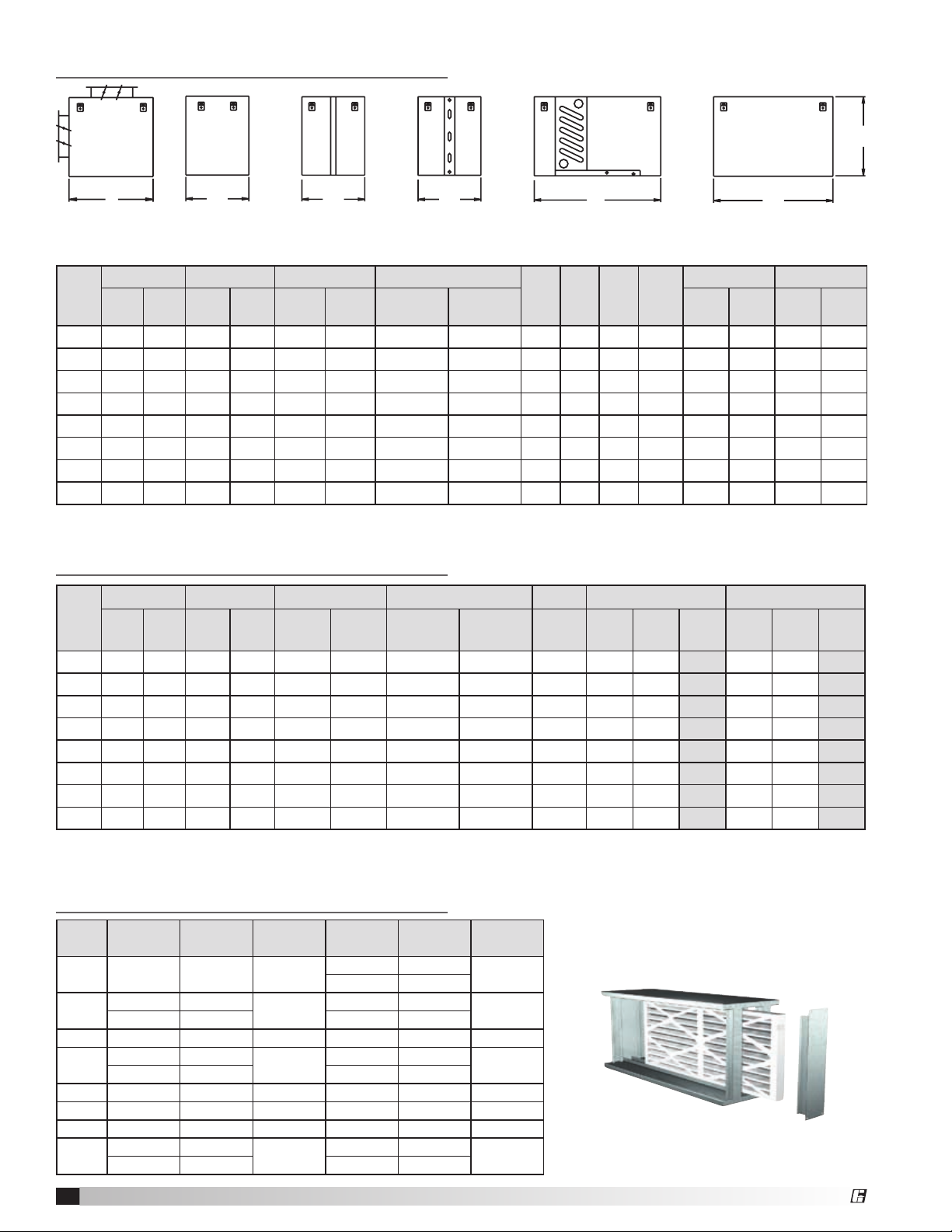
Dimensional Data
24
PLENUM
12
PLENUM
CHILLED
WATER
COIL
HEATING
COIL
VERTICAL
FILTER
FAN
MIXING BOX
w/DAMPER
12
PLENUM
CHILLED
WATER
COIL
HEATING
COIL
VERTICAL
FILTER
FAN
G
A
B C D E
Mixing Plenum Filter *Heating Cooling / Combo Fan
Box Coil
Unit
Size
15 11 24.5 12.75 24.5 12.75 24.5 12.75 15.5 24.5 25 11 38 9 36 4 6.75
20 14 24.5 12.75 24.5 12.75 24.5 12.75 15.5 24.5 25 14 38 12 36 6.5 6.75
25 16 27 12.75 24.5 12.75 27 12.75 15.5 24.5 29 16 38 14 36 8 8.5
30 18.5 31 12.75 24.5 12.75 31 12.75 15.5 24.5 32 18.5 38 16.5 36 9 9
45 18.5 32 12.75 24.5 12.75 32 12.75 15.5 24.5 32 18.5 50 16.5 48 9 10
50 21 32 12.75 24.5 12.75 32 12.75 15.5 24.5 38 21 50 19 48 10.25 10
65 26 38 12.75 24.5 12.75 38 12.75 15.5 24.5 42 26 50 24 48 12 12.75
85 26 38 12.75 24.5 12.75 38 12.75 15.5 24.5 42 26 62 24 60 12 15
*See CAPS for electric heating dimensions.
All dimensions are in inches.
A B C D
w/o
w/
Filter
12 in. 24 in. Vertical Sloped
Filter
Hot Water
1 & 2 Row
4 Row HW
& Steam
E F G
Unit
Width
Height Width Height Width
Weights
Unit
Size
15 80 107 31 57 34 61 61 86 145 94 50 144 - - -
20 95 126 36 68 41 72 72 101 171 111 50 161 - - -
25 105 140 40 75 45 80 80 112 190 130 60 190 168 60 228
30 118 157 45 84 50 90 88 123 209 150 75 225 182 75 257
45 132 176 50 94 55 100 99 138 234 194 75 269 239 100 339
50 151 202 58 108 64 115 113 159 269 253 100 353 279 100 379
65 197 263 75 141 77 150 136 190 323 328 125 453 333 100 433
85 226 302 85 170 90 175 140 196 350 360 140 500 375 100 475
All weights are approximated. Motor weights may very depending on enclosure type and horsepower.
**Weightinformationforhotwater,steam,chilledwaterandDXcoilsiswetweight.
*See CAPS for electric heat dimensions.
A B C **D **E F (FC) F (BI)
w/o
Filter
Filter
w/
12 in. 24 in. Vertical Sloped
Hot Water
1 & 2 Row
4 Row HW
& Steam
CW/DX Fan
Max
Motor
Total Fan
F
Inlet Outlet
Max
Motor
Total
Filter Sizes and Quantity
Unit
Size
6
Vertical Quantity
15 9x18 2 1.8
20
25 14x18 2 3.0 16x20 2 3.8
30
45 16x24 2 4.8 24x24 2 7.2
50 18x24 2 5.4 24x24 2 7.2
65 24x24 2 7.2 24x24 4 14.4
85
12x12 1
12x24 1 16x20 1
16x16 1
16x20 1 24x24 1
12x24 1
24x24 2 24x24 4
Model MSCF Modular Small Cabinet Fan
Face
Area
2.5
3.4
8.9
Sloped Quantity
12x12 1
12x24 1
16x16 1
12x24 1
12x24 2
Face
Area
2.5
3.4
5.3
17.8
Page 7

®
Coil Dimensions
Inlet
Outlet
Outlet
Inlet
Outlet
Inlet
Hot Water • 1 and 2 Row
A
Hot Water • 4 Row
A
Unit
Size
Face
Area
A B C D E F
15 1.6 38 12.75 11.0 3.0 0.75 .5
20 2.2 38 12.75 14.0 4.5 0.75 .5
3
E
C
F
D
25 2.7 38 12.75 16.0 4.0 0.88 .5
30 3.2 38 12.75 18.5 4.0 0.88 .5
45 4.5 50 12.75 18.5 4.0 0.88 .5
50
5.2 50 12.75 21.0 4.0 1.13 .5
65 6.7 50 12.75 26.0 4.0 1.38 .5
85 8.6 62 12.75 26.0 4.0 1.38 .5
All dimensions are in inches.
NOTE
6
B
G
F
D
E
C
B
Fluid enters the coil from the bottom connection
(Inlet) and exits from the top (Outlet).
Unit
Size
All dimensions are in inches.
Face
Area
A B C D E F G
15 1.6 38 15.50 9.38 3.188 0.750 4.0 11.0
20 2.2 38 15.50 9.38 3.188 0.750 4.5 14.0
25 2.7 38 15.50 9.38 3.188 0.875 4.0 16.0
30 3.2 38 15.50 9.38 3.188 0.875 4.0 18.8
45 4.5 50 15.50 9.38 3.188 1.375 4.0 21.0
50 5.2 50 15.50 9.38 3.188 1.375 4.0 26.0
65 6.7 50 15.50 9.38 3.188 1.375 4.0 26.0
85 8.6 62 12.75 9.38 3.188 1.375 4.0 26.0
NOTE
With airflow from left to right, the fluid enters the coil
from the bottom connection (Inlet) and exits from the
top (Outlet). The other two coil connections should
be capped off (Cap).
Steam • 1 and 2 Row
Unit
Size
Face
Area
A B C D E F G
15 1.6 38 15.50 7.75 3.31 1.5 5.18 11.0
20 2.2 38 15.50 7.75 3.00 1.5 6.50 14.0
25 2.7 38 15.50 7.75 3.31 2.5 7.69 16.0
30 3.2 38 15.50 7.75 3.00 2.5 9.00 18.5
45 4.5 50 15.50 7.75 3.00 2.5 9.00 18.5
G
50 5.2 50 15.50 7.75 4.31 2.5 10.18 21.0
65 6.7 50 15.50 7.75 3.00 2.5 12.50 26.0
F
A
C
Electric Heat • See our Computer Aided Product Selection (CAPS) Software Program for dimensional data.
B
D
E
85 8.6 62 15.50 7.75 3.00 2.5 12.50 26.0
All dimensions are in inches.
NOTE
Steam enters the coil from the center connection
(Inlet) and exits from the bottom (Outlet).
Model MSCF Modular Small Cabinet Fan
7
Page 8

®
Coil Dimensions - continued
Chilled Water • 4, 6 or 8 Row
3
With airflow from left to right, the fluid enters the coil
1
C
from the bottom connection (Inlet) and exits from the
top (Outlet). The other two coil connections should
be capped off (cap).
A
B
Unit
Size
Face
Area
A B C
4 Row 6 Row 8 Row 4 & 6 Row 6 Row
15 1.6 38 24.5 11.0 10 12 14 0.75 1.38
20 2.2 38 24.5 14.0 10 12 14 0.75 1.38
25 2.7 38 24.5 16.0 10 12 14 0.88 1.38
30 3.2 38 24.5 18.5 10 12 14 0.88 1.38
45 4.5 50 24.5 18.5 10 12 14 0.88 1.38
50 5.2 50 24.5 21.0 10 12 14 1.38 1.63
65 6.7 50 24.5 26.0 10 12 14 1.38 1.63
85 8.6 62 24.5 26.0 10 12 14 1.38 1.63
All dimensions are in inches.
J K
Airflow
K
6.5
Outlet
(cap)
J
13.25
NOTE
(cap)
Inlet
18.5
.75
1.5
3.75
3.88
2
Direct Expansion (DX) • 4, 6 or 8 Row
(Orifice Code 18/19)
Coil connection made inside housing.
Two inch hole is provided.
3
With airflow from left to right, the fluid enters the coil
C
1
Unit
Size
A
Face
Area
A B C
B
L M N P
4 Row 6 Row 8 Row All All
15 1.6 38 24.5 11.0 8.75 10.75 12.75 5.25 0.63 0.63 1.38
20 2.2 38 24.5 14.0 8.75 10.75 12.75 7.00 0.63 0.63 1.38
25 2.7 38 24.5 16.0 8.75 10.75 12.75 8.00 0.88 1.38 1.38
30 3.2 38 24.5 18.5 8.75 10.75 12.75 9.00 0.88 1.38 1.38
45 4.5 50 24.5 18.5 8.75 10.75 12.75 9.00 0.88 1.38 1.38
50 5.2 50 24.5 21.0 8.75 10.75 12.75 10.25 0.88 1.38 1.63
65 6.7 50 24.5 26.0 8.75 10.75 12.75 13.00 1.13 1.38 1.63
85 8.6 62 24.5 26.0 8.75 10.75 12.75 13.00 1.13 1.38 1.63
All dimensions are in inches.
from the center connection (Inlet) and exits from the
bottom (Outlet). The other coil connections should
be capped off (cap).
4 & 6
Row
8 Row
NOTE
Airflow
(cap)
Outlet
N
6.5
Inlet
L
13.25
18.5
3.88
P
M
2
3.75
1.5
Model MSCF Modular Small Cabinet Fan
8
Page 9

®
Coil Dimensions - continued
Direct Expansion (DXI) • 4, 6 or 8 Row
Dual Circuit with 50/50 Face Interlaced Construction
Coil connection made inside housing.
Two inch hole is provided.
3
C
1
NOTE
The first suction header on the entering air side
of the coil is circuited to the top distributor. With
airflow from left to right, the fluid enters the coil
from the center connection (Inlet) and exits from the
bottom (Outlet). The other connections should be
capped off (cap).
A
B
Unit
Size
Face
Area
A B C
D E
4 Row
6 & 8
Row
4 Row 6 Row 8 Row
F G
30 3.2 38 24.5 18.5 9.25 11.0 7.88 8.50 8.5 7.00 12.0
45 4.5 50 24.5 18.5 9.25 11.0 7.88 8.50 8.5 7.00 12.5
50 5.2 50 24.5 21.0 9.25 11.0 7.50 8.50 8.75 7.75 13.5
65 6.7 50 24.5 26.0 9.25 11.0 8.12 8.75 8.75 9.50 17.0
85 8.6 62 24.5 26.0 9.25 11.0 8.12 8.75 8.75 9.50 17.0
All dimensions are in inches.
Airflow
Outlet 1
6.5
(cap) (cap)
Outlet 2
3.75
E
D
13.25
18.5
Inlet 1
Inlet 2
F
G
1.5
2
Model MSCF Modular Small Cabinet Fan
9
Page 10

®
Backward
Inclined
Airfoil
Forward
Curved
R
o
t
a
t
i
o
n
R
o
t
a
t
i
o
n
R
o
t
a
t
i
o
n
Forward
Curved
R
o
t
a
t
i
o
n
C
l
o
c
k
w
i
s
e
G
System Start-Up
For proper unit function and safety, follow everything
in this start-up procedure in the order presented.
This is to be done after the electrical connections are
complete.
PRE-START CHECK LIST
1. Disconnect and lock-out all power switches to fan.
2. Check all fasteners, set screws and locking
collars on the fan, bearings, drive, motor base and
accessories for tightness.
3. Rotate the fan wheel by hand and assure no parts
are rubbing.
4. Check the V-belt drive for proper alignment and
tension.
Unit Size G
25 - 50 1/4 inch
65 - 85 3/8 inch
Wheel Overlap Dimensions
SPECIAL TOOLS REQUIRED
•VoltageMeter
•Tachometer
•AmperageMeter
1. Check Voltage
Before starting the unit, compare the supplied voltage
with the unit’s nameplate voltage and the motor
voltage. Units are not provided with thermal overload
protection unless a control center has been ordered
with the unit or the motor has been selected with
thermal overload protection.
2. Check Blower Rotation
A common problem is wheel rotation in the wrong
direction. For centrifugal fans, incorrect wheel rotation
will provide poor air performance, motor overloading
and possible burnout. Rotation should be checked
while the fan is coasting to a stop. Proper wheel
rotation is shown.
any two supply power connections will reverse the
direction of rotation.
To reverse the rotation, turn the power off and use the
following procedure:
• Forsinglephaseunits,rewirethemotorperthe
instructions on the motor.
• Forthreephaseunits,interchangeanytwo
power leads. This can be done at the motor
starter.
3. Check for Vibration
Check for unusual noise, vibration or overheating of
bearings. Excessive vibration may be experienced
during initial start-up. Left unchecked, excessive
vibration can cause a multitude of problems, including
structural and/or component failure. Many conditions
can be discovered by careful observation. If the
problem is wheel unbalance, in-place balancing can
be done providing there is access to the fan wheel.
Generally, fan vibration and noise is transmitted
to other parts of the building by the ductwork. To
eliminate this undesirable effect, Greenheck has
used a heavy canvas connection between the scroll
and the discharge of the fan. If noise is an issue, we
recommend using heavy canvas connections on the
inlet of the fan. Refer to the Troubleshooting section of
this manual if a problem develops.
4. Air Volume Check and Measurement
Along with the building balance, the unit’s air volume
(cfm) should be measured and compared with its
rated air volume. This unit is flexible for varying air
volume, but the actual air volume should be known for
making final adjustments. The most accurate way to
measure the air volume is by using the pitot traverse
method in the ductwork away from the blower. Other
methods can be used, but should be proven and
accurate. To adjust the air volume, change the fan rpm
or the system losses. See Troubleshooting section in
this guide.
5. Measure Motor Voltage, Amperage
and Fan RPM
All access doors must be installed. Measure and
record the input voltage and motor amperage(s).
To measure the fan RPM, the blower door will need to
be removed. Minimize measurement time because the
motor may over amp with the door removed.
Compare measured amps to the motor nameplate
full load amps and correct if over amping. See the
Troubleshooting section in this guide.
Proper Wheel Rotation
When connecting a 3-phase motor, there is a 50%
chance that the fan will run backwards. Changing
Model MSCF Modular Small Cabinet Fan
10
Page 11

®
Troubleshooting
NOTE
Before taking any corrective action, ensure unit is incapable of operation during repairs.
Symptom Possible Cause Corrective Action
Blown fuse or open circuit breaker Replace fuse or reset circuit breaker and check amps
Blower fails to
operate
Motor overamps
Insufficient airflow
Broken fan belt Replace
Defective motor or capacitor Replace
Motor starter overloaded Reset starter and check amps
Airflow too high Check airflow and adjust drives if needed
Static pressures are higher or lower
than design
If higher, ductwork should be improved
If lower, fan RPMs should be lower
Blower rotation is incorrect Check rotation and correct
Motor voltage incorrect Check motor nameplate and supplied voltage
Motor horsepower too low
See specifications and catalog for fan curves to determine
if horsepower is sufficient
Shorted windings in motor Replace motor
Mixing box damper not fully open Adjust damper linkage or replace damper motor
System static pressure too high
Improve ductwork to eliminate losses using good duct
practices
Blower speed too low Check for correct drives and RPMs with catalog data
Mixing box dampers closed Open and adjust
Dirty or clogged filters Clean or replace
Leaks in ductwork Repair
Elbows, or other obstructions may
restrict fan outlet
Correct or improve ductwork
Too much airflow
Excessive noise or
vibration
Belt slippage Adjust belt tension
Unit running backwards
Correct as shown in System Start-Up section, Step #2,
page 10
Excessive dirt buildup on wheels Clean wheel
Blower fan speed too high Check for correct fan RPM
Filter(s) not in place Install filters
Insufficient static pressure
(airflow resistance)
Wheel improperly aligned and rubbing on
housing
Induce static pressure into system ductwork
Center wheel
Loose wheel on shaft Tighten wheel setscrew
Loose motor or blower sheave Tighten sheave setscrew
Belts too loose Adjust belt tension after 24 hours of operation
Belts too tight
Loosen to maintain 3/8 inch deflection per ft. of span
between sheaves
Worn belt Replace
Motor base or blower loose Tighten mountings bolts
Worn bearings Replace
Bearing and drive alignment Realign
Motor out of balance Replace
Unbalanced wheel caused by excessive
dirt and grease buildup
Replace or rebalance
Sheaves eccentric or out-of-balance Replace or rebalance
Accumulation of material on wheel Clean wheel and housing
Foreign objects in wheel or housing Remove objects. Check for damage or unbalance.
Model MSCF Modular Small Cabinet Fan
11
Page 12

®
Start-Up of Coil Module
Steam Main
Return Main
Strainer
Gate Valve
Control Valve
Modulating Two-Position
Check Valve
Vacuum Breaker
Float & Thermostat Trap
Hot Water and Chilled Water
1. Piping should be in accordance with accepted
industry standards. Pipework should be supported
independently of the coils. Water pipes are copper
with sweat connections. USE WET TOWEL TO
AVOID BURNING COIL CONNECTION GROMMETS.
When installing coupling, do not apply undue
stress to the connection extending through the
unit. Use a back-up pipe wrench to avoid breaking
the weld between coil connection and header.
2. Connect the water supply to the bottom
connection on the air-leaving side and the water
return to the top connection on the air-entering
side. The extra bottom connection can be used for
an auxiliary manual drain connection, and the extra
top connection may be used for an automatic air
vent, or the extra connections can be capped. To
ensure proper venting, an external air vent in the
piping is recommended. Connecting the supply
and/or return in any other manner will result in very
poor performance. CAP UNUSED CONNECTIONS.
3. The air vent at the uppermost point should be
temporarily opened during system start-up to
release all of the air from the coil. To maintain heat
transfer capacity, periodically vent any air in coil.
Vent to be located behind connections side access
door.
4. Water coils are not normally recommended for
use with entering air temperatures below 40°F.
No control system can be depended on to be
100% safe against freeze-up with water coils.
Glycol solutions or brines are the only safe media
for operation of water coils with low entering air
conditions.
WARNING
Continuous water circulation through the coil at all
times is highly recommended.
5. Pipe sizes for the system must be selected on the
basis of the head (pressure) available from the
circulation pump. Piping should be in accordance
with accepted industry standards.
6. For chilled water coils, the condensate drain
pipe should be sized adequately to ensure the
condensate drains properly. See Drain Pan Traps
section and related drawing.
Direct Expansion (DX) Coils
1. Piping should be in accordance with accepted
industry standards. Pipework should be supported
independently of the coils. Undue stress should not
be applied at the connection to coil headers.
2. The condensate drain pipe should be sized
adequately to ensure the condensate drains
properly. See Drain Pan Traps and related drawing.
Model MSCF Modular Small Cabinet Fan
12
3. When connecting suction and liquid connections,
make sure the coil is free from all foreign material.
Make sure all joints are tight and free of leakage.
4. Greenheck does not supply compressor or
condensingunits,forfurtherinstructiononDXcoil
installation and operation contact your compressor
and/or condenser manufacturer.
DXI coils have dual connections and should be used
with two compressors.
WARNING
Standard unit insulation of 1.5 lbs. density has an
insulation R-value of 3.7.
For applications where the unit discharge
temperatures are below 55°F and the unit is installed
in a warm, humid environment, additional insulation
may need to be applied to the exterior of the unit to
prevent condensation.
Steam Coils
Application Recommendations
Satisfactory operation and
service life are best
ensured when coils
are installed with
proper piping,
trap and support
arrangement.
The following
notes and
drawing are
recommended
for the coil unit
installation and
operation.
General
1. Provide
separate
supports and
hangers for the
unit and the piping.
2. Be certain that adequate piping flexibility is
provided. Stresses resulting from expansion of
closely coupled piping and coil arrangement can
cause serious damage.
3. Standard steam coils are pitched in the casings
when installed for horizontal airflow. The casing
must be level after the unit is installed for proper
condensate drainage. If condensate is not
removed, the coil will suffer from water hammering
and will have a shortened life. On vertical airflow
applications, the coils must be pitched when
installed.
4. Do not reduce pipe size at the coil return
connection. Carry return connection size through
the dirt pocket, making the reduction at the branch
leading to the trap.
Steam Coil Piping
Page 13

®
2P = minimum
2P = minimum
General - continued
5. It is recommended that vacuum breakers be
installed on all applications to prevent retaining
condensate in the coil. Generally, the vacuum
breaker is to be connected between the coil inlet
and the return main. The vacuum breaker should
be open to the atmosphere and the trap design
should allow venting of large quantities of air.
6. Do not attempt to lift condensate when using
modulating or on-off control.
7. Do not reduce the pipe size leaving the coil.
Traps
1. Size traps in accordance with the manufacturer’s
recommendations. Be certain that the required
pressure differential will always be available. DO
NOT UNDERSIZE.
2. Float and thermostatic or bucket traps are
recommended for low pressure steam. On high
pressure systems, bucket traps are normally
recommended. The thermostatic traps should be
used only for air venting.
3. Bucket traps are recommended for use with on-off
control only.
4. Locate traps at least 12 inches below the coil
return connection.
Controls
1. On high pressure installations, a two-position
steam valve with a face and bypass arrangement is
preferred where modulating control is required.
2. Modulating valves must be sized properly. DO NOT
UNDERSIZE.
Freezing Conditions (entering air below 35°F)
1. 5 PSI steam must be supplied to the coil at all times.
2. Modulating valves are not recommended. Control
should be by means of face and bypass dampers.
3. Provision should always be made to thoroughly
mix fresh air and return air before it enters the
coil on return air units. Also, temperature control
elements must be properly located to obtain true
air mixture temperatures.
4. As additional protection against freeze-up, the trap
should be installed sufficiently —far below the coil
to provide an adequate hydrostatic head to ensure
removal of condensate during an interruption in the
steam pressure. Estimate 3 feet for each 1 PSI of
trap differential required.
5. On start-up, admit steam to coil ten minutes before
admitting outdoor air.
6. Provision must be made to close fresh air dampers
if steam supply pressure falls below minimum
specified.
Drain Pan / Drain Trap
Drain lines and traps should be run full size from the
drain pan connection. Drain pans should have drain
lines and traps to permit the condensate from the
coils to drain freely. On all units with drain pans, the
trap depth and the distance between the trap outlet
and the drain pan outlet should be twice the static
pressure (P) in the drain pan section under normal
operation to assure the trap remains sealed.
Drain Pan / Drain Trap
Model MSCF Modular Small Cabinet Fan
13
Page 14

®
Installation of Electric Heater
(optional)
WARNING
Electrical Shock Hazard! Disconnect all power
sources before doing any work on the unit.
General:
The requirements and practices described below
are based on the National Electric Code (NEC) and
The Space Heating Standard of the Underwriters
Laboratories Inc. (UL). Although UL requirements
are uniform throughout the country, local electrical
codes may deviate from the National Electrical Code.
Therefore, local inspection authorities should be
consulted regarding local requirements.
Electrical Wiring Instructions:
1. Use the wiring diagram supplied with the heater
as a guide in correlating field wiring with the
heater internal wiring.
2. All field wiring to the heater must meet the
requirements of the National Electric Code and
any other applicable local or state codes.
3. Wiring to the heater must be rated for 75°C
(167°F) minimum.
4. If heater does not have a built-in disconnect
switch or main circuit breaker, install a remote
disconnect (furnished by others) in accordance
with the National Electric Code, Article 424-65.
Calculation of Line Currents (amps):
Single Phase Current =
EXAMPLE: 5 kW, 208 volt
5000 watts
208 volts
= 24 amps
Three Phase Current =
EXAMPLE: 14.4 kW, 208 volt
14400 watts
208 volts x 1.73 360
=
14400
watts
volts
watts
volts x 1.73
= 40 amps
Sizing of Supply Conductors
The required minimum size of supply conductors
is marked at the field wiring terminals within the
heater control box or reference the Supply Wire Size
table included in this section. The wire gauges are
calculated for 125% of the heater line current as
required by the National Electric Code, Article 424-3(b)
based on conductor insulation rated for 75°C (167°F).
Supply Wire Size
(Not more than six conductors in Single Conduit 1)
AWG or
MCM
14 12 0000 184
12 16 250 204
10 24 300 228
8 36 350 248
6 52 400 268
4 68 500 304
3 80 600 336
2 92 700 368
1 104 750 380
0 120 800 392
00 140 900 416
000 160 1000 436
1
For 7-24 conductors in raceway or cable, reduce allowable
heater line currents to 87½% of those shown above.
2
Based on 30°C. (86°F) ambient temperature, for higher
ambient temperature see National Electric Code table
310-16 and 310-18 Note 13.
3
Based on 80% of ratings in the National Electric Code
table 310-16 for 75°C insulation.
Max. Heater
Line Current
Copper
3
2
AWG or
MCM
Max. Heater
Line Current
Copper
3
2
Effect of Low Voltage on Wattage and
British Thermal Unit (BTU)
The heating elements may be used on voltages
lower than the design voltage of the heater, however,
the wattage and BTU output will be reduced to the
percentages listed in the table below.
De-rated Wattage for Low Voltage
% of
Heater
Voltage
Line
Voltage
Heater
Wattage
Heater
Voltage
Line
Voltage
and BTU
480
277
240
Model MSCF Modular Small Cabinet Fan
14
460 92
440 84 190 83
265 92
254 84 110 84
230 92
220 84
208 75
200 69
208
120
200 92
115 92
% of
Heater
Wattage
and BTU
Page 15

®
Sequence of Operation - Electric
Heater
1. Electric heaters are divided in to equally sized
steps. For example, a 60 kW heater with 3 steps
will have 20 kW per step. The thermostat and
step controller will control these steps.
2. 120 Volt power from the control center (when
supplied) or by others with out a control center,
is delivered to the electric heater for the step
controller. This power must be interlocked with
the supply fan, so when the fan is off, the heater
control power is off.
3. A step control with the thermostat set to
70ºF the heater will be off with a temperature
sensing above 70ºF. As the temperature varies
the steps turn on and off to hold the setpoint
discharge temperature. The colder the discharge
temperature becomes the more steps the
controller will energize.
4. With a step controller, in addition to the fan
interlock mentioned in Step 2, the heater has an
airflow switch to prove that airflow is established
before energizing the steps. The heater also
has an automatic resetting highlimit switch and
manual resetting highlimit switch set above the
automatic switch to protect from overheating.
5. For more detailed information on your specific
controller, please review the controller spec
sheet supplied with the heater.
Model MSCF Modular Small Cabinet Fan
15
Page 16

®
Fan Maintenance
Belt Span
Deflection =
Belt Span
64
C
l
o
c
k
w
i
s
e
C
l
o
c
k
w
i
s
e
G
CORRECT WRONG WRONG WRONG
Greenheck recommends these procedures to ensure
trouble-free operation of this unit. It is especially
important to maintain heater units for clean and
efficient operation. Most unit failures can be attributed
to poor setup or poor maintenance.
A record of maintenance performed on this unit
should be kept. This information will provide essential
information if problems are encountered. A section at
the back of this manual is provided for recording the
unit’s maintenance history.
CAUTION
When performing any maintenance on this unit,
be certain the power is disconnected and cannot
be accidentally turned on. The control center
disconnect can be locked in the off position.
Two Weeks after Start-Up
Belts - Belts tend to stretch after a period of
time. They should be
periodically checked
for wear and tightness.
Approximately 3/8 inch
of deflection per ft.
of span between
sheaves is standard for
belt tightness. When
replacing belts, use the
same type as supplied
with the unit. Matched
belts should always be
used on units with multi-groove pulleys.
If adjustments are made, it is very important to check
the pulleys for proper alignment. Misaligned pulleys
lead to excessive belt wear, vibration, noise and
power loss.
Belt Alignment
Replacement of belts can be accomplished by
loosening the motor to the point where the belts
can be removed by hand. Do not force belts on or
off as this may cause breakage of cords leading to
premature belt failure. Belts should be adjusted as
above.
NOTE: For motors of 1 hp or less a
smaller sliding base bracket
is used to attach to blower.
Every Three (3) Months
Filters - The filter in the unit should be inspected
at least every three (3) months. Depending on the
environment, filters could require changing or cleaning
more or less often. The filters can be slid out of the
coil connection side of the unit.
If washable filters are installed, they can be washed in
warm soapy water. An adhesive spray can be applied
to increase filter efficiency.
If disposable filters are installed, check by holding up
to a light source. If light cannot pass through the filter,
it should be replaced. Replacement filters should be
of the same manufacturer and size. When reinstalling
filters, be sure to install with the airflow in the correct
direction indicated on the filter.
Yearly
Bearings — Most bearings are permanently
lubricated and require no further lubrication under
normal use. Normal use being considered -20ºF to
120ºF and in a relatively clean environment. Some
bearings are re-lubricatable and will need to be regreased depending on fan use. Check your bearings
for grease fittings to find out what type of bearing
you have. If your fan is not being operated under
normal use, bearings should be checked monthly for
lubrication.
Motors — Motor maintenance is generally limited to
cleaning and lubrication (where applicable). Cleaning
should be limited to the exterior surfaces only.
Removing dust and grease buildup on motor housing
assures proper motor cooling. Greasing of motors
is intended only when grease fittings are provided.
Many fractional motors are permanently lubricated
and require no further lubrication. Motors supplied
with grease fittings should be greased in accordance
with manufacturer’s recommendations. When motor
temperature does not exceed 104ºF (40ºC), the grease
should be replaced after 2000 hours of running time
as a general rule.
Wheels — Wheels require very little attention when
moving clean air. Occasionally, oil and dust may
accumulate on the wheel causing imbalance. When
this occurs the wheel and housing should be cleaned
to assure smooth and safe operation. Inspect fan
impeller and housing for fatigue, corrosion or wear.
Routinely check all fasteners, set screws and locking
collars on the fan, bearing, drive, motor base and
accessories for tightness.
Model MSCF Modular Small Cabinet Fan
16
Page 17

®
Coil Maintenance Start-Up Documentation
Coils must be clean to obtain maximum performance.
Check once a year under normal operating conditions
and, if dirty, brush or vacuum clean. Soiled fins reduce
the capacity of the coil, demand more energy from the
fan, and create an environment for odor and bacteria
to grow and spread through the conditioned zone.
High pressure water (400 psi or less) may be used to
clean coils with fin thickness over 0.006 inches thick.
Test the spray pressure over a small corner of the
coil to determine if the fins will withstand the spray
pressure.
For coils with fragile fins or high fin density, foaming
chemical sprays and washes are available. Many coil
cleaners contain harsh chemicals, so they must be
used with caution by qualified personnel only. Care
must be taken not to damage the coils, including fins,
while cleaning.
CAUTION
Fin edges are sharp.
Winterizing Coils
Coil freeze-up can be caused by such things as air
stratification and failure of outdoor air dampers and/
or preheat coils. Routine draining of water cooling
coils for winter shutdown cannot be depended upon
as insurance against freeze-up. Severe coil damage
may result. It is recommended that all coils be drained
as thoroughly as possible and then treated in the
following manner.
Fill each coil independently with an antifreeze solution
using a small circulating pump and again thoroughly
drain. Check freezing point of antifreeze before
proceeding to next coil. Due to a small amount of
water always remaining in each coil, there will be
diluting effect. The small amount of antifreeze solution
remaining in the coil must always be concentrated
enough to prevent freeze-up.
NOTE: Carefully read instructions for mixing antifreeze
solution used. Some products will have a higher
freezing point in their natural state than when mixed
with water.
Job Information
Job Name _________________________________
Address _________________________________
City ________________ State ______ Zip ___________
Phone Number _________________________________
Contact Person _________________________________
Start-Up Company Information
Service Oranization _______________________________
Address _______________________________
City ________________ State ______ Zip ___________
Phone Number _______________________________
Fax Number _______________________________
Start-Up Date _______________________________
Start-Up Personnel Name __________________________
Nameplate Information
Unit Model Number _______________________________
Volts ________________ Hertz ________ Phase _______
Amps _______________ Mark _______________________
Fan rpm _____________
Unit Serial Number _______________________________
Field Start-Up Documentation
oCheck blower rotation
oCheck air volume (cfm)
_________ Design
_________ Actual
oActual motor voltage _________ Volts
oActual motor hertz _________ Hertz
oActual motor phase _________ Phase
oActual motor amps _________ Amps
Drive
oFan RPM Range
_________ Minimum
_________ Maximum
Drain Pan Maintenance
Drain pans in any air conditioning unit will have
some moisture in them, therefore, algae and other
organisms will grow due to airborne spores and
bacteria. Periodic cleaning is necessary to prevent
this buildup from plugging the drain and causing the
drain pan to overflow. Inspect twice a year to avoid
the possibility of overflow. Also, drain pans should be
kept clean to prevent the spread of disease. Cleaning
should be performed by qualified personnel.
Model MSCF Modular Small Cabinet Fan
17
Page 18

®
Maintenance Log
Date __________________ Time _____________ AM/PM
Notes:___________________________________________
_________________________________________________
_________________________________________________
_________________________________________________
_________________________________________________
Date __________________ Time _____________ AM/PM
Notes:___________________________________________
_________________________________________________
_________________________________________________
_________________________________________________
_________________________________________________
Date __________________ Time _____________ AM/PM
Notes:___________________________________________
_________________________________________________
_________________________________________________
_________________________________________________
_________________________________________________
Date __________________ Time _____________ AM/PM
Notes:___________________________________________
_________________________________________________
_________________________________________________
_________________________________________________
_________________________________________________
Date __________________ Time _____________ AM/PM
Notes:___________________________________________
_________________________________________________
_________________________________________________
_________________________________________________
_________________________________________________
Date __________________ Time _____________ AM/PM
Notes:___________________________________________
_________________________________________________
_________________________________________________
_________________________________________________
_________________________________________________
Date __________________ Time _____________ AM/PM
Notes:___________________________________________
_________________________________________________
_________________________________________________
_________________________________________________
_________________________________________________
Date __________________ Time _____________ AM/PM
Notes:___________________________________________
_________________________________________________
_________________________________________________
_________________________________________________
_________________________________________________
Date __________________ Time _____________ AM/PM
Notes:___________________________________________
_________________________________________________
_________________________________________________
_________________________________________________
_________________________________________________
Date __________________ Time _____________ AM/PM
Notes:___________________________________________
_________________________________________________
_________________________________________________
_________________________________________________
_________________________________________________
Date __________________ Time _____________ AM/PM
Notes:___________________________________________
_________________________________________________
_________________________________________________
_________________________________________________
_________________________________________________
Date __________________ Time _____________ AM/PM
Notes:___________________________________________
_________________________________________________
_________________________________________________
_________________________________________________
_________________________________________________
Model MSCF Modular Small Cabinet Fan
18
Page 19

®
Maintenance Log
Date __________________ Time _____________ AM/PM
Notes:___________________________________________
_________________________________________________
_________________________________________________
_________________________________________________
_________________________________________________
Date __________________ Time _____________ AM/PM
Notes:___________________________________________
_________________________________________________
_________________________________________________
_________________________________________________
_________________________________________________
Date __________________ Time _____________ AM/PM
Notes:___________________________________________
_________________________________________________
_________________________________________________
_________________________________________________
_________________________________________________
Date __________________ Time _____________ AM/PM
Notes:___________________________________________
_________________________________________________
_________________________________________________
_________________________________________________
_________________________________________________
Date __________________ Time _____________ AM/PM
Notes:___________________________________________
_________________________________________________
_________________________________________________
_________________________________________________
_________________________________________________
Date __________________ Time _____________ AM/PM
Notes:___________________________________________
_________________________________________________
_________________________________________________
_________________________________________________
_________________________________________________
Date __________________ Time _____________ AM/PM
Notes:___________________________________________
_________________________________________________
_________________________________________________
_________________________________________________
_________________________________________________
Date __________________ Time _____________ AM/PM
Notes:___________________________________________
_________________________________________________
_________________________________________________
_________________________________________________
_________________________________________________
Date __________________ Time _____________ AM/PM
Notes:___________________________________________
_________________________________________________
_________________________________________________
_________________________________________________
_________________________________________________
Date __________________ Time _____________ AM/PM
Notes:___________________________________________
_________________________________________________
_________________________________________________
_________________________________________________
_________________________________________________
Date __________________ Time _____________ AM/PM
Notes:___________________________________________
_________________________________________________
_________________________________________________
_________________________________________________
_________________________________________________
Date __________________ Time _____________ AM/PM
Notes:___________________________________________
_________________________________________________
_________________________________________________
_________________________________________________
_________________________________________________
Model MSCF Modular Small Cabinet Fan
19
Page 20

®
Warranty
Greenheck warrants this equipment to be free from defects in material and workmanship for a period of one year from
the purchase date. Any units or parts which prove defective during the warranty period will be replaced at our option
when returned to our factory, transportation prepaid. Motors are warranted by the motor manufacturer for a period of
one year. Should motors furnished by Greenheck prove defective during this period, they should be returned to the
nearest authorized motor service station. Greenheck will not be responsible for any removal or installation costs.
As a result of our commitment to continuous improvement, Greenheck reserves the right to change specifications
without notice.
GreenheckCatalogIAHSeries(MSCF-FC•MSCF-BI•
LFC-C•VFC-FC•VFCD-FC)providesadditionalinformation
describing the equipment, fan performance, available
accessories, and specification data.
Phone:(715)359-6171•Fax:(715)355-2399•E-mail:gfcinfo@greenheck.com•Website: www.greenheck.com
462888 • MSCF Modular Small Cabinet Fan, Rev. 2, November 2005 Copyright 2005 © Greenheck Fan Corporation
20
AMCA Publication 410-96, Safety Practices for Users and
Installers of Industrial and Commercial Fans, provides
additional safety information. This publication can be
obtained from AMCA International, Inc. at www.amca.org.
 Loading...