

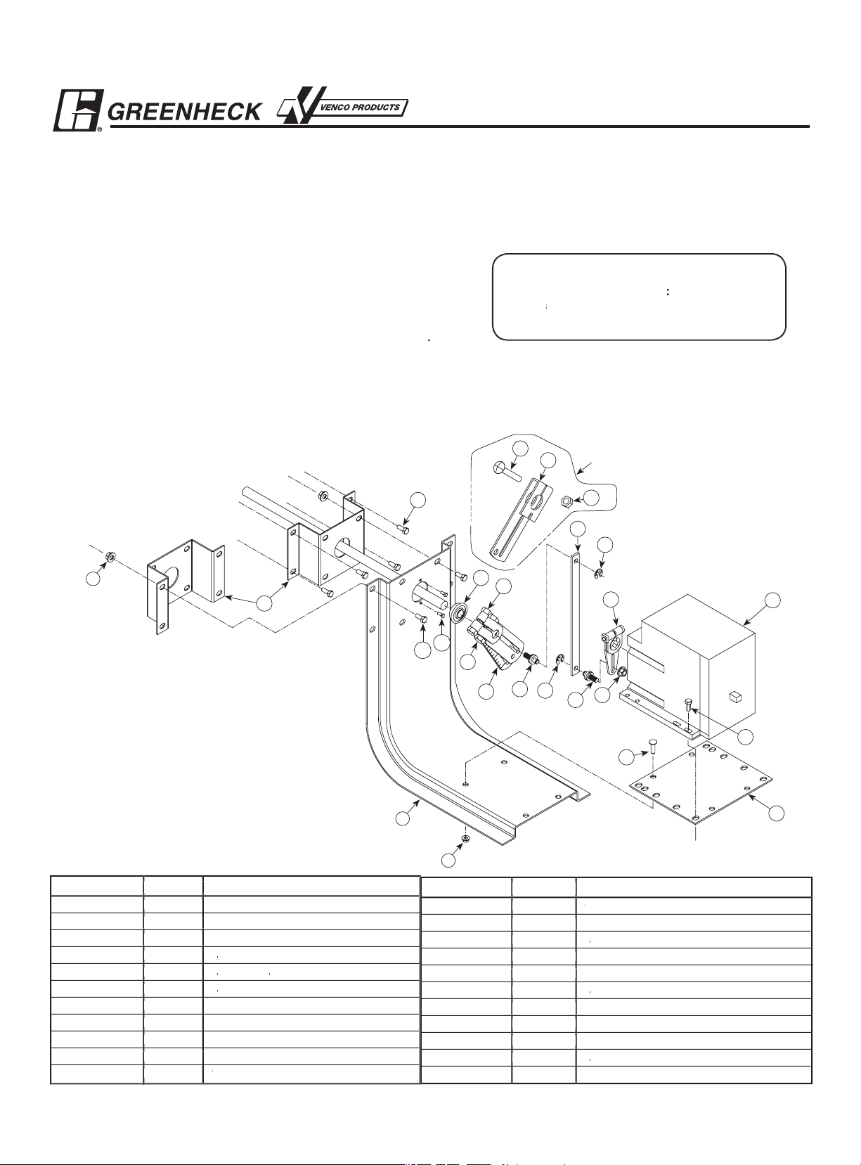
Part Number Quantity Description
3
/
8
-16 Spinlock Nut
13 2 Linkage Adjustment Pin
14 2
1
/
4
in. E-Ring
15 1 Drive Link
16 1 Stand Off Bracket
17 4
1
/
4
in.
-20 x
1
/
2
in. Thread Cutting Screw
18 1 Ball Bearing
19 1 221455A Crankarm
20 2 #10 Tek Screw
1
/
-20 x
1
/
Hex Bolt
Part Number Quantity Description
1 1 Actuator
2 1 Mounting Bracket
3 1 Mounting Plate
1
/
-20 x
1
/
in. Threadstud
5 4
/
-20 x
3
/
in. Threadcutting Screw
6 10
1
/
4
-20 Spinlock Nut
1
/
in. Crankarm
8 2
5
/
16
-18 x 1
/
in. Bolt
9 2
5
/
16
-18 Spinlock Nut
10 1 1 in. Crankarm
3
/
8
-16 x 2
/
in. Carriage Bolt
1
14
15
19
5
3
4
6
13
14
13
7
8
20
21
9
18
17
16
6
2
6
11
10
12
These parts are for
use with a 1 in. shaft
Tools Required:
Wrenches
:
(1
)
3
/
8
, (2
)
1
/
2
, (1)
9
/
16
, (1
)
7
/
16
, and (1)
5
/
16
(1) Hammer
These instructions apply to the external field installation of
that spring returns to the fail position when power is interrupted
The M9185 model actuator, when installed on model FSD fire/
These installation instructions assume the damper is already
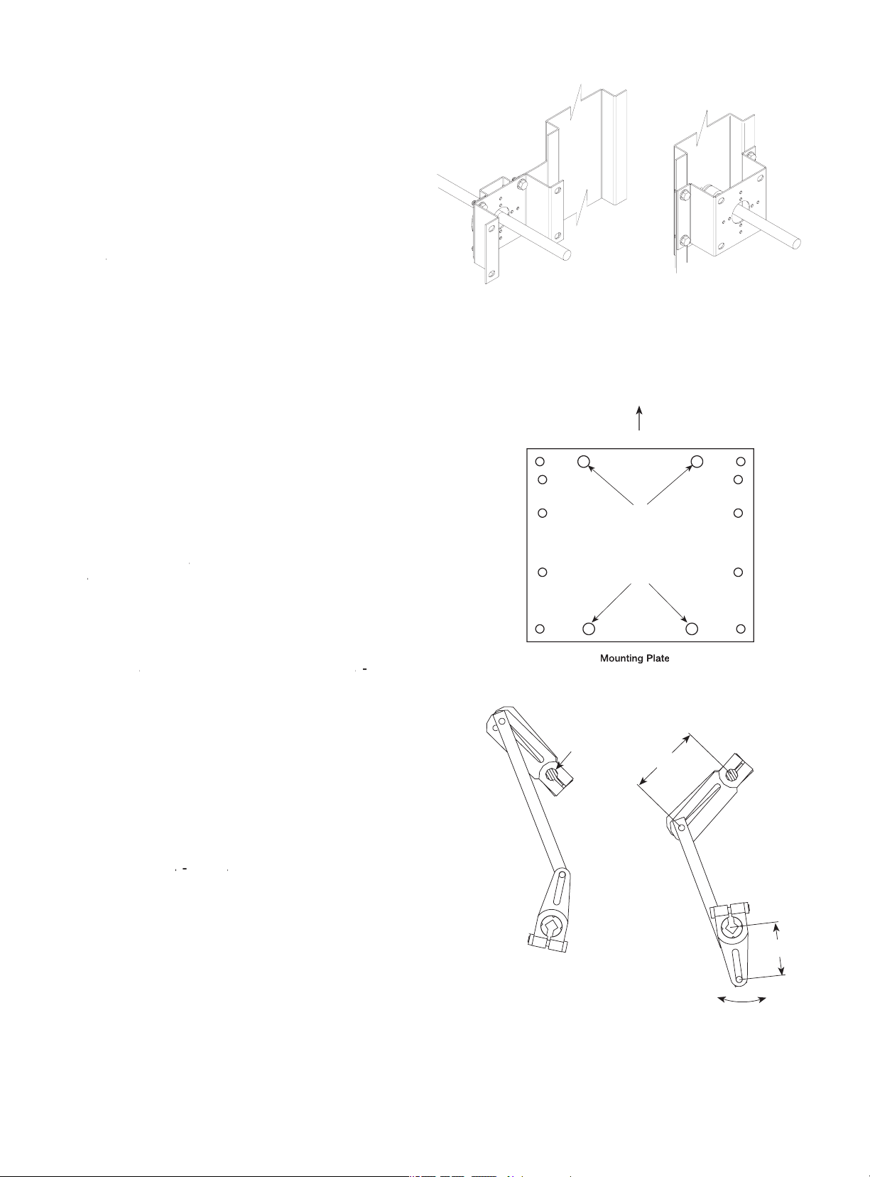
1. Install the stand off bracket (item 16).
Dampers with a jackshaft
1a. Mount the stand off bracket onto the jackshaft bracket with
(4)
/
/
in. thread cutting screws (item 17). Use the
orientation shown on this page.
The bracket must be perpendicular to the damper on
the duct or sleeve and the bracket's shaft hole must be
centered on the jackshaft.
1b. Mount the stand off bracket (item 16) spanning across the
damper frame flanges. Use the orientation shown to the right.
Fasten to the damper frame with (4) #14 Tek screws, supplied
in the field. Be sure not to run the screws into the damper
linkage, which is between the flanges.
The bracket must be perpendicular to the damper on
the duct or sleeve and the bracket's shaft hole must be
centered on the shaft extension.
2. Fasten the mounting plate (item 3) to the mounting bracket
(item 2) using (4)
/
/
in. thread studs (item 4), and (4
)
/
pattern on the mounting bracket labeled “A” on the
illustration. Note that the mounting bracket has only one
pattern that will match the mounting plate pattern.
3. Mount the mounting bracket (item 2) to the stand off bracket
using (4
)
/
/
in. bolts (item 21) and (4
)
/
nuts (item 6) included with this kit. Use the outer four holes of
the mounting bracket for jackshafted models and the inner
four holes for directly driven models.
4. If the damper has a
/
in. dia. damper shaft, mount the ball
bearing (item 18), into the mounting bracket with two #10 Tek
screws (item 20). The Tek screws are required to keep the
thrust forces from pushing the bearing out of the mounting
bracket. If the damper shaft is 1 in. in diameter then no ball
bearing is required.
5. Mount the actuator to the mounting plate in the corresponding
holes using
)
/3/
in. thread cutting screws (item 5).
Note that the actuator must be mounted with the shaft in the
horizontal position.
A
A
3"
Power Position
Fail Position
Return Power
21/8"
Damper
Shaf
t
Counter-Clockwise to
Fail Position

6. Assemble the linkage
Parts needed for dampers with
/
in. shafts:
(Qty.
) / in. crankarms (item 7)
(Qty.
)
5
/
/
in. bolts ( item 8)
(Qty.
)
5
/
(Qty.
(Qty.
) Linkage adjustment pin (item 13)
(Qty.
)
/
4
- 20 spinlock nuts (item 6)
(Qty.
)
/
4
in. E-Ring (item 14)
Parts needed for dampers with 1 in. shafts:
(Qty.
(Qty.
3
/8 /
in. bolts (#11)
(Qty.
3
/
8
(Qty.
(Qty.
) Linkage adjustment pin (#13)
(Qty.
)
/
4
in.
(Qty.
(Qty.
)
/
4
in. E-Ring (#14)
6a. Assemble the shaft crankarms.
For dampers with
/
2
in.
The damper shaft crankarms must be placed as mirror
images of each other, meaning the like sides face each
other. The bolts and nuts are to be positioned as in the
exploded view.
For dampers with 1 in. shafts:
The 1 in. crankarm, item 10, must be in the position
shown in the encircled exploded view shown above left.
Position the bolt and nut as shown in the same diagram.
6b. For dampers with
/
Insert a linkage adjustment pin through both of the
crankarm slots. Position it 3 in. from the center of the
damper shaft. Secure it there with a
/
(item 6).
For dampers with 1 in. shafts:
Insert a linkage adjustment pin through the 1 in. crankarm
(item 10) slot. Position it 3 in. from the center of the
damper shaft. Secure it there with a
/
4
(item 6).
6c. Attach the drive link to the damper shaft crankarms by
inserting the linkage adjustment pin through one of the
drive link’s holes and fastening it with an E-ring (item 14).
6d. Attach the drive link to the actuator crankarm with the
linkage adjustment pin, a spinlock nut and an E- ring
(item 14). Set the linkage adjustment pin 2
/
8
in. from the
actuator shaft center and secure it there with the spinlock
nut. Fasten the other end through the empty drive link hole
with the E-ring (item 14).
7. Note the damper shaft rotation for fail direction and orient
the linkage appropriately as shown in the linkage
illustration. The damper linkage is now in its fail position
Position the damper blades to their proper position (open
or closed). Tighten the bolts
14
15
19
6
13
14
13
7
8
9
11
10
12
with 1 in. shafts
for dampers with
/
3"
Power Position
Fail Position
Return Power
21/8"
Damper
Shaf
t
Counter-Clockwise to
Fail Position
Clockwise to Fail Position
Fail Position
Return Power
3"
21/8"
Power Position

120 v
280v
240v
Com.
White
Violet
Orange
Black
Transformer
T2
T2
R
W
B
T2
T1
Control Device
L1 (Hot)
L2
Transformer
Ye
llow
Red
Blue
Com.
N.C.
N.C.
8. Wire the actuator according to the
appropriate wiring illustration that
identifies the actuator’s electrical
connections. Wiring should be per an
approved project or job wiring diagram
and must comply with all applicable
electrical codes
Note: Tape or wire nut all unused leads.
9. Apply power to the actuator.
The damper blades should fully open or
close and return to the fail position when
power is disconnected, if they do not,
adjustments can be made by resetting
the crankarm position on the damper or
actuator shaft, or by adjusting the 3 in.
dimension on the damper shaft crankarms.
Auxiliary Switch Wiring Connections
with no transformer. Connections must
454200 Honeywell M4182, M8182, M9185 IOM
Voltage
Without Transformer
With Internal Transformer
Auxiliary Switch Ratings (Amperes)
43.2
 Loading...