

Page 1
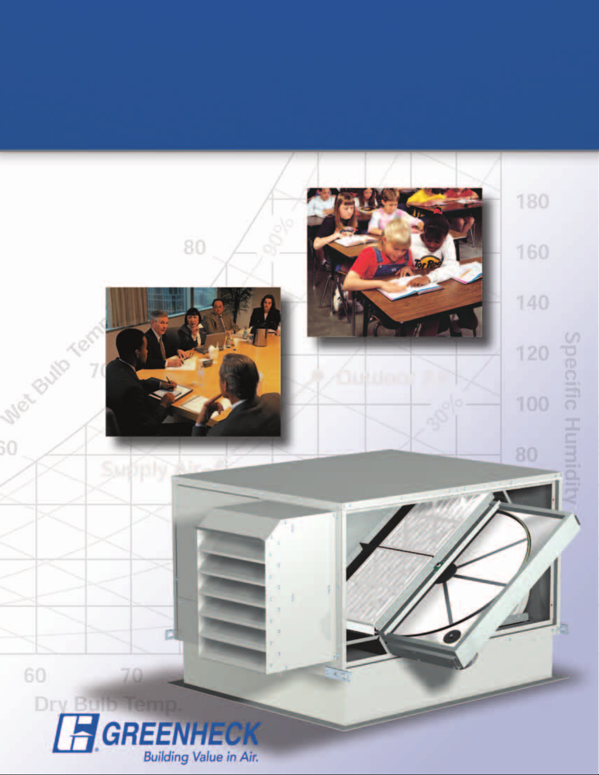
Energy Recovery Ventilator
Model ERV
• Commercial • Institutional
• 400 to 12,000 cfm
• 1.5 in. wg external
static pressure
June
2010
Page 2
Model ERV
Greenheck’s model ERV provides fresh outdoor air to your building and is designed for operation in all climates.
This unit incorporates innovative design features with options in energy wheel performance to provide a quality
constructed unit with performance flexibility. The flexibility and reliability of these units means the ERV will fit
seamlessly into your building to improve your indoor air quality while saving energy and costs.
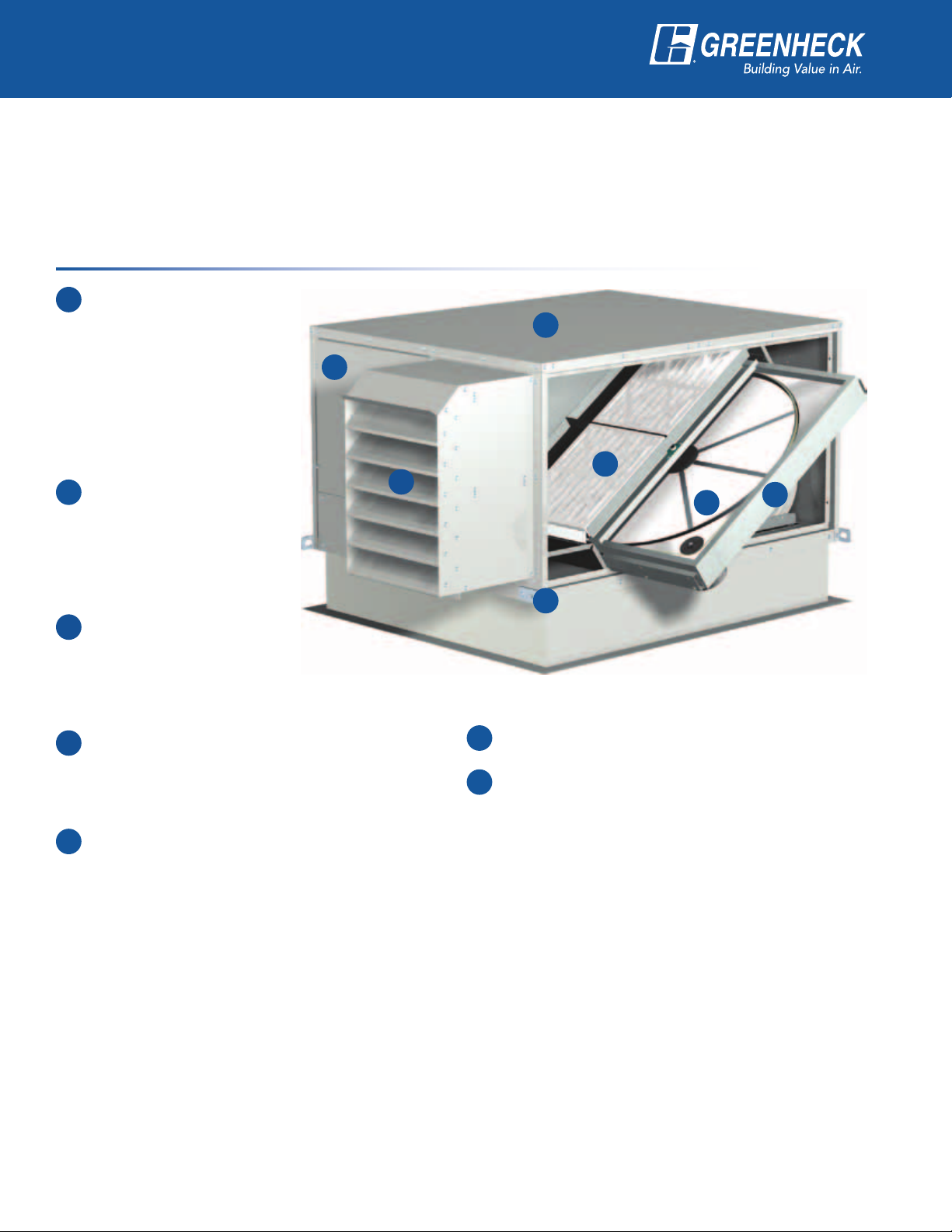
Design Features:
Louvered intake
1
weatherhood lowers
supply air intake
velocities to prevent
rain and snow from
being pulled in to the
unit. Each hood has
washable aluminum
mesh prefilters blocking
debris or leaves.
2-inch outdoor and
2
return air filters with a
MERV 8 (30% efficiency)
rating and are set into
filter racks that permit
easy change out and
rigid support.
Pitched roof and
3
interlocked standing
seams eliminates
standing water
and provides
rigidconstruction.
18 gauge outer wall construction is available in
4
many alternate coatings. Optional double-wall
construction protects insulation from moisture
and prevents insulation fibers from entering the
airstream. Insulation is 3 lb/ft³ density.
Multiple energy wheel options allow selection of a
5
unit by what is critical in the design or application:
• Effectiveness
• Recovery Efficiency Ratio (RER)
• Low blower horsepower
4
1
6
7
3
2
5
6
Integral lifting lugs are included for easy
maneuvering and installation of the unit.
Slide out energy wheel design allows for easy
access to the energy wheel.
7
Additional Features
• Quiet running, forward-curved blowers
• Adjustable motor pulleys for final
systembalancing
• Factory provided motor starters and
disconnectswitch in a sealed control center
• Neoprene isolation on blower assembly to
minimize sound and vibration transmission
• Bolt-on door design allows for fit in tighter
spaces. Optional hinged access is available for
roof mount applications.
2
Page 3
-10 -5 0 5 10 15 20 25 30 35 40 45 50 55 60 65 70 75 80 85 90 95 100 105 110 115 120
50
55
0
5
10
15
20
25
30
35
40
45
ENTHALPY - BTU PER POUND OF DRY AIR
0
10
20
25
30
35
40
45
50
55
60
65
70
75
80
0.350.300.250.20
SENSIBLE HEAT RATIO = Qs / Qt
10
20
30
40
50
60
70
80
90
100
110
120
130
140
150
160
170
15%
25%
2%
4%
6%
8% RELATIVE HUMIDITY
10% RELATIVE HUMIDITY
20%
30%
40%
50%
60%
70%
80%
90%
-5
0
0
5
5
10
10
15
15
20
20
25
25
30
30
35
35
40
40
45
45
50
50
55
55
60
60
65
65
70
70
75
75
80 WET BULB TEMPERATURE - °F
80
85
12.0
13.0
14.0 VOLUME- CU.FT. PER LB. DRY AIR
15.0
HUMIDITY RATIO - GRAINS OF MOISTURE PER POUND OF DRY AIR
Wet Bulb, Saturation Temp - °F
-10 -5 0 5 10 15 20 25 30 35 40 45 50 55 60 65 70 75 80 85 90 95 100 105 110 115 120
DRY BULB TEMPERATURE - °F
0
5
10
15
20
25
30
35
40
45
50
50
55
55
ENTHALPY - BTU PER POUND OF DRY AIR
0
5
10
15
20
25
30
35
40
45
ENTHALPY - BTU PER POUND OF DRY AIR
0.05
0.10
0.15
0.20
0.25
0.30
0.35
0.40
0.45
0.50
0.55
0.60
0.65
0.70
0.75
0.80
0.85
0.90
0.95
1.00
1.05
1.10
1.15
VAPOR PRESSURE - INCHES OF MERCURY
0
10
20
25
30
35
40
45
50
55
60
65
70
75
80
DEW POINT TEMPERATURE - °F
Chart by: HANDS DOWN SOFTWARE, www.handsdownsoftware.com
1.00
0.95
0.90
0.85
0.80
0.75
0.70
0.65
0.60
0.55
0.50
0.45
0.400.350.300.250.20
SENSIBLE HEAT RATIO = Qs / Qt
SENSIBLE HEAT RATIO = Qs / Qt
10
20
30
40
50
60
70
80
90
100
110
120
130
140
150
160
170
15%
25%
2%
4%
6%
8% RELATIVE HUMIDITY
10% RELATIVE HUMIDITY
20%
30%
40%
50%
60%
70%
80%
90%
-5
0
0
5
5
10
10
15
20
25
30
35
40
45
50
50
55
55
60
60
65
65
70
70
75
75
80 WET BULB TEMPERATURE - °F
80
85
12.0
13.0
14.0 VOLUME- CU.FT. PER LB. DRY AIR
15.0
HUMIDITY RATIO - GRAINS OF MOISTURE PER POUND OF DRY AIR
Wet Bulb, Saturation Temp - °F
Chart by: HANDS DOWN SOFTWARE, www.handsdownsoftware.com
15
20
25
30
35
40
45
Model ERV
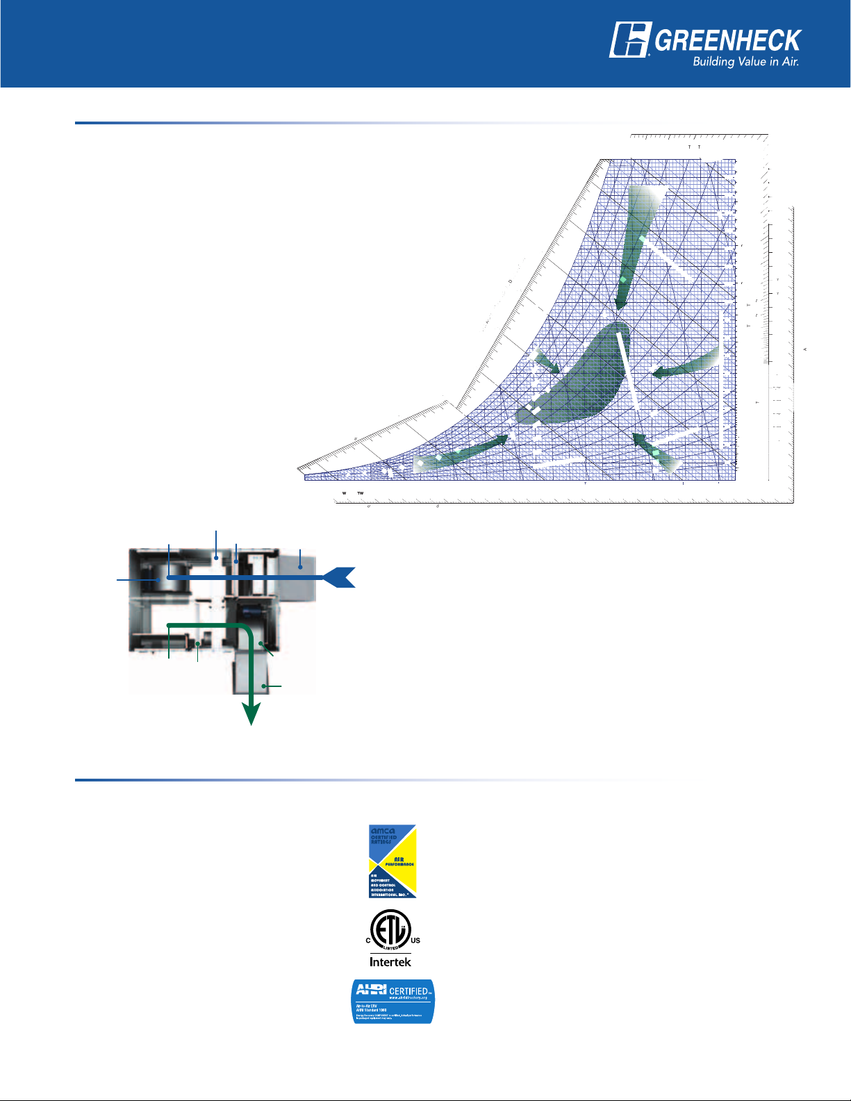
How does an energy recovery wheel work?
The basic objectives for providing acceptable indoor air quality (IAQ) are to
control indoor contaminates levels while maintaining desired indoor air
temperature and humidity. Compliance with the prescribed ventilation rates
in ASHRAE Standard 62 appear to satisfy the contaminant issue. However,
simply increasing outdoor air (OA) requirements with “traditional” HVAC
systems may not address the humidity issue properly and often leads to
significant energy cost increases.
The best solution for most commercial and institutional facilities
will include an enthalpy wheel product. The enthalpy wheel
transfers temperature and moisture properties from one
airstream to another. The result is capturing the cooling and
heating energy before it leaves the HVACsystem.
Moving through the unit, the return and supply airstreams
pass on opposite sides of a divider panel. The
enthalpy wheel rotates between the airstreams
transferring up to 75% of the energy
present in the exhaust airstream to
the supply.
Enthalpy Wheel
Supply Air to Building
Supply
Blower
Filters
Outdoor Air Weatherhood
Outdoor Air
Utilizing an enthalpy wheel to precondition the outdoor air,
narrows the operational range of outdoor air conditions
which the building’s HVAC equipment is designed to
temper. It is this reduction in the outdoor air range that
allows for size reduction in heating and cooling equipment
Return Air From Building
Filters
Exhaust Blower
Exhaust Weatherhood
Exhaust Air
Certifications
ERV’s construction is matched with extensive in-house testing and third-party verification of
performanceandsafety.
Licensed to bear the AMCA seal for
AirPerformance
Unit is ETL Listed — all internal electrical
components are factory wired to a single-point
power connection
ARI Standard 1060 certified energy wheel
performance assures the ERV model will function
as required in demandingenvironments
and reduced energy costs.
Greenheck certifies that the ERV models shown herein are licensed
to bear the AMCA seal. The ratings shown are based on tests and
procedures performed in accordance with AMCA Publication 211 and
comply with the requirements of the AMCA Certified RatingsProgram.
Every unit is tested at the factory before it is shipped to the job site.
Energy recovery wheels are certified by the ARI Air-to-Air Energy
Recovery Ventilation Equipment Certification Program in accordance
with ARI Standard 1060. Actual performance in packaged equipment
may vary. Certified ratings are available in the Certified Product
Directory at http://www.ahridirectory.org/ahridirectory/pages/home.
aspx
3
Page 4
What is the Benefit with
Greenheck Energy Recovery?
For the Building Owner
• Improved Indoor Air Quality (IAQ)
Introducing fresh, outdoor air to a building is a key component to sustaining excellent indoor air quality.
Outdoor air can be very expensive to heat and cool, but the ERV unit can provide an economical approach to
delivering outdoor air into a building.
• Energy Savings = Quick Payback
The energy recovery unit provides energy savings throughout the year. In the summer, the energy recovery
unit removes heat and moisture out of the outdoor air, but in the winter, heat and moisture are added back into
the fresh airstream. When you combine the energy savings from summer and winter operation, they lead to a
very fast payback period. In most parts of the United States, the payback is less than 2 years!
Equipment Reduction Using Energy Recovery on 3000 cfm Outdoor Air
Cooling
Gas Price* Electric Cost**
Boston, MA 1.68 0.1495 8.72 226 161 4544 0.78
Minneapolis, MN 1.14 0.0712 9.55 161 217 3261 0.88
St. Louis, MO 1.34 0.0558 12.1 356 173 3088 0.35
Raleigh, NC 1.48 0.073 11.3 424 138 2790 0.57
Houston, TX 1.10 0.1011 13.0 1701 111 1089 0.22
Tampa, FL 1.59 0.0974 13.1 1779 89 988 0.21
Portland, OR 1.21 0.071 4.17 2 123 2930 2.34
Phoenix AZ 1.13 0.0766 9.40 271 161 1478 1.95
* Average gas price (dollars per therm) per region in the first six months of 2007 (source: Energy Information Administration)
** Average electricity cost (dollars per kWh) in March of 2007 (source: Energy Information Administration)
*** Assumptions: $3/cfm energy recovery cost; $650/ton avoided cooling equipment cost; 75.6% effective energy wheel; 12 hrs/day 5 days/week operation
Equipment
Reduction
(tons)
Annual
Summer
Cooling
Savings
Heating
Equipment
Reduction
(MBH)
Annual Winter
Heating
Savings
Approximate
Payback
(Years)***
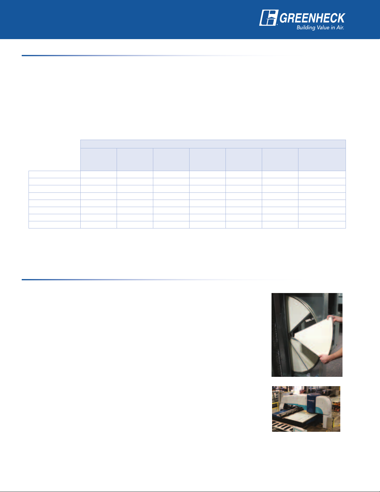
For the Maintenance Personnel
• Low Maintenance Equipment
Energy Wheel: The most important component in the ERV is the energy wheel.
This device should be inspected and cleaned as necessary, which will vary by
application and environment. Any cleaning that is required is simplified by the
easy accessible wheel with removable segments. Cleaning requires no special
equipment (light detergent and water) and can be performed in a location that is
convenient to you.
Fans: The blowers that are used in the ERV are centrifugal, forward-curved- type
fans. These fans come with easily adjustable pulleys, belt tension bolts and
permanently sealed bearings.
Filters: The 2-inch, 30% efficient MERV 8 filters that are included with the unit are
designed for easy access and removal.
• Quality Construction
Greenheck has focused on the manufacturing and unit designs to create well-
constructed equipment. Investments in automated manufacturing processes
provide accurate and repeatable results, giving excellent part fit and unit strength.
Incorporation of innovative designs add to the quality, while keeping maintenance
work simple to perform.
• Long-Lasting Equipment
Because of our high-quality construction, the equipment that goes to the field is made to last. As reassurance
to the customer, each ERV unit carries a 1-year warranty from the ship date and the wheel components
(segments, cassette, belt, and pulleys) carry a 5-year warranty.
4
Page 5
What is the Benefit with
Greenheck Energy Recovery?
For the Design Engineer
• Adhering to ASHRAE Guidelines
ASHRAE Standard 90.1 provides design guidelines regarding when it is most beneficial to use energy
recovery. Depending upon your geographic location and the percentage of outdoor air in the application,
ASHRAE recommends when to use energy recovery. An important part of this guideline is that when energy
recovery is recommended, the device should be a minimum of 50% total (sensible and latent) effectiveness
according to ARI 1060 testing procedure.
ASHRAE Standard 189.1 provides high performing building design guidelines. This requires even higher energy
recovery device performance than Standard 90.1. When energy recovery is recommended, the device shall be
a minimum 60% total (sensible and latent) effectiveness according to ARI 1060 testing procedure.
• LEED Certification Credits
For Green Building designs, the ERV offers an excellent way to acquire credits in both
Energy and Atmosphere (EA) and Indoor Environmental Quality (EQ) categories towards a
LEED certification.
• CAPS Program
CAPS is Greenheck’s comprehensive product selection program. The CAPS program was
developed with ease of use and fast selections in mind. There is also useful information
available for making selections and educating people who are new to energy recovery
technology. CAPS also provides submittals which includes unit overview, electrical
information, fan charts, arrangements, engineering drawings, payback information, and
psychrometric processes.
• CSI Specifications
After a unit has been selected in CAPS, an accurate unit specification is available for use in the job
specification. These specifications have been recently updated to the CSI format.
• Industry Certification
To ensure performance on the job site, Greenheck emphasizes the need for the 3 major industry certifications
for energy recovery units: AMCA Licensed for Air Performance, ETL Listed for safety, and ARI Certification on
the energy recovery wheel.
Prepared to Support
Green Building Efforts
For the Contractor
• Easy Installation
- Lifting Lugs
- Single-Point Power
- Bolt-doors for limited clearance applications
These are just a few of the built-in features to make the installation process quick and easy. Our
comprehensive Installation, Operation, and Maintenance Manuals are also available online, so the information
you need is quick and easy to obtain.
• Product Approval
Form, fit and function, the ERV was designed to operate in commercial and institutional applications. With over
a decade of installations specific to the energy recovery market, Greenheck’s energy recovery product line is
well known and accepted throughout the industry.
• 1 — 5-Year Warranty
Our 1-year unit warranty and 5-year energy recovery wheel warranty lets you to rest easy knowing that we
stand behind our product.
Lifting Lugs
5
Page 6

Accessories
Low-Leakage Dampers — Internally mounted for
both supply and exhaust
Where code requires low-leakage
dampers they can be provided to keep
the cold weather out in the winter,
or hot and humid weather out during
the summer. Since the dampers are
wired to a single-point power source,
a simple run command sent to the
unit powers the dampers open. When your unit is off
during unoccupied hours, the dampers close to keep
the outdoor air out.
Filters
Standard size 2-inch pleated, medium efficiency filters
and filter racks are available for supply and/or exhaust
airstreams.
Model Filter Size Quantity
ERV-251 16 x 25 1
ERV-361 16 x 20 2
ERV-521 16 x 25 3
ERV-581 16 x 20 6
ERV-522 16 x 25 7
All dimensions shown in inches.
Roof Curbs
For a cohesive fit between
the ERV and your building,
Greenheck offers a preengineered curb design. They
are available with duct adaptors
to simplify field duct installation
and get the unit up and running morequickly.
Double Wall Construction
The supply and exhaust side are internally lined with
20 gauge galvanized steel.
Weatherhoods
A louvered intake hood with 2-inch aluminum mesh
filters and exhaust hood with an integral backdraft
damper are available.
Hinged Access Doors
Panel side doors are a standard feature on all
units. Hinged access doors are available on models
ERV-361, -521, -581, -522, and -582. Access doors
are removable hinge type with lift and turn latches for
access to internal components.
Air Filtration — High-Efficiency Filters
Unit is standard with 2-inch, MERV 8,
30% efficient filters. Optional MERV 13,
85% efficient filters are available to help
meet additional LEED requirements or
simply improve indoor air quality.
Painted Exterior
For added aesthetics and a
long-lasting finish, Greenheck
offers many different paint
DESERT
SAND
PERMATECTOR™
options. Pre painted coatings
in either Gray or Desert Sand
offer economical options in customizing your unit. If
a more specific color is desired, we also offer a wide
variety of colors to meet your specific needs.
Remote Panel
With the optional remote panel you have control and
the information you want. Monitoring lights, on/off
time-clock control, or on/off/auto switch are a few of
the available options. So whether you want to control
the unit operation via a 7-day time clock or simply
want to monitor unit performance, the remote panel is
the option that you’ll need.
6
Page 7

Accessories
Dirty Filter Sensors
Filters require scheduled maintenance to improve
air quality and system efficiency. A dirty filter sensor
allows you to minimize maintenance frequency to only
when it is needed. The dirty filter kit senses when
the filters are dirty and sends a signal to our built-in
control center. Greenheck offers an optional remote
control panel and a “clogged filter” light to tie the
signal into.
Rotation Sensor
Adding a wheel rotation sensor to the unit assures
you that the energy wheel is operating properly. The
sensor sends a signal to the control center of the
unit in the rare event that the wheel stops rotating.
Greenheck offers an optional remote control panel and
a “wheel rotation” light to tie the signal into.
Factory Mounted Sensors
Amp Draw, Pressure, Temperature: Greenheck offers
factory mounted sensors that are wired back to the
control center, so you can get the information you
need to know, exactly where you need to measure
it. These sensors can be used to simply monitor unit
operation or to actively control the unit with controls
by others.
Amp Monitor
Blower amp draw can be monitored
through the use of an amperage
sensor. These sensors allow for
either an analog or digital output
based on your system needs.
CO2 Sensor
A good indicator for building health is
carbon dioxide (CO2). Greenheck offers a
CO2 sensor, that can be used to engage
the unit based on CO2 levels, or it can
increase or decrease airflows through
the use of a variable frequency drive
(VFD) on the blowers. The CO
can be unit mounted or space mounted
depending on your application.
Service Outlet
While performing minimal maintenance on your ERV, a
service outlet can provide power when and where it’s
needed. Shipped loose, the outlet can be mounted in
the correct location for your building.
Vapor-Tight Lights
Access doors provide natural lighting during the day,
but there may be times when more light is needed
to see properly inside the unit. To increase bulb life
and to also protect the bulb, Greenheck offers a
vapor-tight light.
Blower VFD’s
Variable frequency drives are a great
tool to control airflow to the space
or to maintain duct pressures. With
this optional feature, two VFD’s are
utilized, one per fan for independent
andflexiblecontrol.
sensor
2
Wheel Pressure Sensors
In each airstream, a pressure
sensor is available to monitor
wheel operation. Wheel pressure
can be used to indicate a buildup
of frost during the cold winter
months or can be used as a CFM
gauge as the energy wheel is a
laminar flow device (i.e. a specific
pressure equals a specificCFM).
Temperature Sensors
Wheel performance can be
determined with factory mounted
temperature sensors. Every
compartment can be monitored to
know how your unit is operating.
7
Page 8

Accessories
Economizer Control (Free Cooling)
Take advantage of cool outdoor air to handle space loads. A call for cool air is sent to the unit’s control center
which triggers one of a few different options to bring in fresh cool air:
Energy Wheel On/Off
The wheel cycles off when it’s in the free cooling range (temperature or enthalpy), and
cycles on when outdoor air is too warm or too cold. This option is recommended when the
air is being supplied to an air handling unit or duct heater, and not directly to the space.
Energy Wheel Modulation
The wheel speed modulates to maintain a 55°F discharge temperature. Above 55°F,
the wheel is off up to a high-limit temperature setting (typically 70°F). This option is
recommended when the air is supplied directly to the space from the ERV or when more
precise temperature control is needed.
Frost Protection
Cold climates, in combination with higher indoor humidity levels, may cause frost to form on the energy wheel
during normal operation. To protect against frost, we measure the outdoor temperature and the energy wheel
pressure drop. When it’s cold enough and the wheel pressure is increasing, the wheel is frosting. Only then will
the frost methods described below engage. See the “Frost Control Strategy Recommendations” chart on this
page for which of the three Greenheck frost methods we recommend for your building.
Timed Exhaust Frost Control
The supply blower cycles on and off based on a
factory provided timer. With the supply blower
off, the warm exhaust air melts the frost. Once the
wheel pressure decreases, the supply blower turns
Winter Outside Air
backon.
Modulating Wheel Frost Control
A factory installed variable frequency drive (VFD)
≥ 10°F (-12.2°C) ≤ 50% RH None
≥ -5°F (-20.6°C) <
slows the wheel down making it less effective.
In other words, the slow rotating wheel spends
enough time in the warm exhaust airstream to melt
≥ 10°F (-12.2°C) ≤ 50% RH
≥ -5°F (-20.6°C) <
the frost. Once the wheel pressure decreases,
it returns to full speed. Both blowers operate
continuously during this frost mode. Modulating
wheel frost control is available on all sizes except
the ERV-251.
Preheat Frost Control
An electric preheater is built into the ERV outdoor air intake. When frost occurs, the heater engages, and
increases the outdoor air temperature above the frost threshold to melt the wheel. Once the pressure
decreases, the heater shuts off.
Frost Control Strategy Recommendations
Winter Indoor Air
Design
10°F (-12.2°C)
10°F (-12.2°C)
≥ -5°F (-20.6°C) Any RH
Design
≤ 35% RH Timed Exhaust
≤ 35% RH
Recommended
Frost Control
Strategy
Electric Preheat
The map at left indicates the frost control
options, if any, that are appropriate based
on climactic conditions during typical
16hour per day operation.
Preheat Frost Control Recommended*
Timed Exhaust Frost Control Recommended*
No Frost Control Needed
*Modulating Wheel Frost Control can also be used in these areas.
8
Page 9

Arrangements
Top View
Supply Air
Exhaust Air
Interior
This compact design is ideal for the space limitations
that routinely complicate interior installations.
Arrangement A
Specify Arrangement A for interior mounting. All ERV
sizes are available in this arrangement. Fig.1 is typical
for ERV-251, -361, -521, and -581.
Exterior
Where roof mount or pad mount installations are
preferred, Greenheck offers three arrangements to
provide the flexibility to simplify system design and
installation. Louvered intake hood and an exhaust hood
are standard on Arrangements B, C and D. The housing
and hood design minimize re-entrainment of exhaust
air.
Top View
Supply Air
Exhaust Air
Fig. 1
Arrangement A - Interior Mounted
Top View
Arrangement B
Ideal for roof mount installations where both exhaust and
supply ducts penetrate the roof deck and attach to the
bottom of the energy recovery ventilator. Fig. 2 is typical
for ERV-251, -361, -521, and -581.
Arrangement C
Ideal for roof mount installations where the supply
airstream is to be routed directly into a rooftop HVAC
unit. Exhaust air enters the ERV from below.
Arrangement D
Suited for pad mounting, where both the exhaust and
supply ducts connect to the end of the ERV.
Supply
Air
Fig. 2
Exhaust
Hood
Exhaust Air
Intake Hood
Arrangement B - Roof Mounted
9
Page 10

Dimensions
Arrangement A Arrangement B
ERV-251, ERV-361, ERV-521, ERV-581
Model
ERV-251 46 34 27 12 8 10 16 6
ERV-361 62 51 34 18 15 18 18 8
ERV-521 67 67 44 16 15 24 24 10
ERV-581 75 70 67 16 22 22 27 16 18
Exterior Dimensions Duct Dimensions
A B C D E F G K L Q P
3
⁄4 7 10 16 340
3
⁄8 111⁄2 19 18 860
3
⁄4 131⁄2 26 26 1290
3
⁄4 28 48 1470
All dimensions shown are in inches. Weight assumes outdoor unit with filters, weatherhoods, and supply damper.
Outdoor Air Discharge
Exhaust Air Inlet
F x G
Arrangement A
L x K
Outdoor Air Inlet
Q x P
Outdoor Air Discharge
L x K
C
C
Arrangement B
B
A
E
Exhaust Air Inlet
F x G
Exhaust Hood
Intake Hood
Exhaust Air Discharge
L x K
A
B
Weight
(lbs.)
D
Arrangement C Arrangement D
Outdoor Air Discharge
L x K
C
Exhaust Air Inlet
F x G
B
E
Exhaust Hood
A
D
Intake Hood
Service Clearance
Installation must allow clearance for access to the energy
recovery wheel on the supply side. Minimum clearances
are shown in the table at right. Page 4 shows the side
panel that enables wheel access.
Outdoor Air Discharge
L x K
B
C
Exhaust Air Inlet
F x G
Exhaust Hood
Model
Supply Side
ERV-251
ERV-361
ERV-521
ERV-581
All dimensions shown are in inches.
E
32
44
60
65
A
D
Intake Hood
Exhaust Side
30
30
40
40
10
Page 11

Dimensions
Arrangement C
Arrangement D
Arrangement A
Arrangement B
ERV-522 and ERV-582
Model
Exterior Dimensions Duct Dimensions
A B C D E F G H J K L Q P
ERV-522S 124 84 64 16 19 48 25 26 36 16 18
5
⁄8 60 25 3230
Weight
(lbs.)
ERV-522H 124 84 64 16 19 48 25 26 36 19 22 60 25 3230
1
ERV-582H 146 97 77 17
⁄2 263⁄4
All dimensions shown are in inches. Weight assumes outdoor unit with filters, weatherhoods, and supply damper.
Arrangement A
Outdoor Air Discharge
Outdoor Air Inlet
Q x P
C
Exhaust Air Discharge
L x K
B
A
60 28 31 38 23 25 70 30 3700
Arrangement B
L x K
Exhaust Air Inlet
F x G
C
Intake Hood
Exhaust Air Inlet
H x J
B
E
D
A
Exhaust Hood
Outdoor Air Discharge
L x K
Arrangement C Arrangement D
Outdoor Air Discharge
E
A
Exhaust Hood
L x K
C
Intake Hood
Exhaust Air Inlet
H x J
B
D
Service Clearance
The installation must allow clearance for access to
the energy recovery wheels and servicing. Minimum
clearances are shown in the table at right. Model ERV522 and ERV-582 energy wheels are mounted in an
upright position, side by side. For servicing, the energy
wheels slide out of the ventilator at opposite corners.
11
C
Intake Hood
Model
B
D
Supply Side
ERV-522
ERV-582
All dimensions shown are in inches.
38
42
Outdoor Air Discharge
L x K
E
A
Exhaust Hood
Exhaust Side
38
42
Exhaust Air Inlet
F x G
Page 12

NOTES:
1. Performance tables show EXTERNAL
static pressure capabilities.
2. Bhp, watt and amp values shown are for
one blower motor only.
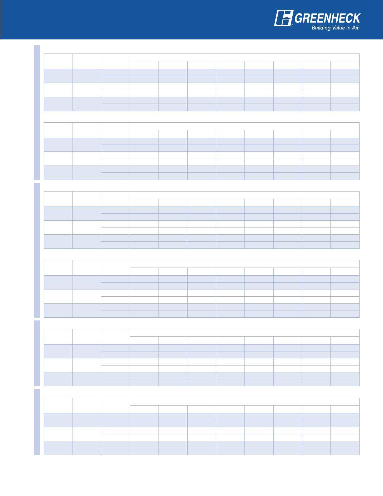
Performance
Supply and Exhaust - Belt and Direct Drive
The airflow performance data shown
applies to arrangement A and is licensed to
bear the AMCA Seal for Air Performance.
Performance data for other arrangements
may differslightly.
For specific performance for all arrangements,
use Greenheck’s Computer Aided Product
Selection (CAPS) program.
All models are available in A, B, C, and
Darrangements.
ERV-251S (Standard Airflow)
Nominal
RPM
950 3.0/1.5 300 563 536 498 450 378
1150 5.3/2.7 530 700 680 658 634 597 513
1350 8.6/4.3 855 834 818 801 783 762 711 642
ERV-251H (High Airflow)
Nominal
RPM
1150 5.0/2.5 500 802 777 742 706 667
1340 8.1/4.1 810 958 937 915 887 857 792
Model ERV-251 / Direct Drive
1520 11.5/5.8 1150 1089 1070 1051 1032 1008 954 895
Max Amps
115/230
Max Amps
115/230
Max. Watts
(input)
CFM
Max. Watts
(input)
CFM
Greenheck Fan Corporation certifies that the
ERV models shown herein are licensed to bear
the Air Performance AMCA seal. The ratings
shown are based on tests and procedures
performed in accordance with AMCA Publication
211 and comply with the requirements of the
AMCA Certified Ratings Program.
EXTERNAL STATIC PRESSURE (in. wg)
0.25 0.375 0.50 0.625 0.75 1.00 1.25
EXTERNAL STATIC PRESSURE (in. wg)
0.25 0.375 0.50 0.625 0.75 1.00 1.25
ERV-361S (Standard Airflow)
CFM OV
1000 1495
1200 1794
1400 2093
1600 2392
ERV-361H (High Airflow)
CFM OV
1600 2392
Model ERV-361 / Belt Drive
1800 2691
2000 2990
2200 3289
Gross supply air performance ratings (airflow, pressure, and power) are at port 2 with port 1, port 3 and port 4 at 0.0 in. wg. Gross exhaust air
performance ratings (airflow, pressure, and power) are to port 3 with port 1, port 2 and port 4 at 0.0 in. wg. Power rating (Bhp) does not include drive
losses. Performance ratings do not include the effects of appurtenances in the airstream.
FRPM 777 863 941 1015 1147 1277 1397 1515
BHP 0.21 0.25 0.29 0.33 0.41 0.49 0.58 0.69
FRPM 899 974 1043 1109 1232 1343 1453 1557
BHP 0.34 0.39 0.43 0.48 0.58 0.68 0.78 0.87
FRPM 1023 1091 1153 1212 1324 1429 1527 1618
BHP 0.52 0.58 0.64 0.68 0.80 0.92 1.03 1.14
FRPM 1149 1212 1269 1323 1424 1520 1613 1701
BHP 0.75 0.82 0.89 0.95 1.07 1.20 1.34 1.47
FRPM 1006 1065 1122 1175 1275 1367 1457 1542
BHP 0.58 0.64 0.69 0.74 0.86 0.96 1.07 1.19
FRPM 1119 1172 1223 1272 1365 1452 1533 1613
BHP 0.82 0.88 0.93 0.99 1.12 1.25 1.36 1.49
FRPM 1232 1279 1326 1372 1458 1541 1618 1692
BHP 1.11 1.17 1.23 1.30 1.43 1.58 1.72 1.85
FRPM 1347 1389 1433 1474 1555 1633
BHP 1.46 1.53 1.60 1.67 1.81 1.97
0.125 0.250 0.375 0.50 0.75 1.00 1.25 1.50
0.125 0.250 0.375 0.50 0.75 1.00 1.25 1.50
EXTERNAL STATIC PRESSURE (in. wg)
EXTERNAL STATIC PRESSURE (in. wg)
12
Page 13
Performance
Supply and Exhaust - Belt Drive
ERV-521S (Standard Airflow)
CFM OV
2,200 2,183
2,700 2,679
3,200 3,175
ERV-521H (High Airflow)
CFM OV
Model ERV-521
3,100 3,076
3,700 3,671
4,300 4,267
ERV-522S (Standard Airflow)
CFM OV
5,000 2,416
5,750 2,779
6,500 3,141
FRPM 830 881 933 981 1072 1155 1238 1315
BHP 0.72 0.80 0.87 0.95 1.09 1.25 1.41 1.57
FRPM 998 1040 1081 1124 1203 1278 1350 1416
BHP 1.29 1.38 1.47 1.57 1.75 1.93 2.12 2.30
FRPM 1168 1203 1240 1274 1345 1412 1477
BHP 2.11 2.21 2.32 2.43 2.65 2.86 3.08
FRPM 980 1017 1054 1089 1159 1226 1290 1355
BHP 1.57 1.65 1.73 1.82 1.99 2.18 2.36 2.54
FRPM 1156 1187 1219 1249 1309 1367 1425 1480
BHP 2.62 2.72 2.83 2.92 3.12 3.33 3.55 3.77
FRPM 1334 1361 1388 1415 1467 1519 1569
BHP 4.08 4.20 4.31 4.43 4.65 4.89 5.13
FRPM 754 794 831 869 943 1011 1072 1134
BHP 2.20 2.39 2.57 2.76 3.15 3.54 3.89 4.30
FRPM 855 892 924 957 1022 1087 1146 1201
BHP 3.28 3.49 3.70 3.92 4.33 4.81 5.26 5.67
FRPM 956 991 1021 1049 1108 1164 1222 1276
BHP 4.67 4.90 5.15 5.39 5.88 6.33 6.89 7.41
0.125 0.25 0.375 0.50 0.75 1.00 1.25 1.50
0.125 0.25 0.375 0.50 0.75 1.00 1.25 1.50
0.125 0.25 0.375 0.50 0.75 1.00 1.25 1.50
EXTERNAL STATIC PRESSURE (in. wg)
EXTERNAL STATIC PRESSURE (in. wg)
EXTERNAL STATIC PRESSURE (in. wg)
ERV-522H (High Airflow)
CFM OV
Model ERV-522
6,000 2,067
7,500 2,584
9,000 3,100
ERV-581H (High Airflow)
CFM OV
4,300 2,064
5,050 2,424
Model ERV-581
5,800 2,784
ERV-582H (High Airflow)
CFM OV
9,000 2,254
10,500 2,630
Model ERV-582
12,000 3,005
Gross supply air performance ratings (airflow, pressure, and power) are at port 2 with port 1, port 3 and port 4 at 0.0 in. wg. Gross exhaust air
performance ratings (airflow, pressure, and power) are to port 3 with port 1, port 2 and port 4 at 0.0 in. wg. Power rating (Bhp) does not include drive
losses. Performance ratings do not include the effects of appurtenances in the airstream.
FRPM 535 581 619 660 731 797 857 913
BHP 1.57 1.79 1.96 2.16 2.55 2.94 3.33 3.72
FRPM 646 686 722 753 818 877 930 983
BHP 2.90 3.20 3.46 3.68 4.17 4.66 5.12 5.62
FRPM 763 794 827 857 910 964 1016 1063
BHP 4.90 5.20 5.57 5.89 6.42 7.01 7.60 8.18
FRPM 637 687 733 772 850 923 988 1055
BHP 1.20 1.35 1.49 1.61 1.88 2.16 2.42 2.73
FRPM 731 774 817 855 922 989 1053 1111
BHP 1.89 2.05 2.23 2.39 2.68 3.00 3.33 3.65
FRPM 826 866 903 939 1004 1061 1120 1177
BHP 2.79 2.99 3.18 3.38 3.74 4.07 4.44 4.83
FRPM 595 629 661 692 746 797 843 888
BHP 3.61 3.95 4.26 4.54 5.25 5.89 6.48 7.09
FRPM 685 713 741 769 820 867 911 952
BHP 5.60 5.99 6.38 6.74 7.44 8.27 9.03 9.74
FRPM 776 800 825 849 897 941 982
BHP 8.24 8.66 9.12 9.56 10.36 11.19 12.13
0.125 0.25 0.375 0.50 0.75 1.00 1.25 1.50
0.125 0.25 0.375 0.50 0.75 1.00 1.25 1.50
0.125 0.25 0.375 0.50 0.75 1.00 1.25 1.50
EXTERNAL STATIC PRESSURE (in. wg)
EXTERNAL STATIC PRESSURE (in. wg)
EXTERNAL STATIC PRESSURE (in. wg)
13
Page 14

Selection Guidelines
Motor Specifications
Blower motor information
must be specified to select
unit. The horsepower,
voltage, phase and enclosure
availability is presented
in the table on the right. If
exhaust and supply blower
horsepower are different,
consult the CAPS program.
Model
ERV-251S*
ERV-251H*
115/1 230/1 230/460/3 230/1 230/460/3 230/1 230/460/3
1
⁄4
1
⁄2
ERV-361* -
ERV-521* ERV-581* - - 1 - 5 - 1 - 5 - 1 - 3
ERV-522* - 1
Open TE Two Speed Open
1
⁄4 - - - - -
1
⁄2 - - - - -
1
⁄4 - 2
1
⁄2 - 3
1
⁄2 - 3 11⁄2 - 15 11⁄2 1 - 15 - 1 - 71⁄2
1
⁄4 - 2
1
⁄2 - 51⁄2 - 11⁄21⁄2 - 5
1
⁄4 - 2
1
⁄4 - 2
1
⁄2 - 11⁄2 - 11⁄2
1
⁄2 - 1
1
⁄2 - 3
ERV-582* - - 11⁄2 - 15 - 1 - 15 - 1 - 71⁄2
UL Listing is available on most open drip proof motors.
*Energy wheel drive motor is only available with open drip proof motors
.
Minimum Circuit Amps (MCA) Calculations for ERV Units
Wheel drive, 24 volt internal control amp and standard electric preheat kW. Single or three phase ERV units
Wheel Drive Amps
Model
115 208/230 460 115/1 208/1 230/1 208/3 230/3 460/3
ERV-251 0.6 0.6 NA 0.5 2.5 2.1, 4.1 2.5, 5 NA NA NA
ERV-361 NA 1.2 0.6 1 NA NA NA 4.1, 8.2, 12.3 5, 10, 15 5, 10, 15
ERV-521 NA 2.8 1.4 1 NA NA NA
24v
Control
Amps
Standard Electric Preheat kW
8.2, 12.3,
15.5
10, 15, 19 10, 15, 20, 25, 30
ERV-581 NA 1.6 0.8 1 NA NA NA 12.3, 15.5 15, 19 15, 20, 25, 30, 38
ERV-522 NA 5.6 2.8 1 NA NA NA 15.5 19 20, 25, 30, 45
ERV-582 NA 3.2 1.6 1 NA NA NA 15.5, 24.5 19, 30 20, 38, 50
NA = not available
MCA Example Calculation
Greenheck ERV selected: ERV-361S-B, 2 hp
supply motor, 11⁄2 hp exhaust motor, 15kW
preheater operating at 460 volt, three phase.
Step 1: Consult NEC table (not shown) for 2 hp
Model CFM
supply motor amps = 3.4 A
Step 2: Consult NEC table (not shown) for 11⁄2 hp
exhaust motor amps = 2.6 A
Step 3: Calculate 15kW preheater amp draw =
15,000W/ [460 * 3 ] = 18.8 A
ERV-251
ERV-361
If no preheater is used skip step 3
Step 4: Wheel drive amps for ERV-361 from
table above = 0.6 A
Step 5: 24v Control Amps for ERV-361 from
table above = 1.0 A
ERV-521
ERV-581
ERV-522
Step 6: MCA = Amperage total from steps
1 thru 5 x 1.25
ERV-582
MCA = (3.4 + 2.6 + 18.8 + 0.6 + 1.0)
1.25 = 33 A
Note: Calculations are approximate, use our Computer Aided Product Selection (CAPS) program for exact
MCA calculations.
Filter Pressure Drop
Intake Hood
with 2-inch
aluminum
filters
Pleated
2-inch
filters
500 0.09 0.09
1,000 0.32 0.19
1,000 0.09 0.10
2,200 0.45 0.28
2,500 0.13 0.14
4,500 0.45 0.32
4,500 0.17 0.15
5,500 0.30 0.24
6,000 0.15 0.14
9,000 0.40 0.25
9,000 0.13 0.16
12,000 0.45 0.27
14
Page 15

Typical Applications
The ERV unit can add to the benefit of a building design anywhere that outdoor air is required and the exhaust
air is considered “clean” (ASHRAE class 1 or class 2 air ratings). Some examples of commercial and institutional
applications where energy recovery units have been utilized are given below.
Animal Shelters Bars and Clubs Churches Dormitories
Locker Rooms Nursing Homes Office Buildings Printing Shops
Restaurants Schools Function Halls Casinos
Veterinary Hospitals
With Ducted Air Handlers
The ERV unit may be combined with ducted air handling units or fan coil boxes. A single energy recovery
ventilator may provide fresh outdoor air for multiple air handling units or in a one-to-one ratio where a single
energy recovery ventilator and air handler serve one space.
AIR HANDLING
UNIT (AHU)
Heating
Coil
Cooling
Coil
72°F 50% 72°F 50%
ZONE 1 ZONE 2
With Packaged Rooftop Equipment
This diagram illustrates how energy recovery
ventilators may be used in conjunction
with packaged rooftop equipment. Fresh,
outdoor air enters the energy recovery
ventilator and is pretreated before entering
the heating/cooling equipment. This
pretreating occurs because the energy
recovery wheel is transferring latent and
sensible energy between the outdoor air and
the building exhaust air.
Heating
Coil
Cooling
Coil
SUPPLY AIR
AHU
RELIEF AIR
Exhaust
Fan
RESTROOM
EXHAUST
AIR
OUTDOOR AIR UNIT (OA unit)
RESTROOM
WITH ENERGY RECOVERY
Energy
Wheel
Exhaust
Fan
EXHAUST AIR
ZONE 1
72°F
50%
AIR HANDLING
UNIT (AHU)
OUTDOOR
AIR
Energy
Wheel
ENERGY RECOVERY
VENTILATOR (ERV)
Supply
Fan
15
Heating
Coil
SUPPLY AIR
Cooling
Coil
Page 16

Greenheck’s Energy
Recovery Models
Model MiniVent - Energy Recovery Ventilator
The MiniVent-450 & 750 are energy recovery ventilators
used for commercial and institutional applications that
require 300 to 800 cfm of ventilation air. The compact
design provides an economical solution for individual
spaces, such as school classrooms and small offices.
Model ERH - Energy Recovery with Heating
With the ERH, you save money with the total energy wheel
and get the convenience of supplemental heating. The ERH
provides preconditioned air in the summer and space neutral
air in the winter, which is ideal if your climate has prominent
summer and winter seasons. The heating section further
tempers cold outdoor air to desired conditions. Four housing
sizes available with airflow capacities up to 10,000 cfm and
external static pressures up to 1.5 in. wg.
Model ERCH - Energy Recovery with Cooling and Heating
The model ERCH combines the benefits of the total energy wheel with
supplemental cooling and heating. The result is a product that is specifically
designed to process 100% outdoor air to desired supply conditions. Four housing
sizes provide airflow capacities from 1,000 to 10,000 cfm with external static
pressures up to 1.5 in. wg. A variety of tempering options are available. The coil
section of the ERCH accommodates a cooling coil, a heating coil, or both.
Model VER - Versatile Energy Recovery (VersiVent)
The Model VER is a fully featured, versatile energy recovery unit with a wide
range heating and cooling options available. The unit includes an
energy wheel to pre temper the outdoor air which reduces the heating
and cooling equipment needed, while also lowering operational costs.
In addition to the standard heating and cooling options, the VersiVent
has options such as environmentally friendly R410 refrigerant, a wraparound heat pipe for additional dehumidification and reheat capacity,
and a quiet, efficient, plenum supply fan. Capacities range from 2,000 to
10,000 cfm with external static pressures up to 3.0 in. wg.
Model APEX - Affordable, Practical, Energy Exchanger
The model APEX combines high airflow capacities with cost saving energy
recovery ventilation by providing centralized outdoor air distribution and
reducing the need for multiple unit installations. Fresh outdoor air is
preconditioned by the total enthalpy wheel, which recovers a majority of
the energy from the exhaust air. It saves 3-4 tons of cooling per 1,000 cfm
and saves 50-60 MBH of heating per 1,000 cfm. Easy to install and operate
with airflow capacities from 10,000 to 20,000 cfm and external static
pressures up to 2.5 in. wg.
Our Warranty
Greenheck warrants this equipment to be free from defects in material and workmanship for a period of one
year from the shipment date. The energy recovery wheel is warranted to be free from defects in material
and workmanship for a period of five years from the shipment date. Any units or parts which prove defective
during the warranty period will be replaced at our option when returned to our factory, transportation
prepaid. Motors are warranted by the motor manufacturer for a period of one year. Should motors furnished
by Greenheck prove defective during this period, they should be returned to the nearest authorized motor
service station. Greenheck will not be responsible for any removal or installation costs.
As a result of our commitment to continuous improvement, Greenheck reserves the right to change
specifications without notice.
P.O. Box 410 • Schofield, WI 54476-0410 • Phone (715) 359-6171 • greenheck.com
Copyright © 2010 Greenheck Fan Corp.
Prepared to Support
Green Building Efforts
00.TAP.1000 R7 6-2010 SN
 Loading...