

Page 1
APPLICATION
94m
m
W*
H*
94mm
H*
*O
W*
TYPE A TYPE B
)
,
%BNQFS
-PDBUJPO
-
0WFSBMM4MFFWF-FOHUI
8
$-%BNQFS'SBNF
4MFFWF
%BNQFS
Model DFD-M150 is approved for use in walls, floors and
partitions with fire resistance ratings less than 3 hours.
This model carries a 11/2 hour UL fire damper label. UL
555 classifies dynamic rated fire dampers for use in HVAC
systems that are operational in the event of fire.
Model DFD-M150 has also been tested in accordance with
BS476 to 4 hours at Warrington Fire, UK, and is approved
for fire partitions of 4 hours or less where British Standards
are required.
CONSTRUCTION
Galvanized steel (in gauges required by UL listing R-13317)
INSTALLATION
All fire damper installations require the use of sleeves,
angles and methods described in Greenheck Fire Damper
Installation Instructions #452763, included with every
damper shipment. Sleeves can be field fabricated or factory
furnished as a complete damper/sleeve assembly. See
Factory Sleeve Option below for details.
Model DFD-M150
Dynamic Rated Fire Dampers
11/2 Hour Fire Resistance Rating (UL555)
4 Hour Fire Resistance Rating (BS476)
Model DFD-M150 meets the requirements for fire dampers
established by:
National Fire Protection Association
(NFPA Standards 80, 90A & 101)
Underwriters Laboratories Standard 555 (Listing #R-13317)
BOCA National Building Codes
ICBO Uniform Building Codes (UBC Standard 43-7)
SBCCI Standard Building Codes
New York City (MEA listing #260-91-M)
California State Fire Marshall
(Listing #3225-981:102 for use in walls)
British Standard BS476
Tested to 4 hours at Warrington Fire, UK
“UL CLASSIFIED (see complete marking on product)”
“UL CLASSIFIED to Canadian safety standards (see
complete marking on product)”
Standard 555
(Listing #R13317)
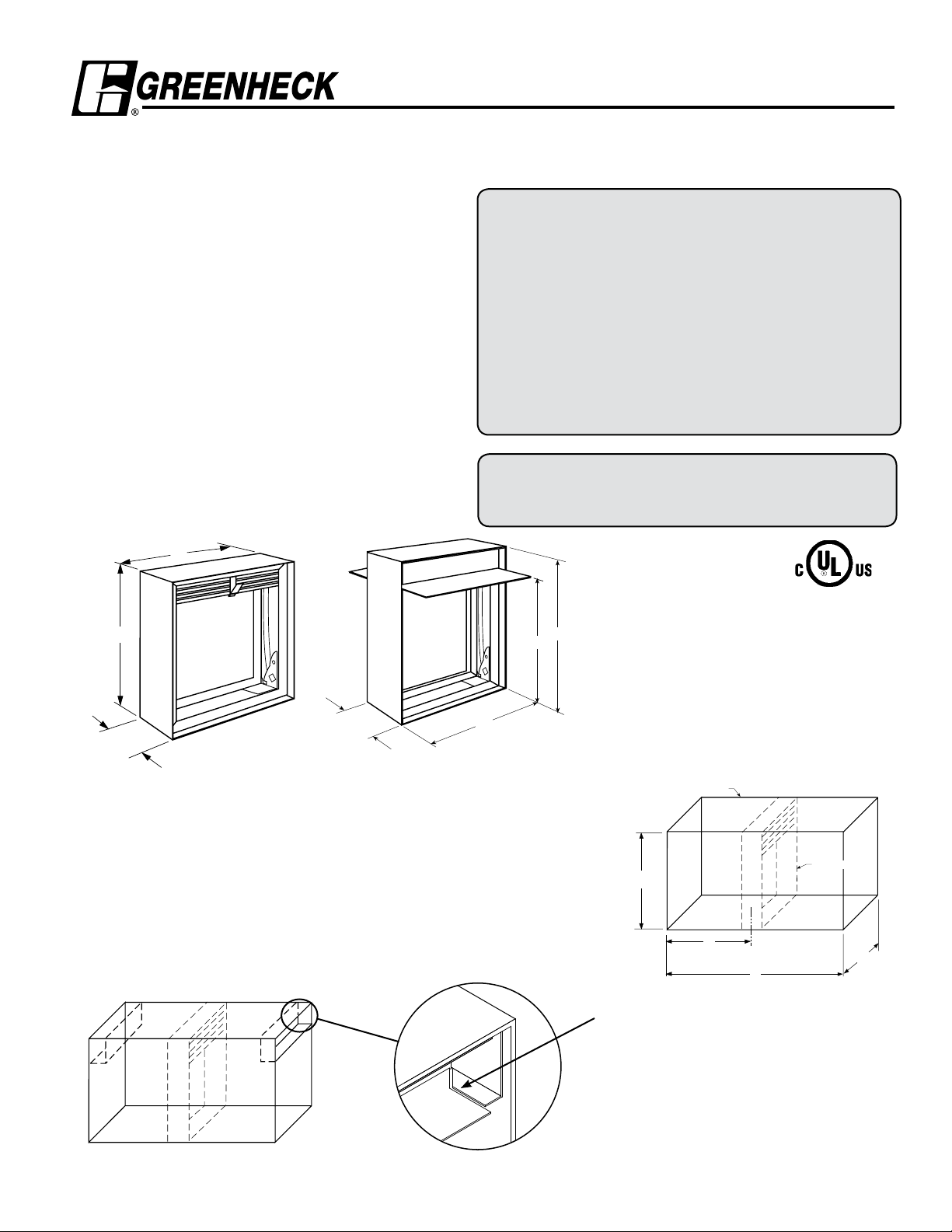
FACTORY SLEEVE OPTION
DFD-350 Fire Dampers are available in factory furnished sleeves. Sleeves are
galvanized steel and are available in 1.0mm - 1.5mm thicknesses and lengths up to
914mm.
“K” dimension specifies location of damper within the sleeve. Minimum is 102mm,
maximum is “L” less 102mm, which allows for mounting angle installation and
duct connection at each end of sleeve. If “K” dimension is not specified, it will be
provided as one half of “L” dimension (damper centered in sleeve).
Features:
• Stainless steel closure springs
• Fusible links (69° C for BS476, 74°C standard
for UL, 100°C available)
• Can be mounted horizontally or vertically.
These dimensions are furnished approximately 6mm undersize.
*
When sealed option is selected, B transitions
will need to be field sealed in the area where
duct to sleeve connection is made.
Type B with sleeve
Type B corner profile
Page 2
H*
P
W*
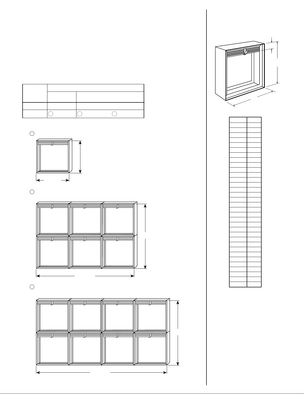
DFD-M150 Type A
914mm max.
914mm max.
2438mm max.
1219mm max.
3048mm max.
1016mm max.
Mult-Section Limitations
Maximum damper height is 1016mm when combination width is
greater than 2438mm and less than or equal to 3048mm.
3
Multi-Section Limitations
Maximum damper height is 1219mm when combination width is 2438mm or less.
2
Maximum Single Section Dimensions
1
SIZING AND ASSEMBLY DATA
Dampers larger than maximum single section size are supplied in 2 or more sections
of equal size. If ordered with a factory sleeve, multi-section dampers are factory
assembled ready for installation. If ordered without a factory sleeve, multi-section
dampers require field assembly. (See Greenheck Fire Damper Installation Instructions
#452763)
The following chart and illustrations show minimum and maximum damper section
size and assembly configurations for multi-section dampers.
SIZE LIMITATIONS
Vertical or Horizontal
Single Multi mm Section Section
Minimum 102 x 102 NA
Maximum 914 x 914 2438 x 1219
Installation of sizes larger than the maximums shown requires
approval of the authority having jurisdiction.
1 2 3
or 3048 x 1016
Blade Stack
Dimensions
H* P
102 20
127 20
152 23
178 28
203 30
229 33
254 33
279 36
305 41
330 43
356 46
381 46
406 51
432 53
457 56
483 58
508 61
533 66
559 66
584 69
610 74
635 79
660 81
686 81
711 84
737 86
762 91
787 94
813 94
838 99
864 99
889 104
914 107
These dimensions are furnished
*
approximately 6mm undersize.
(Dimension in mm)
Page 3

DFD-M150 Type B
Multi Section Limitations
Maximum damper height is 940mm when combination width is
greater than 2438mm and less than or equal to 3048mm.
3
Multi Section Limitations
Maximum damper height is 1143mm when combination width is 2438mm or less.
2
Maximum Single Section
Dimensions
1
2438mm
Max.
1143mm
Max.
3048mm
Max.
940mm
Max.
813mm
Max.
914mm
Max.
H*
O*
W*
76mm min.
1829mm max.
SIZING AND ASSEMBLY DATA
Dampers larger than maximum single section size are supplied in 2 or more sections of
equal size. If ordered with a factory sleeve, multi-section dampers are factory assembled
ready for installation. If ordered without a factory sleeve, multi-section dampers require field
assembly. (See Greenheck Fire Damper Installation Instructions #452763)
The following chart and illustrations show minimum and maximum damper section size and
assembly configurations for multi-section dampers.
SIZE LIMITATIONS
Vertical or Horizontal
Single Multi mm Section Section
Minimum 102 x 102 NA
Maximum 914 x 813 1219 x 813
Installation of sizes larger than the maximums shown requires
approval of the authority having jurisdiction.
DFD-M150 Type R
Sizing and Assembly Data
Dampers larger than maximum single section size are supplied as a
factory assembly of two or more sections of equal size.
Transition is centered on damper frame (or frame assembly for
multiple section dampers).
SIZE LIMITATIONS
Vertical or Horizontal Vertical Only
Minimum 76mm dia. NA
Maximum 1168mm dia. 1829mm dia.
Overall Damper
Dimensions
H* O*
76 127
102 152
127 178
152 203
178 229
203 254
229 279
254 305
279 330
305 356
330 381
356 406
381 457
406 483
432 508
457 533
483 559
508 584
533 610
559 660
584 686
610 711
635 737
660 762
686 787
711 813
737 838
762 864
787 889
813 914
These dimensions are furnished
*
approximately 6mm undersize.
(Dimension in mm)
Copyright © 2006 Greenheck Fan Corporation
DFD-M150 Rev. 4 December 2006
 Loading...