

Page 1
®
PN 457691
Models CW/CWB
Centrifugal Sidewall Exhaust Fans
Installation, Operation and Maintenance Manual
Please read and save these instructions for future reference. Read carefully before attempting to assemble,
install, operate or maintain the product described. Protect yourself and others by observing all safety
information. Failure to comply with instructions could result in personal injury and/or property damage!
Model CW
Direct Drive
Model CW is a direct drive
centrifugal sidewall exhaust fan.
These fans are specically designed
for wall mounted application.
Performance capabilities range up to
6,400 cfm (10,874 m3/hr) and up to
3 in. wg (747 Pa) of static pressure.
The maximum continuous operating
temperature for fan sizes 098-200 is 400°F (204°C)
and for fan sizes 060-095 is 160°F (71°C). CW fans
are available in fourteen sizes with nominal wheel
diameter ranging from 9 to 20 inches (229 mm to
508 mm) (060 - 200 unit sizes). Each fan shall bear
a permanently afxed manufacturer’s engraved
metal nameplate containing the model number and
individual serial number.
General Safety Information
Model CWB
Belt Drive
Model CWB is a belt drive centrifugal
sidewall exhaust fan. These fans are
specically designed for wall mounted
application. Performance capabilities
range up to 12,500 cfm (21,200 m3/hr)
and up to 2.75 in. wg (685 Pa) of static
pressure. The maximum continuous
operating temperature is 400°F (204.4°C).
CWB fans are available in nineteen sizes with nominal
wheel diameter ranging from 9 to 30 inches (229 to
762 mm) (098 - 300 unit sizes). Each fan shall bear
a permanently afxed manufacturer’s engraved
metal nameplate containing the model number and
individual serial number.
Only qualied personnel should install this fan.
Personnel should have a clear understanding of these
instructions and should be aware of general safety
precautions. Improper installation can result in electric
shock, possible injury due to coming in contact with
moving parts, as well as other potential hazards. Other
considerations may be required if high winds or seismic
activity are present. If more information is needed,
contact a licensed professional engineer before moving
forward.
DANGER
Always disconnect, lock and tag power source before
installing or servicing. Failure to disconnect power source
can result in re, shock or serious injury.
CAUTION
When servicing the fan, motor may be hot enough to
cause pain or injury. Allow motor to cool before servicing.
CAUTION
Precaution should be taken in explosive atmospheres.
1. Follow all local electrical and safety codes, as
well as the National Electrical Code (NEC) and the
National Fire Protection Agency (NFPA), where
applicable. Follow the Canadian Electric Code (CEC)
in Canada.
2. The rotation of the wheel is critical. It must be free
to rotate without striking or rubbing any stationary
objects.
3. Motor must be securely and adequately grounded.
4. Do not spin fan wheel faster than max cataloged fan
RPM. Adjustments to fan speed signicantly effects
motor load. If the fan RPM is changed, the motor
current should be checked to make sure it is not
exceeding the motor nameplate amps.
5. Do not allow the power cable to kink or come in
contact with oil, grease, hot surfaces, or chemicals.
Replace cord immediately if damaged.
6. Verify that the power source is compatible with the
equipment.
7. Never open access doors to a duct while the fan is
running.
Model CW/CWB • Centrifugal Sidewall Exhaust Fans
1
Page 2
®
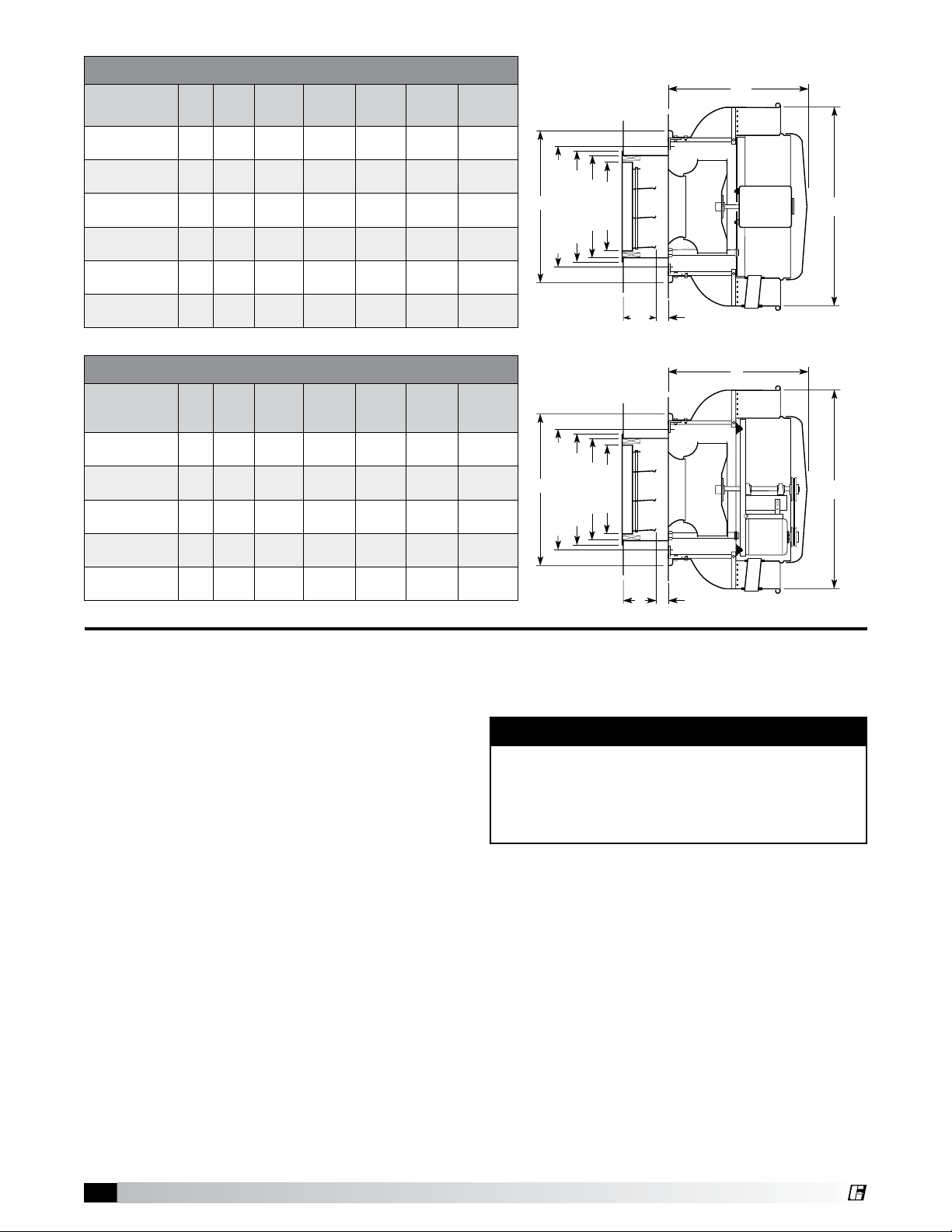
Mounting Hole Bolt Circle
C
*
A
B**
Damper Size
Wall Opening
Damper Frame Size
5"
C
*
5"
A
B
Wall Opening
Damper Frame Size
Damper Size
Mounting Hole Bolt Circle
CW - Direct Drive Dimensions
Wall
Model A B** C
3
⁄8
CW-060, 065,
070, 075
CW-080, 085,
090
CW-095
CW-098, 101,
121, 131
CW-141, 161
CW-180, 200
All dimensions in inches (millimeters). *NOTE: 2 inches minimum, 8 inches when motorized
option is required. *May vary depending on motor size.
18
(467)
21
(533)
21
(533)
247⁄8
(632)
7
28
(733)
3
35
(905)
131⁄2
(343)
133⁄8
(340)
151⁄4
(387)
281⁄4
(718)
⁄8
293⁄4
(756)
⁄8
285⁄8
(727)
Opening
143⁄4
(375)
177⁄8
(454)
177⁄8
(454)
193⁄4
(502)
221⁄8
(562)
273⁄4
(705)
Damper
81⁄2
(216)8 (203)
101⁄2
(267)
101⁄2
(267)
121⁄2
(318)
151⁄2
(394)
171⁄2
(445)
Size
10
(254)
10
(254)
12
(305)
15
(381)
17
(432)
Damper
Frame
10 (254)
Size
12
(305)
12
(305)
14
(356)
17
(432)
19
(483)
Mounting
Bolt
Circle
113⁄4
(298)
15
(381)
15
(381)
167⁄8
(429)
193⁄8
(492)
25
(635)
CWB - Belt Drive Dimensions
Wall
Model A B** C
7
⁄8
CWB-098, 101,
121, 131
CWB-141, 161
CWB-180, 200
CWB-220, 240
CWB-300
All dimensions in inches (millimeters). *NOTE: 2 inches minimum, 7 inches when motorized
option is required. **May vary depending on motor size.
24
(632)
28
(733)
35
(899)
25
42
(1087)
50
(1270)
281⁄4
(718)
7
⁄8
293⁄4
(756)
3
⁄8
285⁄8
(727)
⁄32
337⁄8
(860)
36
(914)
Opening
193⁄4
(502)
221⁄8
(562)
273⁄4
(705)
311⁄4
(794)
383⁄8
(975)
Damper
121⁄2
(318)
151⁄2
(394)
171⁄2
(445)
201⁄2
(521)
251⁄2
(648)
Size
12
(305)
15
(381)
17
(432)
20
(508)
25
(635)
Damper
Frame
Size
14
(356)
17
(432)
19
(483)
22
(559)
27
(686)
Mounting
Bolt
Circle
167⁄8
(429)
193⁄8
(492)
25
(635)
283⁄8
(721)
3527⁄32
(910)
Receiving
Upon receiving the product, check to make sure all
items are accounted for by referencing the bill of lading
to ensure all items were received. Inspect each crate for
shipping damage before accepting delivery. Notify the
carrier if any damage is noticed. The carrier will make
notication on the delivery receipt acknowledging any
damage to the product. All damage should be noted on
all the copies of the bill of lading which is countersigned
by the delivering carrier. A Carrier Inspection Report
should be lled out by the carrier upon arrival and
reported to the Trafc Department. If damaged upon
arrival, le a claim with carrier. Any physical damage
to the unit after acceptance is not the responsibility of
Greenheck Fan Corporation.
Unpacking
Verify that all required parts and the correct quantity
of each item have been received. If any items are
missing, report shortages to your local representative to
arrange for obtaining missing parts. Sometimes it is not
possible that all items for the unit be shipped together
due to availability of transportation and truck space.
Conrmation of shipment(s) must be limited to only
items on the bill of lading.
Handling
The motor amperage and voltage ratings must be
checked for compatibility to supply voltage prior to
nal electrical connection. For CW/CWB installations,
2
Model CW/CWB • Centrifugal Sidewall Exhaust Fans
the electrical supply should be routed through the
conduit chase located between the mounting plate and
the bottom of the motor compartment. Wiring must
conform to local and national codes.
CAUTION
Do not lift by the fan hood. Avoid lifting fans in a
way that will bend or distort fan parts. Never pass
slings or timbers through the venturi of fan. Fans
with special coatings or paints must be protected
in handling to prevent damage.
Storage
Fans are protected against damage during shipment. If
the unit cannot be installed and operated immediately,
precautions need to be taken to prevent deterioration of
the unit during storage. The user assumes responsibility
of the fan and accessories while in storage. Greenheck
Fan Corporation will not be responsible for damage
during storage. These suggestions are provided solely
as a convenience to the user.
Indoor
The ideal environment for the storage of fans and
accessories is indoors, above grade, in a low humidity
atmosphere which is sealed to prevent the entry of
blowing dust, rain or snow. Temperatures should be
evenly maintained between 30° to 110°F (-1° to 43°C)
Page 3
®
(wide temperature swings may cause condensation
1
2
3
1
2
and “sweating” of metal parts). All accessories must be
in a similar fashion until the fan equipment goes into
operation.
stored indoors in a clean, dry atmosphere.
Remove any accumulations of dirt, water, ice, or snow
and wipe dry before moving to indoor storage. To
avoid “sweating” of metal parts, allow cold parts to
reach room temperature. To dry parts and packages
use a portable electric heater to get rid of any moisture
buildup. Leave coverings loose to permit air circulation
and to allow for periodic inspection.
The unit should be stored at least 3½ in. (89 mm) off the
floor on wooden blocks covered with moisture proof
paper or polyethylene sheathing. Aisles between parts
and along all walls should be provided to permit air
circulation and space for inspection.
Installation
These fans exhaust directly away from the building,
therefore their location and placement should be
analyzed. Proximity to nearby buildings and people
must be considered.
Access to the motor compartment is accomplished by
removing the screws from the cover. The cover can
then be removed and placed on a flat surface in an area
protected from strong winds.
The motor’s amperage and voltage rating must be
checked for compatibility to the supply voltage prior
to final electrical connection. For NFPA Restaurant
Applications, the electrical supply must enter the
Outdoor
Fans designed for outdoor applications may be stored
outdoors, if absolutely necessary. Roads or aisles for
portable cranes and hauling equipment are needed.
The fan should be placed on a level surface to prevent
water from leaking into the fan. The fan should be
elevated on an adequate number of wooden blocks so
that it is above water and snow levels and has enough
blocking to prevent it from settling into soft ground.
Locate parts far enough apart to permit air circulation,
sunlight and space for periodic inspection. To minimize
water accumulation, place all fan parts on blocking
supports so that rain water will run off.
Do not cover parts with plastic lm or tarps as these
motor compartment through the breather tube. For
other non-flammable applications the electrical supply
can be routed through the conduit chase between
the mounting plate and the bottom of the motor
compartment. Consult local code authorities for your
specific requrements. UL/cUL 762 Installations are for
Restaurant Applications.
All CWB fans and CW fans with A, B and C motor RPMs
are the only fans approved for this installation. All must
include the suffix “G”.
All fans must be installed per NFPA 96 and meet all
local code requirements. In addition, the maximum
operating temperature at the fan must not exceed
375°F (191°C).
cause condensation of moisture from the air passing
through heating and cooling cycles.
Fan wheels should be blocked to prevent spinning
caused by strong winds.
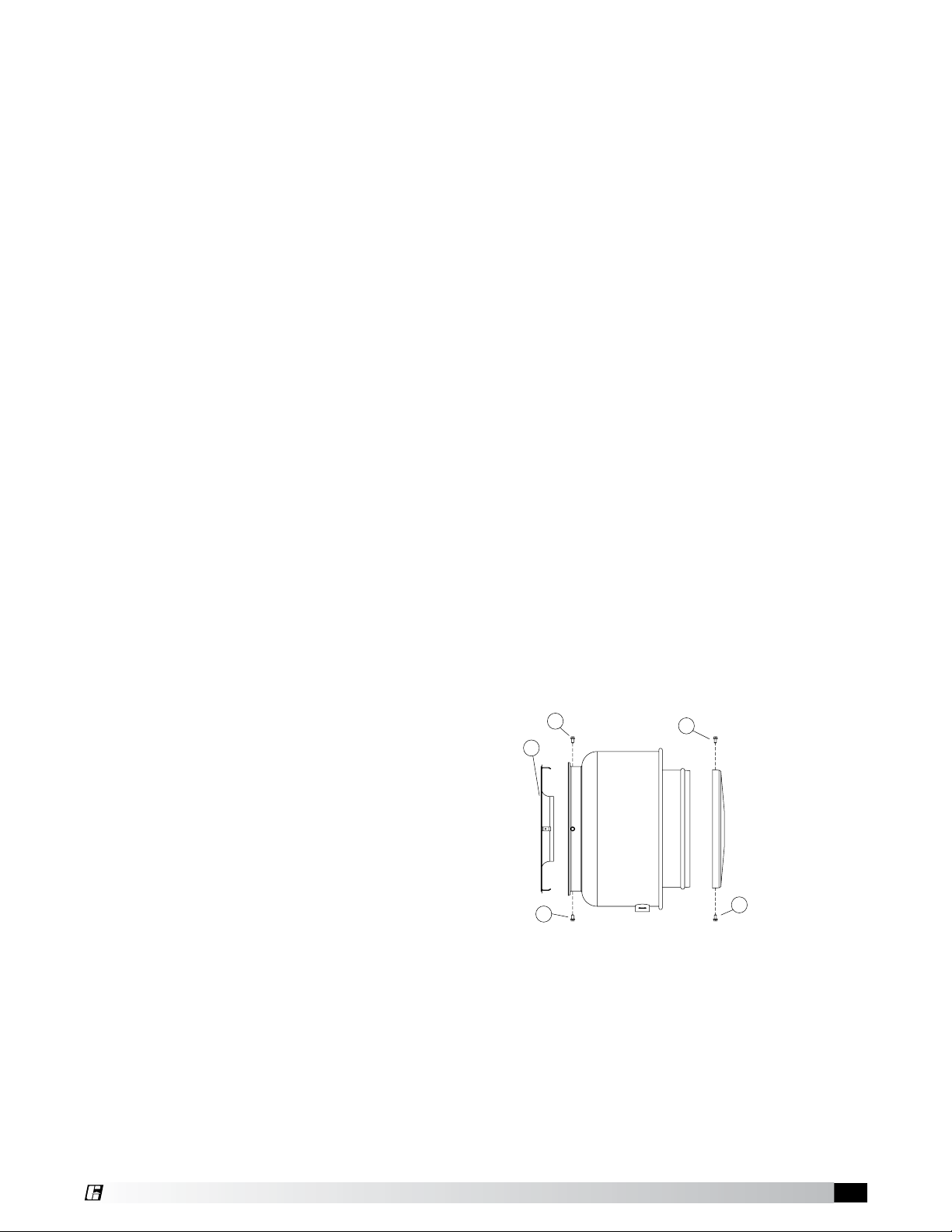
Typical Wall Mounting Installation
1. Remove mounting plate from unit by removing the
fasteners shown above marked by (1). Remove
motor compartment cover by removing fasteners
Inspection and Maintenance During
marked by (2).
Storage
While in storage, inspect fans once per month. Keep a
record of inspection and maintenance performed.
If moisture or dirt accumulations are found on parts,
the source should be located and eliminated. At each
inspection, rotate the wheel by hand ten to fteen
revolutions to distribute lubricant on motor. If paint
deterioration begins, consideration should be given to
touch-up or repainting. Fans with special coatings may
require special techniques for touch-up or repair.
Machined parts coated with rust preventive should be
restored to good condition promptly if signs of rust
occur. Immediately remove the original rust preventive
coating with petroleum solvent and clean with lint-free
cloths. Polish any remaining rust from surface with
crocus cloth or ne emery paper and oil. Do not destroy
the continuity of the surfaces. Thoroughly wipe clean
with Tectyl® 506 (Ashland Inc.) or the equivalent. For
hard to reach internal surfaces or for occasional use,
consider using Tectyl® 511M Rust Preventive, WD-40
or the equivalent.
Removing From Storage
As fans are removed from storage to be installed in their
nal location, they should be protected and maintained
2. Locate the mounting plate (3) at the desired position
and check to avoid unit clearance problems. Cut the
wall opening (4) as shown based upon dimensions
obtained from the Dimensional Data Section. Locate
top of mounting plate (decal) and attach to the wall
construction. The fasteners must pass through the
holes provided in the mounting angle clips (5) on the
®
mounting plate (3). For uneven surfaces, shims may
be required. Sealant or caulking should be applied in
the groove (6) formed by the mounting plate and the
wall to prevent moisture leakage into the building.
Model CW/CWB • Centrifugal Sidewall Exhaust Fans
3
Page 4

®
G
H
Clockwise
Airflow
Counterclockwise
Airflow
DETAIL
DETAIL
DECAL
TOP
Caulking
6
3
5
6
4
9
8
9
7
ELECTRICAL
WIRING
10
11
12
13
13
3. Once the mounting plate has been attached to the
wall, the unit can be installed. The unit should be
aligned with the breather tube (7) pointing down.
The electrical chase should be guided through the
hole in the motor compartment. The horizontal
support channels (8) should slide over the mounting
angle clips (10) on the mounting plate until the holes
in the windband and clips are aligned. Replace
fasteners (9) and tighten. Wiring now can be done.
Consult local code authorities for your specific
requirements.
4. During shipping, wheel position may shift.
Alignment should be as shown above (centered in
the inlet) and can be accomplished by loosening the
fasteners (11) located in the motor compartment.
For belt drive units, additional vertical alignment can
be accomplished by loosening the four fasteners on
the drive frame support angles, and the 2 fasteners
that hold the L-brackets to the support angles on
top (13). Also, horizontal alignment can be made by
loosening the bearings from the bearing plate.
Removal of the entire power pack (motor, drives
and wheel) for maintenance or cleaning can be
accomplished by removing the breather tube (12) and
fasteners (11).
CW/CWB Models 098 - 300
CW Models 060-095
Pre-Starting Checks
1. Check all fasteners and setscrews for tightness.
The wheel should rotate freely and be aligned as
shown in gure 7.
2. Wheel position is preset and the unit is test run at
the factory. Movement may occur during shipment
and realignment may be necessary.
Wheel Overlap and Gap Dimensions
Model G - Overlap in (mm) H - Gap in (mm)
060-095 – 3/32
098-161 1/4 (6) –
180-300 1/2
Figure 7
(13) –
3. Only CW unit - Centering height alignment can
be accomplished by loosening the set screws in
the wheel and moving the wheel to the desired
position.
4. Only CWB unit - Centering can be accomplished by
loosening the bolts holding the drive frame to the
shock mounts and repositioning the drive frame.
5. Only CWB unit - Wheel and inlet cone overlap
can be adjusted by loosening the setscrews in
the wheel and moving the wheel to the desired
position.
6. Only CWB unit - Fan RPM should be checked and
veried with a tachometer.
7. Check wheel rotation (viewing from the shaft
side) by momentarily energizing the unit. Rotation
should be clockwise and correspond to the rotation
decal on the unit, see gure 8. If wheel rotation is
incorrect reverse two of the wiring leads or check
motor wiring for single phase.
Wheel Rotation
All CW and CWB models
have clockwise rotation
when viewed from top
of fan
Figure 8
(2)
4
Model CW/CWB • Centrifugal Sidewall Exhaust Fans
Page 5

®
WARNING
Do not force belt(s). Forcing the
belt(s) will break the cords and
cause belt failure
Slack
Side
Correct direction of wheel rotation is critical.
Reversed rotation will result in poor air
performance, motor overloading and possible
burnout.
Model CWB
Pre-Starting Belt Tension Checks
8. Always loosen tension enough to install belts
without stretching, see gure 9.
Belts
Figure 9
WARNING
The fan has been checked for mechanical noises at
the factory prior to shipment. If mechanical noise
should develop, suggested corrective actions are
offered in the Troubleshooting section.
IMPORTANT
Over tightening will cause excessive bearing wear
and noise. Too little tension will cause slippage at
startup and uneven wear.
should have 15/64 in. (0.234 mm) (or about 1/4 in.
(6 mm)) of deection with moderate thumb pressure
at mid-point between pulleys (see gure 12b).
Deflection
9. For units with two groove pulleys, adjust so the
tension is equal in both belts.
10. If adjustments are made, it is very important to
check the pulleys for proper alignment. Misaligned
pulleys lead to excessive belt wear vibration, noise
and power loss, see gure 10.
Figure 10
11. For CWB units: Belt tension can be adjusted by
loosening four fasteners on the drive frame, see
gure 11. The motor plate slides on the slotted
adjusting arms and drive frame angles in the same
manner.
Fasteners
(4) *Fasteners
*Identical fasteners on
opposing side must also
be loosened.
Figure 12a Figure 12b
13. The adjustable motor pulley is factory set for the
RPM specied. Speed can be increased by closing
or decreased by opening the adjustable motor
pulley. Two groove variable pitch pulleys must be
adjusted an equal number of turns open or closed.
14. Any increase in speed represents a substantial
increase in the horsepower required by the unit.
15. Motor amperage should always be checked to avoid
serious damage to the motor when speed is varied.
Operation: CW/CWB
1. Before starting up or operating fan, check all
fasteners for tightness. In particular, check the
setscrews in wheel hub (and pulleys, if applicable).
2. While in the OFF position or before connecting the
fan to power, turn the fan wheel by hand to be sure
it is not striking the venturi or any obstacle.
3. Start the fan and shut it off immediately to check
rotation of the wheel with directional arrow in the
motor compartment, see gure 8.
4. When the fan is started, observe the operation and
check for any unusual noises.
5. With the system in full operation and all ductwork
attached, measure current input to the motor and
compare with the nameplate rating to determine if
the motor is operating under safe load conditions.
6. Keep inlets and approaches to fan clean and free
from obstruction.
Figure 11
12a. Sizes 071-161: Belts should be tensioned just
enough to prevent slippage at full load. Belts
should have a slight bow on the slack side while
running at full load (see gure 12a).
12b. Sizes 180-540: Belt tension should be adjusted to
allow 1/64 in. (0.397 mm) of deection per inch of
belt span. For example, a 15 in. (381 mm) belt span
Model CW/CWB • Centrifugal Sidewall Exhaust Fans
5
Page 6

®
Inspection: CW/CWB
Inspection of the fan should be conducted at the
rst 30 minute and 24 hour intervals of satisfactory
operation.
30 Minute Interval
Inspect bolts, setscrews and motor mounting bolts.
Adjust and tighten as necessary.
24 Hour Interval
Check all internal components. On CWB unit only,
inspect belt alignment and tension. Adjust and tighten
as necessary.
IMPORTANT
Adjust (tighten) belt tension after the rst 24-48 hours
of operation.
Maintenance: CW/CWB
A proper maintenance program will help these units
deliver years of dependable service. Installation and
maintenance are to be performed only by qualied
personnel who are familiar with local codes and
regulations and who are experienced with this type of
equipment.
Motor maintenance is generally limited to cleaning
and lubrication (where applicable). Cleaning should be
limited to exterior surfaces only. Removing dust buildup
on motor housing ensures proper motor cooling.
Greasing of motors is only intended when ttings are
provided. Many fractional horsepower motors are
permanently lubricated and should not be lubricated
after installation. Motors supplied with grease ttings
should be greased in accordance with manufacturers’
recommendations. Where motor temperatures do not
exceed 104ºF (40ºC), the grease should be replaced
after 2,000 hours of running time as a general rule.
Wheels require very little attention when moving
clean air. Occasionally, oil and dust may accumulate
causing imbalance. When this occurs the wheel and
housing should be cleaned to ensure smooth and safe
operation.
All fasteners should be checked for tightness each time
maintenance checks are performed prior to restarting
unit.
A proper maintenance program will help these units
deliver years of dependable service.
Belt/Bearing Maintenance CWB Unit
1. Belts tend to stretch after a period of time. They
should be checked periodically for wear and
tightness. When replacing belts, use the same type
as supplied with the unit.
2. Matched belts should always be used on units with
multi-groove pulleys.
3. For belt replacement, loosen the tensioning device
enough to allow removal of the belt by hand. Do not
force the belts on or off. This may cause cords to
break, leading to premature failure.
WARNING
Always disconnect, lock and tag power source before
servicing. Failure to disconnect power source can
result in re, shock or serious injury.
CAUTION
Uneven cleaning of the wheel will produce an out of
balance condition that will cause vibration in the fan.
WARNING
This unit should be made non-functional when
cleaning the wheel or housing (fuses removed,
disconnect locked off).
4. Once installed, adjust belts as shown in
“Pre-Starting Checks.”
5. Shaft bearings can be classied in two
groups:relubricating and non-relubricating. All
non-relubricating bearings on standard model
CWB fans are factory lubricated and require no
further lubrication under normal use (between
-20º to 180ºF (-29º to 82ºC) in a relatively clean
environment).
6. Units installed in hot, humid or dirty locations
should be equipped with special bearings. These
bearings will require frequent lubrication. On CWB
belt driven fans, the standard cast pillow block
bearings are factory lubricated and are provided
with external grease ttings. Annual lubrication
is recommended, or more frequently if needed,
see Table 2. Do not over-grease. Use only one or
two shots of lubricant with a hand gun. Maximum
hand gun rating is 40 psi. Rotate bearings during
lubrication where good safety practice permits.
Caution should be employed to prevent over
packing or contamination.
7. Grease ttings should be wiped clean. The unit
should be in operation while lubricating. Extreme
care should be used around moving parts.
8. Grease should be pumped in very slowly until a
slight bead forms around the seal. A high grade
lithium base grease should be used.
9. When installing restaurant exhaust applications
follow NFPA 70 for cleaning fans.
10. Grease containers must be emptied at regular
intervals to prevent overow.
11. To ensure tightness, check pulley setscrews. Proper
keys must be in keyways.
12. Fan RPM should not be readjusted. Only use
pulleys of identical size and type when replacing
pulleys.
13. During the rst few months of operation check
bearing set screws periodically to ensure tightness.
14. If unit is to be left idle for an extended period,
remove belts and store in a cool, dry place to avoid
premature belt failure.
6
Model CW/CWB • Centrifugal Sidewall Exhaust Fans
Page 7

®
Recommended Relubrication
Frequency in Months
NOTE: If unusual environment conditions exist
(extreme temperature, moisture or contaminants) more
frequent lubrication is required.
A good quality lithium base grease, conforming to
NLGI Grade 2 consistency, such as those listed here
may be used.
Table 2: Suggested Fan Bearing Greasing Intervals
Interval
(months)
1 to 3
3 to 6
6 to 12
12 to 18
Heavy duty in dirty, dusty locations; high ambient
temperatures; moisture laden atmosphere;
vibration.
12 to 24 hours per day, heavy duty, or if moisture
is present
8 to 16 hours per day in clean, relatively dry
atmosphere
Infrequent operation or light duty in clean
atmosphere
Type of Service
Table 3: Grease Manufacturers
Manufacturer Grease (NLGI #2)
U.S. Electric Motors Grease No. 83343
Chevron U.S.A. Inc Chevron SRI Grease #2
Mobil Oil Corporation
Texaco, Inc.
Amoco Oil Co. Rykon Premium #2
Exxon Unirex N2
Shell B Shell Alvania #2
Mobilith
Mobil 532
Premium BRB #2
Texaco Multifak #2
Parts List
NOTE
Each fan bears a manufacturer’s nameplate with model number and serial number embossed. This information will assist the local Greenheck representative and the factory in providing service and replacement parts. Before taking any
corrective action, make certain unit is not capable of operation during repairs.
CAUTION
A fan manufactured with an explosion resistant motor does not certify the entire unit to be explosion proof.
CW Direct Drive Centrifugal Sidewall Exhaust Fan
Windband
Mounting Plate
Wheel
Breather Tube
Birdscreen
Motor Compartment
Cover
Model CW/CWB • Centrifugal Sidewall Exhaust Fans
7
Page 8

®
Mounting Plate
CWB Belt Drive Centrifugal Sidewall Exhaust Fan
Windband
Birdscreen
Motor Compartment
Breather Tube
Wheel Cover
Troubleshooting
WARNING: Before taking any corrective action, make certain unit is not capable of operation during repairs.
PROBLEM CAUSE CORRECTIVE ACTION
Bad Bearings Replace.
Clean and remove all dirt buildup off wheel. Check wheel
balance, rebalance in place if necessary.
Center wheel on inlet, see gure 7.
Remove objects, check for damage or unbalance.
Check system: Proper operation of backdraft or control
dampers, obstruction in ductwork, clean dirty lters.
Excessive Noise
or Vibration
Reduced airow
Wheel unbalance
Belts too tight or too loose Adjust tension, see gure 12a-b.
Wheel improperly aligned and
rubbing
Loose drive or motor pulleys Align and tighten. See “Pre-Starting Checks”, see page 4-6.
Foreign objects in wheel or
housing
System resistance too high
Unit running backwards Correct as shown in gure 8.
Excessive dirt buildup on wheels Clean wheel.
Improper wheel alignment Center wheel on inlets, see Pre-Starting checks and gure 7.
Warranty
Greenheck warrants this equipment to be free from defects in material and workmanship for a period of
one year from the purchase date. Any units or parts which prove defective during the warranty period will
be replaced at our option when returned to our factory, transportation prepaid. Motors are warranted by the
motor manufacturer for a period of one year. Should motors furnished by Greenheck prove defective during
this period, they should be returned to the nearest authorized motor service station. Greenheck will not be
responsible for any removal or installation costs.
As a result of our commitment to continuous improvement, Greenheck reserves the right to change specifications
without notice.
Greenheck Catalog Series C provides additional information describing the
equipment, fan performance, available accessories, and specication data.
AMCA Publication 410-96, Safety Practices for Users and Installers of Industrial
and Commercial Fans, provides additional safety information. This publication
can be obtained from AMCA International, Inc. at: www.amca.org.
Phone: (715) 359-6171 • Fax: (715) 355-2399 • E-mail: gfcinfo@greenheck.com • Website: www.greenheck.com
8 457691 • Models CW/CWB, Rev. 5, September 2008 Copyright 2008 © Greenheck Fan Corp
 Loading...