

Page 1
Part Number 474754
®
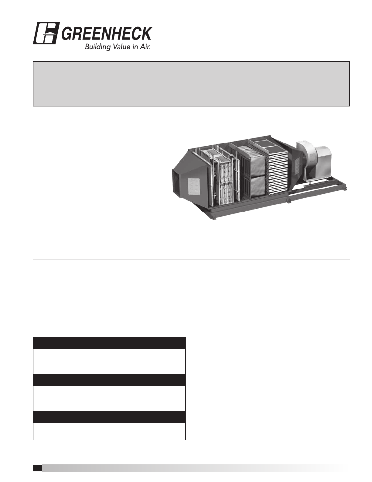
Grease Grabber™ Power Play
Kitchen Exhaust Pollution Control System
Installation, Operation and Maintenance Manual
Please read and save these instructions. Read carefully before attempting to assemble, install, operate or maintain the
product described. Protect yourself and others by observing all safety information. Failure to comply with instructions
could result in personal injury and/or property damage! Retain instructions for future reference.
Grease Grabber™ Power Play
The Greenheck Grease Grabber™ Power Play
is a pre-engineered electrostatic precipitator
type filtration pollution control unit with
integral exhaust fan (available without exhaust
fan as an option). The unit is designed to
remove grease and smoke particles as well
as odor molecules from the kitchen exhaust
airstream. This installation manual covers
procedures for receiving, installing, and
maintaining the filtered section of the unit.
For additional instructions and maintenance
information on the integral exhaust fan,
when applicable, refer to the fan nameplate
to determine model type and visit www.greenheck.com to
download the corresponding manual.
General Safety Information
Only qualified personnel should install this system.
Personnel should have a clear understanding of these
instructions and should be aware of general safety
precautions. Improper installation can result in electric
shock, possible injury due to coming in contact with
moving parts, as well as other potential hazards.
Other considerations may be required if high winds
or seismic activity are present. If more information
is needed, contact a licensed professional engineer
before moving forward.
DANGER
Always disconnect power before working on or near
this equipment. Lock and tag the disconnect switch
or breaker to prevent accidental power up.
CAUTION
When servicing the fan, motor may be hot enough
to cause pain or injury. Allow motor to cool before
servicing.
CAUTION
Do not install this equipment in explosive
atmospheres.
• Follow all local electrical and safety codes, as well
as the National Electrical Code (NEC), the National
Fire Protection Agency (NFPA), where applicable.
Follow the Canadian Electric Code (CEC) in
Canada.
• The rotation of the fan wheel is critical. It must
be free to rotate without striking or rubbing any
stationary objects.
• Fan motor must be securely and adequately
grounded.
• Do not spin fan wheel faster than maximum
cataloged fan rpm. Adjustments to fan speed
significantly effects motor load. If the fan RPM is
changed, the motor current should be checked to
make sure it is not exceeding the motor nameplate
amps.
• Do not allow the power cable to kink or come in
contact with oil, grease, hot surfaces or chemicals.
Replace cord immediately if damaged.
• Verify that the power source is compatible with the
equipment.
• Never open access doors to a duct while the fan is
running.
• The precipitator contains safety electrical interlock
switches at all maintenance access doors. Do not
attempt to defeat these interlocks.
Grease Grabber™ Power Play Kitchen Exhaust Pollution Control System
1
Page 2

Receiving
Upon receiving the product check to make sure all
items are accounted for by referencing the packing
list ensuring all items were received. Inspect each
crate for shipping damage before accepting delivery.
Notify the carrier if any damage is noticed. The
carrier will make notification on the delivery receipt
acknowledging any damage to the product. All
damage should be noted on all the copies of the bill
of lading which is countersigned by the delivering
carrier. A Carrier Inspection Report should be filled
out by the carrier upon arrival and filed with the
Traffic Department. If damaged upon arrival, file claim
with carrier. Any physical damage to the unit after
acceptance is not the responsibility of Greenheck Fan
Corporation.
Unpacking
Verify that all required parts and the correct quantity
of each item have been received. If any items are
missing, report shortages to your local representative
to arrange for obtaining missing parts. Sometimes it
is not possible that all items for the unit be shipped
together due to availability of transportation and truck
space. Confirmation of shipment(s) must be limited
to only items on the packing list. Filters and carbon
panels are shipped on separate skids in their original
packaging. Do not remove factory packaging or install
filters until just prior to commissioning. Remove all
other shipping/packing materials including fan tie
down straps.
Handling
Units are to be rigged and moved by the lifting
brackets provided or by the skid when a forklift is
used. Location of brackets varies by model and size.
Handle in such a manner as to keep from scratching
or chipping the coating. Damaged finish may reduce
ability of unit to resist corrosion.
Storage
Units are protected against damage during shipment. If
the unit cannot be installed and operated immediately,
precautions need to be taken to prevent deterioration
of the unit during storage. The user assumes
responsibility of the unit and accessories while in
storage. The manufacturer will not be responsible
for damage during storage. These suggestions are
provided solely as a convenience to the user.
INDOOR
The ideal environment for the storage of units and
accessories is indoors, above grade, in a low humidity
atmosphere which is sealed to prevent the entry of
blowing dust, rain, or snow. Temperatures should
be evenly maintained between 30°F (-1°C) and
110°F (43°C) (wide temperature swings may cause
condensation and “sweating” of metal parts). All
accessories must be stored indoors in a clean, dry
atmosphere.
Remove any accumulations of dirt, water, ice, or snow
and wipe dry before moving to indoor storage. To
Grease Grabber™ Power Play Kitchen Exhaust Pollution Control System
2
avoid “sweating” of metal parts allow cold parts to
reach room temperature. To dry parts and packages
use a portable electric heater to get rid of any
moisture build up. Leave coverings loose to permit air
circulation and to allow for periodic inspection.
OUTDOOR
Units designed for outdoor applications may be stored
outdoors, if absolutely necessary. Roads or aisles for
portable cranes and hauling equipment are needed.
The unit should be placed on a level surface to
prevent water from leaking into it. The unit should be
elevated on an adequate number of wooden blocks
so that it is above water and snow levels and has
enough blocking to prevent it from settling into soft
ground. Locate parts far enough apart to permit air
circulation, sunlight, and space for periodic inspection.
To minimize water accumulation, place all unit parts on
blocking supports so that rain water will run off.
Do not cover parts with plastic film or tarps as these
cause condensation of moisture from the air passing
through heating and cooling cycles.
Inspection and Maintenance during
Storage
While in storage, inspect equipment once per month.
Keep a record of inspection and maintenance
performed.
If moisture or dirt accumulations are found on parts,
the source should be located and eliminated. At each
inspection, rotate the fan wheel by hand ten to fifteen
revolutions to distribute lubricant on motor. Every three
months, the fan motor should be energized. If paint
deterioration begins, consideration should be given to
touch-up or repainting. Fans with special coatings may
require special techniques for touch-up or repair.
Machined parts coated with rust preventive should be
restored to good condition promptly if signs of rust
occur. Immediately remove the original rust preventive
coating with petroleum solvent and clean with lintfree cloths. Polish any remaining rust from surface
with crocus cloth or fine emery paper and oil. Do not
destroy the continuity of the surfaces. Wipe thoroughly
clean with Tectyl® 506 (Ashland Inc.) or the equivalent.
For hard to reach internal surfaces or for occasional
use, consider using Tectyl® 511M Rust Preventive or
WD-40® or the equivalent.
Removing from Storage
As units are removed from storage to be installed
in their final location, they should be protected and
maintained in a similar fashion, until the equipment
goes into operation. Prior to installing the unit and
system components, inspect the unit assembly to
make sure it is in working order.
1. Check all fasteners, set screws on the fan, wheel,
bearings, drive, motor base, and accessories for
tightness.
2. Rotate the fan wheel(s), where applicable, by hand
and assure no parts are rubbing.
Page 3
Table of Contents
Installation .................................4
Rigging/Placing Equipment .................4
Duct Connections .........................5
Plumbing ..................................5
Detergent Dispenser .......................5
Cabinet Assembly .........................5
Electrical ..................................6
Electrostatic Cell Wiring ....................6
Exhaust Fan Motor Wiring ..................7
System Control Panel Wiring ................7
Initial System Start-Up .......................7
Manual vs. Auto Operation ..................8
Operation ..................................8
Washing ..................................9
Reset Mode ...............................9
Detergent Dispenser .......................10
Adjustments ..............................10
Flow Control Valve Adjustment ...............10
Maintenance ..............................10
Maintenance Log ...........................12
Warranty ..................................12
An aluminum mesh pre-filter removes large airborne
particles from the incoming airstream prior to reaching
the ionizer cell. The permanent electrostatic collector
section removes grease and smoke particles from
the airstream using a high voltage ionizer cell(s). The
ionizer imparts a positive charge on the grease and
smoke particles as they pass. These particles are then
repelled by positively charged plates and collected
on negatively charged plates. Upon completion of
each cooking day, a wash sequence is initiated for the
self-cleaning function of the electrostatic cell via the
remote mounted control panel. The aluminum mesh
mist eliminator prevents wash water from entering
the safety filter and carbon panel sections of the unit.
The safety bag filter is intended to protect the carbon
panel section if power is lost to the ionizer collector
cell.
NOTE
Power Play is designed to remove sub-micron,
airborne particulate generated from cooking
processes. This system is NOT INTENDED to
eliminate regular hood and ductwork cleaning and
service. Improper care and maintenance of this
system and associated hoods and ductwork may
present a fire hazard.
Grease Grabber™ Power Play
System Function
Grease Grabber Power Play is an electrostatic
precipitator style air filtration unit, with an additional
carbon filter module, designed for two specific
functions:
• Remove smoke/grease particles from kitchen
exhaust.
• Remove odor molecules from kitchen exhaust.
NOTE
Grease Grabber Power Play must be connected to a
listed exhaust hood assembly and must be installed
in accordance with local building codes, NFPA 96
and NEC.
NOTE
The unit must be installed with a minimum 18 inch
clearance to combustible materials and must be
installed as part of a listed duct assembly.
System Components
NOTE
The installation criteria for each of the system
components shown below should be considered
when selecting a site for install. For further
detail on installing the components, refer to the
INSTALLATION section on page 4.
Cabinet Assembly
The unit body is shipped on a common mounting
rail ready for installation. If the unit was ordered with
an exhaust fan, the fan will also be mounted as part
of the cabinet assembly. Unless specified at time of
order, the cabinet assembly must be mounted indoors
and be protected from weather as well as be easily
accessible for service personnel. (1) 1½ or 2 inch
(depending on unit size) water supply line and (1)
3inch waste water drain line is required at the unit for
the system’s wash function.
Safety Filters & Carbon Panels
Filter and ionizer cell quantities for each stage are
based on unit size (see table on page 4). A consistent
quantity of filters/ionizer cells are provided for
each stage of the unit (pre-filter, ionizer cells, mist
eliminator, and safety bag filter). Quantity of carbon
panels will vary based upon unit exhaust rate. Install
filters and carbon panels only when system is ready
for start-up.
Grease Grabber™ Power Play Kitchen Exhaust Pollution Control System
3
Page 4
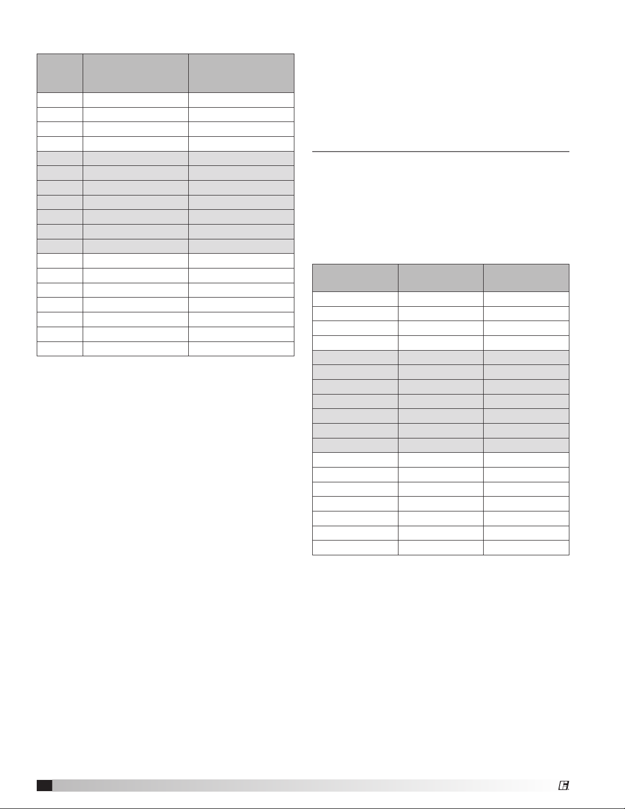
Filter Quantities
Unit
Size
02-03 1 1
02-04 2 0
02-05 2 1
02-06 3 0
04-03 2 2
04-04 4 0
04-05 4 2
04-06 6 0
04-07 6 2
04-08 8 0
04-09 8 2
06-03 3 3
06-04 6 0
06-05 6 3
06-06 9 0
06-07 9 3
06-08 12 0
06-09 12 3
Remote Mounted Detergent Dispenser
A 55 gallon remote mounted detergent dispenser
is included as part of the electrostatic collector
self-wash system. Included as part of the 55 gallon
dispenser assembly is a solenoid valve, pressure
gauge, ball valve, y strainer, and backflow preventer.
The detergent dispenser must be mounted indoors
on a solid, level foundation, as close to the cabinet
assembly as possible, and in a freeze protected
location accessible to maintenance personnel. The
1/2 inch line from the detergent dispenser must be
connected to the water supply line within 5 feet of
the precipitator. Refer to the PLUMBING section for
details on plumbing connections.
Remote Mounted System Control Panel and
Power Pack (2 pieces)
The system control panel allows the user to interface
with the unit and controls operation as well as
monitors wash and other functions. The Power
Pack contains a power transformer and works in
conjunction with the System Control Panel and the
unit’s high voltage ionizer cells. The System Control
Panel should be mounted in an area easily accessible
to daily operational staff. The Power Pack should be
mounted as close as possible to the System Control
Panel and both should be mounted as close to the
cabinet assembly as possible. Allow adequate room
from the face of the panels for door swing clearance
and servicing.
Safety Filter
Quantity
(2 ft. tall x 2 ft. wide)
Safety Filter
Quantity
(2 ft. tall x 1 ft. wide)
High Voltage Cable
High voltage cable is supplied to connect the ionizer/
collector sections of the precipitator to the ionizer and
collector terminals in the Power Pack. The red cable
(50 ft supplied) is used for the ionizer and the blue
cable (50 ft supplied) is used for the collector. Refer to
the ELECTRICAL section for details on wiring.
Installation
Rigging/Placing Equipment
1. The unit is furnished with lifting lugs at the four
corners and along the length as necessary.
2. Lift into place using all the lifting lugs.
3. Field weight will vary depending upon final
selections such as fan type, accessories, etc.
Approximate weights are shown in the table below.
Unit Size
02-03 3100 1409
02-04 3620 1645
02-05 4025 1830
02-06 4280 1945
04-03 4000 1818
04-04 4580 2082
04-05 5200 2364
04-06 5700 2591
04-07 6420 2918
04-08 7080 3218
04-09 7560 3436
06-03 5200 2364
06-04 6140 2791
06-05 6800 3091
06-06 7325 3330
06-07 8275 3761
06-08 8800 4000
06-09 9510 4350
4. The unit can be positioned on a base or curb
suitable for this purpose.
5. The unit must be anchored to its base/curb.
6. Alternatively, the unit may be suspended from
an adequate overhead structure, using suitable
undercarriage or hanging rods (by others). If the
unit is suspended by hanging rods, minimum
1/2inch (12.7 mm) diameter threaded rod is to be
used. All hanger brackets/lifting lugs must be used
to ensure proper support of the unit. The unit must
also be hung level to ensure proper operation.
7. A service clearance of 42 inches must be provided
on the access door side of the unit.
8. A minimum 18 inch clearance must be maintained
between this unit and any combustible material.
Approximate
Weight (lbs)
Approximate
Weight (kg)
Grease Grabber™ Power Play Kitchen Exhaust Pollution Control System
4
Page 5
9. The remote mounted detergent dispenser frame
mounts to a foundation using the four mounting
holes located at the base of the unit. For details on
wiring this item, refer to the ELECTRICAL section.
For details on plumbing connections, refer to the
PLUMBING section.
Duct Connections
Ductwork must conform to the IMC and SMACNA
guidelines.
As specified in NFPA 96, Ch. 7.5 (latest edition),
exhaust duct systems must be constructed in the
following manner; unless otherwise specified by the
local authority having jurisdiction (AHJ).
Materials
Ducts shall be constructed of and supported by
carbon steel not less than 1.37 mm (0.054 in.) (No. 16
MSG) in thickness or stainless steel not less than 1.09
mm (0.043 in.) (No. 18 MSG) in thickness.
Installation
All seams, joints, penetrations, and duct to hood collar
connections shall have a liquid-tight external weld.
An inlet transition is furnished to match the inlet duct
size. The inlet transition is furnished with a listed duct
access door for inspection and cleaning.
Units intended for indoor mounting are provided with
an outlet mounting flange, either at the unit discharge
or as part of a factory supplied UL 762 listed exhaust
fan. Outlet ductwork from the exhaust fan is required to
be per the above mentioned methods unless otherwise
specified by the local authority having jurisdiction
(AHJ).
NOTE
All water piping exposed to freezing temperatures
must to be trace heated and insulated to prevent
damage to the unit.
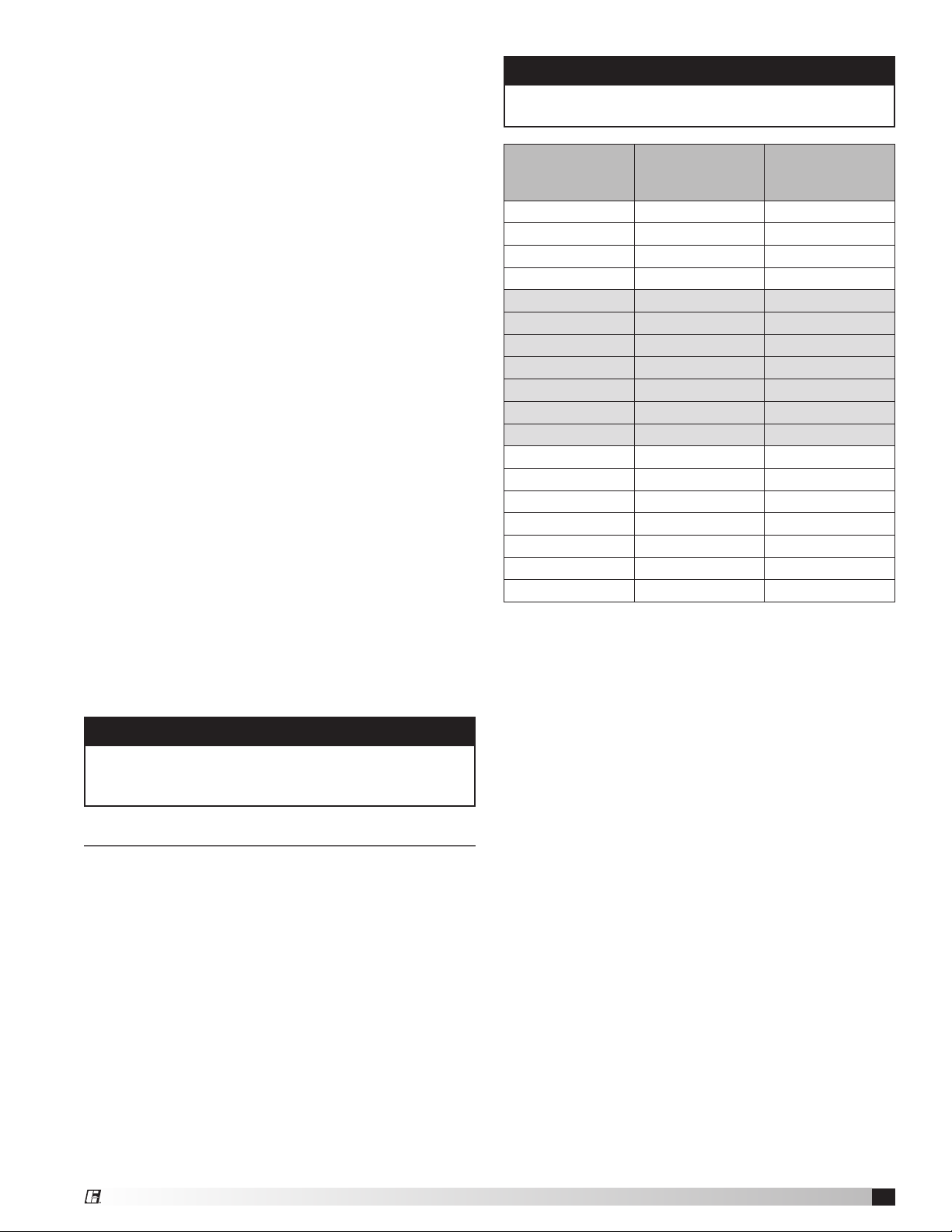
NOTE
For unit sizes 06-08 and 06-09, a minimum 2 inch
incoming water service is required.
Wash Cycle
Unit Size
02-03 7.2 .36
02-04 9.6 .48
02-05 12.0 .60
02-06 14.4 .72
04-03 14.4 .72
04-04 19.2 .96
04-05 24.0 1.20
04-06 28.8 1.44
04-07 33.6 1.68
04-08 38.4 1.92
04-09 43.2 2.16
06-03 21.6 1.08
06-04 28.8 1.44
06-05 36.0 1.80
06-06 43.2 2.16
06-07 50.4 2.52
06-08 57.6 2.88
06-09 64.8 3.24
Detergent Dispenser
From the pump located on the base of the detergent
dispenser, connect a ½-inch piping connection for the
detergent supply to the 1½-inch water supply line. A
quarter turn ball valve (by others) can be installed on
this line if necessary for servicing. The connection of
the ½-inch detergent supply line to the 1½-inch water
supply line should be made within 5 feet of the cabinet
assembly.
Water Flow
Rate (gpm)
Wash Cycle
Detergent Flow
Rate (gpm)
Plumbing
Once all system components are installed, plumbing
connections for the system can be made. It is
recommended that plumbing connections be done
prior to making electrical connections.
From the building, a 1½- or 2-inch (refer to drawings)
hot water line is required for connecting the wash
system. Recommended water temperature is 140˚F
at 45 psi pressure. Refer to the chart on this page
for information on water and detergent quantity
requirements. Install the quarter turn ball valve
(provided) at the incoming water source to allow the
water to be turned off for servicing. Next, install the
strainer (provided), backflow preventer (provided),
pressure gauge (provided), and solenoid valve
(provided) respectively. Locate these items along
the incoming water line in a location convenient for
inspection/servicing.
Grease Grabber™ Power Play Kitchen Exhaust Pollution Control System
Cabinet Assembly
The unit is supplied with two (2) 1¼- or (2) 1½-inch
wash headers located at the top of the cabinet
assembly. Connect the water supply line to both of the
wash headers at the top of the cabinet. Bring a 3-inch
waste water drain piping connection with P trap to the
drain pipe on the side of the cabinet assembly. The
trap drain line water column for the drain should be
sized for the total system resistance plus 1 in. wg.
5
Page 6

Electrical
Once all system components are installed plumbing
connections for the system can be made. It is
recommended that plumbing connections be done
prior to making electrical connections.
CAUTION
RISK OF ELECTRIC SHOCK. All wiring to be done
by qualified personnel only.
NOTE
All wiring must be done according to the equipment
data plate information, NEC (National Electrical Code
NFPA 70), and local codes.
NOTE
All wiring must be permanently installed in conduit.
Under no circumstances should extension cords be
used to connect the source of electrical supply to
the equipment.
NOTE
The system control panel, power pack, and cabinet
assembly housing to a structural steel or earth
ground. The detergent pump motor and solenoid
valve must also be appropriately grounded.
Electrostatic Cell Wiring
Using the supplied red high voltage cable in a
dedicated conduit line, connect the terminal point of
the ionizer portion of the cells to the Ionizer terminal in
the system power pack. Using the supplied blue high
voltage cable in a separate dedicated conduit line,
connect the terminal point of the collector portion of
the cells to the collector terminal in the system power
pack (See FIGURE 1).
Figure 1
Red high voltage cable
from Power Pack
Blue high voltage cable
from Power Pack
Knockout locations for conduit connections to carry
the high voltage cables are located at the top and
side of the system power pack and the sides of the
terminal box on top of the cabinet assembly. Use a
knockout punch to open holes for minimum 1/2-inch
conduit. Use caution to keep the system power pack
and terminal box interiors free of scraps and other
debris.
NOTE
50 feet of each the red and blue high voltage cable
are provided with the unit. Under no circumstances
should the high voltage cable be spliced or
terminated at locations other than the specified
terminal points. If longer lengths of high voltage
cable are required for installation, consult the
manufacturer.
Once conduit is in place and high voltage cable has
been run, terminate the high voltage cables at the
power pack by stripping approximately 3/8-inch
of insulation from each wire and attach a supplied
terminal ring to each. Securely attach the terminal
ring end of the red cable to the Ionizer terminal in
the power pack and the terminal ring end of the
blue cable to the collector terminal in the power
pack (See FIGURE 2). After the connections are
made, completely coat the terminal connection with
minimum 1/4-inch thick layer of silicone caulk (See
FIGURE 3).
Figure 2
Conduit with
bushing
Blue
Ring
terminal
AIR
FLOW
AIR
Airflow
FLOW
AIR
FLOW
NOTE
Do not connect the ends of the high voltage cable to
the terminal points until all conduits are installed and
the high voltage cable is run.
Grease Grabber™ Power Play Kitchen Exhaust Pollution Control System
6
Figure 3
Silicone
caulk
Collector
Ionizer
Cable must pass
through clamp
Red
Page 7

Terminate the other end of the high voltage cables
at the system cabinet on the unit housing. Ensure
enough cable is run to reach approximately 2 inches
past the high voltage spark plug terminal point on the
upper most electrostatic collector. Slide the silicone
boot over the end of the high voltage cable and strip
approximately 3/4 inch of insulation from the end of
the cable. Fold the exposed wire down and back over
the insulated end and tightly crimp on the supplied
terminal connection (See FIGURE 4). Slide the silicone
boot back over the terminal end of the cable and
firmly press onto the end of the high voltage spark
plug terminal point until the connection snaps into
place.
Figure 4
Strip 3/4 inch insulation
from cable
Fold wire down and back
Lay wire in terminal and
clamp tightly
Connect the power pack to the system control
panel using 14 gauge wire. Wire terminals 1, 2, and
3 in the power pack to terminals 1TB17, 2TB4, and
ground, respectively, in the system control panel. Wire
terminals 6, 7, 8, and 9 in the power pack to terminals
1TB16, 1TB18, 1TB15, and 1TB19, respectively, in the
system control panel.
Connect the junction box on top of the system cabinet
to the system control panel using 14 gauge wire.
Connect terminals 5TB1 and 5TB2 (access door safety
interlock) to terminals 1TB4 and 1TB13, respectively,
in the system control panel. Also connect terminals
5TB5, 5TB7 (upstream wash motor), 5TB8, and 5TB10
(downstream wash motor) to terminals 1TB21, 2TB18,
1TB22, and 2TB19, respectively, in the system control
panel.
NOTE
The system control panel is furnished with prewired circuits that can be interfaced/interlocked
with a make-up air unit, remote start/stop, remote
enunciator panel, fire suppression system, and/or
damper control. Please refer to the plumbing and
electrical schematics section for details on wiring
these components.
Slide silicone boot over
terminal
Exhaust Fan Motor Wiring
This unit is furnished with a remote-mounted motor
starter and an ON/OFF disconnect switch, mounted
adjacent to the fan and factory wired to the fan motor.
A three phase electrical supply must be field wired to
the motor starter, and from the motor starter to the
ON/ OFF disconnect switch. Refer to the applicable
fan installation manual for detailed instructions on
wiring the fan.
System Control Panel Wiring
Run a 120 volt, 30 amp service with 12 gauge wires to
the system control panel connecting to terminals L1
(hot), L2 (common) and ground.
Connect the detergent pump, using 14 gauge wire, to
the system control panel, terminals 1TB23 and 2TB20.
Ensure the detergent pump motor is adequately
grounded. Also connect terminals 6TB1, 6TB2, and
6TB3 at the detergent dispenser to terminals 3TB4,
4TB4, and 3TB15, respectively, in the system control
panel.
Connect the water supply line solenoid valve, using
14 gauge wire, to the system control panel, terminals
1TB26 and 2TB23. Ensure the solenoid valve is
adequately grounded.
Initial System Start-Up
1. Turn off fan at motor starter disconnect, also turn
off Power Pack.
2. Turn on System Control at disconnect switch and
push green “Start” button. At this point green
normal operation light should be on.
3. Turn on Power Pack, red and clear lights should be
on at Power Pack and at System Control. If lights
are not on, check to make sure door interlock
switch is made. With high voltage on, check
meter reading at Power Pack, it should read 12kv
and approximately 1mA per linear feet of ionizercollector cell. Random electrical arcing in the
collector cells is normal at initial power up. This
will settle down.
4. Turn fan on at disconnect.
5. System should now be in normal run mode.
6. Turn off System Control at disconnect switch.
System Control, Power Pack and fan should now
be off. Turn on System Control at disconnect
switch and push green “Start” button. System
control, powerpack, fan (entire system) should now
be on.
7. Make sure all water and detergent line manual
valves are open, then initiate the wash mode by
depressing the black manual wash button, yellow
wash in process light should be on. All other lights
should be off. See manual for wash sequence.
There is a 5 minute fan coast down time prior to
wash cycle starting. Check all piping for leaks.
Grease Grabber™ Power Play Kitchen Exhaust Pollution Control System
7
Page 8

Manual versus Auto Operation
Greenheck recommends the system be set up to
operate automatically. This will assure routine wash
cycles are completed, which will enhance system
reliability. Once automatic operation is set up, the
system will start-up, operate and shutdown at the
prescheduled times for each day of the week. The
wash will initiate automatically, also as prescheduled.
If manual operation/washing is required, follow the
instructions under “washing” in the operation section.
Automatic Operation
(E-1012 operator Interface is located in top left corner
of System Control door).
System Operating Schedule
• Scroll down to day of the week, scroll over to off,
press enter to switch day on or off.
• Scroll over to start hour, use numbered keypad to
enter hour in military time, press enter.
• Scroll over to start minute, use numbered keypad
to enter minutes, press enter.
• Scroll over to stop hour, use numbered keypad to
enter hour in military time, press enter.
• Scroll over to stop minute, use numbered keypad
to enter minutes, press enter.
• Enter all days of the week Sunday thru Saturday
either on or off, and start stop time.
System Wash Schedule
NOTE
The wash cycle start time must be later than the
system stop time, preferrably within 15 minutes.
• Scroll down to wash start.
• Scroll over to hour, use numbered keypad to enter
hour in military time, press enter.
• Scroll over to minute, use numbered keypad to
enter minutes, press enter.
• Scroll down to day of week.
• Scroll over to off, press enter to switch day on or
off.
• Enter all days of the week Sunday thru Saturday
either off or on.
Setting Clock
• Scroll down to clock.
• Scroll over to enabled, press enter to disable clock
for setting time.
• Scroll down to hour, use numbered keypad to enter
hour in military time, press enter.
• Scroll over to minute, use numbered keypad to
enter minutes, press enter.
• Scroll over to second, use numbered keypad to
enter seconds, press enter.
• Scroll down to month, day and year.
• Enter month using numbered keypad, press enter.
• Scroll over to day, using numbered keypad enter
day, press enter.
• Scroll over to year, using numbered keypad enter
year, press enter.
• Scroll up to clock.
• Scroll over to disabled; press enter to enable the
clock.
Daylight Savings Time
Scroll down to day light savings, scroll down to
enabled, press enter to switch enable or disable day
light savings time. Start and stop times can then
be set once the daylight savings setting has been
entered.
Operation
Power to the system is controlled by the disconnect
knob in the upper right corner of the control system.
The disconnect must be in the ON position for the
system to operate. The operation of the Power Play
system falls into four main categories:
1. NORMAL: System collects smoke and grease
particulate from the airstream
NOTE
As a safety precaution, the system will only operate
in the NORMAL mode when the access door of the
unit is completely closed and the plunger of the
safety switch is fully extended through keeper. If the
plunger of the safety switch is not fully extended,
the green NORMAL light on the control system will
illuminate, but the red POWER light and clear HIGH
VOLTAGE on the control panel and the red POWER
light and clear HIGH VOLTAGE light on the power
supply will not illuminate. During operation in the
NORMAL mode, depressing the EMERGENCY STOP
button will immediately shut down the system. The
red light adjacent to the EMERGENCY STOP button
will illuminate until the button is released. The system
will continue to operate in the NORMAL mode after
the EMERGENCY STOP button is released.
Figure 5: NORMAL Mode Indicating Light and
Component Status
Indicating Light Status
Control System
- NORMAL (green): On
- POWER SUPPLY (red): On
- POWER SUPPLY (clear): On
Power Supply
Component Status
- System Fan: On
- High Voltage Power Supply: On
- Wash Motors: Off
- Solenoid Valve: Closed
- Detergent Pump Motor: Off
Grease Grabber™ Power Play Kitchen Exhaust Pollution Control System
8
Page 9

Figure 6: WASH Mode Indicating Light and
Component Status
Indicating Light Status
Control System
- WASH (yellow): On
WASH Mode Steps and
Component Status
Delay Period (5 min.)
- High Voltage Power Supply: Off
- Wash Motors: Off
- Solenoid Valve: Closed
- Detergent Pump: Off
- Blower: Off
Wash (2 min.)
- High Voltage Power Supply: Off
- Wash Motors: On
- Solenoid Valve: Open
- Detergent Pump: On
- Blower: Off
Soak (2 min.)
- High Voltage Power Supply: Off
- Wash Motors: Off
- Solenoid Valve: Closed
- Detergent Pump: Off
- Blower: Off
Rinse (2 min.)
- High Voltage Power Supply: Off
- Wash Motors: On
- Solenoid Valve: Open
- Detergent Pump: Off
- Blower: Off
Drip Dry (10 min.)
- High Voltage Power Supply: Off
- Wash Motors: Off
- Solenoid Valve: Closed
- Detergent Pump: Off
- Blower: Off
Fan Dry (60 min.)
- High Voltage Power Supply: Off
- Wash Motors: Off
- Solenoid Valve: Closed
- Detergent Pump: Off
- Blower: On
2. WASH: System goes through cycles to clean and
dry dirty ionizing-collecting cells
3. RESET: Returns the system to the NORMAL mode
if a WASH cycle is accidentally initiated
4. SLEEP: Waiting period after a WASH mode
Washing
Power Play’s PLC control is preprogrammed to
manually initiate and cycle through the wash, rinse,
dry and system standby steps, as described below.
To initiate a wash manually, with the system in the
NORMAL mode, depress the WASH push-button.
The WASH mode consists of 6 steps. FIGURE 6
describes the indicating light and system component
status while operating in the WASH mode. After the
WASH/FAN DRY cycle is completed, the system is
programmed to shut down and manual start next
morning. As indicated in FIGURE 6, there is a 5 minute
delay period, after wash initiation, before the wash
process begins. If the WASH cycle is accidentally
initiated, the operator may reset the system during
the 5 minute delay period, and the system will return
to NORMAL operation. If the system is reset after
the 5 minute delay period, the WASH cycle will be
accelerated and the system will return to the NORMAL
mode after the WASH cycle is complete.
During operation in the WASH mode, depressing
the EMERGENCY STOP button will immediately
shut down the system. The red light adjacent to
the EMERGENCY STOP button will illuminate until
the button is released. The system will continue to
operate in the WASH mode after the EMERGENCY
STOP button is released.
Reset Mode
On rare occasions, it may be necessary to reset
the system. This may be required if a WASH cycle
is inadvertently initiated. As indicated previously in
FIGURE 6, there is a 5 minute delay period after the
WASH button is pushed, before the wash process
begins. If the WASH cycle is accidentally initiated, the
operator may reset the system during the 5 minute
delay period, and the system will return to NORMAL
operation. If the system is reset after the 5 minute
delay period, the WASH cycle will be accelerated and
the system will return to the NORMAL mode after the
WASH cycle is complete.
FIGURE 7 on page 10 illustrates the sequence of
events that occurs when the system is reset during
the different stages of system operation. When the
system is in the RESET mode, the white RESET light
will illuminate on the control panel. It is recommended
that the system be programmed so that system on/
off and wash cycles are automatically initiated. This
programming will be done by the factory engineer
during commissioning.
Grease Grabber™ Power Play Kitchen Exhaust Pollution Control System
9
Page 10

Normal
Wash Delay
Wash
Soak
Rinse
Drip and Fan Dry
RESET
RESET
RESET
Figure 7 - RESET Mode Sequencing
Maintenance
Routine service is required in order to ensure optimum
performance and reliability of the system.
A. Aluminum Mesh Pre-filters & Post Filters: These
metal filters in the precipitator should be removed
and thoroughly cleaned on a minimum two (2)
week interval, removing any grease and particulate
buildup.
B. Ionizing-Collecting Cells: The ionizing-collecting
cells should be inspected for grease build-up on a
monthly basis. This monthly inspection should be
done after the system has completed a wash cycle.
If grease build-up is apparent, remove cells and
clean manually. The cells should be removed and
manually cleaned every 6 months minimum.
C. Safety Bag Filters: Safety filters change out
frequency depends on the volume of cooking.
Change filters every 3 months or prior to an
increase in resistance that affects hood capture
efficiency. See ordering instructions in this manual.
Detergent Dispenser
General: The detergent dispenser supplies detergent
to the wash system during the WASH mode. The
detergent dispenser is designed to operate for
the entire duration of the WASH mode (2 minutes),
and the amount of detergent delivered is regulated
by the flow control valve. The detergent reservoir
holds approximately 55 gallons of detergent. The
DETERGENT LOW light will illuminate when the
amount of detergent in the reservoir drops below eight
(8) gallons. The reservoir should be refilled as soon as
possible after the DETERGENT LOW light comes on,
to ensure that detergent is dispensed and to prevent
pump damage.
NOTE
The detergent pump motor will not operate while the
detergent low light is illuminated.
Adjustments
The liquid level sensor was setup during field
inspection and should not require adjustment.
Flow Control Valve Adjustment
The detergent dispenser will be adjusted during
commissioning to a detergent-to-wash water ratio
of 1:20, meaning one gallon of detergent is used
for every 20 gallons of wash water used. In some
applications, the amount of detergent used may
need to be increased. This may be done by adjusting
the flow control valve on the upper left front of the
detergent dispenser.
Adjustments to the flow control setting should be
done in small increments over a period of several
wash cycles. Turning the knob clockwise, increases
the amount of detergent used during a wash cycle.
Grease Grabber™ Power Play Kitchen Exhaust Pollution Control System
10
Ionizing section
of collector faces
upstream
Airflow
Figure 8
D. Activated Carbon Panels: Carbon panel change
out frequency is also dependent on the volume
of cooking. Replace when an increase in odor
breakthrough is first noticed. Change out should
range between 3 and 6 months.
E. System Fan/Motor: Fan, motor and drives should
be inspected, serviced and cleaned according to
the manufacturer’s instructions, annually.
F. Wash System Detergent: Greenheck specifies
GLT-33 detergent, manufactured by Green Ladder
Technologies. This detergent has been specially
formulated for this type equipment, and will
help ensure successful operation and optimum
performance. GLT-33 should also be used to
manually clean mesh filters and ionizing-collecting
cells. Substituting other types of detergent may
result in decreased system performance, system
shutdown or voided limited warranty. See detergent
ordering instruction sheet in this manual.
Page 11

To access the pre- and post-mesh filters and ionizing
collecting cells, follow these instructions.
1. Rotate the disconnect knob on the upper right
hand corner of the System Control to the OFF
position. “Lock Out” the system by flipping the red
lever in the handle outward and securing it with a
padlock.
2. Open the access door by turning the knob on the
red safety switch until the plunger is fully retracted,
then unscrew the black knobs to unlatch the door.
3. Slide the metal mesh filters from the tracks
4. Thoroughly clean the metal mesh filters using hot
water and a GLT-33 detergent.
5. Reinstall the filters in the tracks.
6. Remove the collector cells retaining brackets using
a 7/16-inch wrench.
7. Remove the red and blue high voltage cables and
jumper cables by firmly grasping the red boots and
pulling them from the high voltage plugs.
8. Carefully remove a cell from the cabinet. Each 2 ft.
cell weighs approximately 65 lbs., so use caution
when handling. Use care not to bend or dent the
collecting plates or framework.
9. Carefully inspect the cell for bent collector plates.
Bent plates may be carefully straightened by hand,
using needle-nose pliers.
10. Inspect the cell for residual grease that was not
removed during the wash process. Excessive
grease buildup indicates that the cells need to be
removed from the cabinet and thoroughly cleaned
manually, following the procedures under IonizingCollecting Cells in Maintenance.
11. Reinstall the cell to the location from which it was
removed. The serrated ionizing blades of the cell
must be facing upstream. There is an airflow arrow
on the cell end plate.
12. Reconnect the high voltage cables, and cell
retaining brackets.
13. Close the access door completely, engage the
door latch, and turn the knob on the red safety
switch until the plunger is fully extended.
Grease Grabber™ Power Play Kitchen Exhaust Pollution Control System
11
Page 12

WATER COLUMN
ESP DRAIN PAN
3 INCH DRAIN LINE
1/2-INCH DETERGENT
DISPENSER LINE
WASH MANIFOLDS
SOLENOID VALVE
BACKFLOW
PREVENTER
PRESSURE GAUGE
0-100 PSI
55 GALLON
DETERGENT DISPENSER
Y STRAINER
BALL VALVE
INPUT POWER
1/2-INCH DETERGENT
DISPENSER LINE
WASH MANIFOLDS
SOLENOID VALVE
BACKFLOW
PREVENTER
PRESSURE GAUGE
0-100 PSI
55 GALLON
DETERGENT DISPENSER
140° F WATER SUPPLY LINE
(BY OTHERS)
Y STRAINER
BALL VALVE
Plumbing and Electrical Schematics
FIELD WIRING DIAGRAM
___ VAC, 3 PH, __ HZ
L3
L2 L1
EXHAUST
FAN MOTOR
__ HP
NEMA 3R COMBINATION
MOTOR STARTER
DISCONNECT
MAIN
SOLENOID
VALVE
HOT
NEUTRAL
GROUND
DETERGENT
PUMP
MOTOR
HOT
NEUTRAL
GROUND
INPUT POWER
___ V, __ HZ, 1 PH.
__ AMP SERVICE
SYSTEM CONTROL
ENCLOSURE
HOT
NEUTRAL
GROUND
#2
MANIFOLD
DRIVE
MOTOR
HOT
NEUTRAL
GROUND
#1
MANIFOLD
DRIVE
MOTOR
HIGH VOLTAGE CABLES
TO ELECTROSTATIC CELLS
RUN IN SEPARATE METALLIC CONDUIT
IONIZER CABLES IN ONE CONDUIT
COLLECTOR CABLES IN ONE CONDUIT
WASH WATER PLUMBING SCHEMATIC
WASH MANIFOLDS
1/2-INCH DETERGENT
DISPENSER LINE
IONIZER (RED CABLE)
COLLECTOR (BLUE CABLE)
SOLENOID VALVE
55 GALLON
DETERGENT DISPENSER
Y STRAINER
POWER
SUPPLY
PRESSURE GAUGE
0-100 PSI
BACKFLOW
PREVENTER
DOOR SAFETY
INTERLOCK
BALL VALVE
140° F WATER SUPPLY LINE
(BY OTHERS)
H.V. POWER SUPPLY SHUT DOWN
FIRE SYSTEM N/C DRY CONTACT
THAT OPENS WHEN FIRE SYSTEM ACTIVATES.
DRAIN LINE PLUMBING SCHEMATIC
ESP DRAIN PAN
3 INCH DRAIN LINE
WATER COLUMN
Grease Grabber™ Power Play Kitchen Exhaust Pollution Control System
12
Page 13

Fan Wiring
C
120 VAC
OL
FAN MOTOR
L3
L1
L2
T3
T1
T2
XOO
OOX
1TB28
POWER PLAY
322CR1
CONTROL PANEL
4201
1TB27
13 14
4202
G
X1 X2
F3
(BY OTHERS)
EVENT OF A FIRE
CLOSES IN THE
DRY CONTACT
FIRE SYSTEM N/O
6 4
FF
F F
.
F1 F2
___V, 60HZ, 3PH
INPUT POWER
OFF AUTO
HAND
F3
F
F
F
EXHAUST FAN
INPUT POWER
___V, 60HZ, 3PH
F
F
F
HAND
OFF AUTO
XOO
OOX
1TB27
F3
6 4
322CR1
4201
13 14
4202
1TB28
F1 F2
120 VAC
OL
FF
DENOTES TERMINAL CONNECTION IN POWER PLAY CONTROL PANEL
DENOTES FIELD WIRING
F
L1
L2
L3
.
C
G
X1 X2
T1
T2
T3
FAN MOTOR
MAKE-UP AIR UNIT (BY OTHERS)
POWER PLAY
CONTROL PANEL
322CR2
F
F
42224221
1TB301TB29
24
23
POWER PLAY
CONTROL PANEL
F F
FIRE SYSTEM N/O
DRY CONTACT
CLOSES IN THE
EVENT OF A FIRE
(BY OTHERS)
INPUT POWER
___V, 60HZ, 3PH
F F
F
F
F
F
.
___ VAC
120 VAC
OFF AUTO
L1
L2
L3
OL
T1
.
T2
T3
C
F
FAN MOTOR
F
FIRE SYSTEM N/C
DRY CONTACT
OPENS IN THE
EVENT OF A FIRE
(BY OTHERS)
Grease Grabber™ Power Play Kitchen Exhaust Pollution Control System
13
Page 14

WATER SOLENOID VALVE
120V, 60, 1PH
INRUSH (VA) 21
HOLD (VA) 12
(OPTIONAL BY CUSTOMER)
SYSTEM DAMPER CONTROL
4202
4201
1TB28
322CR1
1TB27
13 14
EXHAUST FAN
CONTROL TERMINALS
1TB29
4221
322CR2
414M
M
2TB23
1TB26
416SOL
1TB25
2TB22
4162
1001
4142
1001
SYSTEM FAN CONTROL
H.V. POWER SUPPLY SHUT DOWN
SEE SHEET #2
Plumbing and Electrical Schematics
HIGH VOLTAGE CABLE
SUPPLIED BY GREENHECK
50' BLUE
RUN IN SEPARATE CONDUIT
BLUE
RED
IONIZER
COLLECTOR
50' RED
HIGH VOLTAGE POWER PACK
120V, 60HZ, 1PH
POWER 550 WATTS MAX.
CURRENT 6.5 AMPS MAX.
DETERGENT PUMP MOTOR
1/2 HP, 1725 RPM
120V, 60HZ, 1PH
7.2 FULL LOAD AMPS
DETERGENT LOW LEVEL
AUXILIARY LIGHT
(OPTIONAL BY CUSTOMER)
HOT
COM.
GND.
120V, 60HZ, 1PH, 30A
POWER PACK
HIGH VOLTAGE
1021
1001
GREENHECK
POWER PLAY SYSTEM CONTROL
1
HOT
1283
1061
2
1TB17
1TB4
COM.
1001
2TB4
1281
3
GND.
4
4022
5
1001
6
1283
7
1TB16
1321
1TB18
4062
8
1283
1TB15
1001
9
1341
1TB19
410M
M
4102
1TB23
1121
412PL
X1 X2
1001
2TB20
4TB4
1141
2101
4122
1TB24
1001
2TB21
5TB1
5TB2 1TB13
ESP JUNCTION BOX
ACCESS DOOR
SAFETY INTERLOCK
Grease Grabber™ Power Play Kitchen Exhaust Pollution Control System
14
5TB5 1TB21
5TB7 2TB18
WASH MOTOR
UP STREAM
120V, 60HZ, 1PH
1/20 HP, 15 RPM
5TB8 1TB22
5TB10 2TB19
1/20 HP, 15 RPM
120V, 60HZ, 1PH
DOWN STREAM
WASH MOTOR
BLU
BRN
6TB1 3TB4
DETERGENT DISPENSER
BLK
6TB2
6TB3 3TB15
DETERGENT LEVEL
SENSOR
Page 15

WATER SOLENOID VALVE
120V, 60, 1PH
INRUSH (VA) 21
(OPTIONAL BY CUSTOMER)
SYSTEM DAMPER CONTROL
HOLD (VA) 12
H.V. POWER SUPPLY SHUT DOWN
ANSUL N/C DRY CONTACT
THAT OPENS IN THE
EVENT OF A FIRE
(OPTIONAL BY CUSTOMER)
NORMAL OPERATION
SYSTEM START
SYSTEM STOP
PRIMARY POWER
H V POWER SUPPLY
H V POWER SUPPLY
HIGH VOLTAGE
WASH IN PROCESS
MANUAL WASH
RESET INDICATOR
RESET
DETERGENT LOW LEVEL
414M
M
4142
1TB25
1001
322CR1
1TB27
4201
2TB22
13 14
416SOL
4162
1TB28
4202
1TB26
1001
2TB23
322CR2
1TB29
4221
24
23
3081
1TB31
3082
1TB30
4222
1TB32
1001
G
428PL
3161
3161
7TB15
X2
X1
1001
7TB14
2121
250PB
1121
1121
43
7TB9
2121
7TB10
2141
252PB
1121
1121
1TB-33
4381
3 4
7TB11
2141
7TB12
1001
R
426PL
1341
1341
7TB3
X2
X1
1001
2TB-25
4382
424PL
7TB4
1001
C
1321
1321
7TB1
X2
X1
1001
7TB2
1001
Y
430PL
3181
3181
7TB17
X2
X1
1001
7TB16
2041
246PB
1121
1121
3 4
7TB5
2041
7TB6
1001
W
432PL
3201
3201
7TB19
X2X1
1001
7TB18
2081
248PB
1121
1121
3 4
7TB7
2081
7TB8
1001
B
434PL
4122
4122
7TB21
X2
X1
OPTIONAL REMOTE CONTROL
1001
7TB20
SYSTEM FAN CONTROL
SEE SHEET #2
EXHAUST FAN
CONTROL TERMINALS
MAKE-UP FAN
CONTROL TERMINALS
SEE SHEET #2
S1
OPTIONAL SYSTEM AUTO START
N1
(TEMPERATURE INTERLOCK)
FIRE SUPPRESSION WIRING NOTES
IF WIRED, AS SHOWN AND THE FIRE SUPPRESSION SYSTEM DISCHARGES.
Grease Grabber™ Power Play Kitchen Exhaust Pollution Control System
3. THE HIGH VOLTAGE POWER SUPPLY WILL SHUT OFF.
1. THE MAKE UP AIR FAN REMAINS ON, OR STARTS
2. THE SUPPLY FAN WILL SHUT OFF
15
Page 16

Maintenance Log
Date __________________ Time _____________ AM/PM
Notes:___________________________________________
_________________________________________________
_________________________________________________
_________________________________________________
_________________________________________________
Date __________________ Time _____________ AM/PM
Notes:___________________________________________
_________________________________________________
_________________________________________________
_________________________________________________
_________________________________________________
Date __________________ Time _____________ AM/PM
Notes:___________________________________________
_________________________________________________
_________________________________________________
_________________________________________________
_________________________________________________
Date __________________ Time _____________ AM/PM
Notes:___________________________________________
_________________________________________________
_________________________________________________
_________________________________________________
_________________________________________________
Date __________________ Time _____________ AM/PM
Notes:___________________________________________
_________________________________________________
_________________________________________________
_________________________________________________
_________________________________________________
Date __________________ Time _____________ AM/PM
Notes:___________________________________________
_________________________________________________
_________________________________________________
_________________________________________________
_________________________________________________
Date __________________ Time _____________ AM/PM
Notes:___________________________________________
_________________________________________________
_________________________________________________
_________________________________________________
Date __________________ Time _____________ AM/PM
Notes:___________________________________________
_________________________________________________
_________________________________________________
_________________________________________________
Warranty
Greenheck warrants this equipment to be free from defects in material and workmanship for a period of one year from
the shipment date. Any units or parts which prove defective during the warranty period will be replaced at our option
when returned to our factory, transportation prepaid. Motors are warranted by the motor manufacturer for a period of
one year. Should motors furnished by Greenheck prove defective during this period, they should be returned to the
nearest authorized motor service station. Greenheck will not be responsible for any removal or installation costs.
As a result of our commitment to continuous improvement, Greenheck reserves the right to change specifications
without notice.
AMCA Publication 410-96, Safety Practices for Users and Installers of Industrial and Commercial Fans, provides additional
safety information. This publication can be obtained from AMCA International, Inc. at: www.amca.org.
®
Phone:(715)359-6171•Fax:(715)355-2399•E-mail:gfcinfo@greenheck.com•Website: www.greenheck.com
474754 • Grease Grabber™ Power Play, Rev. 1, January 2012 Copyright 2012 © Greenheck Fan Corp.
16
 Loading...