

Page 1
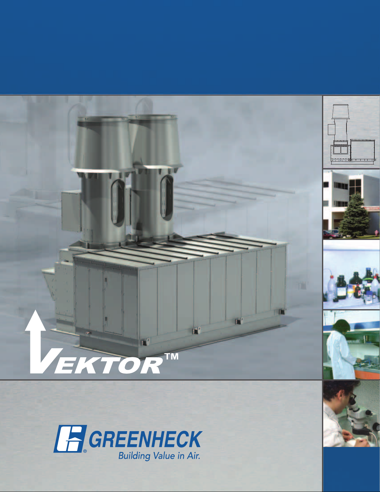
Energy Recovery Laboratory Exhaust
Model Vektor ERS-MD
For Vektor™-MD Fan Systems
March
2010
Page 2
Model Vektor ERS-MD
Page Header
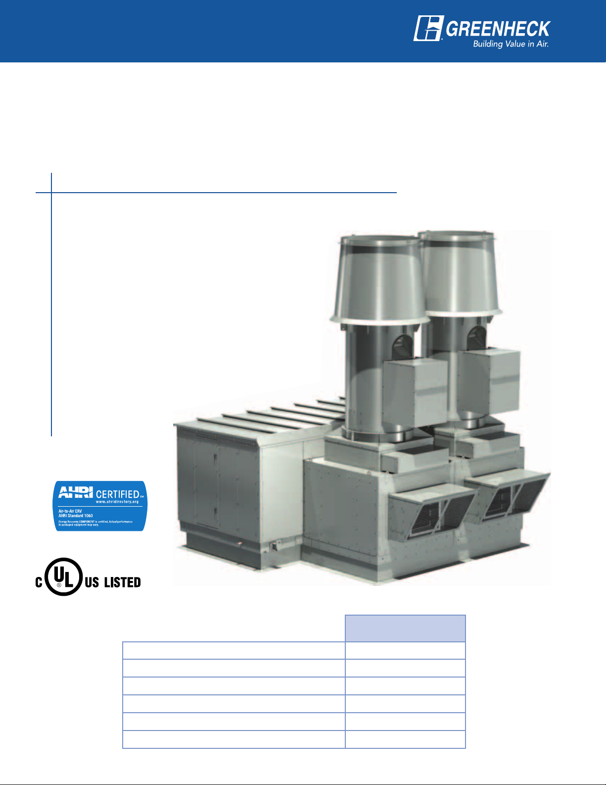
Greenheck’s Vektor™-ERS is a pre-engineered laboratory exhaust energy recovery system. In combination
with our Vektor™-MD high plume dilution blowers, this system is designed to effectively remove contaminated
laboratory exhaust and dilute and disperse the exhaust high above the roof.
Vektor energy recovery exhaust systems utilize run around coils to recover energy from the exhaust airstream
and apply the energy to the make-up air system. Vektor ERS offers a safe and efficient solution to minimize the
possibility of cross-contamination between exhaust and supply airstreams. Vektor ERS run around coil loops can
achieve energy recovery efficiencies up to 50% to lower heating and cooling costs for the laboratory facility.
Did you know…
Laboratories typically require 100% outside air with ventilation rates
ranging from 6 to 15 air changes per hour.
ASHRAE 90.1 indicates that energy recovery to pre-
conditioned make-up air is a suggested energy savings
method for laboratories in excess of 15,000 CFM.
NFPA 45 states only general exhaust can utilize air-
to-air energy recovery due to the potential of cross
contamination, which is a violation of standard. Vektor
ERS utilizes air-to-liquid energy recovery, eliminating
the possibility of cross-contamination and recover
more exhaust energy.
Studies show that approximately 50% of the energy
costs associated with operating a
laboratory are by the heating
and cooling of makeup air. The addition of
energy recovery can
significantly reduce
this cost.
Model Vektor™-MD is listed
for electrical (UL/cUL 705).
File No. E40001
Type of Heat Transfer Sensible
Run Around Coil Loop
Specifications
Sensible Effectiveness % Up to 50%
Location of Exhaust/Supply Airstream Separate
Cross-Contamination None
Cross-Leakage None
Temperature Range -45° to 200°F
2
Page 3
Page Header
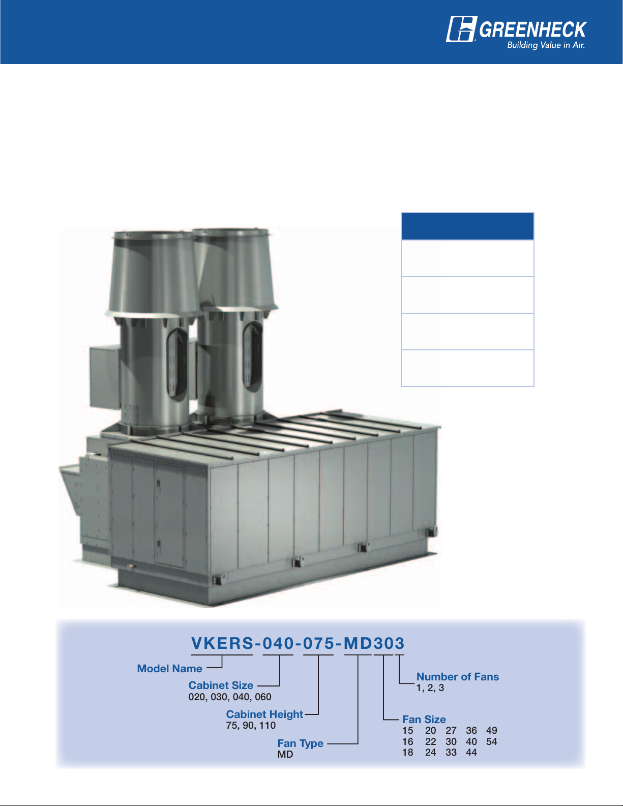
VKERS - 04 0 -0 7 5- M D3 0 3
Model Name
Cabinet Size
020, 030, 040, 060
Number of Fans
1, 2, 3
Cabinet Height
75, 90, 110
Fan Type
MD
Fan Size
15 20 27 36 49
16 22 30 40 54
18 24 33 44
Vektor ERS Features:
• Four pre-engineered energy recovery plenum sizes
• Heresite coated coils
• Insulated double-wall plenum with stainless steel
interior
• Run around coil loop energy recovery
• Coil bypass option
• Physical separation between exhaust and supply
• Single source responsibility
Vektor MD Features:
• High plume, induced flow dilution blower
• Utilizes an efficient and quiet mixed flow impeller
• Bifurcated fan housing with motor, drive, and
bearings located out of the airstream for safe, easy
servicing
• AMCA 260 licensed for Induced Flow Fans
• Single source responsibility
Performance Ranges
VKERS-020
Up to 20,000 cfm
VKERS-030
12,500 - 30,000 cfm
VKERS-040
17,000 - 43,000 cfm
VKERS-060
30,000 - 60,000 cfm
Applications
• University
Laboratories
• Pharmaceutical
Companies
• Biosafety
Laboratories
• Research Facilities
• Any contaminated
exhaust system
where reducing
energy cost is
desired
3
Page 4

ERS System Operation
Page Header
The Vektor ERS uses a corrosion-resistant run around liquid coil loop to recover energy from the laboratory
exhaust airstream and transfer the energy to the laboratory make-up air. The energy transfer preheats make-up
air in the winter and precools make-up air in the summer.
Diluted High
Plume Exhaust
Reheat Coil
Cooling Coil
VAV Bypass
Air
Vektor
Energy Recovery Coil
Filters
Pump
Exhaust
Make-Up
Air Unit
Glycol Loop
Supply
Energy Recovery Coil
Filters
Outside
Air
Safe, Reliable, Cost-Effective
The run around coil loop is the preferred method of recovering energy from hazardous lab exhaust because
separation is maintained between the exhaust and supply airstreams, eliminating the concern of crosscontamination. The exhaust coil is corrosion-resistant coated and in subfreezing climates, a percentage of glycol
is added to depress the freezing point of the circulated fluid. The Vektor ERS system also eliminates the need to
duct large volumes of supply and exhaust air to a common point—which is required with other energy recovery
systems—reducing the Vektor ERS system installed cost and improving economic payback.
Significant Energy Savings
The Vektor ERS can significantly
reduce a laboratory facility’s
heating and cooling load. The
tables illustrate preheating and
precooling temperatures of
make-up air and load reductions
for various cities based on
standard weather bin data.
Greenheck offers a complete
thermodynamic and economic
analysis of a Vektor ERS for your
specific project.
Outdoor Air
Temperature (°F)
Preheat Air
Temperature (°F)
Preconditioning of make-up air based upon 72° exhaust and 45% energy recovery efficiency.
City
Syracuse 9,458,475 (1,594,125) $90,887
Portland 3,528,330 (1,647,263) $59,063
Atlanta 7,556,153 (1,657,890) $42,303
Chicago 13,677,593 (1,657,890) $86,261
Cincinnati 13,794,495 (1,594,125) $75,385
Boston 8,927,100 (1,657,890) $77,779
Energy saving shown for annual operation, at outdoor TMY2 bin data for the specified location.
Systems operating at 50,000 cfm, equal supply and exhaust; $0.1/kwh, and $1.75/mmbtu,
assuming 80% heating efficiency.
NOTE: kwh and mmbtu costs may vary by locale.
Winter / Preheated Summer / Precooled
-10 0 10 20 30 85 95 105
26.9 32.4 37.9 43.4 48.9 79.2 84.7 90.2
BTUH Saved Annually
Heating Cooling
Net Dollars Saved
Annually
4
Page 5

Dimensions, Weights and
Bypass Air Inlet (typical)
for VAV Systems
Page Header
Configurations
E
C
A
A (Length) B (Width)
Maximum Minimum Maximum Minimum Maximum 75 90 110
VKERS-020 120 133 153
VKERS-030 154 127 181 70 84 4042 4644 NA
VKERS-040 206 147 181 70 84 5117 5824 NA
VKERS-060 270 147 181 70 84 6609 7515 8001
Coil Section Height*
75 90 110
C
D
“A” Inlet
Vertical Airflow
B
D
Fan Section Height*
70 70 3564 4386 NA
“B” Inlet
Horizontal Airflow
Weight** (pounds)
E Overall System Height
Fan Size 15 16 18 20 22 24 27 30 33 36 40 44 49 54
Minimum 145 147 161 174 169 177 193 202 194 201 209 225 240 250
Maximum 145 161 175 188 183 191 207 216 208 215 223 239 254 264
Dimensions shown in inches.
* = Curb not included
** = Approximate weight based on maximum coil size and maximum number of filters. Fans, bypass plenums and roof curbs
are not included. Obtain from CAPS (Computer Aided Product Selection).
Available Configurations
1x1 2x1 3x1
Bypass Air Inlet (typical)
Vektor MD Selections by Cabinet Size
1x1 2x1 3x1
VKERS-020 VK-MD 15-36 VK-MD 15-22 Not available
VKERS-030 VK-MD 20-44 VK-MD 15-33 VK-MD 15-22
VKERS-040 VK-MD 24-50 VK-MD 24-54 VK-MD 20-27
VKERS-060 VK-MD 40-54 VK-MD 30-54 VK-MD 24-40
Consult factory for additional configuration options.
for VAV Systems
5
Page 6

Vektor™ ERS Standard
Page Header
Construction Features
Cabinet Construction
A
• Coated steel exterior with stainless steel interior
• Double-wall construction with two-inch foam filled panels
• Stainless steel fasteners
• Bottom or side inlet locations
• Hinged access door with “tooled entry” handles
• Optional coil bypass design
Coil Construction
B
• Aluminum fins with copper tubing, corrosion-resistant
Heresite coated
• Stainless steel casing, corrosion-resistant Heresite coated
• Sized for maximum velocity of 500 ft/min
• Six row coils, eight fins per inch (standard)
• Rated in accordance with ARI 410-2001
• UL and ETL recognized
• Leak tested under water at 450 PSIG dry nitrogen
E
Filters
C
• Two-inch up to 35% disposable pleated filters, MERV 8
(0.24 inch wg pressure drop at 500 ft/min)
• Four-inch up to 65% disposable pleated filters, MERV 11
(0.40 inch wg pressure drop at 500 ft/min)
Fan Plenum Curb
D
• 12 gauge welded steel, coated with LabCoat™
• Insulated
• Minimum of 12 inches high
• Gasket provided for curb seal
• Designed to withstand 125 mph wind-load rating
without the use of guy wires
G
Vektor Sure-Aire™…another energy saving system from Greenheck
Continuously monitor critical laboratory fan exhaust
and building exhaust flow without airflow probes in the
exhaust airstream. Sure-Aire™ offers:
• Continuously measures critical fan and laboratory
exhaust flow
• Reports values to Building Automation System (BAS)
• No system effect or resistance to airflow
• No additional pressure loss
• No increase in fan RPM, sound or brake horsepower
• No additional energy cost for the building owner
• No probe corrosion to cause fan failure
Fan Flow Measurements
Output
to BAS
Bypass Airflow Measurements
G
6
Page 7

Page Header
A
F
B
C
Fan Construction
E
• Efficient and quiet mixed flow impeller technology
• Bifurcated housing with motor, belt and bearings out of
the airstream
• Corrosion-resistant welded steel construction, coated
with LabCoat™
• Belt or direct drive
• Totally Enclosed Fan Cooled, Premium Efficient motors
Fan Plenum Construction
F
• Single or double wall construction
• Exterior steel walls coated with LabCoat™
• Interior walls available in stainless or coated steel
with LabCoat™
Damper Features
G
• Isolation damper completely accessible from
exterior of system
• Bypass damper(s) are sized to match system
requirements
• Corrosion-resistant polyester resin coated,
welded steel airfoil blade design
D
Coil Cabinet Curb
H
• 12 gauge corrosion-resistant welded steel, coated
with LabCoat™
• Insulated
H
• Minimum of 12 inches high
• Gasket provided for curb seal
• Designed to withstand 125 mph wind-load rating
without the use of guy wires
Vektor ERS Options and Accessories
Magnehelic Gauge
To measure air pressure
drop across the filters
indicating filter loading.
Vapor Tight Lights
Moisture- and corrosionresistant construction with
no exposed parts. Energyefficient, compact fluorescent
lamps.
7
Page 8

Model Comparison and
Warranty Information
Family
of Lab
Exhaust
Systems
U.S. Patents:
7048499; 7320636
Mexico Patents:
243465, 258949
China (PR) Patent:
CN1294361C
Singapore Patents:
124106, 124135
Other Patents
Pending
Vektor-H Vektor-MD Vektor-CD
Housing Style Inline Centrifugal Inline Mixed Flow Single Width Centrifugal
Stack Style High Plume Nozzle High Plume Dilution Nozzle & Windband High Plume Dilution Nozzle & Windband
Minimum Flow 270 cfm (460 m³/hr) 1,500 cfm (2,550 m³/hr) 500 cfm (850 m³/hr)
Maximum Flow 24,000 cfm (40,800 m³/hr) 80,000 cfm (136,000 m³/hr) 140,000 cfm (238,000 m³/hr)
Maximum ESP Up to 3.5 in. wg (875 Pa) Up to 8 in. wg (2000 Pa) Up to 14 in. wg (3500 Pa)
UL for Electrical 705 Power
Ventilators (File no. E40001) and
Grease Removal 762 Power
Ventilators for Restaurant Exhaust
Appliances (File no. MH11745)
AMCA
Certification
Warranty 1 Year 3 Years 3 Years
Sound and Air Performance
AMCA 210 & 300
UL/cUL for Electrical 705 Power Ventilators
(File no. E40001)
Induced Flow Fan Air and
Sound Performance AMCA 210, 260, 300
U.S. Patent:
124105
Other Patents
Pending
UL/cUL for Electrical 705 Power Ventilators
Sound Performance AMCA 210, 260, 300
(File no. E40001)
Induced Flow Fan Air and
Our Warranty
Greenheck warrants this equipment to be free from defects in material and workmanship for a period
of one year from the shipment date. Any units or parts which prove defective during the warranty
period will be replaced at our option when returned to our factory, transportation prepaid. Motors are
warranted by the motor manufacturer for a period of one year. Should motors furnished by Greenheck
prove defective during this period, they should be returned to the nearest authorized motor service
station. Greenheck will not be responsible for any removal or installation costs.
As a result of our commitment to continuous improvement, Greenheck reserves the right to change
specifications without notice.
P.O. Box 410 • Schofield, WI 54476-0410 • Phone (715) 359-6171 • greenheck.com
Copyright © 2010 Greenheck Fan Corp.
00.LAB.1009 R3 3-2010 RG
Prepared to Support
Green Building Efforts
 Loading...