

Page 1

Report any damaged equipment to the
shipper immediately!
All units are shipped on a skid or packaged to minimize damage
during shipment. The transporting carrier has the responsibility
for delivering all items in their original condition as received from
Greenheck. The individual receiving the equipment is responsible
for inspecting the unit for obvious or hidden damage, recording
any damage on the bill of lading before acceptance and filing a
claim (if required) with the final carrier. Some accessory items
are stored inside the unit during shipping. Care must be taken
during installation to prevent damage to units.
**WARNING**
Disconnect and secure all electrical power to the “OFF” position prior to inspection or servicing. Failure
to comply with this safety precaution could result in serious injury or death.
Improper installation, adjustment, alteration, service or maintenance can cause property damage, injury
or death. Read the installation, operating, and maintenance instructions thoroughly before installing or
servicing this equipment.
READ AND SAVE THESE INSTRUCTIONS
Installation, Operation and Maintenance Manual
Model VFCD
Vertical Fan Coil
PN 468361
Table of Contents
Unit Layout & Table of Parts . . . . . . . . . . . . . . . . . . . . . . . . . . . . . . . . . . . . . . . . . . . . . . . . . . . . . . . . . . . . . . . . . . . . . . . . . . . . 2
Lifting & Mounting Instructions . . . . . . . . . . . . . . . . . . . . . . . . . . . . . . . . . . . . . . . . . . . . . . . . . . . . . . . . . . . . . . . . . . . . . . . . . 2
Model Dimensions, Weight & Filter Information. . . . . . . . . . . . . . . . . . . . . . . . . . . . . . . . . . . . . . . . . . . . . . . . . . . . . . . . . 3
Hot Water & Steam Coil Information. . . . . . . . . . . . . . . . . . . . . . . . . . . . . . . . . . . . . . . . . . . . . . . . . . . . . . . . . . . . . . . . . . . . 4
Chilled Water & DX Coil Information . . . . . . . . . . . . . . . . . . . . . . . . . . . . . . . . . . . . . . . . . . . . . . . . . . . . . . . . . . . . . . . . . . . . 5
Airflow Start-up. . . . . . . . . . . . . . . . . . . . . . . . . . . . . . . . . . . . . . . . . . . . . . . . . . . . . . . . . . . . . . . . . . . . . . . . . . . . . . . . . . . . . . . . . 6
Speed Controls . . . . . . . . . . . . . . . . . . . . . . . . . . . . . . . . . . . . . . . . . . . . . . . . . . . . . . . . . . . . . . . . . . . . . . . . . . . . . . . . . . . . . 6 - 7
Airflow Troubleshooting . . . . . . . . . . . . . . . . . . . . . . . . . . . . . . . . . . . . . . . . . . . . . . . . . . . . . . . . . . . . . . . . . . . . . . . . . . . . . . . . 7
Hot Water, Chilled Water & DX Coil Start-Up Instructions . . . . . . . . . . . . . . . . . . . . . . . . . . . . . . . . . . . . . . . . . . . . . . 8
Steam Coil Start-Up Instructions . . . . . . . . . . . . . . . . . . . . . . . . . . . . . . . . . . . . . . . . . . . . . . . . . . . . . . . . . . . . . . . . . . . . . . . 9
Fan Maintenance Instructions . . . . . . . . . . . . . . . . . . . . . . . . . . . . . . . . . . . . . . . . . . . . . . . . . . . . . . . . . . . . . . . . . . . . . . . . . 10
Coil Maintenance Instructions. . . . . . . . . . . . . . . . . . . . . . . . . . . . . . . . . . . . . . . . . . . . . . . . . . . . . . . . . . . . . . . . . . . . . . . . . 11
Maintenance Documentation & Warranty. . . . . . . . . . . . . . . . . . . . . . . . . . . . . . . . . . . . . . . . . . . . . . . . . . . . . . . . . . . . . . 12
®
Page 2
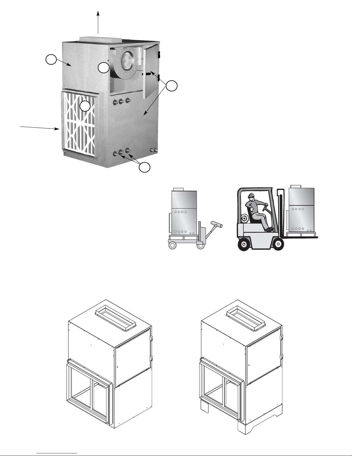
Lifting Instructions
Greenheck's Vertical Fan Coil (VFCD) can be
moved a round a job site on a wheeled cart or
with a forklift. Avoid twisting or uneven lifting of
equipment. Do not lift equipment by coil
connections or headers. The unit must remain
upright during lifting. All access doors and panels
must be closed during lifting to avoid damage.
Mounting Instructions
The VFCD should be mounted on a field supplied base as shown in Figure 2. An optional Greenheck supplied 6
inch extended base may be used when mounting as shown in Figure 3. The VFCD is available with both
external neoprene and spring isolation options.
2
1. Fan Section
2. Coil Section
Chilled Water or DX Coils
Hot Water or Steam Coils
3. Inlet Filter
Vertical inlet filter with
1
⁄4 turn fasteners
(Removed for internal viewing)
4. Side Access Panels
Right and left access to each unit
(upper panel hinged open)
5. Knockout for recommended
electrical wiring penetration or
disconnect switch.
1
2
3
4
Airflow
5
Airflow
Figure 3Figure 2
Page 3
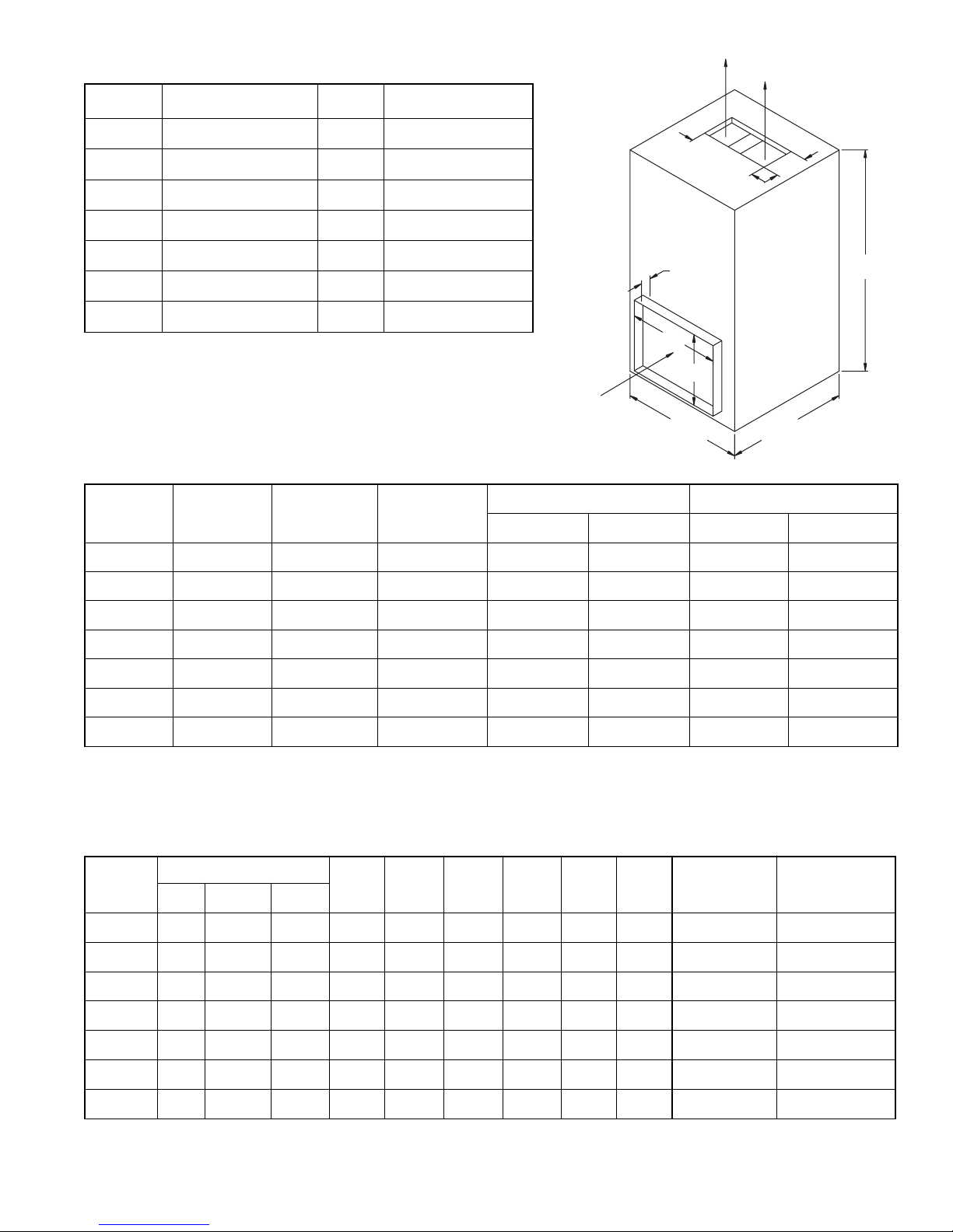
Outlet
Air Flow
Inlet
Air Flow
Height
Depth
Width
Filter
Projection
2 or 4 in.
H
W
H
W
3
VFCD Weight Information
VFCD Dimensional Data
VFCD Filter Information
All weights are shown in lbs. Motor weights may very depending on enclosure type and horsepower.
All dimensions are shown in inches.
Unit Size Height Width Depth
Inlet
Outlet
Width Height Width Height
600
40 24 24 18 22 7 51⁄2
800
40 24 24 18 22 7 51⁄2
1300
44 24 28 18 22 18 55⁄8
1600
44 30 28 22 22 18 55⁄8
2000
52 34 28 29 23 26 55⁄8
2400
52 34 28 29 23 26 55⁄8
3000
52 50 28 45 22 327⁄8 103⁄8
Unit Size
Fan w/ Drain Pan
Row 1 Row 2 Row 4 Row 6 Row 8
Row102 in. Vertical
Filter
4 in. Vertical
Filter
Fan Motor Total
600
235 60 295 38 51 77 106 135 - 8 13
800
240 60 300 38 51 77 106 135 - 8 13
1300
260 60 320 38 51 77 106 135 164 8 13
1600
300 60 360 51 70 110 152 195 238 11 17
2000
350 75 425 58 80 127 175 225 275 12 19
2400
360 75 435 58 80 127 175 225 275 12 19
3000
425 75 500 64 90 143 198 225 252 14 22
All dimensions are shown in inches.
Size Filter Size Qty
Face Area ft.
2
600
20 x 24 1 2.7
800
20 x 24 1 2.7
1300
20 x 24 1 2.7
1600
24 x 24 1 3.6
2000
16 x 25 2 4.7
2400
16 x 25 2 4.7
3000
24 x 24 2 6.7
Page 4
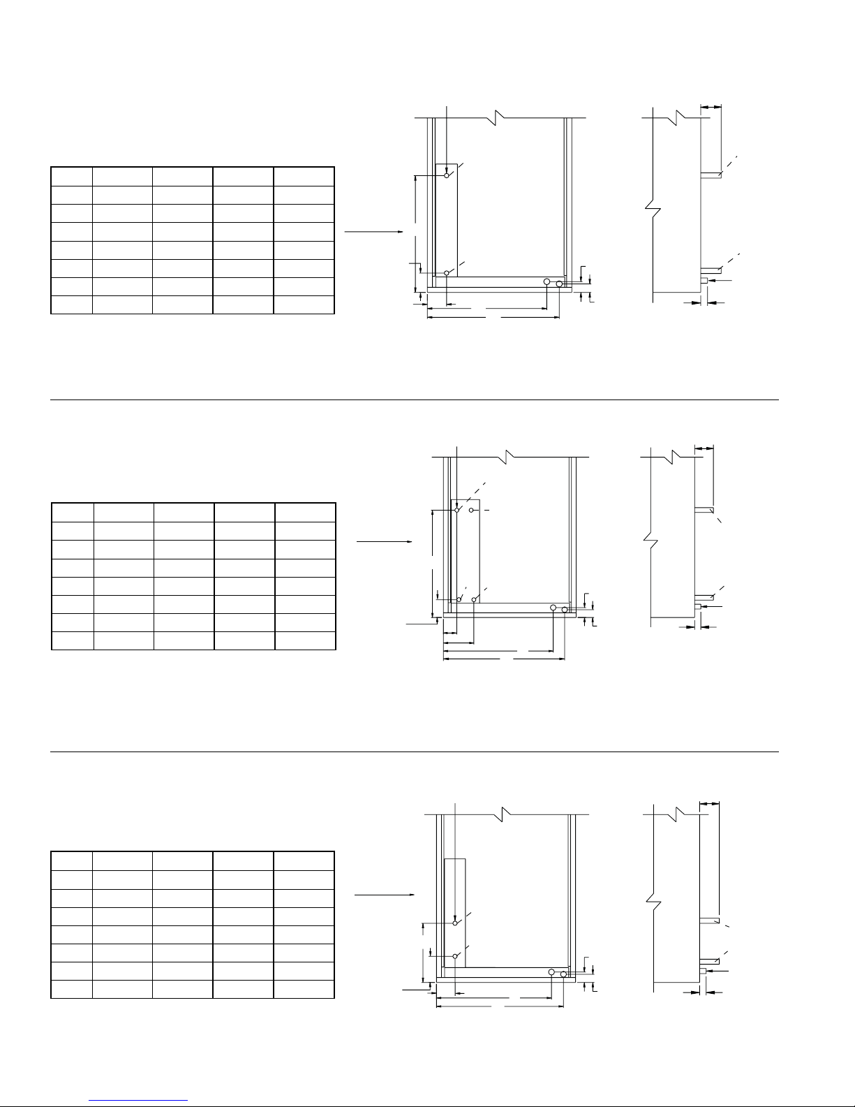
4
Hot Water
1 & 2 Row
Dimensional Data
VFCD Coil Data
NOTE: Fluid enters the coil from the bottom connection (Inlet)
and exits from the top (Outlet).
All dimensions are in inches.
Hot Water
4 Row
Steam
1 & 2 Row
Dimensional Data
Dimensional Data
All dimensions are in inches.
NOTE: Steam enters the coil from the center connection (Inlet)
and exits from the bottom (Outlet).
NOTE: With airflow from left to right the fluid enters the coil from
the bottom connection (Inlet) and exits from the top (Outlet). The
other two coil connections should be capped off.
All dimensions are in inches.
0.25 Vent and Drain Supplied
Right Side Connection Shown
0.25 Vent and Drain Supplied
Right Side Connection Shown
Right Side Connection Shown
Size A B C D
600 20.00 22.50 22.63 0.875
800 20.00 22.50 22.63 0.875
1300 24.00 27.50 22.63 0.875
1600 24.75 27.25 22.63 0.875
2000 24.75 27.50 25.13 0.875
2400 24.75 27.50 25.13 0.875
3000 28.75 31.25 22.63 1.375
Size A B C D
600 20.00 22.50 22.63 0.875
800 20.00 22.50 22.63 0.875
1300 24.00 27.50 22.63 0.875
1600 24.75 27.25 22.63 0.875
2000 24.75 27.50 25.13 0.875
2400 24.75 27.50 25.13 0.875
3000 28.75 31.25 22.63 1.375
Size A B C D
600 20.00 22.50 13.20 2.0
800 20.00 22.50 13.20 2.0
1300 24.00 27.50 13.20 2.0
1600 24.75 27.25 13.20 2.0
2000 24.75 27.50 14.44 2.0
2400 24.75 27.50 14.44 2.0
3000 28.75 31.25 13.20 2.5
Airflow
C
3.75 in.
3.81 in.
Airflow
3.75 in.
C
3.38 in.
D
Outlet
Inlet
A
B
2 in.
1.5 in.
4 in.
Outlet
Inlet
0.75 in.
1 in.
Drain Connection
D
Cap
Outlet
Cap
Inlet
6.63 in.
2 in.
1.5 in.
A
B
3 in.
Outlet
Inlet
0.75 in.
1 in.
Drain Connection
Airflow
4.38 in.
D
Inlet
C
Outlet
5 in.
2 in.
A
B
1.5 in.
3 in.
Inlet
Outlet
0.75 in.
1 in.
Drain Connection
Page 5

5
Direct Expansion (DX)
Single Circuit
4, 6 or 8 Row (Orifice Code 18/19)
NOTE: With airflow from left to right the fluid enters the coil from the bottom connection (Inlet) and
exits from the top (Outlet). The other two coil connections should be capped off (Cap).
Chilled Water
4, 6 or 8 Row
VFCD Coil Data
Dimensional Data
All dimensions are in inches.
All dimensions are in inches.
Dimensional Data
0.25 Vent and Drain Supplied
Right Side Connection Shown
NOTE: With airflow from left to right the fluid enters the coil from the center connection
(Inlet) and exits from the bottom (Outlet). The other connections should be capped off.
Right Side Connection Shown
Size
A B
C D E F
4 Row 6 Row 8 Row 4 Row 6 Row 8 Row
600 3.38 3.29 3.21 6.63 8.71 10.79 20.00 22.50 22.63 0.875
800 3.38 3.29 3.21 6.63 8.71 10.79 20.00 22.50 22.63 0.875
1300 3.38 3.29 3.21 6.63 8.71 10.79 24.00 27.50 22.63 0.875
1600 3.38 3.29 3.21 6.63 8.71 10.79 24.75 27.25 22.63 0.875
2000 3.38 3.29 3.21 6.63 8.71 10.79 24.75 27.50 25.13 0.875
2400 3.38 3.29 3.21 6.63 8.71 10.79 24.75 27.50 25.13 0.875
3000 3.38 3.29 3.21 6.63 8.71 10.79 28.75 31.25 22.63 1.375
Size
A B
C D E
4 Row 6 Row 8 Row 4 Row 6 Row 8 Row
600 3.38 3.29 3.21 5.66 6.25 7.33 20.00 22.50 13.19
800 3.38 3.29 3.21 5.66 6.25 7.33 20.00 22.50 13.19
1300 3.38 3.29 3.21 5.66 6.25 7.33 24.00 27.50 13.19
1600 3.38 3.29 3.21 5.66 6.25 7.33 24.75 27.25 13.19
2000 3.38 3.29 3.21 5.66 6.25 7.33 24.75 27.50 14.44
2400 3.38 3.29 3.21 5.66 6.25 7.33 24.75 27.50 14.44
3000 3.38 3.29 3.21 5.66 6.25 7.33 28.75 31.25 13.19
F
Airflow
E
3.75 in.
Outlet
Cap
Cap
Inlet
A
B
C
D
2 in.
1.5 in.
3 in.
Outlet
Inlet
0.75 in.
1 in.
Drain Connection
1.625 in.
1.125 in.
Airflow
E
3.75 in.
Cap
Inlet
Outlet
A
B
C
D
2 in.
1.5 in.
3 in.
Cap
Inlet
Outlet
0.75 in.
1 in.
Drain Connection
Page 6

6
Airflow System Start-Up
For proper unit function and safety, follow everything in this start-up procedure in the order presented. This is
to be done after the electrical connections are complete.
1. Check Voltage
Before starting the unit compare the supplied
voltage with the units nameplate voltage and the
motor voltage.
2. Check Blower Rotation
If the blower is rotating in the wrong direction, the
unit will move some air but not perform properly.
To check the rotation, open the blower access
door and run the blower momentarily to determine
the rotation.
To reverse the rotation, turn the power off and use
the following procedure:
• For single phase units,
rewire the motor per
the instructions on
the motor.
3. Check for Vibration
Check for unusual noise and vibration. Excessive
vibration maybe experienced during initial startup. Left unchecked, excessive vibration can
cause a multitude of problems, including
structural and/or component failure. Many
conditions can be discovered by careful
observation. If the problem is wheel unbalance,
in-place balancing can be done providing there is
access to the fan wheel. Generally, fan vibration
and noise is transmitted to other parts of the
building by the ductwork. If noise is an issue, we
recommend using heavy canvas connections on
the inlet of the fan. Refer to the “Troubleshooting”
section of this manual if a problem develops.
4. Air Volume Check and Measurement
Along with the building balance, the units air
volume (cfm) should be measured and compared
with its rated air volume. This unit is flexible for
varying air volume, but the actual air volume
should be known for making final adjustments.
The most accurate way to measure the air volume
is by using the pitot traverse method in the
ductwork away from the blower. Other methods
can be used but should be proven and accurate.
To adjust the air volume, change the fan rpm or
the system losses. See Troubleshooting section in
this guide.
5. Measure Motor Voltage, Amperage and
Fan rpm
All access doors must be installed. Measure and
record the input voltage and motor amperage(s).
To measure the fan rpm, the blower door will need
to be removed. Minimize measurement time
because the motor may over amp with the door
removed.
Compare measured amps to the motor nameplate
full load amps and correct if over amping. See the
Troubleshooting section in this guide.
Pre-Start Check List
1. Disconnect and lock-out all power switches to
fan.
2. Check all fasteners, set screws and locking
collars on the fan, motor base and accessories
for tightness.
3. Rotate the fan wheel by hand and assure no
parts are rubbing.
Special Tools Required
• Voltage meter
• Tachometer
• Amperage meter
AIRFLOW
R
O
T
A
T
O
I
N
Speed controls may be used on Model VFCD fans for
manual adjustment of the fan’s performance (for final
system balancing) or to control the fan’s output in
confined spaces, such as conference or meeting
rooms. The fan can be adjusted to 60% of design
airflow with a speed control. This reduction in airflow
and fan speed is also accompanied by a reduction in
noise level. Solid state speed controls are available for
a range of applications up to 15 amps. Speed controls
can be used to operate more than one fan if the
combined total amperage of the fans does not exceed
the control rating.
Model 5WSSC - For use w/ shaded pole and PSC motors.
• Rated for 115 - 127V, 5 Amp • UL Listed
• Require a 2x4 handy box
Model 5W240 - For use w/ shaded pole and PSC motors.
• Rated for 220 - 240V, 5 Amp • UL Listed
• Requires 2x4 handy box
Speed Controls
Page 7

Model 8WSSC - For use w/ shaded pole and PSC motors.
• Rated for 220 - 240V, 8 Amp • UL Listed
• Requires 2x4 handy box
Model 10WSSC - For use w/ shaded pole and PSC motors.
• Rated for 115 - 127V, 10 Amp • UL Listed
• Requires 4x4 handy box
Airflow Troubleshooting
7
Blower Unit
Symptom Possible Cause Solution
Blower fails Blown fuse or open circuit breaker Replace fuse or reset circuit breaker and
to operate check amps
Defective motor or capacitor Replace
Motor starter overloaded Reset starter and check amps
Motor overamps CFMs too high Check CFMs
Static pressures are higher or lower If higher, ductwork should be improved
than design If lower, fan RPMs should be lower
Blower rotation is incorrect Check rotation and correct
Motor voltage incorrect Check motor nameplate and supplied voltage
Motor horsepower too low See specifications and catalog for fan
curves to determine if horsepower is sufficient
Shorted windings in motor Replace motor
Insufficient airflow Mixing box damper not fully open Adjust damper linkage or replace
damper motor
System static pressure too high Improve ductwork to eliminate losses
using good duct practices
Blower speed too low Check for correct RPMs with catalog data
Mixing box dampers closed Open and adjust
Dirty or clogged filters Clean or replace
Leaks in ductwork Repair
Elbows, or other obstructions
Correct or improve ductwork
may restrict fan outlet
Too much airflow Blower fan speed too high Check for correct fan RPM
Filter(s) not in place Install filters
Insufficient static pressure (SP) Induce SP into system ductwork
(airflow resistance)
Excessive noise Wheel rubbing on housing Center wheel
or vibration
Loose wheel on shaft Tighten wheel setscrew
Loose motor or blower sheave Tighten sheave setscrew
Motor base or blower loose Tighten mountings bolts
Motor out of balance Replace
Wheel out of balance Replace or rebalance
Accumulation of material on wheel Clean wheel and housing
FULL VOLTAGE
H
BLACK
SPEED CONTROL
RED
WHITE
SWITCHED FULL VOLTAGE
Dotted line indicates
for use with 10W
switch only.
VARIABLE
VOLTAGE
AUX
DEVICE
120 VAC
FAN
N
Page 8

8
Water Coils
1. Piping should be in accordance with accepted industry standards. Pipework should be supported
independently of the coils. Water pipes are copper with sweet connections. USE WET TOWEL TO AVOID
BURNING COIL CONNECTION GROMMETS. When installing coupling, do not apply undue stress to the
connection extending through the unit. Use a back-up pipe wrench to avoid breaking the weld between
coil connection and header.
2. Connect the WATER SUPPLY TO THE BOTTOM CONNECTION on the air-leaving side and the WATER
RETURN TO THE TOP CONNECTION on the air-entering side. The extra bottom connection can be used
for an auxiliary manual drain connection, and the extra top connection may be used for an automatic air
vent or the extra connections can be capped. To insure proper venting, an external air vent in the piping
is recommended. Connecting the supply and/or return in any other manner will result in very poor
performance. CAP UNUSED CONNECTIONS.
3. The air vent at the uppermost point should be temporarily opened during system start-up to release all
of the air from the coil. To maintain heat transfer capacity, periodically vent any air in coil. Vent is
to be located behind connections side access door.
4. Water coils are not normally recommended for use with entering air temperatures below 40ºF. No control
system can be depended on to be 100% safe against freeze-up with water coils. Glycol solutions or
brines are the only safe media for operation of water coils with low entering air conditions.
CONTINUOUS WATER CIRCULATION THROUGH THE COIL AT ALL TIMES IS HIGHLY RECOMMENDED.
5. Pipe sizes for the system must be selected on the basis of the head (pressure) available from the
circulation pump. Piping should be in accordance with accepted industry standards.
6. For chilled water coils, the condensate drain pipe should be sized adequately to ensure the condensate
drains properly. See DRAIN PAN TRAPS and Figure 4.
Direct Expansion (DX) Coils
1. Piping should be in accordance with accepted industry standards. Pipework should be supported
independently of the coils. Undue stress should not be applied at the connection to coil headers.
2. The condensate drain pipe should be sized adequately to ensure the condensate drains properly. See
DRAIN PAN TRAPS and Figure 4.
3. When connecting suction and liquid connections make sure the coil is free from all foreign material. Make
sure all joints are tight and free of leakage.
4. Dual circuits are recommended to be run by two compressors. One compressor with the appropriate
valves and piping can be used but is not recommended. Greenheck does not supply compressor or
condensing units, for further instruction on DX coil installation and operation contact your compressor
and/or condenser manufacturer.
DXI coils have dual connections and should be used with two compressors.
Drain Pan Traps
Drain lines and traps should be run full size from
the drain pan connection. Drain pans should have
drain lines and traps to permit the condensate
from the coils to drain freely. On all units with drain
pans, the trap depth and the distance between the
trap outlet and the drain pan outlet should be
twice the static pressure in the drain pan section
under normal operation to assure the trap remains
sealed.
Figure 4 - Drain Pan Trap
Hot Water, Chilled Water & DX Coils
2P = min.
2P = min.
Page 9

Steam Coils
Application Recommendations:
Satisfactory operation and service life are best ensured when coils are installed with proper piping, trap, and
support arrangement. The following notes and Figure 5 are recommended for the coil unit installation and
operation.
General:
1. Provide separate supports and hangers for the unit and the piping.
2. Be certain that adequate piping flexibility is provided. Stresses resulting from expansion of closely
coupled piping and coil arrangement can cause serious damage.
3. Standard steam coils are pitched in the casings when installed for horizontal air flow. The casing must
BE LEVEL after the unit is installed for proper condensate drainage. If condensate is not removed the coil
will suffer from water hammering and will have a shortened life. On vertical air flow applications, the coils
must be pitched when installed.
4. Do not reduce pipe size at the coil return connection. Carry return connection size through the dirt
pocket, making the reduction at the branch leading to the trap.
5. It is recommended that vacuum breakers be installed on all applications to prevent retaining condensate
in the coil. Generally, the vacuum breaker is to be connected between the coil inlet and the return main.
The vacuum breaker should be open to the atmosphere and the trap design should allow venting of large
quantities of air.
6. Do not attempt to lift condensate when using modulating or on-off control.
7. Do not reduce the pipe size leaving the coil.
Traps:
1. Size traps in accordance with the manufacturer’s recommendations. Be certain that the required pressure
differential will always be available. DO NOT UNDERSIZE.
2. Float and thermostatic or bucket traps are recommended for low pressure steam. On high pressure
systems, bucket traps are normally recommended. The thermostatic traps should be used only for air
venting.
3. Bucket traps are recommended for use with on-off control only.
4. Locate traps at least 12 inches below the coil return connection.
Controls:
1. On high pressure installations, a two-position steam valve with a face and bypass arrangement is
preferred where modulating control is required.
2. Modulating valves must be size properly. DO NOT UNDERSIZE.
Freezing Conditions (Entering air below 35ºF):
1. 5 PSI steam must be supplied to the coil at all times.
2. Modulating valves are not recommended. Control should be by means of face and bypass dampers.
3. Provision should always be made to thoroughly mix fresh air and
return air before it enters the coil on return air units.
Also, temperature control elements must be
properly located to obtain true air mixture
temperatures.
4. As additional protection against freezeup, the trap should be installed
sufficiently far below the coil to provide
an adequate hydrostatic head to ensure
removal of condensate during an
interruption in the steam pressure.
Estimate 3 feet for each 1 PSI of trap
differential required.
5. On start up, admit steam to coil ten
minutes before admitting outdoor air.
6. Provision must be made to close fresh air
dampers if steam supply pressure falls
below minimum specified.
r
Figure 5
Recommended Steam Coil Piping
9
Steam Main
Return Main
Gate Valve
Control Valve, Modulating
Two-Position
Check Valve-Vacuum Breake
Float and Thermostat Trap
Strainer
Page 10

10
Fan Maintenance
Greenheck recommends these procedures to insure trouble free operation of this unit. It is especially important
to maintain heater units for clean and efficient operation. Most unit failures can be attributed to poor setup or
poor maintenance.
A record of maintenance performed on this unit should be kept. This information will provide essential
information if problems are encountered. A section at the back of this manual is provided for recording the
unit's maintenance history.
CAUTION: When performing any maintenance on this unit be sure that the power is disconnected and
cannot be accidentally turned on. The control center disconnect can be locked in the off position.
Pre-Starting Checks
Check all fasteners for tightness. The wheel should rotatefreely and be aligned. Wheel position is preset at the
factory, however, movemenet may occure durig shipment and realignment may be necessary. Centering may be
accomplished by loosening hte set screw in the wheel and moving the wheel to desired position.
Every 3 Months
The filter in the unit should be inspected at least every 3 months. Depending on the environment filters could
require changing or cleaning more or less often. The filters can be slid out of either side of the unit.
If washable filters are installed, they can be washed in warm soapy water. An adhesive spray can be applied
to increase filter efficiency.
If disposable filters are installed, check by holding up to a light source. If light cannot pass through the filter, it
should be replaced. Replacement filters should be of the same manufacturer and size. When reinstalling filters,
be sure to install with the airflow in the correct direction indicated on the filter.
Motor maintenance is generally limited to cleaning and lubrication (where applicable). Cleaning should be
limited to the exterior surfaces only. Removing dust and grease build-up on motor housing assures proper
motor cooling. Greasing of motors is intended only when grease fittings are provided. Many fractional motors
are permanently lubricated and require no further lubrication. Motors supplied with grease fittings should be
greased in accordance with manufacturer's recommendations. When motor temperature does not exceed 104°F
(40°C), the grease should be replaced after 2000 hours of running time as a general rule.
Wheels require very little attention when moving clean air. Occasionally oil and dust may accumulate on the
wheel causing imbalance. When this occurs the wheel and housing should be cleaned to assure smooth and
safe operation. Inspect fan impeller and housing for fatigue, corrosion or wear
Routinely check all fasteners, set screws and locking collars on the fan, motor base and accessories for
tightness.
Page 11

11
Coil Maintenance
1. Coils must be clean to obtain maximum performance. Check once a year under normal operating
conditions and, if dirty, brush or vacuum clean. Soiled fins reduce the capacity of the coil, demand
more energy from the fan, and create an environment for odor and bacteria to grow and spread through
the conditioned zone. High pressure water (400 psi or less) may be used to clean coils with fin thickness
over 0.006 inches thick. TEST THE SPRAY PRESSURE over a small corner of the coil to determine if the
fins will withstand the spray pressure.
For coils with fragile fins or high fin density, foaming chemical sprays and washes are available. Many coil
cleaners contain harsh chemicals, so they must be used with caution by qualified personnel only. Care
must be taken not to damage the coils, including fins, while cleaning. CAUTION: Fin edges are sharp.
2. Drain pans in any air conditioning unit will have some moisture in them, therefore, algae and other
organisms will grow due to airborne spores and bacteria. Periodic cleaning is necessary to prevent this
build-up from plugging the drain and causing the drain pan to overflow. Inspect twice a year to avoid the
possibility of overflow. Also, drain pans should be kept clean to prevent the spread of disease. Cleaning
should be performed by qualified personnel.
Winterizing Coils
Coil freeze-up can be caused by such things as air stratification and failure of outdoor air dampers and/or
preheat coils. Routine draining of water cooling coils for winter shutdown cannot be depended upon as
insurance against freeze-up. Severe coil damage may result. It is recommended that all coils be drained as
thoroughly as possible and then treated in the following manner.
Fill each coil independently with an antifreeze solution using a small circulating pump and again thoroughly
drain. Check freezing point of antifreeze before proceeding to next coil. Due to a small amount of water always
remaining in each coil, there will be diluting effect. The small amount of antifreeze solution remaining in the coil
must always be concentrated enough to prevent freeze-up.
NOTE: Carefully read instructions for mixing antifreeze solution used. Some products will have a higher freezing
point in their natural state than when mixed with water.
Page 12

This manual is the property of the owner, and is required for future maintenance.
Please leave it with the owner when you complete the job.
Warranty
Greenheck warrants this equipment to be free from defects in material and workmanship for a period of one year from
the purchase date. Any units or parts which prove defective during the warranty period will be replaced at our option
when returned to our factory, transportation prepaid. Motors are warranted by the motor manufacturer for a period of one
year. Should motors furnished by Greenheck prove defective during this period, they should be returned to the nearest
authorized motor service station. Coils are warranted by the coil manufacture for a period of one year. Greenheck will not
be responsible for any removal or installation costs.
As a result of our commitment to continuous improvement, Greenheck reserves the right to change specifications
without notice.
K
®
Model VFCD IOM
#468361 Rev 1 September 2005
Copyright © 2005 Greenheck Fan Corp.
Job Information
Job Name:________________________________________
Address:__________________________________________
City: ________________ State: ________ Zip: __________
Phone: __________________ Fax: ____________________
Contact Person:___________________________________
Service Organization: _____________________________
Address:_________________________________________
City: ________________ State: ________ Zip: _________
Phone: __________________ Fax: ___________________
Work Done By: ___________________________________
Name Plate Information
Model: ___________________________________________
Volts: ___________ Hertz: __________ Phase: _________
Amps: __________________ Mark: ___________________
Serial Number: ____________________________________
Motor Voltage:
Motor Amperage:
Fan rpm:
Maintenance Documentation
Field Start-Up Documentation
Actual Voltage:
Hertz: Phase:
Actual Amperage:
Blower Rotation Correct
Air Volume Design
cfm
Actual cfm
Maintenance
Date Time Notes:
GREENHEC
P.O. BOX 410 SCHOFIELD, WISCONSIN 54476-0410
PH. 715-359-6171
www.greenheck.com
 Loading...