

Page 1
Document 476072
®
Vektor
®
with Variable Geometry Nozzle (VGN) Technology
Laboratory Exhaust
Electrical Controls Information
Installation, Operation and Maintenance Manual
Please read and save these instructions for future reference. Read carefully before attempting to assemble,
install, operate or maintain the product described. Protect yourself and others by observing all safety
information. Failure to comply with instructions could result in personal injury and/or property damage!
Table of Contents
General Safety Information ......................1
Receiving, Handling and Storage .................2
VFD Controller Nozzle Controller
General Safety Information
Only qualified personnel should install this unit.
Personnel should have a clear understanding of these
instructions and should be aware of general safety
precautions. Improper installation can result in electric
shock, possible injury due to coming in contact with
moving parts, as well as other potential hazards. Other
considerations may be required if high winds or seismic
activity are present. If more information is needed,
contact a licensed professional engineer before moving
forward.
1. Follow all local electrical and safety codes, as well as
the National Electrical Code (NEC), the National Fire
Protection Agency (NFPA), where applicable. Follow
the Canadian Electrical Code (CEC) in Canada.
2. Do not allow the power cable to kink or come in
contact with oil, grease, hot surfaces, or chemicals.
Replace cord immediately if damaged.
3. Verify the power source is compatible with the
equipment.
DANGER
Always disconnect power before working on or
near a unit. Lock and tag the disconnect switch or
breaker to prevent accidental power up.
CAUTION
When servicing the unit, variable frequency drives
(VFD) may be hot enough to cause pain or injury.
Allow motor to cool before servicing.
Component Checklist - Electrical ...............2
System Components ...........................3
Wiring Installation .............................3
Fan Operation - Single Fan
Set Point and Minimum Variables ...............4
Defined Modes .............................4
VGN Technology Control Flow Chart ............5
Fan Operation - Multiple Fans, No Staging
Set Point and Minimum Variables ...............6
Defined Modes ........................... 6-7
VGN Technology Control Flow Chart ............8
Fan Operation - Multiple Fans, With Staging
Set Point and Minimum Variables ...............9
Defined Modes ............................10
VGN Technology Control Flow Chart ...........11
Factory-Supplied Variable Frequency Drive
System Diagram .............................12
Wiring Diagram ..............................13
Communication BACnet® and LonWorks® Protocol . 14
Start-Up Procedure - Electrical Controls ..........15
System Test and Balance for VGN ...............16
Nozzle Velocity Adjustment .....................16
Customer-Supplied Variable Frequency Drive
System Diagram .............................18
Wiring Diagram ..............................19
VGN Nozzle Controller Intro. and Tutorial ....... 20-22
Communication ..............................23
Start-Up Procedure - Electrical Controls ..........24
System Test and Balance for VGN ...............25
Nozzle Velocity Adjustment .....................25
Troubleshooting ..............................26
Maintenance ................................27
Electrical Replacement Parts ...................27
Our Commitment .............................28
®
VGN Technology
1
Page 2

General Electrical Controls Information
Receiving
Upon receiving the product, check to ensure all items
are accounted for by referencing the delivery receipt or
packing list. Inspect each crate or carton for shipping
damage before accepting delivery. Alert the carrier
of any damage detected. The customer will make
a notation of damage (or shortage of items) on the
delivery receipt and all copies of the bill of lading which
is countersigned by the delivering carrier. If damaged,
immediately contact your Greenheck Representative.
Any physical damage to the unit after acceptance is not
the responsibility of Greenheck Fan Corporation.
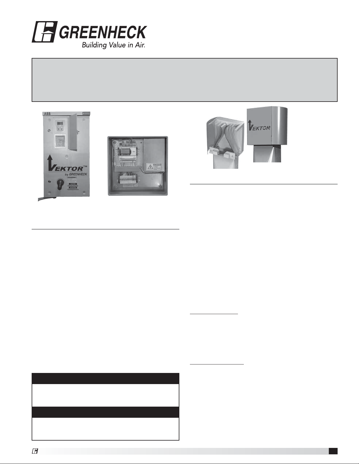
Component Checklist - Electrical
Check off the following system components to verify all
components are received.
ABB Eclipse Variable Frequency Drive (VFD) with
bypass mode and internal wiring kit.
(VGN with factory-supplied VFD)
VGN nozzle controller
(VGN customer-supplied VFD)
Transducer/terminal enclosure with Sure Aire™
pressure transducer and system terminals in
NEMA3R enclosure
24 volt VGN nozzle with modulating actuator
0/2-10 VDC with feedback
Unpacking
Verify that all required parts and the correct quantity
of each item have been received. If any items are
missing; report shortages to your local representative to
arrange for obtaining missing parts. Sometimes it is not
possible that all items for the unit be shipped together
due to availability of transportation and truck space.
Confirmation of shipment(s) must be limited to only
items on the bill of lading.
atmosphere. Remove any accumulations of dirt, water,
ice, or snow and wipe dry before moving to indoor
storage. To avoid “sweating” of metal parts, allow cold
parts to reach room temperature. To dry parts and
packages use a portable electric heater to eliminate any
moisture build up. Leave coverings loose to permit air
circulation and to allow for periodic inspection. The unit
should be stored at least 3½ in. (89 mm) off the floor on
wooden blocks covered with moisture proof paper or
polyethylene sheathing. Aisles between parts and along
all walls should be provided to permit air circulation and
space for inspection.
Inspection and Maintenance during
Storage
While in storage, inspect equipment once per month.
Keep a record of inspection and maintenance
performed. If moisture or dirt accumulations are found
on parts, the source should be located and eliminated.
Removed From Storage
As units are removed from storage to be installed
in their final location, they should be protected and
maintained in a similar fashion, until the equipment goes
into operation. Prior to installing the unit and system
components, inspect the unit assembly to make sure it
is in working order.
1. Check all fasteners, and accessories for tightness.
Handling
Handle in such a manner as to keep from scratching or
chipping the coating. Damaged finish may reduce ability
of unit to resist corrosion.
Storage
Units are protected against damage during shipment. If
the unit cannot be installed and operated immediately,
precautions need to be taken to prevent deterioration of
the unit during storage. The user assumes responsibility
of the unit and accessories while in storage. The
manufacturer will not be responsible for damage during
storage. These suggestions are provided solely as a
convenience to the user.
INDOOR - The ideal environment for the storage of
units and accessories is indoors, above grade, in a
low humidity atmosphere which is sealed to prevent
the entry of blowing dust, rain, or snow. Temperatures
should be evenly maintained between 30°F (-1°C)
and 110°F (43°C) (wide temperature swings may
cause condensation and “sweating” of metal parts).
All accessories must be stored indoors in a clean, dry
VGN Technology
2
®
Page 3
General Electrical Controls Information
System Components
System Components (supplied by Greenheck)
Quantity Description
1 Pressure transducer with adjustable pressure
range and VDC signal
1 VFD with bypass mode and integrated controller
(VGN with factory-supplied VFD)
1 VGN nozzle controller.
(VGN, customer-supplied VFD)
1 to 4 Actuator motor(s) (nozzle)
24 volts, modulating VDC signal with feedback
Varies Actuator motor (bypass damper), if provided by
manufacturer
Varies Actuator motor (isolation damper) 24 volts,
open/close. Quantity will be zero if isolation
damper actuator is supplied by others or if gravity
style isolation damper is used.
System Components (customer-supplied)
Quantity Description
Varies Wiring, conduit, miscellaneous fittings
1 Building control system with required
communication wiring and shielding
Varies Pressure transducer for duct pressure
Varies Actuator motor (bypass damper) if provided by
others
1 Actuator motor (isolation damper), if provided
by others. Quantity will be zero if gravity style
isolation damper is used.
Varies 1/4 inch tubing. Connection from Sure-Aire
termination plate mounted on fan to mounting
location of transducer/terminal enclosure.
1 Fan motor VFD.
(VGN, customer-supplied VFD)
Wiring Installation
NOTE
All field installation and wiring of electrical
equipment must be done to meet NEC and local
codes.
NOTE
Be sure to use appropriately sized wire for the full
load amp draw.
The following items are a list of requirements necessary
to install the controls for the VGN Technology system.
1. Mount variable frequency drive in the desired
location; indoors or outdoors. Maximum distance
from fan is 100 feet (30.5 meters).
2. Mount transducer/terminal enclosure at fan or
bypass air plenum (BAP).
3. Run main power wiring from building breaker panel
to variable frequency drive. By others.
4. Run motor power wiring from service disconnect
switch to variable frequency drive. Wire length to be
less than 100 feet. By others.
5. Connect control wiring pigtail (by factory) from VGN
nozzle actuator(s) to transducer/terminal enclosure.
(See wiring diagram).
Optional: Connect wiring from isolation damper
actuator(s) to transducer/terminal enclosure. By
others.
6. Run control wiring from transducer/terminal
enclosure to variable frequency drive or nozzle
controller terminal strip. Wire length to be less than
100 feet (See wiring diagram).
7a. Run communication cable from variable frequency
drive to Building Management System (BMS). See
VFD manual for type and maximum length. By
others. (VGN with factory-supplied VFD).
7b. Run VGN nozzle controller system wiring from main
control panel to Building Management System
(BMS). By others. (Customer-supplied VFD).
8. Run nozzle actuator feedback control wire from
transducer/terminal enclosure at the fan to BMS
controls.
9. Install 1/4 inch pressure tubing (by others) from
transducer/terminal enclosure to Sure-Aire
connection plate on fan. By others.
10. Install BMS with duct pressure control system. By
others.
11. For specific device installation reference the
appropriate component cut sheet or IOM. Also
reference the following system and wiring diagrams
on pages 4 and 7 for more detail.
®
VGN Technology
3
Page 4

General Electrical Controls Information
Fan Operation - Single Fan
Set point and minimum variables
1. System will maintain a minimum of 3000 fpm velocity
(factory default) at the outlet of the fan, based on
the airflow monitoring station. Building Management
System (BMS) to monitor nozzle actuator feedback
and keep fan speed above the minimum required set
point to maintain velocity.
2. Fan to run at BMS defined operation for speed and
bypass mode. Mode reference will be determined by
minimum fan speed and by minimum nozzle actuator
feedback.
a. If the BMS speed is equal to the minimum specific
fan speed and nozzle feedback is minimum for a
set time period (user-defined) the BMS will begin to
modulate the bypass damper open to assist with
pressure control.
b. If the bypass damper is at full closed for a set time
period, the BMS will increase fan speed and the fan
control will increase the nozzle area as required to
assist with pressure control.
c. The PID sequence to be programmed at the BMS
for bypass damper operation. The BMS to provide
fan enable and VFD speed reference.
Definition of typical operation modes:
Mode #1: Unoccupied. Defined as no one inside the
lab(s), all lab hoods are closed.
1. Fan will operate at BMS required speed and nozzle
will modulate as necessary to achieve the required
velocity out the fan. BMS to monitor nozzle actuator
feedback and keep fan speed above the minimum
required to maintain velocity.
2. Sure-Aire will measure airflow of the fan. VFD or the
nozzle controller will report this value to BMS.
3. Duct pressure control, by the BMS, will modulate
bypass damper as required if system speed is equal
to the minimum fan speed and nozzle actuator is at
minimum for a time period.
4. VFD speed, duct pressure control and bypass
damper operation is provided by the BMS system.
Mode #2: Occupied; no lab hoods being used.
Defined as people entering the lab(s), no work being
done at the hoods.
1. Fan will operate at BMS required speed and nozzle
will modulate as necessary to achieve the required
velocity out the fan. BMS to monitor nozzle actuator
feedback and keep fan speed above the minimum
required to maintain velocity.
2. Sure-Aire will measure airflow of the fan. VFD or the
nozzle controller will report this value to BMS.
3. Duct pressure control, by the BMS, will modulate
bypass damper as required if system speed is equal
to the minimum fan speed and nozzle actuator is at
minimum for a time period (user-defined).
4. VFD speed, duct pressure control and bypass
damper operation is provided by the BMS system.
VGN Technology
4
Mode #3: Occupied; some or all lab hoods being
used. Defined as people in the lab(s), lab hood sashes
being used.
A. Sashes opening in the lab
1. Fan will operate at BMS required speed and nozzle
will modulate as necessary to achieve the required
velocity out the fan. Typical system response
should be to increase fan speed and increase
nozzle open area.
2. Sure-Aire will measure airflow of the fan. VFD or the
nozzle controller will report this value to BMS.
3. VFD speed, duct pressure control and bypass
damper operation is provided by the BMS system.
B. Sashes closing in the lab
1. Fan will operate at BMS required speed and nozzle
will modulate as necessary to achieve the required
velocity out the fan. Typical system response
should be to decrease fan speed and decrease
nozzle open area.
2. Sure-Aire will measure airflow of the fan. VFD or the
nozzle controller will report this value to BMS.
3. Duct pressure control, by the BMS, will modulate
bypass damper as required if system speed
is equal to the minimum fan speed and nozzle
actuator is at minimum for a time period (userdefined).
4. VFD speed, duct pressure control and bypass
damper operation is provided by the BMS system.
Mode #4: Fault mode. Defined as safety mode;
the system has an issue and needs to default to VFD
bypass.
1. VFD failure detected, automatically or manually put
into VFD bypass if available, by operator or BMS.
2. Nozzle area to increase proportional to fan airflow
which will increase as fan speed is at maximum.
3. Sure-Aire will measure airflow of the fan. VFD or the
nozzle controller will report this value to BMS.
4. Duct pressure control will modulate bypass damper
as required if system is in alarm mode. Duct pressure
control is provided and programmed by the BMS
system.
5. System manually to be reset and placed back in VFD
auto mode.
®
Page 5
General Electrical Controls Information
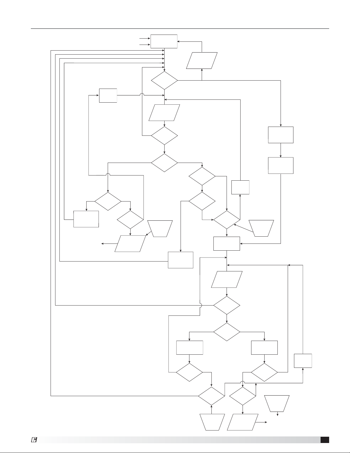
VGN Technology Control Flow Chart - Single Fan
Positive Pressure Fault
Negative Pressure Fault
Max. VFD
Monitor
Time
Above Setpoint
(more positive)
VFD
No
at Full
Speed
Yes
Yes
BMS Control
Drive
Fault Bypass
Mode
No
Static
Pressure
Valve
Static
Pressure =
Setpoint
No
Static
Pressure
Value
Drive Fault
Yes
Below Setpoint
(more negative)
Feedback at
Minimum
No
No
Minimum
Alarm
Nozzle
VFD at
Speed
Yes
Yes
Min. VFD
Monitor
Time
Fan at
Full Speed
Yes
Required
Nozzle Area
Increase
Fan Speed
Send to BMS
Controller
Time Period
Met?
Yes
Positive
Pressure
Alarm
No
Reset at
Fault CLR
Decrease
Fan Speed
Above Setpoint
(more positive)
Close
Bypass
Damper
Bypass
Feedback
= Mimimum
VDC
Yes
Yes
Yes
Time Period
Met?
Yes
BMS Control
Bypass Damper
PID
Static
Pressure
Value
Static
Pressure =
Setpoint
No
Static
Pressure
Value
No
Reset by
BMS
Below Setpoint
(more negative)
Bypass
Damper
Yes
Feedback
= Maximum
Open
Bypass
VDC
Damper
Position
Monitor
NoNo
Time
Yes
Time Period
Met?
Reset by
BMS
®
No No
Time Period
Met?
Yes
Negative
Pressure
Alarm
Reset at
Fault CLR
Send to BMS
Controller
VGN Technology
5
Page 6

General Electrical Controls Information
Fan Operation - Multiple Fans, No Staging
Set point and minimum variables
1. System will maintain a minimum of 3000 fpm velocity
(factory default) at the outlet of each fan, based on
the airflow monitoring station. Building Management
System (BMS) to monitor each fan nozzle actuator
feedback and keep fan speed above the minimum
required set point to maintain velocity.
2. Each fan to run at BMS defined operation for
fan on or off, and event timing, as required per
system airflow requirements. BMS is also required
to control fan speed for all fans. Bypass damper
mode reference will be determined by the following
scenario listed:
A. All fans in system running at minimum. Minimum
flow condition.
a. BMS will control fan speed and monitor nozzle
feedback as required to maintain system set point.
b. Decreased flow condition from minimum speed.
When the speed is equal to the minimum specific
fan speed and nozzle feedback is at minimum for a
set time period (user-defined), the BMS will begin to
modulate the bypass damper(s) open to assist with
pressure control.
Increased flow condition from minimum speed. If
the bypass damper(s) are at full closed for a set
time period (user-defined), the BMS will increase
fan speed and the fan control will increase the
nozzle area as required to assist with pressure
control.
c. The PID sequence to be programmed at the BMS
for the bypass damper(s) operation. The BMS to
provide fan enable and VFD speed reference.
B. Normal operation. Fan operation normal system
flow.
a. Flow requirement for system within reach of fan
operation. Fans operating will float together from
minimum speed to maximum speed to keep set
point.
b. If any of the fans run in the surge area for a set
time period, the BMS will need to add the bypass
damper(s).
c. The PID sequence to be programmed at the BMS
for the bypass damper(s) operation. The BMS to
provide fan enable and VFD speed reference.
Definition of typical operation modes:
Mode #1: Unoccupied. Defined as no one inside the
lab(s), all lab hoods are closed.
1. Fan(s) will operate at BMS required speed and nozzle
will modulate as necessary to achieve the required
velocity out the fan(s). BMS to monitor nozzle
actuator feedback for each fan and keep fan speed
above the minimum required to maintain velocity.
2. Sure-Aire will measure airflow of the fan. VFD or the
nozzle controller for each fan will report this value to
BMS.
3. Duct pressure control, by the BMS, will modulate
bypass damper(s) as required.
Note: Follow bypass damper(s) operation
depending on number of fans running.
4. VFD speed, duct pressure control and the bypass
damper(s) operation is provided by the BMS system.
Mode #2: Occupied; no lab hoods being used.
Defined as people entering the lab(s), no work being
done at the hoods.
1. Fan(s) will operate at BMS required speed and nozzle
will modulate as necessary to achieve the required
velocity out the fan(s). BMS to monitor nozzle
actuator feedback for each fan and keep fan speed
above the minimum required to maintain velocity.
2. Sure-Aire will measure airflow of the fan. VFD or the
nozzle controller will report this value to BMS.
3. Duct pressure control, by the BMS, will modulate
bypass damper(s) as required.
Note: Follow bypass damper(s) operation
depending on number of fans.
4. VFD speed, duct pressure control and the bypass
damper(s) operation is provided by the BMS system.
Mode #3: Occupied; some or all lab hoods being
used. Defined as people in the lab(s), lab hood sashes
being used.
A. Sashes opening in the lab
1. Fan(s) will operate at BMS required speed and
nozzle will modulate as necessary to achieve the
required velocity. Typical system response should
be to increase fan(s) speed and increase nozzle
open area.
2. Sure-Aire will measure airflow of the fan. VFD or the
nozzle controller for each fan will report this value
to BMS.
3. Duct pressure control, by the BMS, will modulate
bypass damper(s) as required.
Note: Follow bypass damper(s) operation
depending on number of fans running.
4. VFD speed, duct pressure control and the bypass
damper(s) operation is provided by the BMS
system.
VGN Technology
6
®
Page 7

General Electrical Controls Information
B. Sashes closing in the lab
1. Fan(s) will operate at BMS required speed and
nozzle will modulate as necessary to achieve the
required velocity. Typical system response should
be to decrease fan(s) speed and decrease nozzle
open area.
2. Sure-Aire will measure airflow of the fan. VFD or the
nozzle controller for each fan will report this value
to BMS.
3. Duct pressure control, by the BMS, will modulate
bypass damper(s) as required.
Note: Follow bypass damper(s) operation
depending on number of fans running.
4. VFD speed, duct pressure control and the bypass
damper(s) operation is provided by the BMS
system.
Mode #4: Fault Mode. Defined as safety mode;
the system has an issue and needs to default to VFD
bypass.
1. VFD failure detected, automatically or manually put
into VFD bypass if available by operator or BMS.
2. Nozzle area to increase proportional to fan airflow
which will increase as fan speed is at maximum.
3. Sure-Aire will measure airflow of the fan. VFD or the
nozzle controller for each fan will report this value to
BMS.
4. Duct pressure control will modulate bypass
damper(s) as required if system is in alarm mode.
Duct pressure control is provided and programmed
by the BMS system.
5. System manually to be reset and placed back in VFD
auto mode.
®
VGN Technology
7
Page 8
General Electrical Controls Information
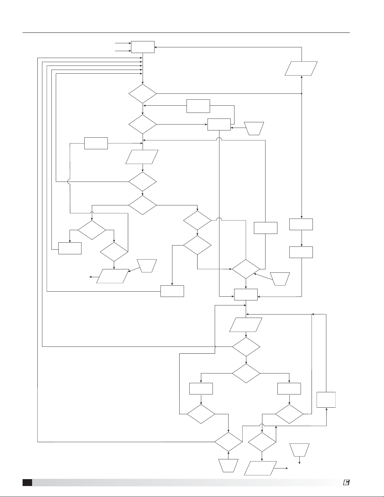
VGN Technology Control Flow Chart - Multiple Fans, No Staging
Positive Pressure Fault
Negative Pressure Fault
No
Increase
Fan(s) Speed
Send to
BMS Controller
Max. VFD
Monitor
Time
Above Setpoint
(more positive)
VFD(S) at
Full Speed
Yes
Time Period
Met?
Positive
Pressure
Alarm
Yes
Yes
BMS
Control
Drive Fault
Bypass
Mode
Fan(s) in
Stall Mode
Static Pressure
Value
Static
Pressure
= Setpoint
Static Pressure
Value
No
No
No
No
Reset at
Fault Clr
Yes
Yes
Below Setpoint
(more negative)
No
Decrease
Fan(s)
Speed
Fan Stall
Monitor Time
All Nozzle
Feedback at
Minimum
No
VFD(S)
Minimum
Speed
Yes
Yes
Time
Period
Yes
Reset by
BMS
Time Period
Time
Met?
Period
Yes
BMS Control
Bypass Damper
PID
Min. VFD
Monitor
Time
No
Reset by
BMS
Yes
Drive Fault
Alarm
Fan
Full Speed
Yes
Required
Nozzle Area
VGN Technology
8
No
Above Setpoint
(more positive)
Close
Bypass
Damper
Bypass
Feedback
= Min. VDC
Yes
Yes
Yes
Time Period
Met?
Reset by
BMS
Static Pressure
Value
Static
Pressure
= Setpoint
No
Static
Pressure
Value
Below Setpoint
(more negative)
Yes
Time Period
Met?
Yes
Negative
Pressure
Alarm
Feedback
= Max. VDC
NoNo
Open
Bypass
Damper
Bypass
BMS Controller
Reset at
Fault Clr
Send to
No
Damper
Position
Monitor
Time
®
Page 9

General Electrical Controls Information
Fan Operation - Multiple Fans, With Staging
Set point and minimum variables
1. System will maintain a minimum of 3000 fpm velocity
(factory default) at the outlet of each fan, based on
the airflow monitoring station. Building Management
System (BMS) to monitor each fan nozzle actuator
feedback and keep fan speed above the minimum
required set point to maintain velocity.
2. Each fan to run at BMS defined operation for fan
staging, on or off, and event timing, as required per
system airflow requirements. BMS is also required
to control fan speed for all fans. Bypass damper
mode reference will be determined by the following
scenario listed:
A. One fan in system running, all other fans off.
Minimum flow condition.
a. One fan in operation, BMS will control fan speed
and monitor nozzle feedback as required to
maintain system set point.
b. Decreased flow condition from minimum speed.
When the speed is equal to the minimum specific
fan speed and nozzle feedback is at minimum for a
set time period (user-defined), the BMS will begin to
modulate the bypass damper(s) open to assist with
pressure control.
Increased flow condition from minimum speed. If
the bypass damper(s) are at full closed for a set
time period (user-defined), the BMS will increase
fan speed and the fan control will increase the
nozzle area as required to assist with pressure
control.
c. If one fan is at maximum speed for a set time
period, another fan may be required to keep system
set point. Note section B for multiple fan operation.
d. The PID sequence to be programmed at the BMS
for the bypass damper(s) operation. The BMS to
provide fan enable and VFD speed reference.
B. Two or more fans running, normal operation. Fan
operation normal system flow.
a. Flow requirement for system within reach of fan
operation. Fans operating will float together from
minimum speed to maximum speed to keep set
point.
b. If all fans in operation are at maximum speed for
a set time period (user-defined) and other fans are
available, another fan can be added by the BMS as
required.
c. With additional fan added to the system, all fans in
operation will decrease and match speed of new
fan until set point is reached, then fans can float
together between minimum to maximum speed.
Note section “C” if a dead band zone is created.
d. When more than one fan is operating and all are at
the minimum speed for a set time period and the
pressure is still too negative, the BMS will need to
subtract a fan.
e. When more than one fan is in operation and any of
the fans run in the surge area for a set time period,
the BMS will need to subtract a fan or bypass
damper(s) may need to be used.
f. With the subtraction of a fan from the system, the
BMS will need to increase speed of all remaining
fans and they will float together until set point is
reached. Note section “C” if a dead band zone is
created.
g. The PID sequence to be programmed at the BMS
for the bypass damper(s) operation. The BMS to
provide fan enable and VFD speed reference.
C. Dead band in system. Flow between fans cycle
on/off.
Flow requirement for system out of reach causing
undesirable fan cycling on and off. If the fans in
the system running at full speed is not enough air
and adding an additional fan and running all fans at
minimum is too much air, then the bypass damper
mode may be necessary to settle these dead band
zones.
a. The BMS notices and counts cycling of fans to
determine dead band zone. If a dead band is
determined, the BMS will begin to modulate the
bypass damper(s) open to assist with pressure
control.
b. If the bypass damper(s) are at full closed for a set
time period, the BMS will increase fan speed and
the fan control will increase the nozzle area as
required to assist with pressure control.
c. The PID sequence to be programmed at the BMS
for the bypass damper(s) operation. The BMS to
provide fan enable and VFD speed reference.
®
VGN Technology
9
Page 10

General Electrical Controls Information
Fan Operation - Multiple Fans, With Staging - continued
Definition of typical operation modes:
Mode #1: Unoccupied. Defined as no one inside the
lab(s), all lab hoods are closed.
1. Fan(s) will operate at BMS required speed and nozzle
will modulate as necessary to achieve the required
velocity out the fan(s). BMS to monitor nozzle
actuator feedback for each fan and keep fan speed
above the minimum required to maintain velocity.
2. Sure-Aire will measure airflow of the fan. VFD or the
nozzle controller for each fan will report this value to
BMS.
3. Duct pressure control, by the BMS, will modulate
bypass damper(s) as required.
Note: Follow bypass damper(s) operation
depending on number of fans running.
4. VFD speed, duct pressure control and the bypass
damper(s) operation is provided by the BMS system.
Mode #2: Occupied; no lab hoods being used.
Defined as people entering the lab(s), no work being
done at the hoods.
1. Fan(s) will operate at BMS required speed and nozzle
will modulate as necessary to achieve the required
velocity out the fan(s). BMS to monitor nozzle
actuator feedback for each fan and keep fan speed
above the minimum required to maintain velocity.
2. Sure-Aire will measure airflow of the fan. VFD or the
nozzle controller will report this value to BMS.
3. Duct pressure control, by the BMS, will modulate
bypass damper(s) as required.
Note: Follow bypass damper(s) operation
depending on number of fans.
4. VFD speed, duct pressure control and the bypass
damper(s) operation is provided by the BMS system.
Mode #3: Occupied; some or all lab hoods being
used. Defined as people in the lab(s), lab hood sashes
being used.
A. Sashes opening in the lab
1. Fan(s) will operate at BMS required speed and
nozzle will modulate as necessary to achieve the
required velocity. Typical system response should
be to increase fan speed and increase nozzle open
area. Additional fans may be added as necessary.
2. Sure-Aire will measure airflow of the fan. VFD or the
nozzle controller for each fan will report this value
to BMS.
3. Duct pressure control, by the BMS, will modulate
bypass damper(s) as required.
Note: Follow bypass damper(s) operation
depending on number of fans running.
4. VFD speed, duct pressure control and the bypass
damper(s) operation is provided by the BMS
system.
B. Sashes closing in the lab
1. Fan(s) will operate at BMS required speed and
nozzle will modulate as necessary to achieve the
required velocity. Typical system response should
be to decrease fan speed and decrease nozzle
open area. Removal of fans may be required as
necessary.
2. Sure-Aire will measure airflow of the fan. VFD or the
nozzle controller for each fan will report this value
to BMS.
3. Duct pressure control, by the BMS, will modulate
bypass damper(s) as required.
Note: Follow bypass damper(s) operation
depending on number of fans running.
4. VFD speed, duct pressure control and the bypass
damper(s) operation is provided by the BMS
system.
Mode #4: Fault Mode. Defined as safety mode; the
system has an issue and needs to default to VFD
bypass.
1. VFD failure detected, automatically or manually put
into VFD bypass if available by operator or BMS.
2. Nozzle area to increase proportional to fan airflow
which will increase as fan speed is at maximum.
3. Sure-Aire will measure airflow of the fan. VFD or the
nozzle controller for each fan will report this value to
BMS.
4. Duct pressure control will modulate bypass
damper(s) as required if system is in alarm mode.
Duct pressure control is provided and programmed
by the BMS system.
5. System manually to be reset and placed back in VFD
auto mode.
VGN Technology
10
®
Page 11

General Electrical Controls Information
VGN Technology Control Flow Chart - Multiple Fans, With Staging
Positive Pressure Fault
Negative Pressure Fault
No
No
Increase
Fan(s) Speed
BMS Controller
Max. VFD
Monitor Time
Above Setpoint
(more positive)
VFD(S)
Full Speed
Send to
Yes
No
Yes
Fan(s)
available to
add
Time Period
Met?
Positive
Pressure
Alarm
BMS
Control
Deadband Range
Fan On/Off
Cycling
No
Drive Fault
Bypass
Mode
No
Fan(s) in
Stall Mode
No
Static
Pressure
Value
Static
Pressure
= Setpoint
No
Static Pressure
Value
Yes
No
Yes
Reset at
Fault
Clr
Yes
Yes
Yes
Time Period
Yes
Fan Stall
Monitor Time
Below Setpoint
(more negative)
Met?
Add a
Fan
No
Time Period
Met?
All Nozzle
Feedback at
Reset by
BMS
Decrease
Fan(s)
Speed
Minimum
No
VFD(S)
Minimum
Speed
Yes
Running
Time Period
BMS Control
Bypass Damper
Pressure
No No
Reset by
BMS
Fan(s)
= 1
Yes
Met?
PID
Static
Value
Yes
Yes
Time Period
Reset by
BMS
Remove
a fan
Met?
Reset by
BMS
Yes
Time Period
Met
Yes
Reset by
BMS
Yes
Drive Fault
Alarm
Fan
Full Speed
Yes
Required
Nozzle Area
Static
Yes
Pressure
= Setpoint
Above Setpoint
(more positive)
Close
Bypass
Damper
Bypass
No
Feedback
= Min. VDC
®
Yes
Yes
Time Period
Met?
Reset by
BMS
No
Below Setpoint
Static
Pressure
Value
(more negative)
Yes
No No
Time Period
Met?
Yes
Negative
Pressure
Alarm
Open
Bypass
Damper
Bypass
Feedback
= Max. VDC
Reset at
BMS Controller
No
Fault
Clr
Send to
VGN Technology
Damper
Position
Monitor
Time
11
Page 12

Electrical Controls Information for Factory-Supplied Variable Frequency Drive
System Diagram
TO BMS CONTROL
VFD IN A NEMA 3R UL LISTED ENCLOSURE WITH
BYPASS AND INTEGRATED CONTROLLER
(SHIPPED LOOSE; FIELD MOUNTED)
COMMUNICATION WIRING
- BACNET® (STANDARD)
- ANALOG SIGNAL(S) (STANDARD)
- LONWORKS® (OPTIONAL)
DRIVE BMS COMMUNICATIONS
SYSTEM POWER WIRING
DUCT PRESSURE
NOZZLE FEEDBACK
CONTROL WIRING
CONTROL
WIRING BY GFC
EQUIPMENT BY GFC
WIRING BY OTHERS
EQUIPMENT BY OTHERS
NOTES:
STATIC PRESSURE
TRANSDUCER BOX
1/4 INCH PRESSURE TUBING
- All wiring in rigid metal conduit or flexible
metal conduit and liquid tight.
- All tubing and conduit to be UV resistant
for outdoor use.
STATIC PRESSURE PROBE
VGN NOZZLE
WITH MODULATING ACTUATOR(S)
EXHAUST FAN
VEKTOR ROOF
ALL GFC PROVIDED
CONTROL DEVICES
ARE 24V POWER
SERVICE
DISCONNECT
SWITCH
(INSTALLED BY OTHERS)
1/4 INCH PRESSURE TUBING
STATIC PRESSURE TRANSDUCER
AND TERMINAL BOX SHIPPED LOOSE
MOTOR WIRING
ISOLATION DAMPER
WITH OPEN/CLOSE ACTUATOR
ROOF LINE
EXHAUST DUCT
(MODULATING)
(CONTROLLED BY BMS)
BYPASS DAMPER ACTUATOR
VGN Technology
12
®
Page 13

Electrical Controls Information for Factory-Supplied Variable Frequency Drive
Wiring Diagram
ABB ECLIPSE DRIVE WITH VGN TECHNOLOGY
CBL#1 (BLACK)
CBL#1 (WHITE)
CBL#2 (WHITE)
CBL#2 (BLACK)
CBL#3 (ORANGE)
CBL#3 (ORANGE)
CBL#3 (BLACK)
CBL#3 (RED)
SET DIP
SWITCHES
SHIELD
ABB BYPASS MODULE
1
5
14
DIGITAL RELAY OUT
CLOSE WHEN FAN ON
16
ABB DRIVE MODULE
U I
1
ANALOG INPUT
2
SIGNAL SWITCH
SGND
AI1
SURE AIRE
AGND
AO1
VARIABLE N.
DRIVE DISCONNECT LOAD SIDE
2
1
GND
3
OUTGOING POWER - TO FAN MOTOR
T1
T2
T3
GND
TB1
Nozzle VDC
Sure-Aire VCD
Isolation Power
Manual Switch 1
Manual Switch 2
+24 Volts
+24 Volts
+24 Volts
Common
Common
Common
R1
TB2
TRANSDUCER/TERMINAL
ENCLOSURE
- AT THE FAN
TRANSDUCER 2
Power Supply +
Common
1
5
14
16
AI1
AGND
AO1
VGN PCB
FUSE
POWER SUPPLY
-+
SURE-AIRE SIGNAL
0
+24DC
+24DC
COM
+24DC
COM
COM
SURAIR
ISOPWR
NOZFB1
NOZVDC
GND
NOZFB2
GND
COMM
NOZZLE POSITION
FEEDBACK TO BMS
BMS SYSTEM
SUPPLIED BY OTHERS
BMS COMMUNICATIONS (STD)
- BACNET (STANDARD)
- LONWORKS (OPTIONAL)
REQUIRED WIRING:
-DIGITAL ON/OFF (THRU COMM)
-SPEED REFERENCE (THRU COMM)
-NOZZLE FEEDBACK (HARDWIRE)
-ALARM (THRU COMM)
-FAN FLOW (THRU COMM)
TRANSDUCER 1
-+
0
DUCT PRESSURE
SIGNAL COMPONENT
BY OTHERS
ACTUATOR 4
3
1 2
5
BYPASS DAMPER
COMPONENT
BY OTHERS
NOZZLE ACTUATOR FEEDBACK RECOMMEND 1 PER SHAFT
MAY BE MULTIPLE ACTUATORS PER NOZZLE BLADE SHAFT
FAN PRESSURE (LOW&HIGH)
ACTUATOR 1
ISOLATION DAMPER
ACTUATOR 2
NOZZLE ACTUATOR 1
FACTORY WIRING
TO SURE-AIRE CONNECTION
PLATE ON FAN
- +
5
1 2
3
FIELD WIRING
5
1 2
3
®
ACTUATOR 3,4,5
ADDITIONAL NOZZLE ACTUATORS
QTY. DEPENDENT ON UNIT SIZE
VGN Technology
13
Page 14

Electrical Controls Information for Factory-Supplied Variable Frequency Drive
Communication
The VGN Technology variable frequency drive (VFD)
has an embedded fieldbus as standard and optional
fieldbus adapter(s) that can be purchased. Greenheck
offers and supports BACnet® MS/TP as our standard
communication protocol and also LonWorks® as
an optional communication. The VFD does have
other languages available, but are not supported by
Greenheck, however, it may be supported by the VFD
manufacturer. Please contact the VFD factory support if
you have alternate communication requirements.
The following information is a guide to summarize
the set up of the VFD to a BMS system. The guide is
a general overview and it is suggested the controls
contractor and BMS group reference the VFD
manual for detailed installation and setup of the VFD
communications. It is also suggested to follow the
manufacturers recommendations for communication
cable type and maximum lead length. The
recommended cable is different for each protocol.
The following is only a general checklist and does not
specify exact parameters.
NOTE
All parameters are to be modified at the bypass
keypad, which is the lower keypad on the enclosure.
BACnet® MS/TP Protocol (standard)
Connect the communication wiring from the
appropriate VFD terminations to the BMS control
system. Reference the VFD manual for terminal
location and approved wiring type.
Apply power to the VFD.
Enable BACnet MS/TP as the desired Protocol.
Place the BACnet MS/TP channel in the reset
mode, this is required to set up all the remaining
parameters.
Define the system baud rate being used.
Define the Device object instance.
Define a unique object ID.
Confirm the communication.
Configure the device name.
Take the VFD out of reset mode.
Cycle power to the VFD to save all changes.
For a list of BMS points available for BACnet MS/TP
communication, see the manufacturer’s point listing
chart(s) in the manual.
LonWorks® Protocol (optional)
The LonWorks communication requires an optional
plug-in module that is added to the bypass module of
the VFD. The module needs to be specified at time of
ordering of the fan and control system.
It is also suggested to follow the manufacturers
recommendations for communication cable type and
maximum lead length for LonWorks. The recommended
cable is different for each protocol.
Verify mounting of plug-in module that nothing was
loosened in shipping.
Connect the communication wiring from the
appropriate VFD terminations to the BMS control
system. Reference the VFD manual for terminal
location and approved wiring type.
Apply power to the VFD.
Activate the field buss adaptor port.
Verify the HOST LED is lit to a solid green color.
Program the system enable control.
Program the bypass fault reset if required to reset
VFD from BMS.
Program the system VFD speed control.
Program the VFD fault reset if required to reset VFD
from BMS.
Cycle power to the VFD to save all changes.
For a list of BMS points available for LonWorks
communication, see the manufacturer’s point listing
chart(s) in the manual.
VGN Technology
14
®
Page 15

Electrical Controls Information for Factory-Supplied Variable Frequency Drive
Start-Up Procedure - Electrical Controls
The following start-up procedure is to be completed
in order to verify that the fan is in working order.
It does not cover the details for test and balance,
VFD programming, commissioning, or system
troubleshooting which is covered in other parts of the
Installation, Operation and Maintenance Manual.
Mechanical Component System Verification
For detailed descriptions to complete these operations,
see equipment Installation, Operation and Maintenance
Manual (IOM).
Fan assembly and installation completed.
Check all fasteners for tightness, as they may loosen
during shipping.
All pressure tubing lines installed as required.
All control enclosures and devices mounted in the
appropriate locations.
Verify fan wheel alignment.
Electrical Control Components System
Verification
For detailed descriptions to complete these operations,
see equipment Installation, Operation and Maintenance
Manual, National Electrical Code and local electrical
code.
Service feeder(s) to all controls completed.
Control wiring to all devices completed.
All field electrical connections tested and torqued.
Communication wiring to Building Management
System completed.
Electrical System Start-Up for VGN
Use appropriate electrical safety gear as required.
Make sure disconnect switch at the VFD is in the
‘OFF’ position.
Verify each power phase at the VFD disconnect is
not shorted to ground using a voltmeter.
Turn on the breaker that feeds the fan VFD.
Verify the voltage is correct from phase to phase
using a voltmeter at the VFD disconnect.
Apply power to the VFD by turning on the disconnect
switch that is interlocked to the door.
Verify that the VFD is in the ‘OFF’ mode at the VFD
keypad.
Check control voltage at drive terminals to verify the
control voltage is correct.
Turn on the service disconnect switch at the fan.
Open all lab hoods inside the building and verify duct
control is operational.
Note the fan speed at the VFD keypad; it should be
at full speed.
• Increase fan speed if required using the VFD
keypad up and down arrows.
Press the ‘HAND’ button at the VFD keypad.
• The isolation damper will start to open.
• The fan speed will start to accelerate to full
speed.
• As the fan speed increases the nozzle will open
to maintain constant velocity.
Verify fan wheel rotation. Verify it matches labeled
direction and IOM.
• If the fan wheel is rotating in the wrong direction,
turn off fan, disconnect power, and lockout main
feeder.
• Reverse two of the motor wiring leads to change
wheel direction.
Reapply power and press ‘HAND’ mode once again
at the VFD keypad.
Verify fan wheel rotation, verify it matches labeled
direction and fan Installation, Operation and
Maintenance Manual.
Use the up and down arrows at VFD keypad, change
the speed to verify nozzle reaction.
- As speed increases the nozzle will open.
- As speed decreases the nozzle will close.
®
VGN Technology
15
Page 16

Electrical Controls Information for Factory-Supplied Variable Frequency Drive
System Test and Balance for VGN
The VGN Technology control system needs to be set
up at a desired fixed fan speed and nozzle area. If the
following is not done, it will be difficult to do the test
and balance of the building as the fan will continually be
adjusting during changes in the building lab airflow.
The following steps listed are necessary to create a
stable fan system for the test and balance setup of a
building.
The fan speed can be set at a fixed speed by two
different options:
Option #1 is by selecting the bypass mode; this will put
the fan at full speed.
Option #2 is put the VFD in ‘HAND’ mode; this will
give you speed adjustment from minimum speed to full
speed.
The nozzle area can by set to a fixed position by
doing the following.
1. Minimum Nozzle Actuator Signal is adjusted by
the VFD parameter #1504 at the VFD keypad. Note
the factory default setting from Greenheck prior to
adjusting. Use the following table to record for your
reference.
2. Maximum Nozzle Actuator Signal is adjusted by
the VFD parameter #1505 at the VFD keypad. Note
the factory default setting from Greenheck prior to
adjusting. Use the following table to record for your
reference.
3. To create a fixed nozzle location, the Test and
Balance personnel can set the parameter #1504 and
#1505 to the same value within Greenheck range
and it will keep the nozzle fixed to a specific location.
For example, if the maximum value is 15 mA, do not
go over that maximum value.
By setting the value to the same number, the outlet
velocity and airflow of the fan can be set to a desired
reading for balancing the building.
Parameter & Description
Minimum Nozzle Actuator
Signal Parameter 1504
Maximum Nozzle Actuator
Signal Parameter 1505
Value
(Set at Factory)
After testing is completed, VFD parameters need to
be set back to Greenheck factory default numbers
for the nozzle to modulate. The fan can be put back
into the desired mode (off, hand, or auto).
For more information on the keypad details and how
to access the following parameters, see the VFD
manufacturer user’s guide.
New User
Set Point
Nozzle Velocity Adjustment
The VGN control system is shipped from the factory to
output an average minimum 3000 fpm nozzle velocity.
The VFD for the system will have a given cfm range that
is programmed into the parameter set. The following
parameters can be set as required if the desired velocity
is required to be higher than the factory default setting.
The following steps can be done to adjust the nozzle
velocity range of the fan.
Setting the minimum range parameter of the
system:
1. Minimum air volume range is adjusted by the VFD
parameter #1502 at the VFD keypad. The factory
default setting from Greenheck is specific to every
fan; note the parameter setting prior to changing the
value and record below for future reference.
2. To change the minimum value, follow the following
guidelines.
Example: 3,500 fpm (desired)
New VFD Reading = Current VFD Reading x
(3,500/3000)
Setting the minimum speed parameter of the
system:
1. Minimum fan speed is adjusted by the VFD
parameter #2007 at the VFD keypad. Note the
parameter setting prior to changing the value and
record below for future reference.
2. The minimum fan speed may be increase from the
factory value if a higher nozzle velocity is required.
It is not required to increase the minimum fan speed
but once the nozzle is at the minimum area the
velocity may potentially go lower than the desired
velocity. It is suggested by Greenheck however
that the value not be lower then the factory preset
minimum value set at time of shipment.
Adjust Fan RPM for velocity increase:
1. The fan may also need the pulley changed to adjust
the fan RPM. It is suggested to consult the factory to
size accordingly.
After completing the velocity changes, the fan can
be put into the desired mode (off, hand, or auto).
Parameter & Description
Minimum Range Value
Parameter 1502
Minimum Speed Value
Parameter 2007
Value
(Set at Factory)
For more information on the keypad details and how
to access the following parameters, see the VFD
manufacture user’s guide.
New User
Set Point
VGN Technology
16
®
Page 17

This page is intentionally blank.
®
VGN Technology
17
Page 18

Electrical Controls Information for Customer-Supplied Variable Frequency Drive
System Diagram
DUCT PRESSURE
TO BMS CONTROL
VFD COMMUNICATION
ANALOG SIGNAL(S)
VFD POWER WIRING
VFD PROVIDED AND
PROGRAMMED BY OTHERS
CONTROL
WIRING BY GFC
EQUIPMENT BY GFC
WIRING BY OTHERS
EQUIPMENT BY OTHERS
NOTES:
- All wiring in rigid metal conduit or flexible
metal conduit and liquid tight.
- All tubing and conduit to be UV resistant
for outdoor use.
NOZZLE CONTROLLER
VGN NOZZLE
WITH MODULATING ACTUATOR(S)
SERVICE
DISCONNECT
SWITCH
ISOLATION DAMPER WIRING
FAN RUNNING
CONTROLLER
STATUS CONTACT
POWER WIRING
TO VFD BY OTHERS
NOZZLE FEEDBACK
MOTOR WIRING
ROOF LINE
STATIC PRESSURE
TRANSDUCER BOX
EXHAUST DUCT
1/4 INCH PRESSURE TUBING
STATIC PRESSURE PROBE
VGN Technology
18
VEKTOR ROOF
EXHAUST FAN
ALL GFC PROVIDED
CONTROL DEVICES
ARE 24V POWER
ISOLATION DAMPER
(INSTALLED BY OTHERS)
STATIC PRESSURE TRANSDUCER
AND TERMINAL BOX SHIPPED LOOSE
1/4 INCH PRESSURE TUBING
(MODULATING)
(CONTROLLER BY BMS)
WITH OPEN/CLOSE ACTUATOR
BYPASS DAMPER ACTUATOR
®
Page 19

Electrical Controls Information for Customer-Supplied Variable Frequency Drive
Wiring Diagram
NOZZLE CONTROLLER
TRANSDUCER
TERMINAL
ENCLOSURE
- AT THE FAN
ID2 GND Y2 Y4 GND
NOZZLE
CONTROLLER
G GO B1 GND C1 NO1
+24V
+24V
+24V
+24V
+24V
COM
COM
COM
COM
COM
SURAIR
FNRUN
ALM
NOZVDC
CFM1
GND
GND
GND
GND
TRANSFORMERS
L1L1NNGND
GND
INCOMING POWER
120/1PH. 20 AMP CIRCUIT
ISOLATION DAMPER
ALM
CFM1
FAN RUN
CONTACT(S)
FROM VFD
BY OTHERS
MEASURE
0-10VDC
COM
MEASURE
2-10VDC
+24V
NOZFB1
NOZFB2
ISOPWRFNRUN
TRANSDUCER 1
DUCT PRESSURE
SIGNAL
COMPONENT BY
OTHERS
BMS SYSTEM
SUPPLIED BY OTHERS
BMS COMMUNICATIONS (STD)
- ANALOG SIGNAL(S)
- ON/OFF CONTACT(S)
REQUIRED WIRING:
-DIGITAL ON/OFF (HARDWIRE)
-NOZZLE FEEDBACK (HARDWIRE)
-ALARM (HARDWIRE)
-FAN FLOW (HARDWIRE)
-ISOLATION DAMPER CONTACT (HARDWIRE)
-+
0
ACTUATOR 4
1 2
BYPASS DAMPER
COMPONENT BY
OTHERS
3
5
+
-
0
TRANSDUCER 2
FAN FLOW (LOW&HIGH)
TO FAN CONNECTION PLATE
+24V
+24V
+24V
COM
COM
COM
SURAIR
ISOPWR
NOZVDC
NOZFB1
GND
NOZFB2
GND
NOZZLE POSITION
FEEDBACK TO BMS
-
+
5
1 2
3
5
1 2
3
ACTUATOR 1
ISOLATION DAMPER
ACTUATOR 2
NOZZLE (REQUIRED)
ACTUATOR 3,4,5
ADDITIONAL NOZZLE ACTUATORS
QTY. DEPENDENT ON UNIT SIZE
FACTORY WIRING
FIELD WIRING
®
VGN Technology
19
Page 20

Electrical Controls Information for Customer-Supplied Variable Frequency Drive
VGN Nozzle Controller
Controller Introduction and Tutorial
The VGN Nozzle Controller is located in the main control
panel. The controller has factory set points that can
be modified to configure the system for job specific
functions. The controller introduction and directions for
the setup screens are shown in this section.
The face of the controller has six buttons, allowing the
user to view unit conditions and alter parameters. The
controller is pre-programmed with easy to use menus.
Keypad Navigation
Escape Allows the user to exit the current menu, jumping to the Main Menu.
Up | Down
!
Ì
Alarm
Enter
Program Pressing the Program button allows the user to enter the Main Program Menu.
J GREENHECK VGN
SYSTEM SETTINGS
H FAN SIZE 36
FLOW MEASURE INLET
UNITS ENGLISH
ELEVATION 10000
OUTLET VELOCITY 3000
The arrow buttons allow the user to scroll through different screens and adjust
parameters.
Button will blink red, indicating an alarm condition. Press to review current alarms. To
review previous alarms, access the DATA LOGGER through the main menu.
A. In screens with adjustable parameters, pressing the Enter button moves the cursor
from the upper left corner of the screen to the parameter. The arrow buttons can then
be used to adjust the parameter.
B. To move to the next parameter on the same screen, press the Enter button.
C. To save the change, press the Enter button until the cursor moves back to the upper
left corner of the screen.
Example of Parameter Adjustment
The cursor always begins in the upper left corner of the display and will be
blinking. Press the button to move the cursor down for parameter adjustment.
GREENHECK VGN
SYSTEM SETTINGS
H FAN SIZE J 36
FLOW MEASURE INLET
UNITS ENGLISH
ELEVATION 10000
OUTLET VELOCITY 3000
J GREENHECK VGN
SYSTEM SETTINGS
H FAN SIZE 36
FLOW MEASURE INLET
UNITS ENGLISH
ELEVATION 10000
OUTLET VELOCITY 3000
VGN Technology
20
Once the cursor has reached the desired parameter, press the buttons to
adjust the value.
When satisfied with the adjustment, press the button to save the parameter.
When finished, make certain the cursor is in the upper left corner. If the
cursor is not in the upper left corner, the changes will not be saved. The
cursor must be in the upper left corner to enable screen advancement.
®
Page 21

Electrical Controls Information for Customer-Supplied Variable Frequency Drive
Controller Menu Screens
The nozzle controller consists of five menu screens to operate the VGN system. The following information describes
the menu screens in detail.
GREENHECK VGN
AIR FLOW
FLOW xxxxx
FLOW VDC X.X VDC
LOW SCALE 0 TO XXXXX
NOZZLE OPEN XXX %
GREENHECK VGN
SYSTEM STATUS
FAN STATUS XXX
VELOCITY XXX
FAN FLOW XXX
ALARM CONTACT XXX
The following value ranges are specific to the Air Flow menu screen.
Flow Active reading calculated by the Sure-Aire system.
English = CFM; Metric = m3/hr
Flow VDC Scaled voltage output specific to the flow scale.
0 VDC = no flow; 10 VDC = maximum flow
Flow Scale Flow range specific to VGN fan.
English = CFM; Metric = m
3
/hr.
Nozzle Open Active reading stating the % open of the VGN nozzle.
0% = nozzle closed; 100% = nozzle open
The values in this menu are not user-editable and are locked by the controller program.
The following value ranges are specific to the System Status menu screen.
Fan Status Shows the status of the fan.
On or Off
Velocity Determines if outlet velocity is acceptable per system setting.
OK or Low
Fan Flow Determines if fan flow is acceptable per required nozzle area and velocity.
OK or Low
Alarm Contact Alarm and contact closure for the following.
Alarm list:
a. Velocity is below the required preset system value.
b. Fan is shown as running but no flow is being created.
The values in this menu are not user-editable and are locked by the controller program.
GREENHECK VGN
SYSTEM SETTINGS
H FAN SIZE XX
FLOW MEASURE XXXXX
UNITS XXXXXX
ELEVATION XXXXX
OUTLET VELOCITY XXXX
The following value ranges are specific to the System Settings menu screen.
H / M / C Fan Size Factory set for system fan size. Selects the correct fan
Flow Measure Sets the location of the airflow monitor location.
Units Sets up the control screen variables for the system.
Elevation Location above sea level the system is located to set air density.
Outlet Velocity Required velocity at the VGN Nozzle outlet.
All the values in this menu can be changed by the user. Note factory settings prior to making
adjustments.
GREENHECK VGN
TEST AND BALANCE
T&B BALANCING XXX
NOZZLE % OPEN XXX
FLOW CORRECT XXXX
The following value ranges are specific to the Test and Balance menu screen.
T&B Balancing Used to start the balancing process of the system.
Nozzle % Open Gives Test and Balance personnel complete control of nozzle
Flow Correct “K” factor for Test and Balance personnel to measure and adjust
All the values in this menu can be changed by the user. Note factory settings prior to making
adjustments.
variables for the control.
Inlet or outlet condition
English or Metric
0 to 10,000 feet
3,000 to 4,000 FPM; 912 to 1216 MPM.
Yes or No.
regardless of fan flow.
0% = closed; 100% = open
airflow. Note that “K” value is not CFM, but subtracts or adds to
the flow calculation within the program.
-2000 to +2000
®
VGN Technology
21
Page 22

Electrical Controls Information for Customer-Supplied Variable Frequency Drive
GREENHECK VGN
DIAGNOSTIC
INPUT B1 XX.X
INPUT ID1 XXXXX
OUTPUT NO1 XXXXX
OUTPUT Y2 XX.X
OUTPUT Y4 XX.X
The following value ranges are specific to the Diagnostic menu screen. The menu
will tell the controls electrician who is troubleshooting the system what the status
is of each Input or Output of the controller.
Input B1 Value of B1 analog input of the controller (pressure transducer).
0 VDC to 10 VDC
Input ID1 Status of the ID1 digital input of the controller (fan status).
Open or Closed
Output NO1 Status of the NO1 digital output of the controller (alarm contact).
Open or Closed
Output Y2 Value of the Y2 analog output of the controller (nozzle actuator).
2 VDC to 10 VDC
Output Y4 Value of the Y4 analog output of the controller (BMS CFM scale).
0 VDC to 10 VDC
All of these points can be verified with a volt meter between the terminal point
specified and system common using either voltage or continuity settings on the
meter.
The values in this menu are not user-editable and are locked by the controller program.
VGN Technology
22
®
Page 23

Electrical Controls Information for Customer-Supplied Variable Frequency Drive
Communication
The VGN Nozzle Controller uses digital and analog
signal(s) that need to be wired to the BMS system. The
electrical installer can reference the “Nozzle Controller”
wiring diagram for specific hookup locations and
information.
The following is a list of the BMS points from the Nozzle
Controller when the VFD is supplied by others and not
the factory.
Nozzle Controller Enclosure
1. Digital Input – Relay contact from the customer
supplied VFD to terminals +24V and FNRUN.
2. Digital Output – Dry relay contact for system alarms
from terminals ALM and COM.
3. Analog Output – Voltage output (0 to 10VDC) for fan
flow from terminals CFM1 and COM.
NOTE: CFM scale is displayed on the “AIR FLOW”
menu and then “FLOW SCALE” line.
Transducer J-Box Enclosure
Analog Output(s) – Voltage output from nozzle actuator
feedback as 2 VDC as the minimum signal. The
maximum voltage signal varies depending on fan size
but has a maximum signal of 10VDC. The terminal
connections are at NOZFB1 (shaft 1), NOZFB2 (shaft 2),
and COM.
NOTE: The feedback is necessary to monitor for
minimum VFD speed. When the output is 2VDC (and
nozzle is at minimum area) it is necessary not to drop
fan speed further as outlet velocity will drop below
desired preset value.
®
VGN Technology
23
Page 24

Electrical Controls Information for Customer-Supplied Variable Frequency Drive
Start-Up Procedure - Electrical Controls
The following start-up procedure is to be completed
in order to verify that the fan is in working order.
It does not cover the details for test and balance,
VFD programming, commissioning, or system
troubleshooting which is covered in other parts of the
Installation, Operation and Maintenance Manual.
Mechanical Component System Verification
For detailed descriptions to complete these operations,
see equipment Installation, Operation and Maintenance
Manual (IOM).
Fan assembly and installation completed.
Check all fasteners for tightness, as they may loosen
up during shipping.
All pressure tubing lines installed as required.
All control enclosures and devices mounted in the
appropriate locations.
Verify fan wheel alignment.
Electrical Control Components System
Verification
For detailed descriptions to complete these operations,
see equipment Installation, Operation and Maintenance
Manual, National Electrical Code and local electrical
code.
Service feeder(s) to all controls completed.
Control wiring to all devices completed.
All field electrical connections tested and torqued.
Communication wiring to Building Management
System completed.
Electrical System Start-Up for Nozzle
Controller
Use appropriate electrical safety gear as required.
System VFD (customer-supplied)
Make sure disconnect switch at the VFD is in the
‘OFF’ position.
Verify each power phase at the VFD disconnect is
not shorted to ground using a voltmeter.
Turn on the breaker that feeds the fan VFD.
Verify the voltage is correct from phase to phase
using a voltmeter at the VFD disconnect.
Apply power to the VFD by turning on the disconnect
switch that is interlocked to the door.
Verify that the VFD is in the ‘OFF’ mode at the VFD
keypad.
Turn on the service disconnect switch at the fan.
Nozzle Controller (factory-supplied)
Make sure feeder breaker for the nozzle controller is
in the “OFF” position.
Verify power wiring to the high voltage 120V
terminals (L1, N) is correct and is not shorted to
ground using a voltmeter.
Turn on the breaker that feeds the nozzle controller
panel.
Check control voltage to verify it is correct using a
voltmeter. Should be 24 volt control.
Verify and adjust the system controller settings in the
“System Settings” menu as required.
System Start-Up
Open all lab hoods inside the building and verify duct
control is operational.
Increase fan speed if required using the VFD keypad
up and down arrows.
Press the ‘HAND’ button at the VFD keypad.
The isolation damper will start to open.
The fan speed will start to accelerate to the set
value.
As the fan speed increases the nozzle will open to
maintain constant velocity.
Verify fan wheel rotation. Verify it matches labeled
direction and IOM.
If the fan wheel is rotating in the wrong direction, turn
off fan, disconnect power, and lockout main feeder.
Reverse two of the motor wiring leads to change
wheel direction.
Reapply power and press ‘HAND’ mode once again
at the VFD keypad.
Verify fan wheel rotation, verify it matches labeled
direction and fan Installation, Operation and
Maintenance Manual.
Use the up and down arrows at VFD keypad, change
the speed to verify nozzle reaction.
- As speed increases the nozzle will open.
- As speed decreases the nozzle will close.
VGN Technology
24
®
Page 25

Electrical Controls Information for Customer-Supplied Variable Frequency Drive
System Test and Balance for VGN
The VGN Technology control system needs to be set
up at a desired fixed fan speed and nozzle area. If the
following is not done, it will be difficult to do the test
and balance of the building as the fan will continually be
adjusting during changes in the building lab airflow. The
following steps listed are necessary to create a stable
fan system for the test and balance setup of a building.
The following steps need to be taken to do the test and
balance of the VGN system:
1. Set the VFD fan speed parameter to a desired fixed
position for testing.
2. Locate the main system control panel and access
the system controller.
a. At the controller, page thru the menu and locate
the “Test and Balance” screen.
NOTE: See “Controller Menu” screen for more
details.
b. At the “T&B Balancing” line select “YES” to
activate manual nozzle control.
c. Set the “Nozzle % Open” line to the desired fixed
value, the nozzle will not modulate and will remain
in the fixed position.
d. Take airflow measurement(s) and determine fan
flow in the system.
e. Compare controller “Fan Flow” at the menu
screen to the measured flow value in step “D”
f. Adjust the fan flow value by adjusting the “Flow
Correct” to match the airflow that was measured.
g. If the system is now balanced, change the
following at the “Test and Balance” menu.
• T&B Balancing line = NO
• Nozzle % open = 0
Nozzle Velocity Adjustment
The VGN Nozzle Controller is shipped from the factory
to output an average 3000 fpm (912 mpm) nozzle
velocity. The velocity can be adjusted by the user to
range between 3000 to 4000 fpm (912 to 1216 mpm).
The velocity is set as default from the factory as English
but can be changed to Metric.
The following steps can be done to adjust the nozzle
velocity range of the fan.
1. Locate the main system control panel and access
the system controller.
a. At the controller, page thru the menu and locate
the “System Settings” screen.
NOTE: See “Controller Menu” screen for more
details.
b. Move down the variable list to the “Outlet
Velocity” value. Note the default is 3000 fpm
(912 mpm).
c. To change the value use the up/down arrows
and adjust the velocity to the desired value
within the system range and press the enter key
to finalize the value.
These steps conclude the Nozzle Velocity portion of the
Nozzle Controller VGN system.
®
VGN Technology
25
Page 26

General Electrical Controls Information
Troubleshooting
General
Issue Possible Cause Recommended Action
Fan is running but no
pressure is being created
in the duct.
Nozzle actuator is not
responding to fan speed
changes.
Unstable fan conditions.
Fan is not balancing
the system and keeps
changing speed.
System has a positive
pressure condition.
System has an unfavorable
negative pressure
condition.
CFM reading is low or at
zero even though fan is
operating.
Isolation damper not open.
Bypass damper maybe open. Verify bypass damper is closed.
Sure-Aire transducer not reading air flow.
No power at the nozzle actuator. Verify power and signal at the actuator.
Low cfm due to laboratory hoods being
closed.
BMS PID timing is incorrect. Increase time functions in the system.
BMS PID overlap is incorrect.
Isolation damper not open.
BMS fan control not working properly.
Duct pressure transducer failure.
Broken fan belt. Check fan belt for failure.
Bypass damper maybe open. Verify bypass damper is closed.
Access panel is missing on fan or bypass air
plenum.
Nozzle is not operating and is at minimum
area.
BMS fan control not working properly.
Duct pressure transducer failure.
Bypass damper operation. Verify bypass damper operation.
Isolation damper is not open.
Sure-Aire tubing leak or blockage. Inspect tubing and blow out tubing with air.
Sure-Aire tube lines hooked up backwards. Flip the high and low tube lines.
Sure-Aire transducer for system is bad.
Laboratory hoods are closed in the building Open all laboratory hoods and verify operation.
Check power at isolation damper and determine
if it is open.
Inspect pressure tubing to transducer and verify
voltages.
Open all laboratory hoods to verify nozzle
operation.
Create an increased dead band between PID for
fan and bypass.
Check power at isolation damper and determine
if it is open.
Check BMS control and determine if condition is
occurring at full speed and bypass is closed.
Verify power and signal at duct pressure
transducer(s).
Replace missing access panels.
Check actuator power and signal.
Check BMS control and determine if condition is
occurring at fan low speed and bypass full open.
Verify power and signal at duct pressure
transducer(s).
Check power at isolation damper and determine
if it is open.
Test voltage with meter for 24V and output
signal.
VGN Factory-Supplied VFD
Issue Possible Cause Recommended Action
Fault on either keypad
display.
VFD is not communicating
to the BMS system.
Multiple.
Multiple. Consult VFD manufacturer communication guide.
Consult VFD manufacturer fault guide for
solution.
VGN Nozzle Controller Customer-Supplied VFD
Issue Possible Cause Recommended Action
Fan speed is too low. Not creating enough
airflow. Speed up fan.
Airflow not present. Check flow station and
components.
Alarm contact on nozzle
controller is “Active”
Velocity is below the required preset value
Fan is shown as running, but no flow is being
created.
General System Failure Mode
If the 2-10 VCD signal is lost from the controls and the 24V power is still present, the nozzle actuators will move to the minimum
area position.
If the 24V power is lost from the controls but the 2-10VCD signal is still present, the nozzle actuators will stay in place at the
moment when 24V power was lost.
VGN Technology
26
®
Page 27

General Electrical Controls Information
VGN Technology Maintenance
WARNING
Disconnect all electrical power and secure to the
“OFF” position prior to inspection or servicing.
Failure to comply with this safety precaution could
result in serious injury or death.
The following list is recommended preventive
maintenance of the controls system. All of these items
should be done before initial power up of the system
and then done on a routine maintenance schedule.
It is also recommended to follow the component
manufacturer maintenance recommendations that they
have stated in their IOM document(s).
Description Action Occurrence
Inspect System
Wire
Inspect System
Conduit
Inspect Wiring
Terminations
Inspect
Weather Proof
Gaskets
Inspect
Electrical
Enclosures
Inspect Nozzle
Moving
Components
Finally, it is recommended to follow the fan IOM for
recommended service and also routine maintenance on
the mechanical components of the remaining items in
the system.
Look for cracked, frayed,
bare wiring. Replace as
necessary
Look loose fittings and
cracked or broken down
seal tight. Replace as
necessary
Look for loose or broken
terminals. Tighten to
required torque for each or
replace as necessary.
Inspect all gaskets and
look for moisture. Replace
if necessary.
Inspect all enclosures and
look for broken hardware.
Replace as necessary
Inspect all nozzle
components. Remove any
obstructions or replace
any worn components.
Quarterly
Quarterly
Quarterly
Quarterly
Quarterly
Monthly
VGN Technology Electrical
Replacement Parts
Description Mfg.
Variable Frequency Drive
with Bypass
LonWorks
Communication Module
(optional)
Terminal Block, grey ABB 1SNK506010R0000
Terminal Block, green
ground
Terminal Block, separator ABB 1SNK505910R0000
Terminal Block, end stop ABB 1SNK900001R0000
Terminal Block, jumper
assembly
Fuse block, primary for
power supply
Fuse, primary
transformer
Power Supply
200 VAC Series
to 24 VDC
Power Supply
>300 VAC Series
to 24 VDC
Circuit Board Assembly As required Consult Factory
Pressure Transducer,
multiple range, VDC
Actuator,
2-position 24 VAC
(Isolation)
Actuator, modulating
2-10 VDC 24 VAC
(Nozzle)
Actuator, modulating
0/2-10 VDC 24 VAC
(Bypass)
Transformer, 120 VAC to
24 VAC
Controller, PCO Compact Carel PCOX000BB0
Controller terminals,
screw type
ABB Consult Factory
ABB ABBD-FLON-01-KIT
ABB 1SNK506150R0000
ABB 1SNK906303R0000
Little Fuse LTFS-LPSC002
Little Fuse LTFS-CCMR03.5
Lutze 722803
Lutze 722803
Mamac 275-R4-VDC2
As required Consult Factory
Belimo GMB-24-SR
As required Consult factory
Functional
Devices
Carel PCOXCON0B0
Manufacturer
Part Number
TR40VA0001
®
VGN Technology
27
Page 28

Our Commitment
As a result of our commitment to continuous improvement, Greenheck reserves the right to change specifications
without notice.
Specific Greenheck product warranties are located on greenheck.com within the product area tabs and in the
Library under Warranties.
Greenheck VGN Technology catalog provides additional
information describing the equipment, fan performance,
available accessories, and specification data.
®
Phone: 715.359.6171 • Fax: 715.355.2399 • Parts: 800.355.5354 • E-mail: gfcinfo@greenheck.com • Website: www.greenheck.com
476072 • VGN Technology Electrical Controls, Rev. 3, December 2014 Copyright 2014 © Greenheck Fan Corporation
28
AMCA Publication 410-96, Safety Practices for Users and
Installers of Industrial and Commercial Fans, provides
additional safety information. This publication can be
obtained from AMCA International, Inc. at www.amca.org.
 Loading...