

Page 1
Document 479653
!
!
!
!
Generation 2
®
Constant Pressure/Air Flow Control
Installation, Operation and Maintenance Manual
Please read and save these instructions for future reference. Read carefully before attempting to assemble, install,
operate or maintain the product described. Protect yourself and others by observing all safety information. Failure
to comply with instructions could result in personal injury and/or property damage!
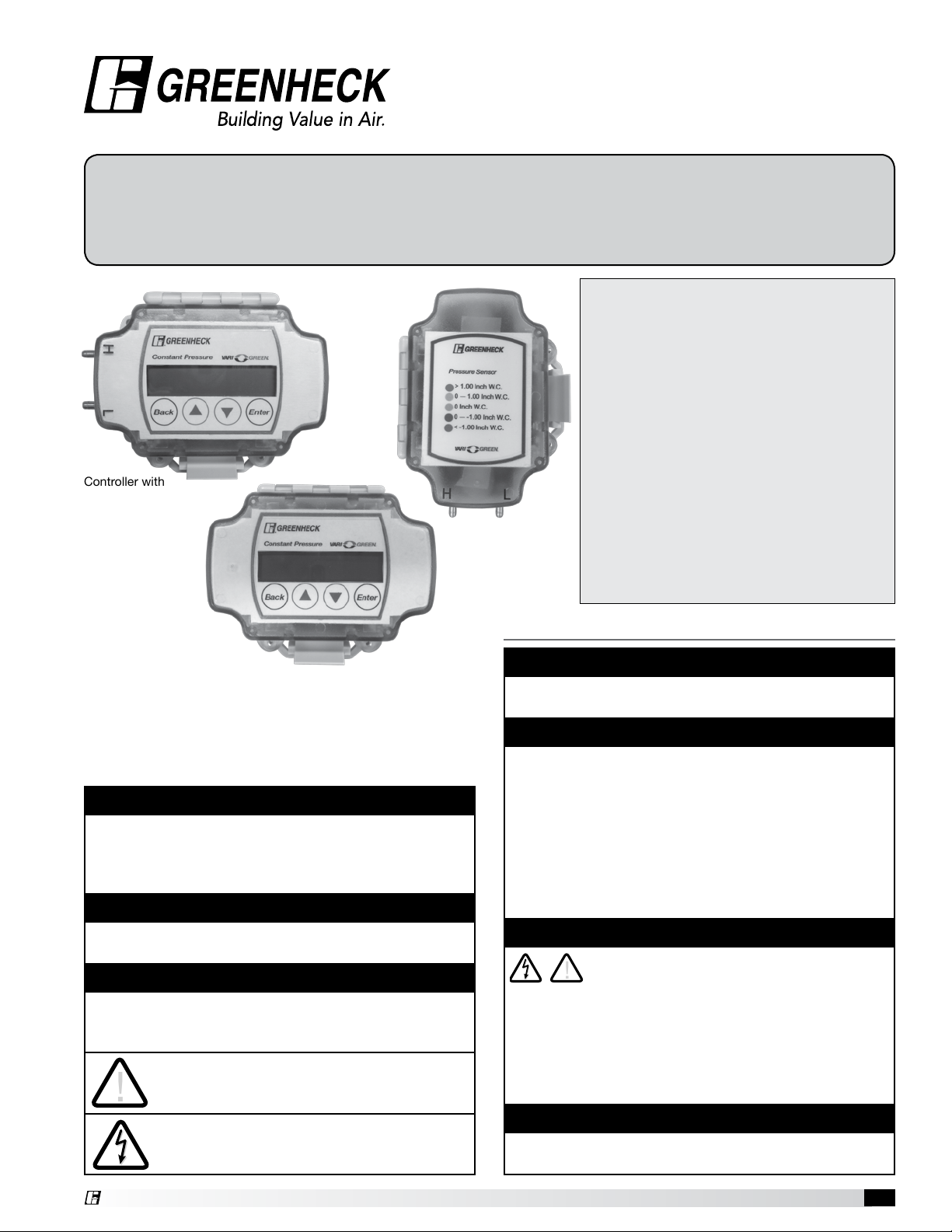
Remote
Transducer
Controller with
Integral Transducer
Controller with
Remote Transducer
Precautions and Warnings
To prevent injury and property damage, follow these
instructions. Failure to adhere to installation/operation
procedures and all applicable codes may result in
hazards as indicated by warning codes outlined below:
DANGER
Indicates an imminently hazardous situation which,
if not avoided, will result in death or serious injury.
This signal word is to limited to the most extreme
situations.
WARNING
Indicates a potentially hazardous situation which, if
not avoided, could result in death or serious injury.
CAUTION
Indicates a potentially hazardous situation which, if
not avoided, may result in minor or moderate injury. It
may also be used to alert against unsafe practices.
This is the safety alert symbol. Read and
follow instructions carefully to avoid a
dangerous situation.
This symbol alerts the user to the presence
of “dangerous voltage” inside the product
that might cause harm or electrical shock.
Table of Contents
Constant Pressure Control .................. 2
Installation ........................................... 2
General Operation .......................... 3 - 5
Initial Setup Menu Structure ................ 6
Setpoint Edit Menu Parameters .......... 7
Initial Setup Menu Parameters ............ 8
Wiring Diagrams Overview ............. 9-10
Part Number Table ............................. 10
Air Density Correction Factors .......... 11
Specifications .................................... 11
Assembly Part Numbers .................... 11
Mounting Hole Pattern ...................... 11
Safety Instructions
DANGER
Equipment can start automatically. Lockout/tagout
before servicing.
CAUTION
As with all electrical products, read manual
thoroughly. Only qualified, expert personnel should
perform maintenance and installation. Contact the
nearest authorized service facility for examination,
repair, or adjustment. Do not disassemble or repair
unit unless described in this manual; death or
injury to electrical shock or fire hazard may result.
Specifications and manual data subject to change.
Consult factory for additional information.
DANGER
HAZARDOUS VOLTAGE
• Disconnect and lock out all power before installing
or servicing equipment.
• This equipment may require locking out multiple
power sources prior to service.
• Install and wire in accordance with all applicable
local and national electrical and construction codes.
WARNING
FAILURE TO FOLLOW THESE INSTRUCTIONS
MAY RESULT IN DEATH OR SERIOUS INJURY.
Constant Pressure Control 1
Page 2
Constant Pressure Control
The Greenheck Constant Pressure Control is designed
to maintain a constant level of static pressure or airflow
by automatically adjusting the speed of a fan or position
of damper. The Constant Pressure Control output is
compatible with the Vari-Green® Motor, many variable
frequency drives (VFDs), or dampers with modulating
actuators.
The Constant Pressure Control is available with duct
or room mounted probes for static pressure control,
as well as a pitot tube or Greenheck’s AMS (Airflow
Monitoring Station) for maintaining airflow. Common
applications include:
• Multi-story
• Variable volume exhaust systems serving bathrooms
• Residential kitchen hoods or clothes dryers
• Room pressurization and filtered supply/exhaust
where constant airflow is required as the filters
become dirty
Receiving
Upon receiving the control, check to ensure all items
are accounted for by referencing the delivery receipt or
packing list. Inspect each crate or carton for shipping
damage before accepting delivery. Alert the carrier
of any damage detected. The customer will make
notification of damage (or shortage of items) on the
delivery receipt and all copies of the bill of lading which
is countersigned by the delivering carrier. If damaged,
immediately contact your Greenheck Representative.
Any physical damage to the unit after acceptance is not
the responsibility of Greenheck Fan Corporation.
Unpacking
Verify that all required parts and the correct quantity of
each item have been received. If any items are missing,
report shortages to your local representative to arrange
for obtaining missing parts.
Storage
Controls are protected against damage during
shipment. If the control cannot be installed and
operated immediately, precautions need to be taken
to prevent deterioration of the control during storage.
The user assumes responsibility of the control and any
accessories while in storage. The manufacturer will
not be responsible for damage during storage. These
suggestions are provided solely as a convenience to the
user.
Indoor - The ideal environment for the storage of control
is indoors, above grade, in a low humidity atmosphere
which is sealed to prevent the entry of blowing dust,
rain or snow. Temperatures should be evenly maintained
between 30° to 110°F (-1° to 43°C). Wide temperature
swings may cause condensation and “sweating” of
metal parts. All accessories must be stored indoors in a
clean, dry atmosphere.
Removing from Storage
As controls are removed from storage to be installed
in their final location, they should be protected and
maintained in a similar fashion until the control goes into
operation.
Installation
Parts Needed
• Control voltage wiring – 18-20ga recommended
• Pressure tubing – 1/4 inch (6mm)
• Fasteners for mounting
• Conduit fittings (1/2 inch (13mm) NPSM)
Note: Mounting hole pattern for controller and
transducer on pg. 11.
Controller – Integral Pressure Transducer
The controller with integral pressure transducer is a
NEMA-4 rated enclosure. Mount the controller in a
location where it can be accessed for programming and
status viewing. The controller should be mounted in an
environment where the temperature remains between
45° and 80° F. (7° and 27°C). This temperature range
is due to the temperature compensation range of the
integral pressure transducer. If the controller needs to
be mounted in a location that will routinely exceed this
range, the controller that accepts a remote transducer
should be used.
The controller should be mounted with the hinge of the
door on top. Keep in mind wiring and tubing lengths
when selecting a location.
Controller – Remote Pressure Transducer
The controller with remote pressure transducer is used
for applications where the controller must be mounted
in areas where the temperature may exceed the
compensation range of the pressure transducer.
Both the controller and remote pressure transducer are
in a NEMA-4 rated enclosure. The pressure transducer
should be mounted in an environment where the
temperature remains between 45° and 80°F
(7° and 27°C)
Maximum Recommended Distances
Tubing Wiring
Probe to Transducer 100 feet (30.5m) N/A
Transducer to Controller N/A 200 feet (61m)
Controller to Fan/Motor/VFD N/A 100 feet (30.5m)
Conduit Fittings
Connections - A stepped drill bit can be used to create
openings in the conduit fittings. Take care to not
damage the components inside the housing
when drilling.
Pressure Probes
A duct static, room static, 2-piece pitot tube and AMS
are available from Greenheck. Other pressure probes
may be used as well.
Duct Static Probe (FIG. 1)
The duct static probe must be located in the duct where
Constant Pressure Control2
Page 3
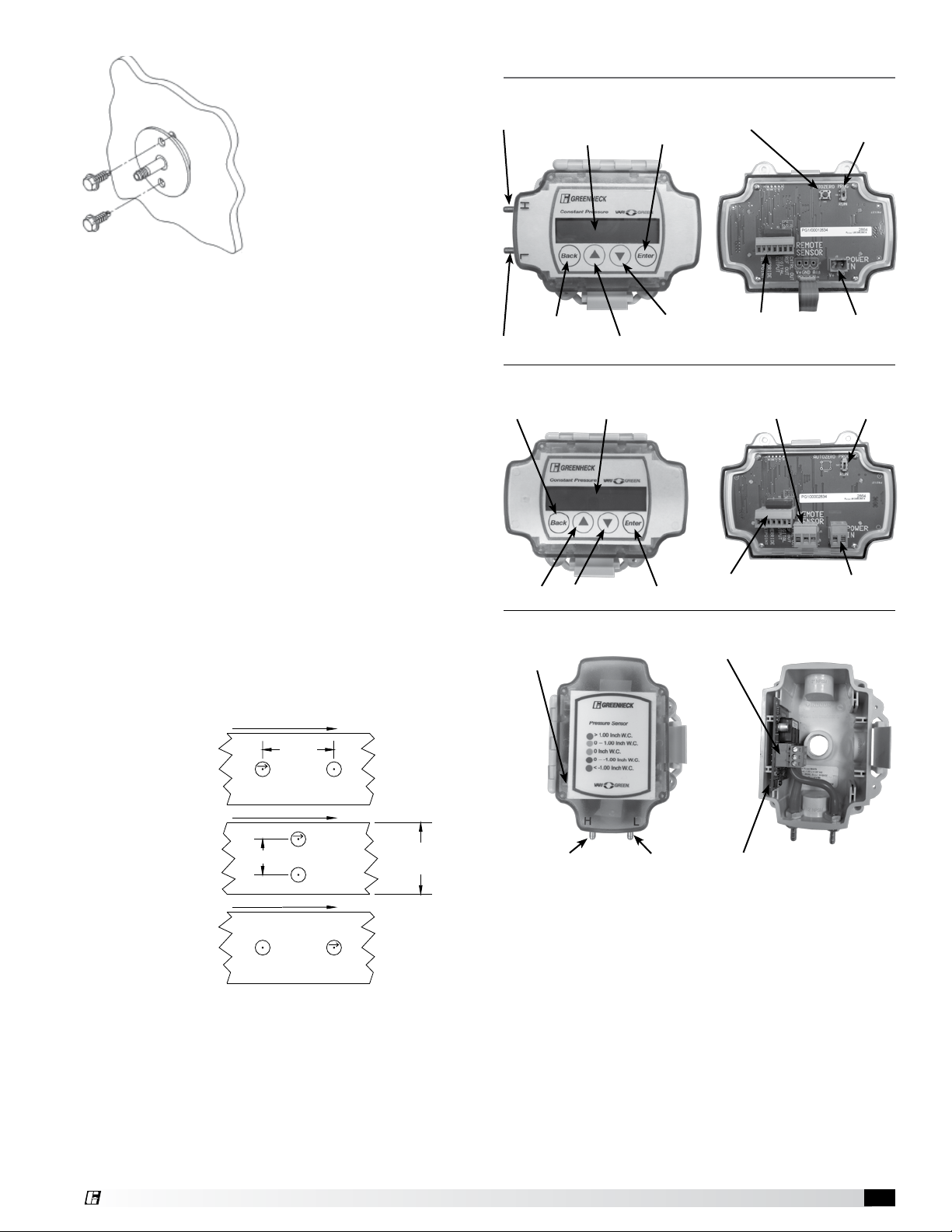
FIG. 1
you intend to control the static
pressure. It should be located
a minimum of 10’ away from
the inlet/outlet of the fan/
damper to ensure stable
operation.
The duct static probe is always
connected to the “H” port
of the control/transducer.
The “L” port is the reference
port and can remain open to
atmosphere or plumbed to another location.
General Operation
Controller with Integral Transducer
H Pressure Port
Display
Enter Button
Auto Zero Button
PROG/RUN Switch
Room Static Probe
The room static probe is used to sample the pressure in
an open space such as a room or hallway. The pressure
controlled room must be connected to the “H” port. The
“L” port is the reference port and can remain open to
atmosphere or plumbed to another location.
Alternatively, if the controller/transducer is mounted
in the space in which the pressure is to be controlled,
the “H” port can remain open and the “L” port must be
plumbed to another location for reference.
2-Piece Pitot Tube
The 2-piece pitot tube consists of a total pressure (PT)
probe and a static pressure (PS) probe. These probes
should be mounted in a straight section of ductwork
located away from elbows or transitions. The total
pressure probe can be identified by a 45deg. cut at the
end and the arrow identifying airflow direction on the
mounting flange.
Examples for mounting the probes are shown in FIG. 2
(A, B, C).
AIR FLOW
(102-203mm)
PT S
AIR FLOW
4-8 in.
P
(A)
FIG. 2
CORRECT
Back Button
L Pressure Port
Controller with Remote Transducer
Up Arrow
Remote Transducer
Status LED
Down Arrow Enter Button
Pressure
Down Arrow
Up Arrow
DisplayBack Button
Control Wiring
Connector
Romote Transducer
Wiring Connector
Control Wiring
Connector
Wiring Connector
Power Wiring
Connector
PROG/RUN
Switch
Power Wiring
Connector
(B)
(C)
INCORRECT
CORRECT
2-4 in.
AIR FLOW
(51-102mm)
SP
PT
SP
PT
12 in.
(305mm)
OR GREATER
Connect the total pressure probe to the “H” port of the
control/transducer and the static pressure probe to the
“L” port.
AMS (Airflow Measuring Station)
The AMS should be mounted away from elbows and
transitions. Connect the “HIGH” port of the AMS to the
“H” port and the “LOW” port of the AMS to the “L” port
of the control/transducer.
H Pressure Port L Pressue Port
Auto Zero Button
Display
The 2-line multi character display is backlit and is
used to read the status of the control as well as setting
parameters during programming.
Touch Buttons
The buttons on the front of the control are touch
sensitive, similar to the touch screen of a smartphone.
Gloves must be removed to ensure it senses your finger.
In RUN mode, the arrow buttons can be used to display
different process variables. In PROG mode, the arrow,
enter and back buttons are used to navigate the menus
and set parameters. When using the arrows to set
parameters, holding the button down will increase the
scrolling speed.
Constant Pressure Control 3
Page 4
LED Status
Output: XX.X%
Flow: XXXXX CFM
Dp: X.XX in WC
Flow: XXXXXX CFM
If control mode=
Constant
Pressure
If control mode=
Constant Airflow
Vel: XXXXX FPM
Flow: XXXXXX CFM
If control mode=
Constant Airflow
A status LED exists on the control and remote pressure
transducer.
Control:
Transducer:
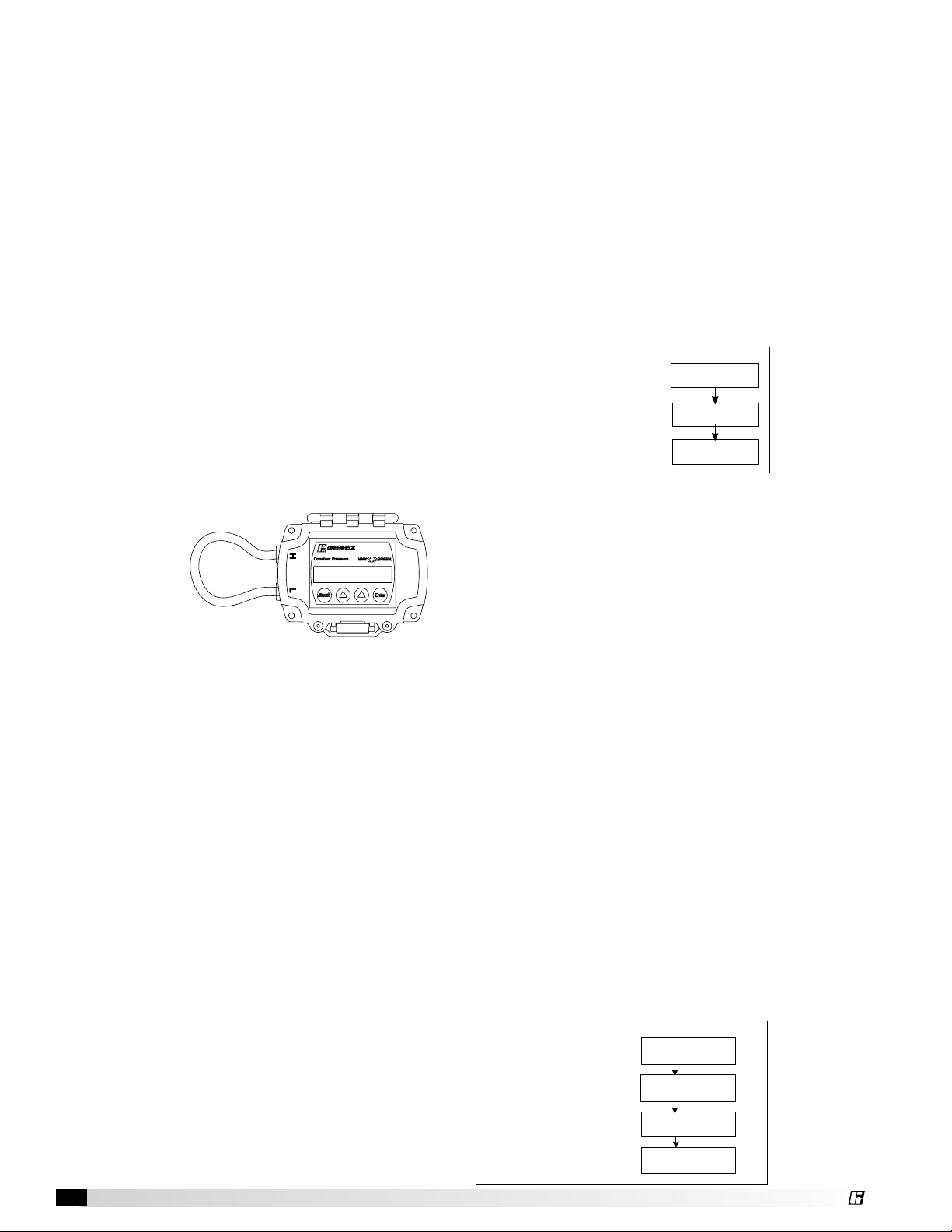
Pressure Transducer Auto Zero
The integral and remote pressure transducer includes
an auto zero function. There is an auto zero button on
the inside of the enclosure. If the controller is already
installed, remove field tubing and connect the “H” and
“L” port of the pressure transducer together with a
short piece of tubing (Fig. 3). Press the auto zero
button inside the
enclosure. When
the LED stops
flashing, remove
the tubing and
reconnect the
existing field
tubing.
Inputs/Outputs
The controller contains the following inputs/outputs:
Inputs:
Outputs:
Green = Normal Operation
Pink = Programming/manual mode
Flashing Yellow = Cutout timer is active
Solid Yellow = Cutout mode is active
Red = Override active
Red = >1.00 in.WC (>249Pa)
Green = 0 —1.00 in.WC (0-249Pa)
Yellow = 0 in.WC (0Pa)
Blue = 0 — -1.0 in.WC (249Pa)
Pink = < -1.00 in.WC (249Pa)
FIG. 3
Pressure tubing connected for auto zero
Remote Override (digital, dry contact)
• Activating this input will force the Fan Speed
output to a fixed % (adjustable)
Remote Setpoint (analog, 0-10V or 2-10V)
• A voltage signal can be sent to the control to
remotely adjust the setpoint.
Remote Transducer (analog, 0-10V)
• Not available on controller with integral
transducer.
Fan Speed (analog, 0-10V, 2-10V)
Pressure/Airflow Reference (analog, 0-10V)
• The output will send the actual pressure/airflow
value to another device, such as BMS.
Relay (digital, 0.5A rating)
• The relay output will close when the Fan Speed
output is above a set % (adjustable). Common
uses are to signal a dirty filter in airflow mode or
signal another device that the fan is being called
to run.
Constant Pressure Control4
RUN/PROG Mode
Run and Program mode are set using the selector
switch on the inside of the control. Open the control
enclosure to access the switch.
RUN Mode
This control has two major functions – constant
pressure mode and constant airflow mode.
(Set using initial set up menu. pg. 6 & 7)
Constant Pressure Mode - the control will
automatically adjust the speed of the fan to maintain a
constant static pressure in a duct or room.
The display will show the following variables
(touch the arrow buttons to change the display):
Static Pressure Reading
Output %
Pressure Setpoint
Cutout Threshold %
Cutout – The following definitions will be used to
provide clarity in the explanation of the cutout feature.
Primary Fan:
The controller is connect to this fan.
Secondary Fan:
Any fan, other than the primary fan, that
influences the pressure in the system
The cutout feature is available to turn the primary fan off
in times of no demand from the secondary fans.
There are three parameters related to the cutout
function: Cutout %, Cutout Delay Time and Return from
Cutout Pressure Setpoint.
Cutout mode is activated when the fan speed
output % is less than the cutout % setpoint. After the
Cutout Delay Time has elapsed, the control will turn the
output OFF.
A change in system pressure is needed to turn the
output back ON. This value is adjustable to prevent false
pressure fluctuations from turning the fan back on.
Constant Airflow Mode – the control will automatically
adjust the speed of a fan to maintain a constant airflow
rate in a duct.
The display will show the following variables(touch the
arrow buttons to change the display):
Airflow Reading
Output %
Differential Pressure
Reading
Velocity Reading
Airflow Setpoint
Ps: -X.XX in WC
Output: XX.X%
Ps: -X.XX in WC
Set: -0.10 in WC
Ps: -X.XX in WC
Cutout: 20.0%
Flow: XXXXX CFM
Output: XX.X%
Flow: XXXXXX CFM
Dp: X.XX in WC
Flow: XXXXXX CFM
Vel: XXXXX FPM
Flow: XXXXX CFM
Set: XXXXX CFM
Page 5

Wiring Diagrams Overview
Note: These diagrams show connections when using a
Vari-Green® motor and transformer. Other inputs/
outputs on the control are not shown for clarity.
See Pg. 10 for more details.
Integral Transducer:
Remote Transducer:
Constant Pressure Control 5
Page 6

PROG Mode:
IF
Setpoint = Local
AND
Control Mode = Constant Pressure
IF
Setpoint = Local
AND
Control Mode = Constant Airflow
Pressure Setpnt
-0.010 in
WC
Cutout Setpoint Fan
Speed: 20.8%
30 Seconds
Cutout Delay
Airflow Setpoint
5000 CFM
IF
Setpoint = Remote
IF
Control Mode = Constant PressureIFControl Mode = Constant Airflow
Setpoint Edit
Enter to
select
Set the control to program mode to
adjust initial settings and setpoints.
A manual mode also exists to
manually set the output of the
control.
Menu Structure
The structure of the program menu is
shown below. A detailed description
of the parameters follows
the diagram.
Main Menu
Control Mode
Constant Press
Setpoint
Location: Remote
Minimum Setpoint
-1.00 in WC
Maximum Setpoint
1.00 in WC
Units of Measure
Imperial
Setpoint
Location: Local
Initial Setup
Enter to Select
Units of Measure
Metric
Setpoint
Location: Remote
Minimum Setpoint
0 CFM
Maximum Setpoint
10,000 CFM
Control Mode
Constant Airflow
Setpoint
Location: Local
1-
2-
3-
4-
Initial Setup Enter to
select
Setpoint Edit Enter to
select
Factory Defaults Enter to
select
Manual Control Enter to
select
1 - Initial Setup – select this menu
to change settings related to the
application of the control, such as:
• Pressure or airflow mode
• Local or remote setpoint
• Fan inlet or outlet control
Remote Setpoint
2 to 10 VDC
Fan Control on:
Inlet
Pressure Output
0 to 10 VDC
Remote Setpoint
0 to 10 VDC
Fan Control on:
Outlet
Pressure Output
2 to 10 VDC
IF
Pressure Sensor
=
Remote
Rem Sensor Min
-1.00 in WC
Rem Sensor Max
1.00 in WC
Remote Setpoint
2 to 10 VDC
Measurement
Device: Pitot
Pitot Correction
1.00
Airflow Output
0 to 10 VDC
Pressure Sensor
SET
K = 4005
m = 0.5
IF
=
Internal
Remote Setpoint
0 to 10 VDC
Duct Area
4.00 sq ft
Measurement
Device: AMS
AMS “K” Value
2,000
AMS “m” Value
0.5000
Air Density Corr
1.00
Max Flow Output
5000 CFM
Airflow Output
2 to 10 VDC
The Setpoint Edit menu (pg. 8) is
then used to adjust the common
setpoints, such as:
• Pressure or airflow mode
• Cutout settings
• Min/max output %
• Override, digital output %
Constant Pressure Control6
Control Output
Response Time
Fast
0 to 10 VDC
Control Output
2 to 10 VDC
Startup Timer
3 seconds
Sensor Filter
0 seconds
Response Time
Medium
Save
Response Time
Slow
Page 7

1 Initial Setup Menu Parameters
Parameter Name Values Default Description
Units Imperial, Metric Imperial Units used for settings within controller
Control Mode
Setpoint Location Local, Remote Local
Min Pressure/Flow
Setpoint
Max Pressure/Flow
Setpoint
Remote Setpoint
Voltage
Fan Inlet/Outlet Inlet, Outlet Inlet
Duct Area
Measurement Device Pitot Tube, AMS Pitot Tube
AMS “K” value
AMS “m” value
Pitot Correction
Factor
Air Density Correction
Factor
Constant Pressure,
Constant Airflow
0-10V, 2-10V 0-10V
0-100 sq. ft
(0-9.29 sq. m)
0.50 to 2.00 1.00
0-5.00 1.00
Constant pressure This sets the main function of the control.
Determines where the pressure or airflow setpoint will be set.
If local, set using the setpoints menu. If remote, connect a 0-10V signal to
remotely set the setpoint.
Bottom end of pressure
transducer span
Top end of pressure
transducer span
4 sq ft
(0.37 sq. m)
This value will correspond to the minimum voltage (0 or 2V) from the
remote setpoint signal. Only available when setpoint is set to [remote].
This value will correspond to a 10V signal from the remote setpoint signal.
Only available when setpoint is set to [remote].
Change this setting based on the signal for the remote setpoint. If 0-10V,
0V refers to the minimum setpoint. If 2-10V, 2V refers to the minimum
setpoint. Only available when setpoint is set to [remote].
Set this parameter to match where the pressure probe is located in relation
to the fan the control is controlling. Only available in [pressure] mode.
Input the area of the duct where the pitot tube is located. If using an AMS,
input the area from the AMS label. Only available in [airflow] mode.
Select the measurement probe type being used. Only available in [airflow]
mode.
When AMS is used, set to “K” value on AMS label.
Only available in [airflow] mode.
When AMS is used, set to “m” value on AMS label.
Only available in [airflow] mode.
Corrects the airflow measurement for the airflow device being used.
Adjust the value if using a pitot tube by others. Only available in [airflow]
mode.
Adjust this value to match the density of the air flowing through the
system. Select the value from the table on pg. 11.
Only available in [airflow] mode
Max Flow Output
Pressure/Airflow
Output
Remote Sensor Min
Pressure
Remote Sensor Max
Pressure
Control output 0-10V, 2-10V 0-10V
Startup Timer 1-30 Seconds 3 Seconds
Sensor Filter 0-10 Seconds 0
Response Time
0-100,000 CFM
0-m3/hr 169,901
0-10V, 2-10V 0-10V This sets the span of the reference output.
Fast, Medium,
Slow
500 CFM
8495 m3/hr
-1.00 in. WC (-249Pa)
1.00 in. WC (249Pa)
Fast
Sets the top of the span for the reference output in [airflow] mode. Adjust
this setting to give more resolution to the remote airflow reading.
Set this value to the minimum pressure value of the remote pressure
transducer. Only available with remote pressure transducer model.
Set this value to the minimum pressure value of the remote pressure
transducer. Only available with remote pressure transducer model.
This value will change the span of the control output.
Vari-Green motors use 0-10V.
The control output will be set to the minimum value at startup for this
amount of time.
Adjust this value if the pressure reading is unstable.
Increasing the value increases the stability of the pressure reading.
This value adjusts the response time of the controller.
Set to Medium or Slow if the fan is unstable/oscillating.
Constant Pressure Control 7
Page 8

3 - Factory Defaults – select this to reset
Initial Setup Enter to
select
IF
Setpoint = Local
AND
Control Mode = Constant Pressure
IF
Setpoint = Local
AND
Control Mode = Constant Airflow
Pressure Setpnt
-0.010 in
WC
Cutout Setpoint Fan
Speed: 20.8%
Cut Ret Pres Set
0.010 In.
WC
30 Seconds
Cutout Delay
Airflow Setpoint
5000 CFM
20%
Minimum Output %
100%
Override Out %
100%
Maximum Output %
100%
Dig Output Set
Save
Manual Out: 50%
Ps: 0.00
in WC
IF
Setpoint = Remote
IF
Control Mode = Constant PressureIFControl Mode = Constant Airflow
Setpoint Edit
Enter to
select
Manual Control
Enter to
select
IF
Control Mode = Constant PressureIFControl Mode = Constant Airflow
Manual Out: 50%
Flow: 0
CFM
Exit
Manual Control Enter to
select
Factory Defaults Enter to
select
Setpoint Edit Enter to
select
Initial Setup Enter to
select
IF
Setpoint = Local
AND
Control Mode = Constant Pressure
IF
Setpoint = Local
AND
Control Mode = Constant Airflow
Pressure Setpnt
-0.010 in
WC
Cutout Setpoint Fan
Speed: 20.8%
Cut Ret Pres Set
0.010 In.
WC
30 Seconds
Cutout Delay
Airflow Setpoint
5000 CFM
20%
Minimum Output %
100%
Override Out %
100%
Maximum Output %
100%
Dig Output Set
IF
Setpoint = Remote
IF
Control Mode = Constant PressureIFControl Mode = Constant Airflow
Setpoint Edit
Enter to
select
Manual Control Enter to
select
Factory Defaults Enter to
select
Setpoint Edit Enter to
select
IF
Setpoint = Local
AND
Control Mode = Constant Pressure
IF
Setpoint = Local
AND
Control Mode = Constant Airflow
Pressure Setpnt
-0.010 in
WC
Cutout Setpoint Fan
Speed: 20.8%
Cut Ret Pres Set
0.010 In.
WC
30 Seconds
Cutout Delay
Airflow Setpoint
5000 CFM
20%
Minimum Output %
100%
Override Out %
100%
Maximum Output %
100%
Dig Output Set
Save
IF
Setpoint = Remote
IF
Control Mode = Constant PressureIFControl Mode = Constant Airflow
Setpoint Edit
Enter to
select
all parameters to their default values.
Factory Defaults Enter to
select
2 - Setpoint Edit Menu Structure:
The Setpoint Edit menu is then used to
adjust the common setpoints, such as:
• Pressure or airflow mode
• Cutout settings
• Min/max output %
• Override, digital output %
Restore Factory Defaults:
No
Restore Factory Defaults:
Yes
Are you sure?
YES
Exit
4 - Manual Control – select this menu to
operate the fan manually. Use the arrow
buttons to adjust speed up and down. The
display will also show the live pressure or
airflow reading (depending on setting).
Control Mode = Constant PressureIFControl Mode = Constant Airflow
Manual Out: 50%
Ps: 0.00
in WC
IF
Manual Control
select
Enter to
Exit
Manual Out: 50%
Flow: 0
CFM
Constant Pressure Control8
Page 9

2 Setpoint Edit Menu Parameters
Parameter Name Values Default Description
-1.00 to
Pressure setpoint
Airflow setpoint
Cutout %
Cutout delay time 0-300 seconds 30 seconds
Cutout return
pressure setpoint
Override
output %
Minimum
output %
Maximum
output %
Digital output
set %
*
+1.00 in WC
(-249 to +249Pa)
20 – 100% 20%
-0.250 in WC–
0.250 in WC
(-62.27 to
+ 62.27Pa)
0, 20-100% 100%
20-100% 20% Sets the minimum output value of the controller during [Run] mode.
20-100% 100% Sets the maximum output value of the controller during [Run] mode.
20-100%
-0.10 in. WC
(-24.9Pa)
inlet mode:
0.01 in. WC
(2.49Pa)
outlet mode:
-0.01 in. WC
(2.49Pa)
20% (pressure
mode) 97%
(airflow mode)
Pressure setting the control will maintain. Only available in [Pressure
Mode] and when [Local Setpoint] is selected.
Airflow setting the control will maintain. Only available in Airflow mode
and when [Local Setpoint] is selected.
When the output value falls below this setting, the output will turn off
after the delay time has elapsed. This is used to turn the primary fan
off in times of no demand. Only available in [Pressure mode].
The output value must be below the cutout threshold for this amount
of time before the fan will turn off.
Only available in [Pressure mode].
This is the threshold that the secondary fan(s) output must pass for
the primary fan to turn back on while in cutout mode.
• Inlet Mode: Measured static pressure must be more positive than
the return from cutout value.
• Outlet Mode: Measured static pressure must be more negative than
the return from cutout value.
Only available in [Pressure mode].
When the digital input is closed, the fan output will be set to this value
until the digital input is opened.
The digital (relay) output will close when the fan output is above this
value. Useful as a dirty filter switch in [Constant Airflow] mode.
More Information about the cutout feature:
*
• The cutout % value is only valid for a discreet
pressure set point. If the pressure setpoint is
changed, the cutout % must be adjusted as well.
Make sure the pressure setpoint is correct before
continuing to set the cutout.
• Steps to determine cutout %:
o Verify pressure setpoint is correct and that the
entire system is in the state where it is desired
for the fan to turn off (such as no secondary fans
operating).
o While viewing the display of the control, make
sure that the Output % value is shown. If not,
touch the up/down arrow on the control until the
Output % value is shown.
o After the pressure has stabilized at the setpoint
(usually 2-3 mins), take note of the Output %.
The value will fluctuate slightly, a mental average
is adequate.
o The recommended cutout value is 1-2 percentage
points above the value noted in the previous
step.
o EXAMPLE: With no secondary fans in the system
operating, the controller is running the primary
fan at 43.5% to maintain the pressure setpoint.
The cutout value is set at 45%. Now, any time
that the output of the control drops below 45%
(after the cutout delay time has elapsed) the fan
will turn off.
• When the Output % is less than the Cutout %, the
LED on the control will flash Yellow, signaling that
the Cutout Delay Timer has started. When the
Cutout Delay Time has elapsed, the LED will turn
solid Yellow and the Output % will show OFF.
• Troubleshooting:
o If the fan will not turn off when desired, the
cutout value is set too low.
o If the fan turns off when it is not desired, the
cutout value is set too high.
o If the fan turns off as desired, but does not turn
back on when desired:
- The cutout return pressure setpoint can be
adjusted up or down to match the system
needs.
- A pressure change must be present. If there
is nothing upstream/downstream of the
fan that will force a pressure change in the
system then the fan will not come back on
and the cutout feature should not be used.
Constant Pressure Control 9
Page 10

Note: Wiring diagrams show detail of all inputs/outputs
available.
PRESSURE CONTROL DETAIL
12-32 VDC POWER INPUT
18-28 VAC
Part Number Table
Indiv.
Part No.
Description Photo
POWER
CONTROL OUT
REF OUT
DIGITAL
OUTPUT
OVERRIDE
REMOTE SET
PRESSURE CONTROL DETAIL, REMOTE TRANSDUCER
POWER
IN
POINT
IN
GND
V+
0-10 VDC, FAN RPM
0-10 VDC, PRESSURE/FLOW REF
RELAY OUTPUT
NORMALLY
OPEN INPUT
0-10 VDC, SET POINT
12-32 VDC POWER INPUT
18-28 VAC
0-10 VDC, FAN RPM
385604
385605
385606
Controller
with Integral
Transducer
(+/- 1”)
Controller
for Remote
Transducer
Remote
Transducer
(+/- 1”)
REMOTE
TRANDUCER
CONTROL OUT
REF OUT
DIGITAL
OUTPUT
OVERRIDE
REMOTE SET
POINT
0-10 VDC FROM REMOTE TRANSDUCER
POWER TO REMOTE TRANSDUCER
0-10 VDC, PRESSURE/FLOW REF
RELAY OUTPUT
NORMALLY
OPEN INPUT
0-10 VDC, SET POINT
474748
474770
475106
Duct Static
Pressure
Probe
Room Static
Pressure
Probe
Duct Total
Pressure
Probe
Constant Pressure Control10
Page 11

Duct Air
Temp
°F
(Deg. C)
0 500 1000 1500 2000 2500 3000 3500 4000 4500 5000 5500 6000
(0) (152.4) (304.8) (457.2) (609.6) (762) (914.4) (1066.8) (1219.2) (1371.6) (1524) (1676.4) (1828.8)
Air Density Correction Factors
Elevation
Dimensions in feet and (meters)
-40 (-40) 0.79 0.81 0.82 0.84 0.85 0.87 0.88 0.9 0.92 0.93 0.95 0.97 0.99
-20 (-29) 0.83 0.85 0.86 0.88 0.89 0.91 0.93 0.94 0.96 0.98 0.99 1.02 1.04
0 (-18) 0.87 0.88 0.9 0.92 0.93 0.95 0.97 0.99 1 1.02 1.04 1.06 1.08
20 (-7) 0.91 0.92 0.94 0.96 0.97 0.99 1.01 1.03 1.05 1.07 1.08 1.11 1.13
40 (4) 0.94 0.96 0.98 1 1.01 1.03 1.05 1.07 1.09 1.11 1.13 1.16 1.18
70 (21) 1 1.02 1.04 1.06 1.08 1.1 1.12 1.14 1.16 1.18 1.2 1.22 1.25
80 (27) 1.02 1.04 1.06 1.08 1.1 1.12 1.14 1.16 1.18 1.2 1.22 1.25 1.27
100 (38) 1.06 1.08 1.1 1.12 1.14 1.16 1.18 1.2 1.22 1.25 1.27 1.29 1.32
120 (49) 1.09 1.11 1.13 1.16 1.18 1.2 1.22 1.24 1.27 1.29 1.31 1.34 1.37
140 (60) 1.13 1.15 1.17 1.2 1.22 1.24 1.26 1.29 1.31 1.34 1.36 1.39 1.41
160 (71) 1.17 1.19 1.21 1.24 1.26 1.28 1.31 1.33 1.35 1.38 1.4 1.43 1.46
180 (82) 1.21 1.23 1.25 1.28 1.3 1.32 1.35 1.37 1.4 1.42 1.45 1.48 1.51
200 (93) 1.25 1.27 1.29 1.32 1.34 1.36 1.39 1.42 1.44 1.47 1.49 1.53 1.55
Specifications
Input Power: Current Usage:
12-32VDC, 18-28VAC 100 mA Max
Output: LCD Display:
0-10VDC
(PID Output)
0-10VDC
(Pressure or Flow)
N.O. Digital (configurable)
Input: Airflow (CFM) (M
Override (Dry Contact) Mounting:
Setpoint Range:
-1.00" to +1.00" WC
(+/-249Pa)
0-10,000 CFM
(16.990 m
3
/hr)
Accuracy: Enclosure Rating:
+/- 1.0% FS @ 80F IP66, NEMA-4
Temperature
Compensation Range:
45 to 80ºF (7 to 26ºC) -13 to 175ºF (-25 to 79ºC)
Port Connection:
1/4 inch (6mm)Tubing
(1/8 to 3/16 inch ID)
(3 to 5mm ID)
Burst Pressure:
1.5psi (either port)
(10.342Pa)
Units:
Imperial Metric
Length In. / ft. mm / m
Flow CFM m
Pressure In. WC Pa
Velocity FPM m/hr
Pressure, CFM,
Output %
Control Modes:
Pressure
(Direct and Rev. Acting)
3
/hr)
Four Ext. holes for
#10 Screws
Enclosure Material:
UV-Resistant Polycarbonate,
UL94V-0
Environmental
Operating Range:
0-95% RH
non-condensing
3
/hr
Assembly Part Numbers
Description Assembly P/n Includes
Controller w/ Integral Transducer,
1 Duct Static Tap
Controller w/ Integral Transducer,
1 Room Static Tap
Controller w/ Integral Transducer,
2 Room Static Taps
Controller w/ Integral Transducer,
1 Duct Static and 1 Duct Total Tap
Controller, Remote Transducer,
1 Duct Static Tap
Controller, Remote Transducer,
1 Room Static Tap
Controller, Remote Transducer,
2 Room Static Taps
Controller, Remote Transducer,
1 Duct Static and 1 Duct Total Tap
872982 385604, 474748
872983 385604, 474770
872984 385604, 474770 (2)
872985
872986
872987
872988
872989
385604, 474748,
475106
385605, 385606,
474748
385605, 385606,
474770
385605, 385606,
474770 (2)
385605, 385606,
474748, 475106
Controller, Remote Transducer 872990 385605, 385606
Mounting Hole Pattern
41⁄16 in.
(103mm)
2 in.
(51mm)
7
⁄16 in.
1-
(37mm)
2-7⁄8 in.
(53mm)
Ø 7⁄8 in.
(22mm)
Note:
Four (4) #10 screws recommended with 5⁄32 in. (4mm)
pilot holes.
Constant Pressure Control 11
Page 12

Our Commitment
As a result of our commitment to continuous improvement, Greenheck reserves the right to change specifications
without notice.
Specific Greenheck product warranties are located on greenheck.com within the product area tabs and in the
Library under Warranties.
®
Phone: 715.359.6171 • Fax: 715.355.2399 • Parts: 800.355.5354 • E-mail: gfcinfo@greenheck.com • Website: www.greenheck.com
479653 • Constant Pressure Control, January 2015 Copyright 2015 © Greenheck Fan Corporation12
 Loading...