

Page 1
Document 476251
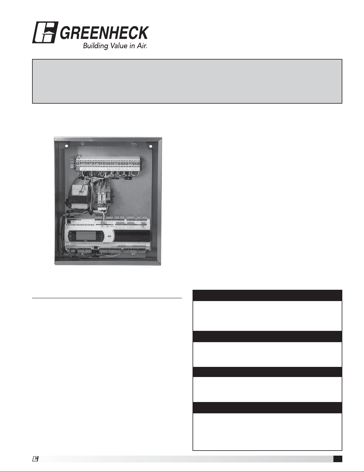
Vari-Flow Air Management System
®
Installation, Operation and Maintenance Manual
Please read and save these instructions for future reference. Read carefully before attempting to assemble,
install, operate or maintain the product described. Protect yourself and others by observing all safety
information. Failure to comply with instructions could result in personal injury and/or property damage!
Vari-Flow Air Management System
General Safety Information
Only qualified personnel should install this unit.
Personnel should have a clear understanding of these
instructions and should be aware of general safety
precautions. Improper installation can result in electric
shock, possible injury due to coming in contact with
moving parts, as well as other potential hazards. Other
considerations may be required if high winds or seismic
activity are present. If more information is needed,
contact a licensed professional engineer before moving
forward.
1. Follow all local electrical and safety codes, as well as
the National Electrical Code (NEC), the National Fire
Protection Agency (NFPA), where applicable. Follow
the Canadian Electrical Code (CEC) in Canada.
2. Do not allow the power cable to kink or come in
contact with oil, grease, hot surfaces, or chemicals.
Replace cord immediately if damaged.
3. Verify that the power source is compatible with the
equipment.
®
WARNING
Electrical shock hazard. Can cause equipment
damage, personal injury or death. Service must only
be performance by personal that are knowledgeable
in the operation of the equipment being controlled.
DANGER
Always disconnect power before working on or near a
unit. Lock and tag the disconnect switch or breaker to
prevent accidental power up.
CAUTION
When servicing the unit, variable frequency drives
may be hot enough to cause pain or injury. Allow
motor to cool before servicing.
CAUTION
It is the responsibility of the installer to make sure
both electrical and gas appliances shut down in
the event of a fire or in the event of a power loss to
the building when this sequence is required by the
authority having jurisdiction.
Vari-Flow Air Management System
1
Page 2
Table of Contents
Receiving and Handling
Receiving and Handling ........................2
Installation
Control Box Mounting ........................3
Resistive Temperature Detector ................3
Pneumatic Static Pressure Kit ...................4
Keypad Mounting .............................4
Touchscreen Mounting .........................5
Electrical Connections
Power for Vari-Flow Control ...................5
Power for Lights ............................5
Variable Frequency Drives (VFD) ................6
Vari-Green® Motor ..........................6
VFD Provided by Others ......................6
Make-Up Air VFD in Vari-Flow Wiring ............7
Make-Up Air VFD in Make-Up Air Wiring .........7
Auto Tempering .............................7
Fire System Microswitch ......................7
Resistive Temperature Detector(s) ..............8
Temperature Sensors ........................8
Keypad ...................................8
Touchscreen ...............................8
Remote Enable .............................8
Shunt Trip .................................9
Electric Gas Valve with Gas Reheat .............9
Spare Fire Relay Contacts ....................9
High Temperature Alarm Contacts ..............9
Airflow Proving .............................9
Wash Interface ..............................9
Vari-Flow Connection Checklist .................10
Sequence of Operation .......................11
System Optimization ..........................12
Controller Setup and Tutorial ................ 13-14
Menus
A.
B.
C.
D.
G.
H.
Keypad Navigation and Information ..............24
Touchscreen Navigation .................... 25-26
General Information .........................26
Settings ............................... 26-27
Configuration ..............................28
Information ...............................29
Troubleshooting .............................30
Maintenance Log .............................31
Our Commitment .............................32
On/Off Unit ........................15
Setpoint ..........................16
Clock/Scheduler ....................17
Input/Output .......................17
Service ........................18-21
Manufacturer ................... 21-23
Receiving
Upon receiving the product, check to make sure all
items are accounted for by referencing the bill of lading
to ensure all items were received. Notify the carrier if
any damage is noticed. The carrier will make notification
on the delivery receipt acknowledging any damage to
the product. All damage should be noted on all of the
copies of the bill of lading which is countersigned by the
delivering carrier. If damaged upon arrival, file a claim
with the carrier. Any physical damage to the unit after
acceptance is not the responsibility of the manufacturer.
Unpacking
Verify that all required parts and the correct quantity of
each item have been received. If any items are missing,
report shortages to your local representative to arrange
for obtaining missing parts.
Storage
If a kitchen fan control center must be stored prior to
installation, it must be protected from dirt and moisture.
Indoor storage is highly recommended. For outdoor
storage, cover the control package with a tarp to keep it
clean, dry, and protected from UV (ultraviolet) radiation
damage.
NOTE
Improper storage which results in damage to the unit
will void the warranty.
Handling
Make sure the equipment does not suffer any heavy
vibration or knocks.
Vari-Flow Air Management System
2
®
Page 3
Installation
Control Box Mounting
1. Locate an area with enough space to mount the
control box and fasten to the wall.
NOTE
Control Box may be factory mounted. If so, continue
to the next section.
NOTE
If the Vari-Flow system is equipped with static
pressure controls it will be located in the Vari-Flow
cabinet, therefore this control box should be mounted
in the space to be controlled. If the control box is
mounted outside of this space, please refer to the
Pneumatic Static Pressure Kit Installation Instructions.
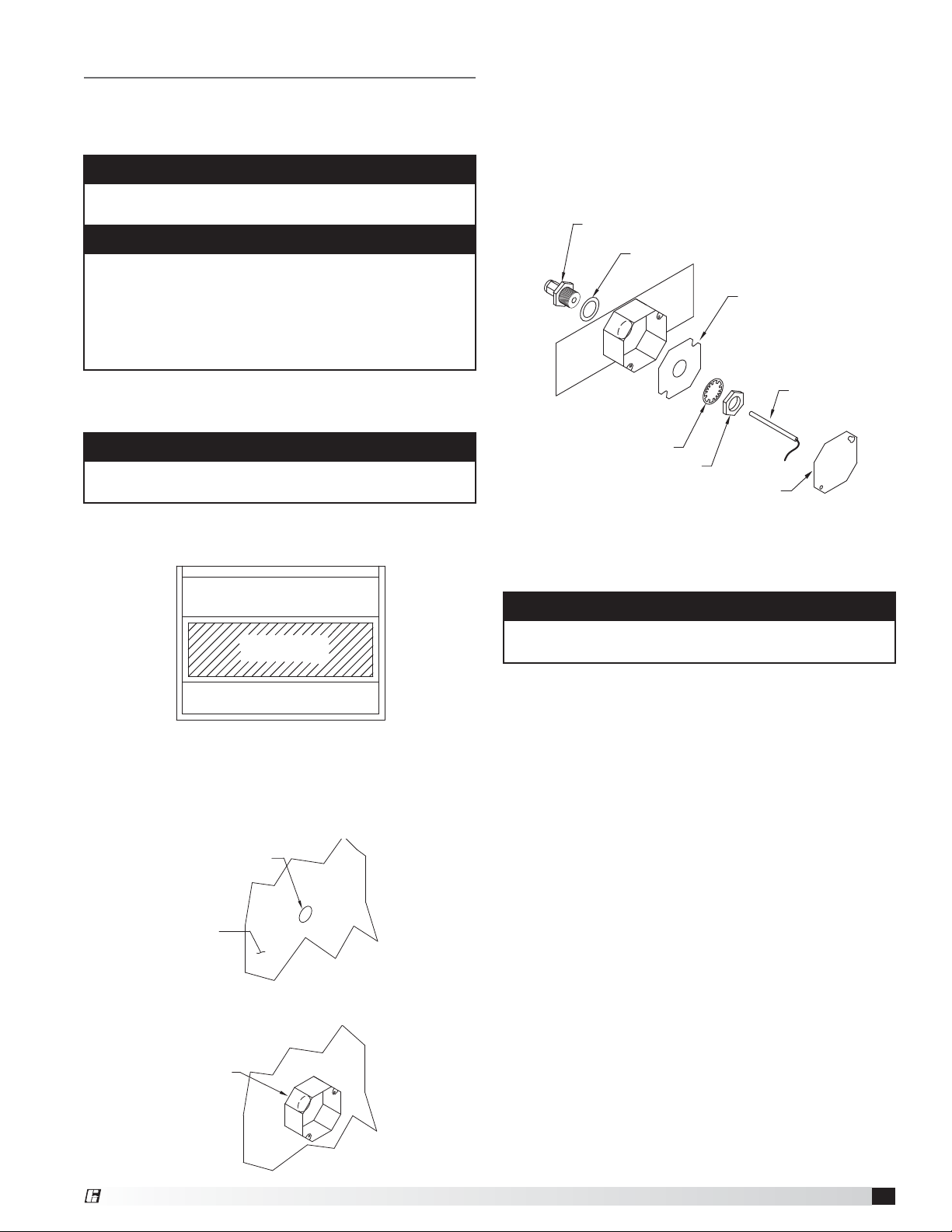
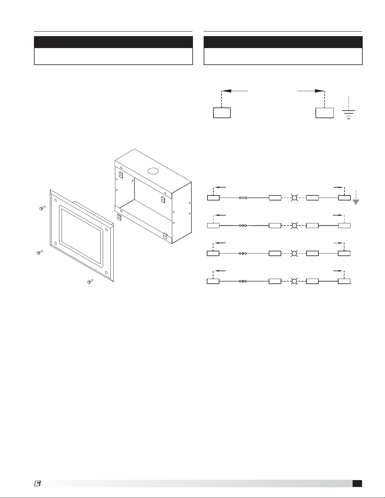
4. Insert the compression seal into the hole from
the inside of the hood making sure the gasket is
placed on the fitting before inserting it into the hole.
Place the octagon box and J-box plate provided
over the fitting on the top of the hood, keeping the
fitting centered in the box. Install the lock washer
and 1-1/2inch nut on the threaded portion of the
compression seal and tighten securely.
1/4 inch Compression Seal
Gasket
J-Box Plate
Resistive Temperature Detector(s)
(RTD) Mounting
NOTE
Resistive temperature detector(s) may be factory
installed. If so, continue to the next section.
1. Locate flat area(s) at the top interior of the hood in
front of the filters, towards the front of the hood.
Exhaust Area
Sensor Install
Cut Out Area
Supply Area (optional)
Top View of Exhaust Hood
2. Cut a 3/4-inch diameter hole into the top of the
capture tank. Make sure the resistive temperature
detector(s) will not interfere with fire system nozzles
and is not within 12 inches of light fixtures.
Temperature
Sensor
Lock Washer
Nut
Octagon Cover
5. Insert the resistive temperature detector (RTD) into
compression seal and tighten to 35 ft-lbs.
6. Place octagon cover onto J-box plate and fasten it.
NOTE
All field installation and wiring of electrical equipment
must be done to meet NEC and local codes.
.75 to .875 inch
diameter hole
Hood
Surface
3. Center the octagon extension over the hole on the
hood surface.
Octagon
Extension
®
Vari-Flow Air Management System
3
Page 4
Pneumatic Static Pressure Kit
- if equipped
NOTE
The Vari-Flow system may not be provided with the
static pressure controls, if not move onto the next
section.
1. Locate the Dwyer static pressure sensor outside of
the building in a secure location free from as many
obstructions as possible.
2. Refer to the instruction manual with the static
pressure sensor for installation and operation details.
3. Once the static pressure probe is mounted, run vinyl
tubing from the probe back to the control panel and
coil the excess tubing. Do not kink or trim the tubing.
4. If the control panel is located in the space to be
controlled, go to the next section. If the control panel
is mounted remotely from the space to be controlled,
continue to step 5.
5. Run 1/4 inch virgin poly tubing (by others) from the
sensor in the control panel to a secure location in the
space to be controlled.
Keypad Mounting
NOTE
The keypad may be factory mounted. If so, continue
to the Electrical Connections section.
1. For systems with remote controls or keypad, a 35,
75, or 150 foot RJ25 cable is supplied to connect
the keypad to the controls. The cable is plenum
rated and does not need to be run through conduit
unless required by local codes. If the keypad is to be
mounted further away than the cable that is received,
additional cable will be needed. Additional cable is
available at the lengths mentioned above.
Keypad Mounting Diagram
Vari-Flow Air Management System
4
®
Page 5
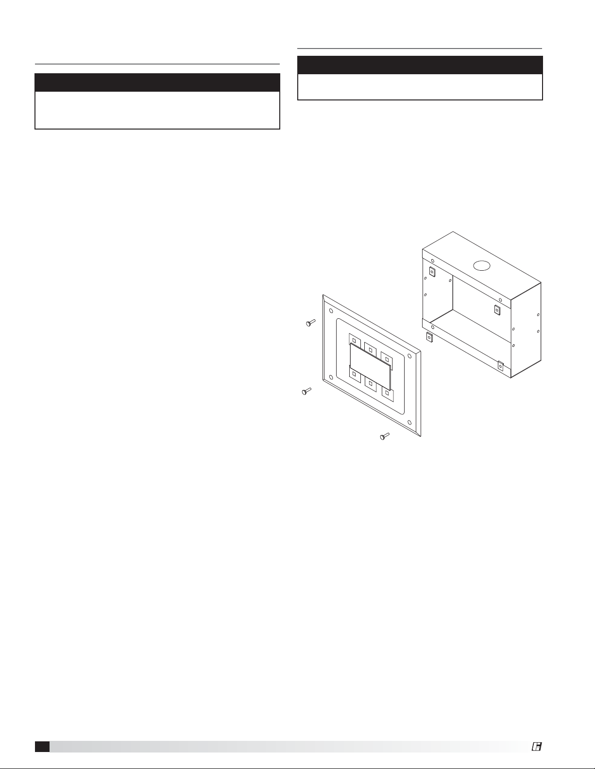
Touch Screen Mounting - if equipped
Electrical Connections
NOTE
The touch screen may be factory mounted. If so,
continue to the Electrical Connections section.
1. For systems with remote controls or touch screen,
two 35, 75, or 150 foot sets of cables are supplied to
connect the touch screen to the controls. The cables
are plenum rated and do not need to be run through
conduit unless required by local codes. If the keypad
is to be mounted further away than the cable that is
received, additional cable will be needed. Additional
cables are available at the lengths mentioned above.
Touch Screen Mounting Diagram
NOTE
All wiring of electrical equipment must be done to
meet NEC and local codes.
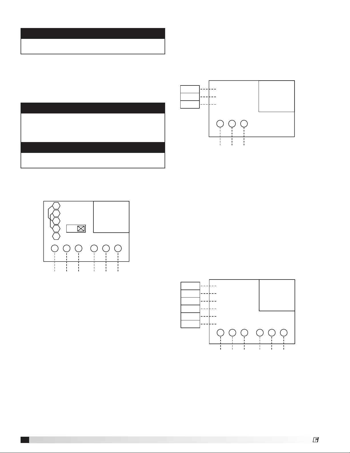
Power for Vari-Flow Cabinet
• 115 VAC, power for controls (Terminals H and N)
CONTROL INPUT:
115 VAC, 15 AMPS FROM BREAKER
H
N
Power for Lights
• 115 VAC, power for hood lights, one per light circuit
(Terminals H1, N1 | H2, N2 | H3, N3 | H4, N4)
• 115 VAC, power to lights, one per light circuit
(Terminals B1, W1 | B2, W2 | B3, W3 | B4, W4)
EACH CANOPY LIGHTING CIRCUIT MUST NOT EXCEED 15A TOTAL CURRENT
LIGHT CIRCUIT 1: 115 VAC, 15 AMPS FROM BREAKER
R1
11
H1 W1B1
BK 14GA
H2 B2 N2W2
14
HOOD LIGHT
RELAY 1
LIGHT CIRCUIT 2: 115 VAC, 15 AMPS FROM BREAKER
R2
11
14
HOOD LIGHT
RELAY 2
HOOD LIGHT(S)
HOOD LIGHT(S)
WH 14GABK 14GA BK 14GA
WH 14GABK 14GA
G
N1
G
LIGHT CIRCUIT 3: 115 VAC, 15 AMPS FROM BREAKER
R3
11
BK 14GA BK 14GA
H3 B3 N3W3
BK 14GA BK 14GA
H4 B4 N4W4
14
HOOD LIGHT
RELAY 3
LIGHT CIRCUIT 4: 115 VAC, 15 AMPS FROM BREAKER
R4
11
14
HOOD LIGHT
RELAY 4
HOOD LIGHT(S)
HOOD LIGHT(S)
WH 14GA
WH 14GA
®
Vari-Flow Air Management System
5
Page 6
Variable Frequency Drives (VFD) - if equipped
NOTE
If electrically commutated motors are being used,
VFDs will not be needed.
1. Bring power to the input of each VFD from a
dedicated power source using conduit to the
NEMA-1 enclosure on the bottom of the drive. Each
power source shall be of the same voltage as the
respective fan and of a high enough amp rating to
handle the full load amp draw of the respective fan.
NOTE
The VFD motor overload parameter (E2-01) need to
be set to the motor nameplate FLA. Refer to the Quick
Start Guide from Yaskawa (pages 83-89) for setting
these parameters on the Yaskawa drive.
NOTE
Be sure to use appropriately sized wire for the full load
amp draw.
2. To avoid interference between the conductors,
separate conduit from the VFD output to the input
power of the fan must be used for each fan.
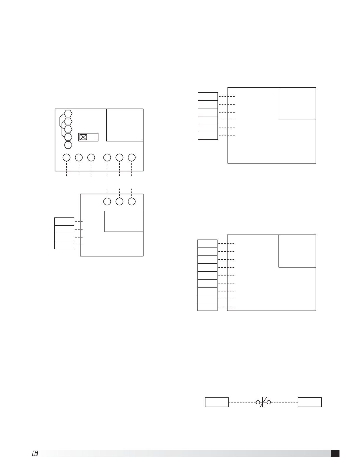
Vari-Green® Fan Wiring - if equipped
• 24 VAC from Vari-Flow to Vari-Green motor control
wire, black (Terminal E__-24)
• 0-10 VDC Speed Reference from Vari-Flow to
Vari-Green motor control wire, red (Terminal E__S+)
• Common from Vari-Flow to Vari-Green motor control
wire, white (Terminal E__S-)
E1-24
E1-S+
E1-S-
24 VAC RUN (BLACK)
SPEED REF. + (RED)
SPEED REF. - (WHITE)
G
NH
NOTE: POWER FOR THE
VARI-GREEN FAN GOES
DIRECTLY T O FAN
VFD-F1-E
MARK: VG
115/1
0.75 HP
VARI-GREEN
VARI-GREEN MOTOR
LINE
This is an example of Exhaust Fan 1 provided with a Vari-Green motor.
R+
RS+
S2
SIG
OFF
L3
L2L1
LINE
Each variable frequency drive must have the
LINE and LOAD wiring in separate conduit
VFD-F1-E
MARK: FAN MARK
VOLT/HP
MODBUS VFD
ADDRESS: X
T2T1
LOAD
T3
VFD Provided by Others, Control Wiring - if equipped
• Fault command from Vari-Flow to VFD provided by
• Run command from Vari-Flow to VFD provided by
• Speed reference from Vari-Flow to VFD provided by
MODBUS VFD
• Line power to VFD
• Load power from VFD to fan
This is an example of Exhaust Fan 1 provided with a VFD by others.
others (Terminal E__-FA, E__-FB)
others (Terminal E__-RA, E__-RB)
others (Terminal E__S+, E__S-)
E1-FA
E1-FB
E1-RA
E1-RB
E1-S+
E1-S-
NORMALLY OPEN
FAULT CONTACT
COMMON
RUN COMMAND
RUN COMMAND
SPEED REFERENCE +
SPEED REFERENCE -
L3
L2L1 T3T2T1
VFD BY OTHERS
LINE LOAD
VFD-F1-E
MARK: VFD BY
OTHERS
VOLT/PH
HP
VFD BY OTHERS
Vari-Flow Air Management System
6
®
Page 7
Make-Up Air VFD in Vari-Flow Wiring - if equipped
• 24 VAC run command from Vari-Flow to make-up air
unit (Terminals S__-42, S__-43)
• Tempering status from Vari-Flow to make-up air unit
(Terminals S__-44, S__-45)
• Line power to VFD input, bottom left of VFD
(Terminals L1, L2, L3)
• Load power from VFD output, bottom right of VFD to
make-up air disconnect (Terminals T1, T2, T3)
Make-up air unit requires separate 115 VAC control
power circuit.
THIS LAST VFD IN
R+
MODBUS LINE MUST
HAVE THE END OF
R-
LINE RESISTOR
SWITCHED ON
S+
S2
S-
ON
IG
L2L1
L3
VFD-F2-S
MARK: MUA - VFD
VAV
VOLT/PH
HP
MODBUS VFD
ADDRESS: X
T3
T2T1
MODBUS VFDMUA UNIT
Make-Up Air VFD in Make-Up Air Wiring - if equipped
• 24 VAC run command from Vari-Flow to make-up air
unit (Terminals S__-42, S__-43)
• Tempering status from Vari-Flow to make-up air unit
(Terminals S__-44, S__-45)
• 0-10 VDC speed reference from Vari-Flow to
make-up air unit (Terminals S__-46, S__-47)
Power for make-up air goes directly to make-up air unit.
S1-42
S1-43
S1-44
S1-45
S1-46
S1-47
24 VAC RUN
24 VAC COM
TEMPERING STATUS
TEMPERING STATUS
SPEED REFERENCE +
SPEED REFERENCE -
NOTE: CONTROL POWER FOR
MUA GOES DIRECTLY FROM
BREAKER PANEL TO MUA.
MARK: MUA - VFD
VFD IN MUA UNIT
(0-10 VDC)
VFD-F2-S
MUA
VOLT/PH
HP
MUA - VFD IN UNIT
S2-42
S2-43
S2-44
S2-45
LINE
RUN
24 VAC
COM
TEMPERING STATUS
TEMPERING STATUS
SEPARATE CONTROL POWER
TO UNIT REQUIRED
LOAD
DISCONNECT IN UNIT
MAKE UP AIR UNIT
CONTROL WIRING
MARK: MUA - VFD
VAV
F2-S
This is an example of Supply Fan 1 being a
make-up air with VFD in the Vari-Flow.
being a make-up air with VFD in the make-up air unit.
This is an example of Supply Fan 1
Auto Tempering - if equipped
• Auto Heat/Cool enable
(Terminals S1-R, S1-W1, S1-Y1)
S1-42
S1-43
S1-44
S1-45
S1-46
S1-47
S1-R
S1-W1
S1-Y1
24 VAC RUN
24 VAC COM
TEMPERING STATUS
TEMPERING STATUS
SPEED REFERENCE +
SPEED REFERENCE CONTROL COMMON
HEAT
COOL
NOTE: CONTROL POWER FOR
MUA GOES DIRECTLY FROM
BREAKER PANEL TO MUA.
This is an example of Supply Fan 1 with auto tempering.
MARK: MUA - VFD
VFD IN MUA UNIT
(0-10 VDC)
VFD-F2-S
VOLT/PH
MUA
HP
MUA - VFD IN UNIT
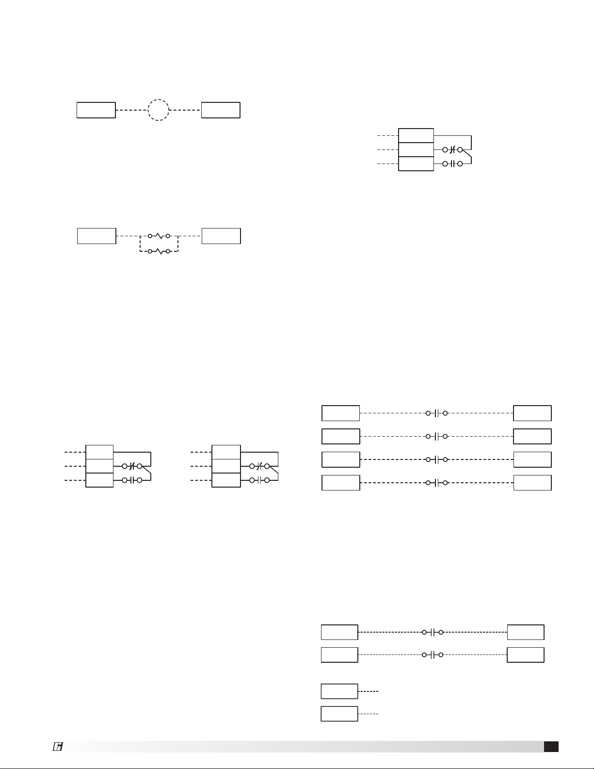
Fire System Microswitch
• Fire system microswitch common to Vari-Flow
(Terminal C1)
• Fire system microswitch normally closed contact to
Vari-Flow (Terminal NC1)
C1 NC1
®
Vari-Flow Air Management System
7
Page 8
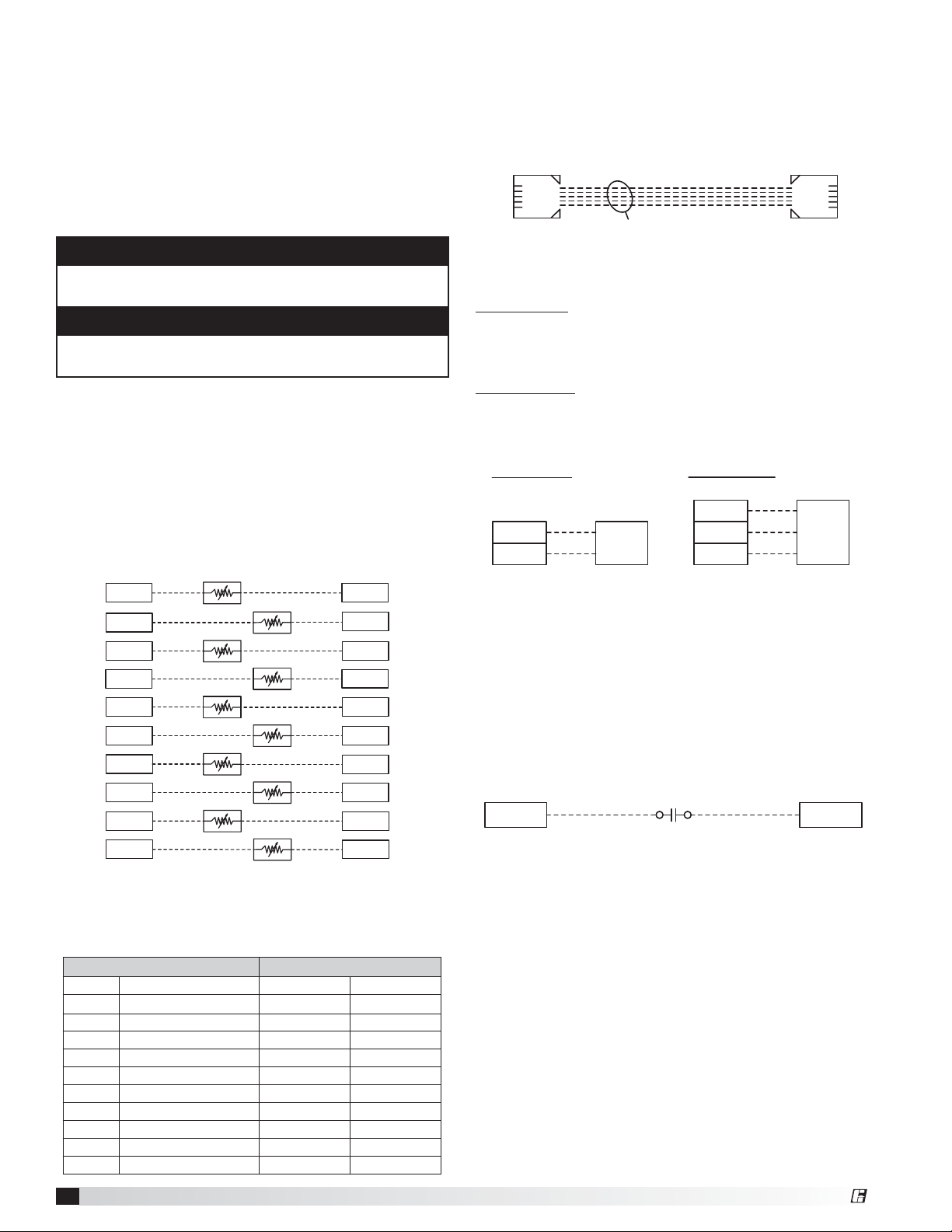
Resistive Temperature Detectors (RTD)
Wire the two leads of the sensors to be designated
terminals in the control panel as shown below. This is
determined by the number of temperature sensors on
the job (1-10 sensors). The two wires of the sensor are
not polarity sensitive. If more than one hood is being
controlled, be sure that the appropriate sensor is wired
to the appropriate terminals as depicted on the job
specific wiring diagram.
NOTE
The RTD’s should not be exposed to direct flame. The
RTD’s are rated up to 250°F
CAUTION
Exposing the sensor to direct flame may render the
sensor inoperable and will void the warranty.
Temperature Sensors* - installed in hood
• Temperature Sensor T1 to Vari-Flow
(Terminals T1-A, T1-B)
Refer to table (example below) to cross reference the
temperature sensor and the hood mark.
*Repeat based on the number of temperature sensors.
(Terminals T2-A, T2-B | T3-A, T3-B | T4-A, T4-B | T5A, T5-B | T6-A, T6-B | T7-A, T7-B | T8-A, T8-B | T9-A,
T9-B| T10-A, T10-B)
T1
T1-A T1-B
T2-A
T3-A
T4-A T4-B
T5-A T5-B
T6-A
T7-A
T8-A
T9-A
T10-A
T3
T5
T7
T9
T2
T4
T6
T8
T10
T2-B
T3-B
T6-B
T7-B
T8-B
T9-B
T10-B
Keypad - if equipped
• Connect provided cable from back of keypad to
CAREL® PCO5+ controller (Terminal J10)
CONNECT FACTORY PROVIDED RJ25 CABLE
TO J10 ON PCO5+ AND BACK OF KEYPAD
PCO5+ J10 KEYPAD
35 Foot Cable Provided
75 or 150 Foot Cable is Optional
Touchscreen - if equipped
Power Wiring
• Connect provided 2-wire cable from Vari-Flow
(Terminals 24H, 24C) to touch screen
(Terminals G, GO)
Control Wiring
• Connect provided 3-wire cable from Vari-Flow
(Terminals -, +, GND) to touch screen
(Terminals -, +, GND)
Power Wiring
24C
24H
TOUCH
SCREEN
GO
G
Control Wiring
-
+
GND
TOUCH
SCREEN
-
+
GND
Remote Enable - if used
• Connect remote enable common and normally open
from BMS to Vari-Flow (Terminals RE-1A, RE-1B)
A closed contact will turn on all fans.
An open contact will turn off all fans.
NOTE: Temperature interlock will override the remote
enable input.
RE-1A RE-1B
NOTE: The Vari-Flow job specific temperature sensor
table is found in the wiring diagram located on the VariFlow panel door. This table is an example, do not use
for your specific job.
Sensors (Field Wiring) Related Fans
Sensor Hood Mark Exhaust Fans Supply Fans
T1 Hood Mark Name 1 F1-E F11-S
T2 Hood Mark Name 2 F2-E F11-S
T3 Hood Mark Name 3 F3-E F12-S
T4 Hood Mark Name 4 F4-E F12-S
T5 Hood Mark Name 5 F5-E F12-S
T6 Hood Mark Name 6 F6-E F13-S
T7 Hood Mark Name 7 F7-E F13-S
T8 Hood Mark Name 8 F8-E F14-S
T9 Hood Mark Name 9 F9-E F14-S
T10 Hood Mark Name 10 F10-E F14-S
Vari-Flow Air Management System
8
®
Page 9
Shunt Trip - if used
• 115 VAC from Vari-Flow to shunt trip breaker coil
(provided by others) (Terminals STH, STN)
Voltage across STH, STN when in fire will be 115 VAC
Voltage across STH, STN when not in fire will be 0 VAC
STH STN
STB
Electric Gas Valve with Gas Reset - if equipped
• 115 VAC from Vari-Flow to gas solenoid
(Terminals SVH, SVN)
Voltage across SVH, SVN when in fire will be 0 VAC
Voltage across SVH, SVN when not in fire and turn on
will be 115 VAC
SVH SVN
SV1
SV2
Spare Fire Relay Contacts - if equipped
• Power to common (Terminal C3)
• Power out, normally open, closed in fire
(Terminal NO3)
• Power out, normally closed, open in fire
(Terminal NC3)
• Power to common (Terminal C4)
• Power out, normally open, closed in fire
(Terminal NO4)
• Power out, normally closed, open in fire
(Terminals NC4)
(Can be used for shunt trip, alarms, etc.)
C3
A
B
NO3
NC3
121411
R6
A
B
C4
NO4
NC4
222421
R6
High Temperature Alarm Contacts - if equipped
• Power to common (Terminal HT-C)
• Power out, normally closed, open in high
temperature alarm (Terminal HT-NC)
• Power out, normally open, closed in high
temperature alarm (Terminal HT-NO)
(Can be used for shunt trip, alarms, etc.)
HT-C
A
B
A: Closed with power at H & N and high temperature
alarm inactive, closed with no power
B: Open with power at H & N and high temperature
alarm active, open with no power
HT-NC
HT-NO
222421
R13
Airflow Proving Switch(es) (provided by others) - if
equipped
• Common and normally open from supply fan 1 air
proving switch to Vari-Flow (Terminals AP-1A, AP-1B)
• Common and normally open from supply fan 2 air
proving switch to Vari-Flow (Terminals AP-2A, AP-2B)
• Common and normally open from supply fan 3 air
proving switch to Vari-Flow (Terminals AP-3A, AP-3B)
• Common and normally open from supply fan 4 air
proving switch to Vari-Flow (Terminals AP-4A, AP-4B)
NOTE: Airflow proving switch(es) are not provided with
the Vari-Flow system.
AP-1A AP-1B
AP-2A AP-2B
AP-3A AP-3B
AP-4A AP-4B
AIR PROVING SUPPLY FAN 1
AIR PROVING SUPPLY FAN 2
AIR PROVING SUPPLY FAN 3
AIR PROVING SUPPLY FAN 4
A: Open with power at H & N and fire system armed closed on
fire or no power
B: Closed with power at H & N and fire system armed open on
fire or no power
®
Wash Interface - if equipped
• Wash input from waterwash control panel (WWCP) to
Vari-Flow (Terminals WI-1A, WI-1B)
• Wash output from Vari-Flow to Grease Grabber H
O
2
or WWCP (Terminals WO-1A, WO-1B)
• Low detergent input from Grease Grabber H
O or
2
WWCP to Vari-Flow (Terminals WD-1A, WD-1B)
WASH FAN ENABLE/DISABLE
WI-1A WI-1B
WD-1A WD-1B
WO-1A
WO-1B
WASH DETERGENT
WASH OUTPUT
Vari-Flow Air Management System
9
Page 10

Vari-Flow Connection Checklist
Power for Vari-Flow Cabinet
Connect 115 VAC power for controls (Terminals H, N)
Connect 115 VAC power for hood lights, one per light
circuit (Terminals H1, N1 | H2, N2 | H3, N3 | H4, N4)
Connect 115 VAC power to lights, one per light circuit
(Terminals B1, W1 | B2, W2 | B3, W3 | B4, W4)
Power to Variable Frequency Drives (VFD)*
Line power to VFD input, bottom left of VFD
(Terminals L1, L2, L3)
Load power from VFD output, bottom right of VFD
(Terminals T1, T2, T3)
Vari-Green® Fan Wiring* - if equipped
24 VAC from Vari-Flow to Vari-Green motor control wire,
black (Terminal E__-24)
0-10 VDC Speed Reference from Vari-Flow to Vari-Green
motor control wire, red (Terminal E__S+)
Common from Vari-Flow to Vari-Green motor control wire,
white (Terminal E__S-)
VFD Provided by Others, Control Wiring* - if equipped
Fault command from Vari-Flow to VFD provided by others
(Terminal E__-FA, E__-FB)
Run command from Vari-Flow to VFD provided by others
(Terminal E__-RA, E__RB)
Speed reference from Vari-Flow to VFD provided by others
(Terminal E__S+, E__S-)
Line power to VFD
Load power from VFD to fan
Make-Up Air VFD in Vari-Flow Wiring* - if equipped
24 VAC run command from Vari-Flow to make-up air unit
(Terminals S__-42, S__-43)
Tempering status from Vari-Flow to make-up air unit
(Terminals S__-44, S__-45)
Line power to VFD input, bottom left of VFD
(Terminals L1, L2, L3)
Load power from VFD output, bottom right of VFD to make-
up air disconnect (Terminals T1, T2, T3)
Make-Up Air VFD in Make-Up Air Wiring* - if equipped
24 VAC run command from Vari-Flow to make-up air unit
(Terminals S__-42, S__-43)
Tempering status from Vari-Flow to make-up air unit
(Terminals S__-44, S__-45)
0-10 VDC speed reference from Vari-Flow to make-up air
unit (Terminals S__-46, S__-47)
Auto Tempering - if equipped
Auto Heat/Cool enable
(Terminals S1-R, S1-W1, S1-Y1)
Fire System Microswitch
Fire system microswitch common to Vari-Flow (Terminal C1)
Fire system microswitch normally closed contact to
Vari-Flow (Terminal NC1)
* Wiring repeated based on the number of
fans of that type. This is based on the job
specific Vari-Flow wiring diagram.
Resistive Temperature Sensors* - installed in hood
Temperature Sensor T1 (Terminals T1-A, T1-B)
If more than one temperature sensor is used, wire the
following if applicable:
Temperature Sensor T2 (Terminals T2-A, T2-B)
Temperature Sensor T3 (Terminals T3-A, T3-B)
Temperature Sensor T4 (Terminals T4-A, T4-B)
Temperature Sensor T5 (Terminals T5-A, T5-B)
Temperature Sensor T6 (Terminals T6-A, T6-B)
Temperature Sensor T7 (Terminals T7-A, T7-B)
Temperature Sensor T8 (Terminals T8-A, T8-B)
Temperature Sensor T9 (Terminals T9-A, T9-B)
Temperature Sensor T10 (Terminals T10-A, T10-B)
Keypad - if equipped
Connect provided RJ25 cable from back of keypad to
CAREL® PCO5+ (Terminal J10).
Touch Screen - if equipped
Connect provided 2-wire cable from Vari-Flow
(Terminals 24H, 24C) to touch screen (Terminals G, GO)
Connect provided 3-wire cable from Vari-Flow
(Terminals -, +, GND) to touch screen (Terminals -, +, GND)
Remote Enable- if used
Connect remote enable common and normally open from
BMS to Vari-Flow (Terminals RE-1A, RE-1B)
Shunt Trip - if used
115 VAC from Vari-Flow to shunt trip breaker coil (provided
by others) (Terminals STH, STN)
Electric Gas Valve with Gas Reset - if equipped
115 VAC from Vari-Flow to gas solenoid
(Terminals SVH, SVN)
Spare Fire Relay Contacts - if equipped
Power to common (Terminal C3)
Power out, normally open, closed in fire (Terminal NO3)
Power out, normally closed, open in fire (Terminal NC3)
Power to common (Terminal C4)
Power out, normally open, closed in fire (Terminal NO4)
Power out, normally closed, open in fire (Terminal NC4)
High Temperature Alarm Contacts - if equipped
Power to common (Terminals HT-C)
Power out, normally closed, open in high temperature alarm
(Terminal HT-NC)
Power out, normally open, closed in high temperature alarm
(Terminal HT-NO)
Air Proving Switch(es) (provided by others) - if equipped
Common and normally open from supply fan 1 air proving
switch to Vari-Flow (Terminals AP-1A, AP-1B)
Common and normally open from supply fan 2 air proving
switch to Vari-Flow (Terminals AP-2A, AP-2B)
Common and normally open from supply fan 3 air proving
switch to Vari-Flow (Terminals AP-3A, AP-3B)
Common and normally open from supply fan 4 air proving
switch to Vari-Flow (Terminals AP-4A, AP-4B)
Wash Interface - if equipped
Wash input from waterwash control panel (WWCP) to
Vari-Flow (Terminals WI-1A, WI-1B)
Wash output from Vari-Flow to Grease Grabber H
O or
2
WWCP (Terminals WO-1A, WO-1B)
Low detergent input from Grease Grabber H
O or WWCP to
2
Vari-Flow (Terminals WD-1A, WD-1B)
Vari-Flow Air Management System
10
®
Page 11

Sequence of Operation
Normal Operation
1. Press the fans on/off button on the Vari-Flow keypad
or touch screen to turn the fans on (manual mode).
a. Vari-Flow will turn on all exhaust and supply fans.
b. The Vari-Flow system starts the fans at idle
speed and automatically adjusts exhaust fan
speeds between the low speed setpoint (50%
default) and high speed setpoint (100% default)
based on actual cooking loads as sensed by
the temperature sensors mounted in the hood
capture area. This is determined by the low
temperature setpoint (90°F default) and high
temperature setpoint (115°F default).
c. The Vari-Flow system adjusts the supply speed
based on a weighted average of the exhaust
fan speed. *If static pressure sensor is used for
supply airflow control it will adjust the supply
speed based on static pressure.
2. Press the fans button on the Vari-Flow keypad or
touch screen again to turn off the fans.
a. The Vari-Flow system may go into auto mode if
conditions 3.a-3.c are met.
3. Temperature interlock mode (auto mode).
a. If the temperature in the hood goes above the
temperature interlock on setpoint (115°F default)
and the fans are currently off, the Vari-Flow will
automatically turn on the associated exhaust
and/or supply fans.
b. If the temperature in the hood goes below the
temperature interlock off setpoint (90°F default)
and the fans are not currently turned on manually
the fans will turn off after the temperature
interlock off delay time setpoint (10 minute
default).
c. If the fans were turned on manually and the
user attempts to turn off the fans with the hood
temperature not meeting condition b the fan(s)
will remain on until such conditions are met.
4. With the fan(s) on via manual or auto mode, the
100% override button will force the exhaust fan(s)
that are currently on to full speed for the 100%
override off delay setpoint. The supply fan will adjust
speed the same as 1.c.
5. Pressing the 100% override button on the Vari-Flow
keypad or touch screen again will turn the 100%
override off and return the fans to the speed as
discussed in 1.b.
6. Pressing the hood lights on/off button on the VariFlow keypad or touch screen will turn on the hood
lights.
7. Pressing the hood lights on/off button on the VariFlow keypad/touch screen again will turn off the
hood lights.
Fire Operation:
1. With the fire system microswitch wired to terminal
C1 and NC1 and the fire system in a fire state, the
following will occur:
a. System fault will appear on keypad or touch
screen.
b. Vari-Flow will force the exhaust fan(s) to full
speed.
c. Vari-Flow will force the supply fan(s) off.
d. Vari-Flow will send 115 VAC signal to shunt trip
breaker coil (breaker provided by others).
e. Vari-Flow will force the lights off (if selected with
lights out in fire).
f. Vari-Flow will force the electric gas valve off (if
selected with gas valve reset option).
Fault Operation:
1. Temperature sensor fault.
a. System fault will appear on keypad or touch
screen.
b. Associated fan(s) will be turned on and forced to
full speed until fault is rectified.
2. Exhaust VFD fault.
a. System fault will appear on keypad or touch
screen.
b. All fans will be turned on and forced to full speed.
It will remain this way until the fault is rectified.
3. Supply VFD fault.
a. System fault will appear on keypad or touch
screen.
b. All fans will be turned on and forced to full
speed (for the event that if the fault clears it will
automatically run the fans at full speed). It will
remain this way until the fault is rectified.
4. Supply airflow proving fault - if equipped.
a. System fault will appear on keypad or touch
screen.
b. Exhaust fans will not turn on until supply airflow
has been proven. It will remain this way until the
fault is rectified.
5. Pressure sensor fault - if equipped.
a. System fault will appear on keypad or touch
screen.
b. Supply fan speed will automatically be controlled
via weighted average until the fault is rectified.
6. High temperature alarm - if equipped.
a. System fault will appear on keypad or touch
screen.
b. Vari-Flow will send 115 VAC signal to shunt trip
breaker coil (breaker provided by others).
c. Vari-Flow will force the electric gas valve off (if
selected with gas valve reset option).
®
Vari-Flow Air Management System
11
Page 12

System Optimization
Low Temperature Set Point (90°F default)
Record the kitchen ambient temperature ___________
Set the low temperature set point 5°F above the
ambient kitchen temperature
Setting the Low Temperature Set Point
NOTE: If the system is provided with a keypad, press
the Prg button (
menu.
1. Go to Setpoints menu.
2. Go to Exhaust Fan Setup on page 16.
3. Adjust the Low Temp Setpoint to the previously
recorded value.
High Temperature Set Point (115°F default)
1. Turn the fans on by pressing the ‘FAN’ button on the
keypad.
2. Turn on all cooking appliances and allow them to
reach normal cooking temperatures.
3. Record the temperature in the hood by looking at the
temperature in the main menu. __________
4. Set the high temperature set point 5°F below the
previously recorded temperature.
Setting the High Temperature Set Point
NOTE: If the system is provided with a keypad press
the Prg button (
menu.
1. Go to Setpoints menu.
2. Go to Exhaust Fan Setup on page 16.
3. Adjust the High Temp Setpoint to the previously
recorded value.
4. Press ESC until you reach the keypad indicators on
the LCD screen.
) for 5 seconds to enter the main
) for 5 seconds to enter the main
Vari-Flow Air Management System
12
®
Page 13

Controller Setup and Tutorial
When the user interface is a keypad, the user will need
to press the
When the user interface is a touch screen, the user
will see the main menu without having to press the
button.
Within the programmable logic controller, factory set
points can be modified to configure the system for
specific functions if necessary. All parameters are
shown in this section.
button to enter the main menu.
Keypad Navigation
Escape Allows the user to exit the current menu, jumping to the Main Menu.
Some of the menus require the user to enter a password
in order to enter the menu. The service password is
1000 and is entered by pressing the
The DDC controller is located in the unit control panel.
The face of the controller has six buttons, allowing the
user to view unit conditions and alter parameters. The
DDC controller is pre-programmed with easy to use
menus.
To change the display contrast, hold the Enter and
Escape button while pressing the up and down arrows.
A keypad also connects via the J10 port. A RJ25 cable
is needed.
A complete listing of all settings within the Controller
U1 are provided in this Installation, Operation and
Maintenance Manual.
and buttons.
Up | Down
!
Ì
Exhaust Fan 1 Setup
Temp Speed
Low: 90.0°F 50.0%
High: 115.0°F 100.0%
Exhaust Fan 1 Setup
Temp Speed
Low: 90.0°F 50.0%
High: 115.0°F 100.0%
Alarm
Enter
Program Pressing the Program button allows the user to enter the Main Program Menu.
The arrow buttons allow the user to scroll through different screens and adjust
parameters.
Button will blink red, indicating an alarm condition. Press to review current alarms. To
review previous alarms, access the DATA LOGGER through the main menu.
A. In screens with adjustable parameters, pressing the Enter button moves the cursor
from the upper left corner of the screen to the parameter. The arrow buttons can then
be used to adjust the parameter.
B. To move to the next parameter on the same screen, press the Enter button.
C. To save the change, press the Enter button until the cursor moves back to the upper
left corner of the screen.
Example of Parameter Adjustment
The cursor always begins in the upper left corner of the display and will be
blinking. Press the button to move the cursor down for parameter adjustment.
Once the cursor has reached the desired parameter, press the buttons to
adjust the value.
Exhaust Fan 1 Setup
Temp Speed
Low: 90.0°F 50.0%
High: 115.0°F 100.0%
®
When satisfied with the adjustment, press the button to save the parameter.
When finished, make certain the cursor is in the upper left corner. If the
cursor is not in the upper left corner, the changes will not be saved. The
cursor must be in the upper left corner to enable screen advancement.
Vari-Flow Air Management System
13
Page 14

Main Menu Overview
The Vari-Flow controller will revert to a default main menu loop. This loop includes several screens to view the
operating conditions of the unit. Scroll through the menu screens by using the
line border are dependent upon an optional accessory and may not always appear.
buttons. Screens with a dashed
TIME DATE UNIT##
Hood 1: ON Speed
XXX.X°F XXX.X%
*Exp: Offline
VFD: Offline
Status: UNIT ON
TIME DATE UNIT##
Supply 1: ON Speed
XXX.X% XXX.X%
*Exp: Offline
VFD: Offline
Status: UNIT ON
If an alarm occurs, the
Alarms
Press DOWN to review
current alarm(s).
Press ESC to exit.
Press ALARM to reset.
EXHAUST FAN #1 S TATU S:
The temperature on this screen displays real-time conditions from the sensors
located in the hood. The speed on this screen displays the real-time conditions of
the fan.
The “*Exp: Offline” only appears if the system is equipped with an expansion
controller, but the DDC controller sees it as off the network. The “VFD: Offline”
only appears if the DDC controller is not connected to the drive.
If there are additional exhaust fans, the display on the screen will be the same
besides the fan number.
S
UPPLY FAN # 1 STATUS. (IF EQUIPPED)
If equipped with supply fan, this screen will display the airflow percentage (left)
and the supply fan speed signal.
If there are additional supply fans the display on the screen will be the same
besides the fan number.
Example of Alarms
button will glow red on the controller and the remote display (if installed).
To view alarm, press the button once. This will display the most recent alarm.
Press the
the cause of the alarm has not been fixed. Press the buttons to view any
additional occurring alarms.
button again to reset the alarm. If the alarm cannot be cleared,
This is an example of a hood temperature sensor failure.
Hood Temperature
Sensor B01 Failure
Alarms
No active alarm
Press ENTER
to DATA LOGGER
This screen appears if there are no active alarms.
To view all saved alarms, press the
button to enter the DATA LOGGER. For
more information, see the Data Logger menu.
Type List of Possible Alarms Description Type
Exhaust VFD Fault Failure of an exhaust VFD Alarm only
Supply VFD Fault Failure of a supply VFD Alarm only
Hood Temperature Sensor Failure Failure of a hood temperature sensor Alarm only
Hood High Temperature Alarm Indicates a high hood temperature Alarm only
Pressure Sensor Failure Indicates a pressure that is out of range Alarm only
Supply Airflow Indicates a loss of airflow in the supply fan Alarm only
Fire Alarm Indicates a fire Alarm only
VFD Communication Alarm Indicates a loss of communication to the VFD failure Alarm only
BMS Communication Alarm Indicates a loss of communication to the BMS Alarm only
Vari-Flow Air Management System
14
®
Page 15

Menus
The controller is equipped with several menus to help guide users with altering program parameters. The following
menus can be accessed by pressing the
A. On/Off Unit
The On/Off Unit menu allows the user to view the detailed On/Off status of the
controller.
button. To enter the desired menu, press the
button.
On/Off Unit
Unit address: 1
Power By Display: ON
Status: UNIT ON
On/Off Exhaust
1: ON
2: ON
On/Off Light Circuits
1: ON
2: ON
3: ON
4: ON
Lights Out in Fire: ON
Status: The controller may be in following On/Off states:
a. Unit On: Unit is ON, functioning normally.
b. Off by ALARM: Unit is OFF due to an alarm. View alarms by pressing
ALARM button.
c. Off by PLAN: Unit is OFF by pLAN network.
d. Off by BMS: Unit is OFF by BMS command
e. Off by SCHEDULER: Unit is OFF by internal Clock/Scheduler.
f. Off by DIGITAL INPUT(ID4): Unit is OFF by digital input 4 (ID4).
g. Off by KEYPAD: Unit is commanded OFF by this screen.
THIS SCREEN DISPLAYS THE STATE OF THE EXHAUST FANS AND ALLOWS THE USER TO
TURN THE FAN(S) ON/OFF INDEPENDENTLY.
Exhaust: The number of fans listed is based on the number of fans for the specific
job.
THIS SCREEN DISPLAYS THE STATE OF LIGHTS AND ALLOWS THE USER TO TURN THE
LIGHT CIRCUITS ON/OFF INDEPENDENTLY.
Lights: The number of light circuits listed is based on the number of light circuits
for the specific job.
Note: If “Lights Out in Fire” is set to ON, hood lights will shut off in a fire state.
On/Off Options
Gas Valve: OFF
Wash Setup
Wash: OFF
Time: 60m
Override
Start: OFF
Full Speed: OFF
Auto Tempering
Auto Tempering: OFF
THIS SCREEN DISPLAYS THE STATE OF THE ELECTRIC GAS VALVE AND ALLOWS THE USER
TO TURN THE GAS VALVE ON/OFF. (IF EQUIPPED)
Note: In the event of a fire, the gas valve will turn off automatically. You are
required to manually turn it back on after the fire system has been reset.
THIS SCREEN DISPLAYS THE STATE OF THE WASH BUTTON AND ALLOWS THE USER TO
START A WASH.
Time: The length of time the Vari-Flow is in a wash state and will not allow the
fans to run.
THIS SCREEN DISPLAYS THE STATE OF THE FAN 100% BUTTON AND ALLOWS THE USER
TO START THE 100% OVERRIDE.
Note: When start is changed to ON it will immediately turn back to off, the full
speed status will change to ON until the override time is met or the 100% button is
pressed again. This page is used for a status of the “Fan 100” button.
THIS SCREEN DISPLAYS THE STATE OF THE AUTO TEMPERING BUTTON AND ALLOWS THE
USER TO TURN AUTO TEMPERING ON/OFF.
Auto Tempering: Enables/Disables the make-up air from automatically heating/
cooling based on the inlet air sensor.
®
Vari-Flow Air Management System
15
Page 16

B. Setpoint
The Setpoint menu allows the user to view and adjust temperature related
parameters.
Temperature Interlock
Enable: ON
Temp On: 115.0°F
Temp Off: 90.0°F
Delay Off: 600s
Exhaust Fan 1 Setup
Temp Speed
Low: 90.0°F 50.0%
High: 115.0°F 100.0%
CFM: XXXX
THIS SCREEN DISPLAYS THE CURRENT SET POINTS FOR THE TEMPERATURE INTERLOCK
FEATURE.
The user can use the default exhaust fan temperature set points or configure them
using the system optimization process. This option satisfies IMC 507.2.1.1
(Fan(s) must automatically activate when cooking operations occur.)
• Temp On Set Point: The temperature at which the fan(s) automatically turn on
based on the temperature of the associated hood. The default is 115°F and is
adjustable.
• Temp Off Set Point: The temperature at which the fan(s) automatically turn
off based on the temperature of the associated hood. It must also satisfy the
requirement of the Minimum Off Delay Set Point. The default is 90°F and is
adjustable.
• Off Delay Set Point: The amount of time the temperature must remain
below the Minimum Off Set point before the fan(s) will turn off. The default is
10minutes and is adjustable.
THIS SCREEN DISPLAYS EXHAUST FAN SETUP.
Low Temp: Temperature that the fan will start to increase in speed from the low
speed set point.
High Temp: Temperature that the fan will be at the high speed set point.
Low Speed: Minimum speed of the fan.
High Speed: Maximum speed of the fan.
Depending on the number of exhaust fans, other exhaust fan setup pages will appear.
Supply Fan 1 Setup
Design MaxSpd CFM:XXX
Min: 50.0%
Max: 100.0%
Min Tempering: 66.0%
Override
Duration: 10m
Factory Settings
Smoke Fire Stat
Exhaust Fans: 100%
High Temperature Alm
Enable: Off
Temp On: 210.0°F
Temp Off: 205.0°F
THIS SCREEN DISPLAYS THE SUPPLY FAN SETUP.
Design Max Speed: Design airflow of the supply fan.
Min: Minimum speed of the supply fan.
Max: Maximum speed of the supply fan.
Min Tempering: Minimum speed of the supply fan when it is tempering.
Depending on the number of supply fans, other supply fan setup pages will appear.
THESE PARAMETERS DICTATE THE AMOUNT TIME THE THAT THE FAN RUNS AT FULL
SPEED WHEN THE “FAN 100%” BUTTON IS PRESSED.
THIS SCREEN DISPLAYS THE SETTING FOR THE EXHAUST FANS IN THE EVENT OF A FIRE.
Once the fire inspection has been completed, this should not be changed.
THIS SCREEN DISPLAYS THE HIGH TEMPERATURE ALARM SETTINGS.
When enabled and the temperature reaches the Temp On set point the shunt trip
output will become active, forcing the electric equipment off. If there is an electric
gas valve and it is wired into the VAV system it will also turn that off. Once the
temperature is below the Temp Off set point the shunt trip output and gas valve
will return to normal state.
Remember that the shunt trip breaker will have to be manually reset as well as the
electric gas valve.
Vari-Flow Air Management System
16
®
Page 17

C. Clock/Scheduler
The Clock/Scheduler menu allows the user to view and alter the time and date.
The user can also add up to seven schedules for occupancy requirements.
Clock
Date: MM/DD/YY
Hour: 15:30
Day: Monday
Clock
DST: Enable
Transition time: 60min
Start: LAST SUNDAY
in MARCH at 2.00
End: LAST SUNDAY
in OCTOBER at 3.00
D. Input/Output
Analog Input
Temperature 1
Input B001: 95.0°F
THE CLOCK SCREEN ALLOWS THE USER TO ADJUST THE TIME AND DATE.
THIS SCREEN ALLOWS THE USER TO ADJUST DAYLIGHT SAVINGS TIME SETTINGS.
The Daylight Savings time feature can be adjusted to meet the current daylight
savings time requirements.
The Input/Output menu allows the user to quickly view the status of the controller
inputs and outputs.
To manually control I/O values, go to the Service menu > Manual management.
Similar screens appear for all controller inputs and outputs.
Your controller may not utilize all of the inputs and outputs shown. See unit wiring
diagram for your specific configuration.
Digital Input
Remote On/Off
DI 1 STATUS: Closed
Relay Output
Relay 1 STATUS: OFF
Analog Output
Output: 5.00vdc
Similar screens appear for all controller inputs and outputs.
Your controller may not utilize all of the inputs and outputs shown. See unit wiring
diagram for your specific configuration.
Similar screens appear for all controller inputs and outputs.
Your controller may not utilize all of the inputs and outputs shown. See unit wiring
diagram for your specific configuration.
Similar screens appear for all controller inputs and outputs.
Your controller may not utilize all of the inputs and outputs shown. See unit wiring
diagram for your specific configuration.
®
Vari-Flow Air Management System
17
Page 18

G. Service
The Service menu allows the user to access several sub-menus regarding controller
information, controller overrides, operating hours, BMS configuration, I/O manual
management and Probe Adjustment. The user can also change the default Service
Password (1000) by accessing the Service Settings sub-menu. By accessing the
BMS Config sub-menu, the user can adjust BMS protocol settings. (BACnet®,
LonWorks®, Modbus)
G. Service
b. Information
Information
Greenheck Fan
Code:
Ver.: 1.00 03/18/13
Manual: VARI-FLOW_IOM
Bios: 6.00 04/01/02
Boot: 4.00 04/01/02
G. Service
c. VFD Status
ENTERING THE INFORMATION SUB-MENU WILL DISPLAY INFORMATION ABOUT THE
CONTROLLER AND THE PROGRAM LOADED ON THE CONTROLLER.
Manual: Reference this Installation, Operation and Maintenance Manual available
at www.greenheck.com.
The VFD Status menu is for commissioning and troubleshooting. This menu
allows the user to view the Yaskawa VFD current status. If further control is
required, the user can also manually control the controller inputs and outputs. To
access the VFD Status sub-menu, enter the service password (Default=1000).
YASKAWA V1000 1
Speed: 0.0Hz
Ref Frequency: 0.0Hz
Volts out: 0.0V
Rated Current: 0.0A
Amps out: 0.0A
Power out: 0.0kW
THIS SCREEN ALLOWS THE USER TO VIEW THE CURRENT STATUS OF THE YASKAWA
VFD. THERE WILL BE ADDITIONAL VFD SCREENS BASED ON THE NUMBER OF EXHAUST
AND SUPPLY VFDS PROVIDED WITH THE SYSTEM.
Speed: This is the actual speed of the Yaskawa VFD in Hertz.
Ref Frequency: This is the reference speed signal sent to it from the Vari-Flow
Controls.
Volts out: The voltage on the output side of the Yaskawa VFD .
Rated Current: This is the maximum rated current of the Yaskawa VFD.
Amps out: This is the current amperage that the Yaskawa VFD is providing to the
motor.
Power out: This is the current power (kW) that the Yaskawa VFD is providing to
the motor.
G. Service
e. BMS Config
BMS Configuration
Protocol: BACnet MSTP
BACnet Plugin? YES
MODBUS SETUP
Address: 1
Baudrate 9600
Vari-Flow Air Management System
18
The BMS Config menu allows the user to view and alter BMS protocol settings.
If the BMS protocol is BACnet or Modbus, additional screens allow further
configuration. See below for details. To access the BMS Config sub-menu, enter
the service password (Default=1000).
THIS SCREEN ALLOWS THE USER TO SELECT THE BMS PROTOCOL. ALL BMS
PROTOCOLS REQUIRE A COMMUNICATIONS CARD INSTALLED IN THE SERIAL CARD
PORT, LOCATED ON THE FACE OF THE CONTROLLER.
If the protocol is BACnet MSTP or BACnet IP/Eth, the user can change common
BACnet parameters via the controller. The BACnet Plugin must be set to YES.
THIS SCREEN ALLOWS THE USER TO ADJUST MODBUS PARAMETE RS.
This screen only appears if the selected BMS protocol is set to Modbus.
The address is the Modbus address of the card installed in the SERIAL CARD port
located on the face of the controller. (Factory Default Address = 1).
The Baud Rate should be set to the BMS baud rate. (Factory Default Baud Rate
is 9600).
®
Page 19

MSTP SETUP
Instance: 77000
Baudrate 38400
MAC Addr: 0
MaxMasters: 127
MaxInfoFrames: 20
THIS SCREEN ALLOWS THE USER TO ADJUST BACNET MSTP PARAMETERS.
This screen only appears if the selected BMS protocol is set to BACnet MSTP and
BACnet Plugin = YES.
If a BACnet MSTP card has been installed, the default parameters can be changed
via the controller display. Factory settings are shown in the screen to the left.
To view current parameters:
BACnet Read/Write
1. Power on controller and allow several minutes to initialize.
2. Go to BMS Config menu and view BACnet Read/Write screen.
Function: Read
Update? Yes
*Cycle unit power to confirm
write command.
3. Change Function to Read and Update? to YES.
Current BACnet MSTP parameters should now be displayed in the BACnet MSTP
SETUP screen. If all values appear to be zeros, consult the factory. (Make sure you
have allowed several minutes for the controller to initialize).
Values may appear to be zero prior to setting the Function to READ.
To change BACnet MSTP parameters:
1. Power on controller and allow several minutes to initialize.
2. Go to BMS Config menu and view MSTP SETUP screen.
3. Move cursor to desired parameter by pressing the
4. Once desired parameters have been entered, go to BACnet Read/Write
5. Reboot the controller by cycling power to the unit. Allow several minutes for
6. View MSTP parameters. If changed values did not save, contact the factory.
buttons. Press
to select the parameter to change. Press the buttons to adjust the
parameter. Press to save adjusted value.
screen. Change Function to Write and Update? to YES.
the controller to initialize.
TCP/IP SETUP
Instance: 77000
IP set by: DHCP
IP: 128.2.104.134
Subnet: 255.255.000.000
Gatewy: 128.2.0.12
THIS SCREEN ALLOWS THE USER TO ADJUST BACNET IP PARAMETERS .
This screen only appears if the selected BMS protocol is set to BACnet IP/Eth and
BACnet Plugin = YES.
If a BACnet IP card has been installed, the default parameters can be changed
via the controller display. The card is in DHCP mode from the factory. Once
communication is established, the user can enter static IP parameters.
TCP/IP SETUP
To view current parameters:
1. Power on controller and allow several minutes to initialize.
DNS 1: 193.168.001.001
DNS 2: 193.168.001.001
Type: IP
2. Go to BMS Config menu and view BACnet Read/Write screen.
3. Change Function to Read and Update? to YES.
Current BACnet IP parameters should now be displayed in the BACnet TCP/IP
SETUP screen. If all values appear to be zeros, consult the factory. (Make sure you
have allowed several minutes for the controller to initialize).
*Values may appear to be zero prior to setting the Function to READ.
BACnet Read/Write
To change BACnet TCP/IP parameters:
1. Power on the controller and allow several minutes to initialize.
Function: Read
Update? Yes
*Cycle unit power to confirm
write command.
2. Go to BMS Config menu and view TCP/IP SETUP screen.
3. Move cursor to desired parameter by pressing the
4. Once desired parameters have been entered, go to BACnet Read/Write
5. Reboot the controller by cycling power to the unit. Allow several minutes for
6. View TCP/IP parameters. If changed values did not save, contact the factory.
buttons. Press
to select the parameter to change. Press the buttons to adjust the
parameter. Press to save adjusted value.
screen. Change Function to Write and Update? to YES.
the controller to initialize.
®
Vari-Flow Air Management System
19
Page 20

G. Service
d. Service Settings
a. Balancing
b. Probe adjustment
c. Thermoregulation
d. User Save
The Service Settings menu allows the user to change the default Service
Password (1000), save and restore default parameters, and adjust probe values.
Balancing
Exhaust Fan 1
Balance: OFF
Minimum: 50.0
Maximum: 100.0
Analog Input
Input B02
Offset: 0.0°F
Value: 70.5°F
Exhaust Fan Setup
Minimum On: 10s
Minimum Off: 10s
Supply Fan Airflow
Delay: 15s
THIS SCREEN ALLOWS THE USER TO BALANCE THE EXHAUST AND SUPPLY FANS.
There will be additional fans listed based on the number of exhaust and supply
fans on this system.
Balance: When it is in the OFF position, fans will work in normal operation. When
set to MAX the fan will be forced to full speed. When set to MIN the fan will be
forced to minimum speed.
Minimum: Based on the setting of Balance, the user can adjust the minimum
speed to meet the requirements for the design of the system.
Maximum: Based on the setting of Balance, the user can adjust the maximum
speed to meet the requirements for the design of the system.
Make sure to return the mode of operation to OFF when balancing is
complete. If the mode of operation is left in either MIN or MAX, the fan
will not turn off.
THE PROBE ADJUSTMENT MENU ALLOWS THE USER TO CALIBRATE SENSOR PROBES
WITH AN OFFSET VALUE.
Similar screens are available for remaining sensor probes.
THIS SCREEN ALLOWS THE USER TO BALANCE THE EXHAUST FAN RUN SETTINGS.
Minimum On: Minimum amount of time the exhaust fan(s) will run if they are
turned on.
Minimum Off: Minimum amount of time the exhaust fan(s) will remain off if the
fans were turned off, before they can be turned on again.
Supply Fan Airflow Delay: This is only valid with the Airflow Proving option. The
amount of time that the control waits for the supply fan to prove airflow before it
goes into an airflow alarm.
User Default
Save: OFF
Restore? OFF
Enable Auto Save: ON
Alarm History Reset
This will clear the Alarm
history
Continue? OFF
Vari-Flow Air Management System
20
THIS SCREEN ALLOWS THE USER TO SAVE AND RESTORE THE DEFAULT
PARAMETE RS STORED IN MEMORY
If the user would like to save their settings, move the cursor to the SAVE position
and change to ON. This will save all of the current parameters into memory as
Service Settings. If the user would like to restore to these values at some point
in the future, moving the cursor to the RESTORE position, and selecting ON will
restore the controller to the user saved defaults
THIS SCREEN ALLOWS THE USER TO SAVE AND RESTORE THE DEFAULT
PARAMETE RS STORED IN MEMORY.
If the user would like to save their settings, move the cursor to the SAVE position
and change to ON. This will save all of the current parameters into memory as
Service Settings. If the user would like to restore to these values at some point
in the future, moving the cursor to the RESTORE position, and selecting ON will
restore the controller to the user saved defaults.
®
Page 21

G. Service
d. Manual Management
a. Analog Inputs
b. Digital Inputs
c. Relay Outputs
d. Analog Outputs
Analog Input
Temperature 1
Manual Control B001 OFF
Manual Position: 0
Value: 80.0°F
Digital Input
Remote On/Off
Manual DI 1: OFF
Manual Position: CLOSED
DI 1 Status: Closed
The Service Settings menu allows the user to change the default Service
Password (1000), save and restore default parameters, and adjust probe values.
NOTE: The manual adjustment of these input and/or outputs should only be
adjusted in the event of troubleshooting. Change parameters to the advice of
factory personnel.
THE PROBE ADJUSTMENT MENU ALLOWS THE USER TO CALIBRATE SENSOR PROBES
WITH AN OFFSET VALUE.
Manual Control: Allows the user to override the analog input for troubleshooting.
Manual Position: The value to force the input to when in an override state.
Value: The current value of the analog input.
Similar screens appear for all additional controller analog inputs.
Manual DI: Allows the user to override the digital input for troubleshooting.
Manual Position: The value to force the input to when in an override state.
Value: The current state of the digital input.
Similar screens appear for all additional controller digital inputs.
Relay Output
Manual Relay 1: OFF
Manual Position: OFF
Relay 1 Status: OFF
Analog Output
Mode: Auto
Manual Value: 0.00vdc
Output: 5.00vdc
H. Manufacturer
a. Configuration
Configuration
Temperature Units: °F
Force Clock Enable: OFF
Clock Mode: 24h
Disable Buzzer: OFF
Startup Delay: 5s
Manual Relay: Allows the user to override the digital input for troubleshooting.
Manual Position: The value to force the output to when in an override state.
Value: The current state of the relay output.
Similar screens appear for all additional controller digital inputs.
Manual Control: Allows the user to override the analog output for
troubleshooting.
Manual Value: The value to force the input to when in an override state.
Output: The current value of the analog output.
Similar screens appear for all additional controller analog inputs.
The Configuration menu allows the user to change the units, enable Scheduling,
Holidays, expansion I/O and change Field Card settings. Users are welcome to enable
Scheduling and Holidays. However, configuration changes and expansion I/O enabling
are to be done under factory advice only!
THIS SCREEN DISPLAYS AND ALLOWS ADJUSTMENT OF THE UNIT SETTINGS.
These settings have been set from the factory to operate the components selected
with the control system. When troubleshooting, refer to the wiring diagram sent
with the unit (located on the control center door).
Configuration
Enable Unit On/Off
By digit input: OFF
By Supervisor: OFF
By pLAN network: OFF
By Schedule: OFF
®
THIS SCREEN DISPLAYS AND ALLOWS ADJUSTMENT OF THE UNIT ON/OFF SETTINGS.
These settings have been set from the factory to operate the components selected
with the control system. When troubleshooting, refer to the wiring diagram sent
with the unit (located on the control center door).
Vari-Flow Air Management System
21
Page 22

Configuration
Unit Control
Custom 1: ON
Custom 2: OFF
Custom 3: OFF
Custom 4: OFF
THIS SCREEN DISPLAYS AND ALLOWS ADJUSTMENT OF THE CUSTOM UNIT SETTINGS.
These settings have been set from the factory to operate the components selected
with the control system. When troubleshooting, refer to the wiring diagram sent
with the unit (located on the control center door). These items should not be
changed without advice from factory personnel.
Configuration
Analog input filtering
Enable: OFF
Input 1: 19s
Input 2: 19s
Input 3: 19s
Input 4: 19s
Input 5: 19s
Factory settings
Manual Control Reset
Enable: OFF
Time: 0m
THIS SCREEN DISPLAYS AND ALLOWS ADJUSTMENT OF THE ANALOG INPUT SETTINGS.
These settings have been set from the factory to operate the components selected
with the control system. When troubleshooting, refer to the wiring diagram sent
with the unit (located on the control center door). These items should not be
changed without advice from factory personnel.
THIS SCREEN DISPLAYS AND ALLOWS ADJUSTMENT OF THE MANUAL CONTROL RESET
SETTINGS.
These settings have been set from the factory to operate the components selected
with the control system. When troubleshooting, refer to the wiring diagram sent
with the unit (located on the control center door). These items should not be
changed without advice from factory personnel.
Factory settings
THIS SCREEN DISPLAYS AND ALLOWS ADJUSTMENT OF THE EXHAUST IN FIRE SETTINGS.
These settings have been set from the factory to operate the components selected
Smoke Fire Stat
Exhaust Fans: 100%
Scheduler
with the control system. When troubleshooting, refer to the wiring diagram sent
with the unit (located on the control center door). These items should not be
changed without advice from factory personnel.
THIS SCREEN DISPLAYS AND ALLOWS ADJUSTMENT OF THE SCHEDULER SETTINGS.
These settings have been set from the factory to operate the components selected
Number of Schedules: 0
Optimized Start: NO
Set 1 Adjust: NO
Set 2 Adjust: NO
with the control system. When troubleshooting, refer to the wiring diagram sent
with the unit (located on the control center door).
Holidays
THIS SCREEN DISPLAYS AND ALLOWS ADJUSTMENT OF THE SCHEDULER SETTINGS.
These settings have been set from the factory to operate the components selected
Number: 0
with the control system. When troubleshooting, refer to the wiring diagram sent
with the unit (located on the control center door). These items should not be
changed without advice from factory personnel.
Factory settings
Modbus Master
Port: FieldBus 2
BaudRate: 19200
Data: 8,None,2
MODULATING SETUP
Supply Fan
Cntrl: REV PID
Band: 50.0
THIS SCREEN DISPLAYS AND ALLOWS ADJUSTMENT OF THE VFD COMMUNICATION
SETTINGS.
These settings have been set from the factory to operate the components selected
with the control system. When troubleshooting, refer to the wiring diagram sent
with the unit (located on the control center door). These items should not be
changed without advice from factory personnel.
THIS SCREEN DISPLAYS AND ALLOWS ADJUSTMENT OF THE SUPPLY FAN SETTINGS.
These settings have been set from the factory to operate the components selected
with the control system. When troubleshooting, refer to the wiring diagram sent
with the unit (located on the control center door). These items should not be
changed without advice from factory personnel.
Output Period: 500mS
Vari-Flow Air Management System
22
®
Page 23

H. Manufacturer
b. I/O Configuration
The I/O Configuration menu allows adjustment of all controller inputs and outputs.
This menu is similar to the Probe Adjustment menu, except that it additionally allows
adjustment of the factory default ‘normal’ states of the digital inputs and the direction
of the analog outputs. Additionally, it allows adjustment of the physical location
of each I/O. ADJUSTMENT OF I/O PHYSICAL LOCATION MUST ONLY BE DONE
UNDER FACTORY GUIDANCE! IMPROPER ADJUSTMENT MAY RESULT IN SYSTEM
Analog Input
Temperature 1
En: ON Ch: 1
Normal PT1000
Offset: 0.0°F
Value: 70.5°F
DAMAGE!
This is an example of an analog input configuration screen.
In the I/O configuration screens, the user can alter the physical location and type
of each point.
Similar configuration screens appear for the remaining I/O.
Analog Input
Temperature 1
En: ON Ch: 1
Normal PT1000
Offset: 0.0°F
Value: 70.5°F
H. Manufacturer
d. Initialization
Initialization
DEFAULT INSTALLATION
Erase user settings and install
global default values: NO
Factor y Save
Digital Input
Remote On/Off
Enable; ON Channel: 1
Action: CLOSED
Delay: 0s
Status: Open
The Initialization Menu allows the user to save and restore the controllers default
parameters. The controller can be restored with either the Manufacturer’s default
parameters from shipment, or an unconfigured factory default.
THIS SCREEN ALLOWS THE USER TO RESTORE BACK TO THE ORIGINAL FACTORY
DEFAULT PARAMETE RS.
Restoring to the original default parameters will result in a non-customized
controller. The user should not restore to these settings unless instructed by the
factory.
THIS SCREEN ALLOWS THE USER TO SAVE AND RESTORE THE FACTORY DEFAULT
PARAMETE RS STORED IN MEMORY.
The Factory Settings include the Factory default parameters and the unit setup
Save? OFF
Restore? OFF
Auto Restore? No
code. If the user would like to restore to these parameters, move the cursor to the
Restore position and change to ON.
Relay Output
Enable: ON
Channel: 1
Status: OFF
Analog Output Config
Enable: ON
Channel: 1
Action: DIRECT
Minimum: 0.0vdc
Maximum: 10.0vdc
User Save
Save? OFF
Restore? OFF
Auto Restore? No
Factory Delete
CLEAR ALL SAVED DATA
FACTORY+USER: OFF
Passwords
Insert new passwords
Service (PW1): 0000
Manufacturer (PW2): 0000
®
THIS SCREEN ALLOWS THE USER TO SAVE AND RESTORE THE USER PARAMETERS
STORED IN MEMORY.
The User Settings include the Factory default parameters. If the user would like to
restore to these parameters, move the cursor to the Restore position and change
to ON.
THIS SCREEN ALLOWS THE USER TO CLEAR ALL SAVED DATA.
THIS SCREEN ALLOWS THE USER TO CHANGE THE SERVICE (PW1) AND
MANUFACTURER PASSWORD (PW2).
Vari-Flow Air Management System
23
Page 24

Keypad Navigation and Information
TEMPERATURE
TEMPERATURE
TEMPERATURE
CLEAN HOOD
TEMPERATURE
INTERLOCK
INTERLOCK
INTERLOCK
INTERLOCK
AUTO TEMPERINGCLEAN HOOD
AUTO TEMPERING
FILL
FILL
DETERGENT
DETERGENT
FAN FAN 100%LIGHTS
FAN FAN 100%LIGHTS
FAN FAN 100%LIGHTS
FAN FAN 100%LIGHTS
SYSTEM
SYSTEM
SYSTEM
SYSTEM
FAULT
FAULT
FAULT
FAULT
The following information details the Daily Operations of the Vari-Flow System keypad buttons and their functions.
LIGHTS - Momentarily pressing the ‘LIGHTS’ button
will turn on all lights for the respective hood(s) attached
to the system. An indicator on the LCD display above
the button will display the status of the lights. Pressing
the ‘LIGHTS’ button again will turn off the lights for the
respective hood(s).
FANS - Momentarily pressing the ‘FAN’ button will
turn on all fan(s) (exhaust and supply where applicable)
for the respective hood(s) attached to the system. An
indicator on the LCD display above the button will
display the status of the fans. The fans will start at a
minimum speed and vary automatically based on heat
load generated by the appliances.
FAN 100% - Momentarily pressing the ‘FAN 100%’
button while the fans are on will send the speed to the
fans that are currently on to full speed for 10 minutes
(adjustable) or until the Fan 100% button is pressed
again. Pressing the Fan 100% button again will take the
fans out of 100% operation and return them to standard
CLEAN HOOD, if equipped – Momentarily pressing the
‘CLEAN HOOD’ button will turn off all fan(s) (exhaust
and supply where applicable) for the respective hood(s)
attached to the system. An indicator on the LCD display
below the button will display the status of the cleaning
function. It will start a wash procedure for the external
wash system.
TEMPERATURE INTERLOCK – If the fans were not
manually turned on by pressing the ‘FAN’ button and
the temperature in the hood(s) is above the temperature
interlock setpoint it will force the respective fan(s) on.
An indicator on the LCD display below the button will
display the status of the temperature interlock.
AUTO TEMPERING, if equipped – Momentarily
pressing the ‘AUTO TEMPERING’ button will enable the
make-up air unit to automatically temper the air based
on the outside air sensor. An indicator on the LCD
display below the button will display the status of the
Auto Tempering function.
operating conditions.
Vari-Flow Air Management System
24
®
Page 25

Touch Screen Navigation
L
ALL LIGHTS
F
ALL FANS
ON/O
AUTO
G
100%
O
CLEANHOODTEMP INTERLOCK
75
5
E
2
3
0
75
5
2
0
S
N
1
2
ALL LIGHTS
L
F
ALL FANSN/O
AUTO
G
TEMP INTERLOCK
10:11:57
:11:57
ALL LIGHTS
INDIVIDUAL
INDIVIDUA
LIGHT ON/OFF
LIGHT ON/OFF
100
100
75
50
0
25
25
0
0
ALL LIGHTS
INDIVIDUAL
INDIVIDUA
LIGHT ON/OFF
LIGHT ON/OFF
1
234
1
EXHAUST FAN
XHAUST FAN
ALL FANS
ON/OFF
FF
INDIVIDUAL
INDIVIDUAL
FAN ON/OFF
FAN ON/OF
4
OVERRIDE
TEMPERING
TEMPERIN
ALL LIGHTS ON/OFF - turns all lights on/
off.
INDIVIDUAL LIGHT ON/OFF - directs you
to the individual light control screen where
you can turn individual lights on or off.
100%
VERRIDE
AUTO
TEMP INTERLOCK
INDICATOR
NDICATOR
CLEAN
HOOD
TEMP INTERLOCK INDICATOR – if the
TEMP INTERLOCK
100
10
75
50
0
5
25
0
INDICATOR
INDICATOR
12
SUPPLY FAN
UPPLY FA
fan(s) were not turned on via the fan on/off
button(s) and the temperature in the hood
is above the temperature interlock setpoint
the TEMP INTERLOCK INDICATOR icon
will be lit up. The fan(s) will continue to run until it
is below the setpoint for the amount of time in the
temperature interlock settings.
ALL FANS
ON/OFF
INDIVIDUAL
INDIVIDUAL
FAN ON/OFF
FAN ON/OF
ALL FANS ON/OFF - turns all fans on/off.
FF
INDIVIDUAL FAN ON/OFF - provides
control of each individual fan allowing you
to turn individual fans on/off.
100%
OVERRIDE
VERRIDE
100% OVERRIDE - forces the fans that
are currently on to full speed. The fans will
return to the speed determined by the hood
temperature after the timer has expired
(preset to 10 minutes). Pressing the icon
when 100% OVERRIDE is on will also return the fans to
the speed determined by the hood temperature.
®
AUTO
TEMPERING
TEMPERIN
AUTO TEMPERING (if equipped) –
enables/disables the make up air unit to
automatically heat and/or cool based on
the inlet air temperature. When it is enabled
the make-up air until will heat and/or cool
as determined by the inlet air sensors (part of the makeup air unit). When it is disabled the make-up air unit’s
heat and/or cool functions are disabled.
CLEAN
HOOD
HOOD
CLEAN HOOD (if equipped) – forces the
Waterwash Control Panel (WWCP) or
Grease Grabber H
O to wash. This will
2
force the fans off during the wash cycle.
HELP – this will display a help menu for
this particular page.
NAVIGATION BAR (arrow at bottom of the
screen) – pulls up the hidden NAVIGATION
menu allowing access to ALARMS, HOME, SETTINGS.
Vari-Flow Air Management System
25
Page 26

2
3
4
INDIVIDUAL
L
F
P
S
S
G
E
S
S
G
S
S
S
E
AVAILABL
1
0
90
115
50.0
100.0
4
INDIVIDUA
LIGHT ON/OFF
LIGHT ON/OFF
INDIVIDUAL
INDIVIDUAL
FAN ON/OFF
FAN ON/OF
Individual light control directs you to the
individual light control page where you can
turn individual lights on or off.
INDIVIDUAL LIGHT CONTROL
INDIVIDUAL LIGHT CONTROL
LIGHTS 1
LIGHTS 1
YSTEM 1
SYSTEM 1
LIGHTS 2
LIGHTS 2
YSTEM 2
SYSTEM 2
LIGHTS 3
LIGHTS 3
YSTEM 3
SYSTEM 3
LIGHTS 4
LIGHTS
YSTEM 4
SYSTEM 4
Individual fan control directs you to the
individual light control page where you can
turn individual fans on or off.
INDIVIDUAL FAN CONTROL
INDIVIDUAL FAN CONTROL
FAN 1
FAN 2
FAN 3
FAN 4
HOOD 4
HOOD 1
HOOD 1
1
HOOD 2
HOOD 3
HOOD 2
HOOD3 4HOOD 4
General Information
Any field that has a black border with a green fill,
indicates it is editable.
If the field displays a numerical value, a number keypad
will display. After entering the desired value press the
Enter button.
If the field is an alphanumeric value, a standard
keyboard will display. After entering the desired value,
press the Enter button.
The field may also display a multiple choice. After
selecting the desired choice, press the OK button.
Settings
Exhaust Fans allows the user to change the setpoints
for the fan.
EXHAUST FAN 1 DETAILS
EXHAUST FAN 1 DETAIL
EXHAUST FAN
XHAUST FAN
ETTINGS HOM
SETTINGS HOME
DESIGN CFM 3000
DESIGN CFM 3000
URRENT CFM
CURRENT CFM 0
LOW TEMP SETPOINT 90 °F
HIGH TEMP SETPOINT 115 °F
LOW SPEED 50.0 %
HIGH SPEED 100.0 %
FAN NAME: HOOD 1
FAN NAME: HOOD
VFD BY OTHERS OR VARI-
VFD BY OTHERS OR VARI-
REEN MOTOR USED. NO
90
115
50.0
100.0
TEMPERATURE SENSORS ASSIGNED TO THIS FAN
TEMPERATURE SENSORS ASSIGNED TO THIS FAN
2 3
1 2 3 4
GREEN MOTOR USED. NO
FURTHER INFORMATION
FURTHER INFORMATION
.
AVAILABLE.
Navigation icon will display a submenu
showing alarms, home and settings.
50
0
5
25
0
FAN
N
SU
Alarm directs you to the alarms page.
Home directs you to the HOME page (current page shown).
Settings directs you to the main settings page.
Pressing to the left or right side of the ALARM - HOME -
SETTINGS will hide those buttons.
SETTINGS, CONFIGURATION & INFORMATION
SETTINGS, CONFIGURATION & INFORMATION
SETTING
SETTINGS CONFIGURATION INFORMATION
EXHAUST FANS
EXHAUST FAN
SUPPLY FANS
PPLY FAN
LIGHTS
LIGHT
TEMP INTERLOCK
TEMP INTERLOK
FIRE
FIR
ONFIGURATION INFORMATION
BALANCING
BALANCIN
SCHEDULE
HEDUL
BMS
BM
TEMP SENSORS
TEMP SENSOR
TRENDING
TRENDIN
ALARMS
ALARM
INFORMATION
INFORMATION
Fan Name: User can adjust the “nickname” of the fan
to something such as “HOOD1”.
Design CFM: Set from factory (full speed airflow rate).
Low Temp Setpoint: Temperature at which the speed
of the fan is at the low speed.
High Temp Setpoint: Temperature at which the speed
of the fans is at the high speed.
Low Speed: Speed at which the fan is at when at or
below the low temp setpoint.
High Speed: Speed at which the fan is at when at or
above the high temp setpoint.
NOTE
The fans will modulate speed when the temperature is
between the low and high temp setpoints.
Temperature Sensors Assigned: Shows which
temperature sensors are controlling this fan speed.
Back arrow returns you to the previous screen.
Vari-Flow Air Management System
26
®
Page 27

GS
O
O
O
E
S
%
%
Settings - continued
T
GS
T
S
T
T
TIME DELAY OFF SETPOINT 10 MINUTES
10
VERRIDE BUTTON TIMER 10 MINUTE
S
10
SYS
SYS
SYS
SYS
GS
Supply Fan allows the user to change the setpoints for
the fan.
UPPLY FAN 1 DETAIL
SUPPLY FAN 1 DETAILS
SUPPLY FAN
UPPLY FAN
SETTINGS HOME
ETTINGS HOM
DESIGN CFM 4800
DESIGN CFM 4800
RRENT CFM 0
CURRENT CFM 0
LOW SPEED 50.0
LOW SPEED 50.0 %
HIGH SPEED 100.0
HIGH SPEED 100.0 %
FAN NAME: SUP 1
FAN NAME: SUP 1
VFD BY OTHERS OR VARI-
VFD BY OTHERS OR VARI-
REEN MOTOR USED. NO
GREEN MOTOR USED. NO
FURTHER INFORMATION
FURTHER INFORMATION
.
AVAILABLE.
EXHAUST FANS CONTROLLING THIS SUPPLY FAN
EXHAUST FANS CONTROLLING THIS SUPPLY FAN
1 2 3 4
2 3 4
Temp Interlock: Allows the user to change the
setpoints of the temperature interlock setpoints.
TEMPERATURE INTERLOCK SETTINGS
EMPERATURE INTERLOCK SETTIN
TEMPERATURE INTERLOCK ENABLED YES
EMPERATURE INTERLOCK ENABLED YE
TEMPERATURE ON SETPOINT 115 °F
EMPERATURE ON SETPOINT 115 °
TEMPERATURE OFF SETPOINT 90 °F
EMPERATURE OFF SETPOINT 90°F
TIME DELAY OFF SETPOINT 10 MINUTES
100% OVERRIDE BUTTON TIMER 10 MINUTES
0%O
10
10
Fan Name: User can adjust the “nickname” of the fan
to something such as “SUP1”.
Design CFM: Set from factory (full speed airflow rate)
Current CFM: Current estimated supply airflow.
Low Speed: Lowest speed the fan can run at.
High Speed: Highest speed the fan can run at.
NOTE
The fans will modulate speed based on the exhaust
fans assigned to this supply fan.
Exhaust Fans Controlling this Supply Fan: Shows
which exhaust fans are controlling this fan speed.
Lights allows the user to adjust the names of the light
circuits.
LIGHT SETTINGS
LIGHT SETTIN
LIGHT CIRCUIT 1 NAME: SYSTEM 1
LIGHT CIRCUIT 1 NAME:
LIGHT CIRCUIT 2 NAME: SYSTEM 2
LIGHT CIRCUIT 2 NAME:
LIGHT CIRCUIT 3 NAME:
LIGHT CIRCUIT 3 NAME: SYSTEM 3
LIGHT CIRCUIT 4 NAME: SYSTEM 4
LIGHT CIRCUIT 4 NAME:
TEM 1
TEM 2
TEM 3
TEM 4
Temperature Interlock Enabled: Enables/disables
the temperature interlock feature. Used to meet
IMC 507.2.1.1. DO NOT CHANGE THIS ONCE THE
SYSTEM HAS PASSED INSPECTION.
Temperature On: The temperature at which the fan(s)
automatically turn on.
Temperature Off: The temperature at which the fans(s)
will turn off once the time delay setpoint is reached.
Time Delay Setpoint: Amount of time the fan(s) need
to be below the temperature off setpoint before the
fan(s) will shut off.
100% Override Timer: Amount of time the fans are
overridden when the 100% override button is pressed.
Fire allows the user to adjust the fire system settings.
FIRE SETTINGS
FIRE SETTIN
LIGHTS OUT IN FIRE NO
LIGHTS OUT IN FIRE N
EXHAUST IN FIRE OFF
EXHAUST IN FIRE
ELECTRIC GAS VALVE PRESENT NO
ELECTRIC GAS VALVE PRESENT N
DO NOT CHANGE THE ABOVE SETTINGS AFTER THE FIRE TEST HAS BEEN
DO NOT CHANGE THE ABOVE SETTINGS AFTER THE FIRE TEST HAS BEEN
COMPLETED.
MPLETED.
FF
®
Lights Out in Fire: Setting for what the hood lights are
to do in fire.
Exhaust in Fire: Setting for what the exhaust fans
should do in a fire.
Electric Gas Valve Present: Setting for whether there
is a electric gas valve being controlled by the Vari-Flow.
Vari-Flow Air Management System
27
Page 28

Configuration
G
1
ON
G
S
eccu
e
Time
e
Off Schedu
y
ily
PM
ily
AM
f Schedu
ily
PM
ily
AM
Off Schedu
ily
PM
ily
AM
O
f Schedu
ily
PM
Balancing allows the user to easily balance the exhaust
and supply fans.
EXHAUST FAN 1 BALANCIN
EXHAUST FAN 1 BALANCING
FAN NAME: HOOD
EXHAUST FAN
XHAUST FAN
BALANCING
BALANCING
HOME
HOME
Mode of Operation:
Normal Operation: Fans operate based off of the fan
on/off buttons and temperature interlock.
Balancing Minimum: Forces the fan on and at the
speed shown in minimum speed.
Minimum Speed: Adjust the minimum fan speed as
necessary for the design of the system.
Balancing Maximum: Forces the fans on and at the
speed shown in the maximum speed.
Maximum Speed: Adjust the maximum fan speed as
necessary for the design of the system.
FAN NAME: HOOD 1
BALANCING MODE FORCES THE FAN TO MINIMUM SPEED
BALANCING MODE FORCES THE FAN TO MINIMUM SPEED
OR MAXIMUM SPEED BASED ON THE SELECTION.
OR MAXIMUM SPEED BASED ON THE SELECTION.
WHEN BALANCING IS COMPLETED, TURN BACK TO
WHEN BALANCING IS COMPLETED, TURN BACK TO
ORMAL OPERATION.
NORMAL OPERATION.
MODE OF OPERATION NORMAL OPERATI
MODE OF OPERATION NORMAL OPERATION
MINIMUM SPEED 50
MINIMUM SPEED 50
MAXIMUM SPEED 100
MAXIMUM SPEED 100
BMS displays the appropriate BMS information.
Occurrence, Time and Enabling can be adjusted.
BMS CONFIGURATION
BMS CONFIGURATION
IF THERE IS NO INFORMATION HERE, THERE IS NO BMS PROTOCOL.
F THERE IS NO INFORMATION HERE, THERE IS NO BMS PROTOCOL.
SEE IOM FOR MORE DETAILS.
EE IOM FOR MORE DETAILS.
NOTE
Make sure to return the mode of operation to “normal
operation” when balancing is complete. If the mode of
operation is left in either balancing mode the fan will
not turn off.
Scheduling allows the user to set an on and off time for
each exhaust fan.
SCHEDULING
HEDULIN
Schedule Occurence Time Enable
chedul
Fan 1 On Schedule Daily 06:00 AM
Fan 1 On Schedule
Fan 1 Off Schedule Daily 09:00 PM
Fan 1
Fan 2 On Schedule Daily 06:00 AM
Fan 2 On Schedule
Fan 2 Off Schedule Daily 09:00 PM
an 2 Of Schedule
Fan 3 On Schedule Daily 06:00 AM
Fan 3 On Schedule
Fan 3 Off Schedule Daily 09:00 PM
Fan 3 O
Fan 4 On Schedule Daily 06:00 AM
Fan 4 On Schedule
Fan 4 Off Schedule Daily 09:00 PM
Fan 4
Fan 5 On Schedule Daily 06:00 AM
Fan 5 On Schedule
Fan 5 Off Schedule Daily 09:00 PM
Fan 5
le
le
le
le
Schedules for each exhaust fan are listed. User can
adjust the occurrence, time on and time off. In order for
the scheduling to be used, the Enable checkbox must
be selected.
enc
aily06:00 AM
Dail
aily06:00 AM
a
09:00
a
06:00
a
09:00
a
06:00
a
09:00
a
06:00
a
09:00
Enabl
:00 PM
Vari-Flow Air Management System
28
®
Page 29

Information
S
TEMPERATURE
G
G
TEMPERATURE
G
00
0
20
0
0:10
S
d
n
e
T1 Fault
T2 Fault
T
T3 Fault
S
T
ratu
T6 Fault
T7 Fault
e
d
OUC
Temp Sensors displays the current fan control
temperatures.
HOOD TEMPERATURES
HOOD TEMPERATURE
FAN 1 CONTROL TEMPERATURE 73.0 °F
FAN 1 CONTROL TEMPERATURE 73.0
FAN 2 CONTROL TEMPERATURE 72.8 °
FAN 2 CONTROL TEMPERATURE 72.8 °F
FAN 3 CONTROL TEMPERATURE 73.0 °F
FAN 3 CONTROL TEMPERATURE 73.0 °F
FAN 4 CONTROL TEMPERATURE 73.0 °F
FAN 4 CONTROL TEMPERATURE 73.0 °
°
Alarms shows the possible alarms.
ALARMS
ALARM
Select Id State Description Time
elect I
T1 Fault Not Triggered Temperature Sensor 1 Fault 3/12/2013
T2 Fault Not Triggered Temperature Sensor 2 Fault 3/12/2013
T3 Fault Not Triggered Temperature Sensor 3 Fault 3/12/2013
T4 Fault
T4 Fault Not Triggered Temperature Sensor 4 Fault 3/12/2013
T5 Faultot
T5 Fault Not Triggered Temperature Sensor 5 Fault 3/12/2013
T6 Fault Not Triggered Temperature Sensor 6 Fault 3/12/2013
T7 Fault Not Triggered Temperature Sensor 7 Fault 3/12/2013
T8 Fault Not Triggered Temperature Sensor 8 Fault 3/12/2013
Check/Uncheck All Filter Reset SaveHide Not Triggered Ack
heck/Uncheck All Filter Reset
tate Descriptio
t
e
ot Te
ot
e
t Te
gge
ot
ot
e
e
Hide Not Triggere
e
Sensor 1 Fault3/12/2013
Sensor 2 Fault3/12/2013
Sensor 4 Fault3/12/2013
Sensor 5 Fault3/12/2013
Sensor 6 Fault3/12/2013
Sensor 7 Fault3/12/2013
Tim
ensor 3 Fault3/12/2013
Ack
av
Trending allows the user to view real time and
history trends for exhaust and supply fan speeds and
temperature.
Fan Control Temperature: Temperature that is
controlling the associated fan.
TRENDING HOME
TRENDING HOME
LIVE TRENDING
IVE TRENDIN
EXHAUST FAN SPEED SUPPLY FAN SPEED TEMPERATURE
EXHAUST FAN SPEED
EXHAUST FAN SPEED
EXHAUST FAN SPEED
PPLY FAN SPEED
HISTORY TRENDING
ISTORY TRENDIN
SUPPLY FAN SPEED TEMPERATURE
UPPLY FAN SPEED
Live Trending: Schedules for each exhaust fan are
listed. User can adjust the occurrence, time on and time
off. In order for the scheduling to be used, the Enable
checkbox must be selected.
History Trending: Show the history trend for the value
(exhaust speed, supply speed or temperature). The user
can go back in “history” to monitor activity
In the event of an alarm, the alarm page will display. The
status will let the user know the state of the fault. Once
the fault is corrected (see Troubleshooting for assistance
correcting the fault) the user can acknowledge the fault.
Information displays current firmware and software
versions.
INFORMATION
INFORMATION
VERSION: VARI-FLOW TOUCH 1.0
VERSION: VARI-FLOW T
H 1.0
EXHAUST FAN 1 SPEED TRENDING
EXHAUST FAN 1 SPEED TRENDIN
HOOD 1 Realtime Exhaust Fan Speeds
100
1
80
60
40
4
20
0
®
HOOD 1 Realtime Exhaust Fan Speeds
10:09:25 10:09:45 10:10:05 10:10:25
:09:25
:25
Vari-Flow Air Management System
29
Page 30

Troubleshooting
Issue Possible Cause Recommended Solution
Smoke spilling out
of hood at 100%
operation
Smoke spilling out
when hood running at
lowest speed
Fans do not turn up to
maximum speed
Fans do not turn down
to minimum speed
Exhaust fan on and
supply fan off
Fans rotate in wrong
direction
100% override does
not increase exhaust
speed
Fan button on, but fans
do not turn on
Hood light(s) button
on, but actual lights
are not on
The fan button is off,
but the fans will not
turn off
Fans do not turn on
automatically
Pressure Sensor Fault
Fire
Temperature Sensor
Fault
Exhaust VFD Fault
Supply VFD Fault
Max fan speed has been scaled
down from 100%
Improper hood design
Increase exhaust fan maximum speed to 100%.
Check hood overhang, cross drafts, or proper make
up air
Fan minimum speed set too low Increase exhaust fan minimum speeds
Improper hood design
Check hood overhang, cross drafts and proper
make up air
Dirty temperature sensor Clean grease from temperature sensor
High temperature set
too high
Decrease the high temperature set point
(115°F default)
Dirty temperature sensor Clean grease from temperature sensor
Low temperature set
too low
Increase the low temperature set point
(90°F default)
Broken supply fan belt Replace fan belt
Fire mode Check fire contact connection
VFD output wiring incorrect
Switch any two leads on the hood side of the
VFD to the fan motor
Exhaust already at 100% Proper Operation
Broken fan belt Replace fan belt
VFD fault Check VFD for faults
Light bulbs are burned out Replace hood light bulbs
Bad wiring connection
Vari-Flow is operating in
temperature interlock mode.
Temperature Interlock indicator on
keypad/touchscreen will be on.
Temperature Interlock Enabled; set
to no
Verify lights are wired to correct terminals. Refer to
Lights wiring section.
The temperature in the hood is still above
the temperature interlock off setpoint. It will
automatically turn off once below the setpoint and
the off delay time.
Enable the temperature interlock option. (Default is
enabled)
Interlock set point too high Decrease the temperature interlock on setpoint.
Kinked hose Remove kink or replace hose
Controlled space not holding
pressure
Fire system microswitch is in the
fire position
Adjust the static pressure set point
Check the fire suppression microswitch connections
Dirty/burned sensor Clean/replace sensor
Incorrect programming Check the temperature sensor settings
VFD over current Check fan rotation
Look at drive for fault identification.
Refer to Yaskawa Quick Start
Check the VFD overload settings (PAR E2-01)
Guide for fault.
VFD over current Check fan rotation
Look at drive for fault identification.
Refer to Yaskawa Quick Start
Check the VFD overload settings (PAR E2-01)
Guide for fault.
Vari-Flow Air Management System
30
®
Page 31

Maintenance Log
Date ___________________Time _____________ AM/PM
Notes: ___________________________________________
_________________________________________________
_________________________________________________
_________________________________________________
_________________________________________________
Date ___________________Time _____________ AM/PM
Notes: ___________________________________________
_________________________________________________
_________________________________________________
_________________________________________________
_________________________________________________
Date ___________________Time _____________ AM/PM
Notes: ___________________________________________
_________________________________________________
_________________________________________________
_________________________________________________
_________________________________________________
Date ___________________Time _____________ AM/PM
Notes: ___________________________________________
_________________________________________________
_________________________________________________
_________________________________________________
_________________________________________________
Date ___________________Time _____________ AM/PM
Notes: ___________________________________________
_________________________________________________
_________________________________________________
_________________________________________________
_________________________________________________
Date ___________________Time _____________ AM/PM
Notes: ___________________________________________
_________________________________________________
_________________________________________________
_________________________________________________
_________________________________________________
Date ___________________Time _____________ AM/PM
Notes: ___________________________________________
_________________________________________________
_________________________________________________
_________________________________________________
_________________________________________________
Date ___________________Time _____________ AM/PM
Notes: ___________________________________________
_________________________________________________
_________________________________________________
_________________________________________________
_________________________________________________
Date ___________________Time _____________ AM/PM
Notes: ___________________________________________
_________________________________________________
_________________________________________________
_________________________________________________
_________________________________________________
Date ___________________Time _____________ AM/PM
Notes: ___________________________________________
_________________________________________________
_________________________________________________
_________________________________________________
_________________________________________________
Date ___________________Time _____________ AM/PM
Notes: ___________________________________________
_________________________________________________
_________________________________________________
_________________________________________________
_________________________________________________
Date ___________________Time _____________ AM/PM
Notes: ___________________________________________
_________________________________________________
_________________________________________________
_________________________________________________
_________________________________________________
®
Vari-Flow Air Management System
31
Page 32

Our Commitment
As a result of our commitment to continuous improvement, Greenheck reserves the right to change specifications
without notice.
Specific Greenheck product warranties are located on greenheck.com within the product area tabs and in the
Library under Warranties.
Greenheck’s Kitchen Ventilation Systems, Controls and
Energy Management catalog provides additional information
describing the equipment, fan performance, available
accessories, and specification data.
®
Phone: 715.359.6171 • Fax: 715.355.2399 • Parts: 800.355.5354 • E-mail: gfcinfo@greenheck.com • Website: www.greenheck.com
476251 • Vari-Flow Air Management System, Rev. 1, April 2013 Copyright 2013 © Greenheck Fan Corporation
32
AMCA Publication 410-96, Safety Practices for Users and
Installers of Industrial and Commercial Fans, provides
additional safety information. This publication can be obtained
from AMCA International, Inc. at www.amca.org.
 Loading...