

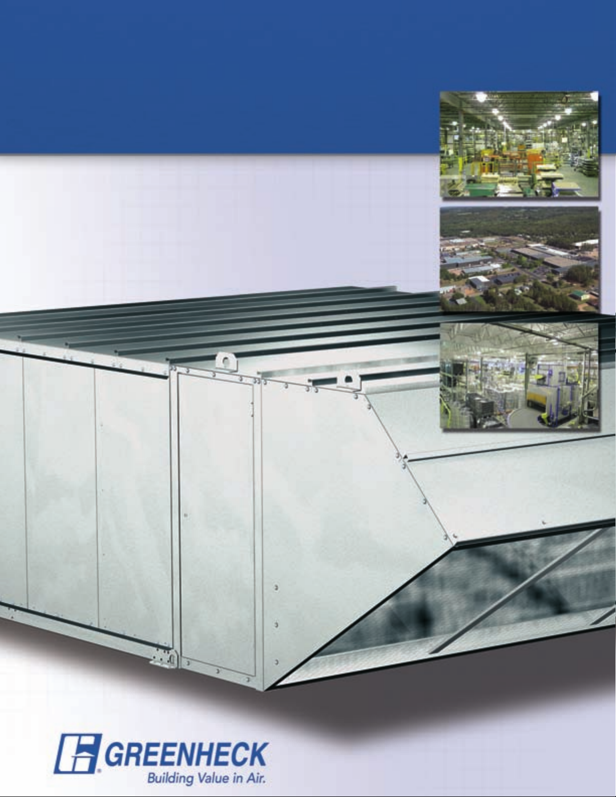
Page 1
Direct Gas-Fired Make-Up Air
Model TSU
Heavy Duty, High Airflow Applications
• Manufacturing and Industrial Facilities
• Up to 64,000 cfm
October
2005
Page 2
Products
®
Model TSU
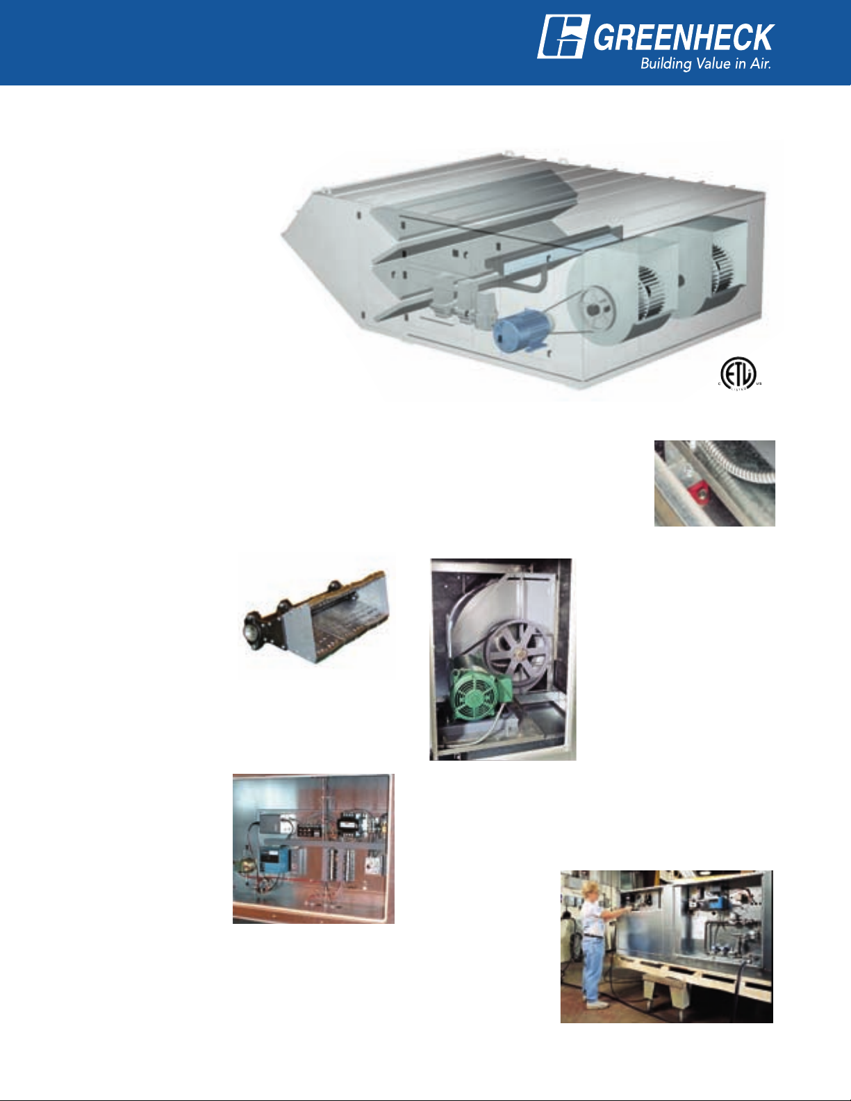
Direct Gas-Fired Make-Up Air Unit
The Greenheck model TSU is a
100% efficient direct gas-fired
heating and ventilating unit.
Airflow options include 100%
make-up air for constant volume
or variable volume applications.
For space heating, a
recirculation option is available.
The TSU is specifically designed
for providing heating and make-up
air for manufacturing facilities and
warehouses. Airflow volumes up to
64,000 cfm and heating capacities
up to 6,050,000 Btu/hr are offered.
TSU shown with optional weatherhood,
filter section and horizontal fan discharge.
Direct Gas-Fired Heat
Durable Construction
Designed for maximum weather resistance, TSU
housings are constructed of heavy gauge G90
galvanized steel. Lifting lugs are standard.
Direct Gas-Fired System
• Direct gas burners with
stainless steel mixing
plates
• Maxitrol burner modulation
control
• Flame safeguard with
digital fault indicator
capability
• 25:1 turn down ratio
Control Center
The control center includes the following standard
components:
• Magnetic motor starter
with solid state overload
protection
• Control transformer with
fusing
• Integral door interlocking
disconnect switch
• Separately fused motor
• Distribution terminal strip
Premium grade control components are selected
for reliable operation. All electrical components
are UL Listed, recognized or classified and factory
prewired for single point power connection.
Vibration Isolators
The entire fan and motor
assembly is mounted on vibration
isolators to minimize noise
transmission into the building.
Reliable Fan Performance
Air performance ratings from
Greenheck’s accredited test
chamber ensure accurate
data.
Double width, double inlet
forward curved wheels
for high efficiency and
low sound levels are
constructed of heavy gauge
steel. Wheels are balanced
to ensure vibration free
operation.
Access Doors and Panels
Large access doors and panels are provided for easy
inspection and maintenance of motors, drives, fan
wheels, filters, and heater controls.
Factory Wired
and Tested
All units are tested
prior to shipment.
Units are checked
for vibration and
proper operation.
2 3
Page 3
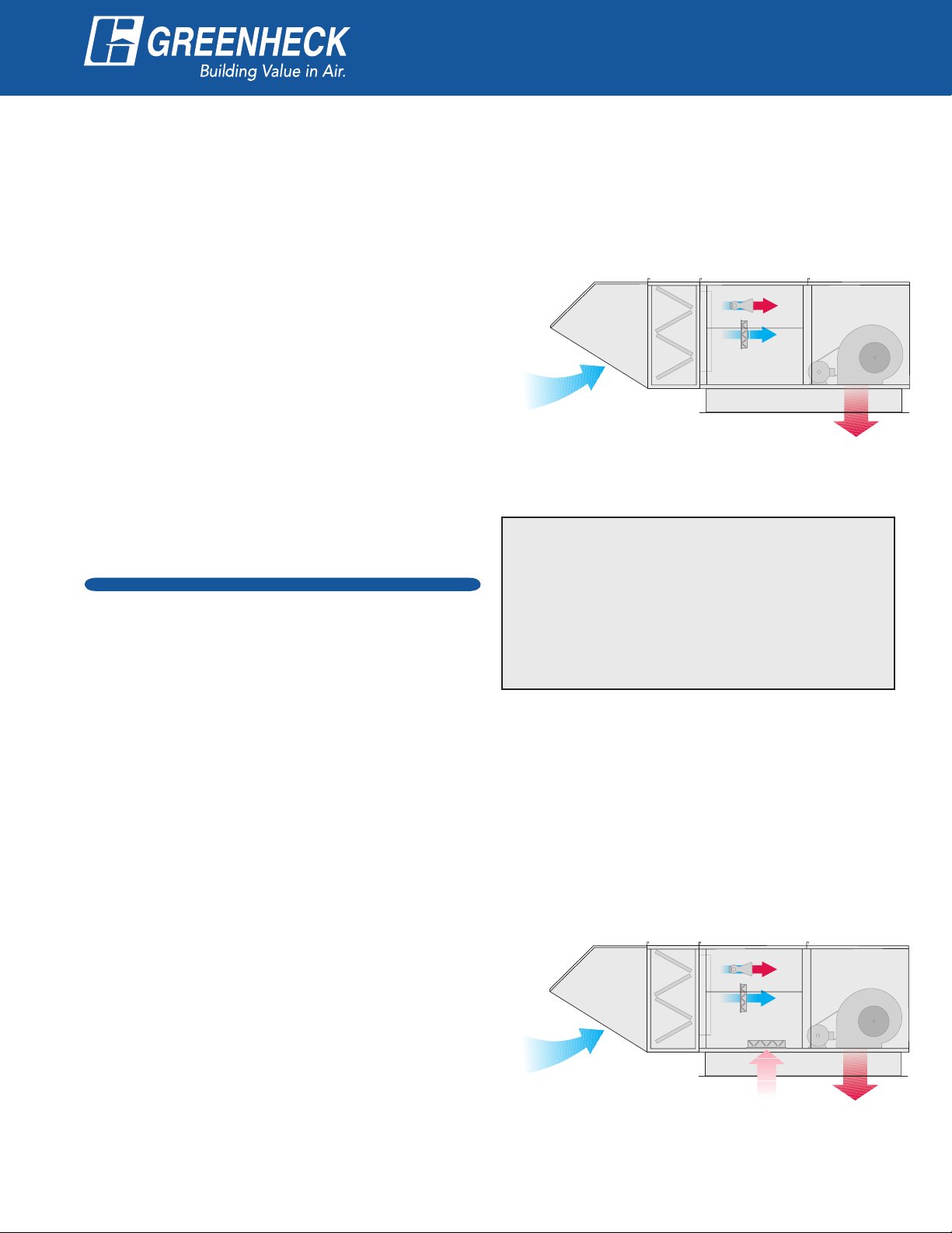
Variable Volume
®
Outside Air
Supply Air
Outside Air
Outside Air
Supply Air
Supply AirRecirculated
Air
The variable volume option is recommended when
a building’s exhaust volumes may vary. This option
enables the make-up air volume to track with the
exhaust volume, providing only the amount of makeup air that is required.
The variable volume TSU saves energy in two ways.
First, the fan power is reduced whenever makeup air requirements are less than the maximum.
Second, whenever lower air volumes are sufficient,
the TSU requires less gas to heat the outdoor air.
Airflow Control Strategies
Greenheck offers three methods of controlling the
make-up air volume. All three vary the fan speed for
maximum energy savings.
• Variable Frequency Drive controlled by building
pressure.
• Variable Frequency Drive controlled manually
with a remote potentiometer.
• 2 speed motor controlled manually with a remote
switch.
Recirculation
The Recirculation option is recommended when the
ventilation equipment provides the primary source of
heating for the space.
Application
Temperature Control
A Room Temperature Control package is included
with the Variable Volume systems. The space
temperature is controlled by a room mounted
thermostat. A factory supplied remote control panel
is required.
Burner By-Pass Damper
Both the Variable Volume and Recirculation option
include a patented burner by-pass damper, which
maintains the pressure drop across the burner as
air volumes change. This assures that complete and
proper combustion occurs. The by-pass damper is
self-adjusting, designed for minimal maintenance,
and requires no controls.
This option recirculates up to 80% of the supply air
and efficiently heats it to maintain the desired space
temperature. A minimum of 20% outdoor air is mixed
with the recirculated air to provide a continuous
source of fresh air.
Only outdoor air is used for combustion. This
eliminates the possibility of contaminants in the
recirculated air from crossing the burner.
Airflow Control Strategies
Greenheck offers four methods of controlling the
recirculated air to outdoor air ratio. The ratio is
determined by the outdoor air and recirculated
air damper positions. The methods for adjusting
damper positions are outlined below:
• Modulating actuator controlled by building
pressure.
• Modulating actuator controlled manually with a
remote potentiometer.
• Two position actuator controlled manually with
a remote switch.
• Manually operated damper quadrants set to a
fixed position.
In all cases, the fan provides a constant volume of
supply air.
Temperature Control
A Room Temperature Control package is included
with the Recirculation system. The space temperature
is controlled by a room mounted thermostat. A
factory supplied remote control panel is required.
Page 4

Accessories
®
Evaporative Cooling
The evaporative cooling section includes
a galvanized steel housing with a louvered
intake, 2-inch aluminum mesh filters
and stainless steel evaporative cooling
modules. The evaporative cooling media
is Munters GLASdek and has a 90%
cooling effectiveness. Airflow capacity for
evaporative cooling is up to 60,000 cfm.
The entire section mounts directly to
the intake end of the fan/heater section,
eliminating transition or ductwork by
others. Drain and overflow are conveniently
tapped through the front of the cooling
section. The supply line connection is
field located where convenient. Freeze
protection and automatic drain & fill options
are also available.
Additional Accessories
V-Bank Filters
Washable 2-inch aluminum mesh filters or 2-inch
disposable (30% efficient) filters are available.
Air Filter Gauge
The air filter gauge indicates when filters become
dirty. An indicator light may be wall/beam mounted or
provided with a remote control panel.
Motorized Dampers
Intake or discharge dampers are available to prevent
backdrafts when the fan is not in operation. Intake
dampers are factory mounted and wired.
Spring Vibration Isolation
Spring vibration isolators are available in lieu of
neoprene isolators.
Freezestat
An on/off type discharge duct stat (with a timer)
prevents the discharge of cold air into the building
when the burner is not providing adequate tempering.
Inlet Air Sensor
An on/off type duct stat automatically de-energizes
the gas system and interrupts the flow of gas to the
burner when the inlet air temperature is above the
desired setting.
Fiberglass Insulation
Fiberglass insulation is used to line the housing to
prevent the formation of condensation and to form an
acoustical barrier.
115 Volt GFCI Service Receptacle
A 115 volt GFCI outlet is mounted in the heater
control compartment for the convenience of field
service personnel. A separate 115 volt power source
is required.
Roof Curbs
Factory provided roof curbs are available to ensure
compatibility between make-up air unit and roof curb.
Standard construction is G90 galvanized steel. Curbs
ship knocked down.
Weatherhood
Standard construction is G90 galvanized steel.
Weatherhood for housing size 40 ships assembled
as standard.
Propane Gas
A propane heater may be provided in lieu of natural
gas.
Gas Pressure Regulator
Required if building gas line pressure exceeds 5 psi.
Special Coatings
Greenheck’s Permatector coating is available for
a durable, long lasting finish. Decorative paints
are also available in a variety of colors to match
existing building fixtures. Consult your Greenheck
representative for paint selections.
4 5
Page 5

Accessories
B
C
Airflow
Airflow
C
B
D
®
Remote Control Panels
A wide variety of remote control panels are available. Specify the desired combination of switches, thermostats,
temperature selectors and indicator lights (see examples below). A terminal strip within the remote control panel
makes connection to the TSU control center simple.
Basic remote
control panel
with thermostat
for room
temperature
control option.
Temperature Controls
Discharge Temperature Control
Control of discharge air temperature is accomplished
with a factory installed sensor located at the fan
discharge. A Maxitrol 14 system controls the gas
valve to provide the desired discharge temperature.
Room Override
This option, available with the Maxitrol
14 system, enables a room thermostat
to increase the TSU supply temperature
above its discharge temperature set
point. Discharge sensor is factory
installed. Room sensor may be wall/
beam mounted or included on a remote
control panel.
Remote panel
with circuit
analyzer and
thermostat for
room override
option.
Room Temperature Control
Specify this option when the TSU has the primary
responsibility for controlling the room temperature.
A room mounted thermostat (shown below) senses
the room temperature and provides feedback to the
Maxitrol 44 control system. The gas valves are then
modulated to satisfy the selected room temperature.
The thermostat is manually
adjustable to the desired room
temperature. The room thermostat
may be wall/beam mounted or
included on a remote control panel.
Discharge Arrangements
For installation flexibility, fan discharges are available in either Horizontal (HZ), Downblast (DB), or Upblast (UB)
configuration.
Arrangement HZ
Arrangement DB
Page 6

Air Performance
®
Housing Size 40
Model CFM
RPM 612 672 726 779
BHP 5.0 5.7 6.5 7.4
RPM 691 738 788 836 881 923
BHP 8.7 9.6 10.6 11.6 12.6 13.6
RPM
BHP 14.3 15.4 16.5 17.5 18.8 20.0
RPM 575 621 667 711 752 791
BHP
RPM 636 677 716 755 792 830
BHP 12.6 13.9 15.1 16.3 17.5 18.9
RPM 703 739 774 809 841 875
BHP 18.4 19.9 21.3 22.8 24.2 25.6
TSU-218
TSU-220
14,000
18,000
22,000
20,000
24,000
28,000
Housing Size 50
Model CFM
RPM 446 482 515 548
BHP 12.1 13.8 15.4 16.9
RPM 491 523 553 582 610 638
BHP 18.0 19.8 21.9 23.9 25.7 27.5
RPM
BHP 27.4 29.5 31.6 33.9 36.3 38.7
RPM 401 429 456 483 509 535
BHP 16.8 18.9 21.2 23.7 26.3 29.0
RPM 446
BHP 24.9
RPM 494 514
BHP
TSU-225
TSU-230
32,000
38,000
45,000
44,000
52,000
60,000
TOTAL STATIC PRESSURE IN INCHES OF WG
0.75 1.00 1.25 1.50 1.75 2.00
787 825 865 902 944 985
8.3 9.3 10.3 11.4 12.5 13.7
TOTAL STATIC PRESSURE IN INCHES OF WG
0.75 1.00 1.25 1.50 1.75 2.00
547 575 603 629 655 679
470 494 516 539 562
27.3 29.8 32.2 35.0 38.0
535 556 576 596
36.2 38.3 40.9 43.9 46.7 49.5
Maximum
MBH
1,830
2,350
2,875
2,610
3,135
3,600
Maximum
MBH
3,830
4,550
5,390
5,270
6,050
6,050
PRESSURE DROP DATA
Housing
Size
40
50
CFM
14,000 0.14 0.05
28,000 0.28 0.16
30,000 0.14 0.04
60,000 0.28 0.15
Note: The air performance data shown does not include internal static pressure losses due
to items such as filters and dampers. For exact air performance data based on specific unit
configuration, use the Greenheck CAPS selection program.
6 7
2-inch
30% Filter
Inlet
Damper
Gas
Burner
0.625
0.625
Page 7

A B
C
D
Direct Gas-Fired
E
C
D
®
DIMENSIONS
Dimensional Data
Housing
Size
40
50
All dimensions are shown in inches.
Width A B C D
110 46 25 88 51
156 71 31 100 64
Evaporative Cooling (with or without heating)
DIMENSIONS
Housing
Size
40
50
All dimensions are shown in inches.
Width C D E
110 88 51 88
156 100 64 100
Page 8

Typical Specifications
General: Make-up air unit shall be as manufactured by
Greenheck or approved equal provided all specifications
are met. Greenheck Model TSU equipment is used as the
basis of design. Performance to be as scheduled on plans.
Make-up air unit shall be ETL listed to ANSI Z83.4 - 1999,
CSA 3.7 - M99 (for 100% outdoor air) or ANSI Z83.18 - 2000
(for recirculation).
Gas Train and Controls: Direct gas-fired system shall have
a draw through design and field adjustable burner baffles.
Gas trains shall include a pilot ignition system and shall
have digital coded fault indicator capability. Fault indicator
shall provide service history by storing codes for the last
five faults. Dual safety shutoff valves shall be industrial
duty and use 120 VAC control signals. Temperature control
shall incorporate a Maxitrol electronic modulation control
system.
Unit Casing and Frames: Unit shall be of internal frame
type construction of galvanized steel. All frames and panels
shall be G90 galvanized steel. Where top panels are joined
there shall be a standing seam to insure positive weather
protection. All metal-to-metal surfaces exposed to the
weather shall be sealed, requiring no caulking at job site. All
components shall be easily accessible through removable
doors.
Insulation: Unit casing to be lined with 1-inch fiberglass
insulation. Insulation shall be in accordance with NFPA 90A
and tested to meet UL 181 erosion requirements. Double wall
shall be provided if specified.
Fan Section: Centrifugal fans shall be double width, double
inlet. The fan and the motor shall be mounted on a common
base and shall be internally isolated. All blower wheels shall
be balanced. Ground and polished steel fan shafts shall be
mounted in ball bearing pillow blocks. Bearings shall be
selected for a minimum (L10) life in excess of 100,000 hours
at maximum cataloged speeds.
Motors and Drives: Motors shall be energy efficient,
complying with EPACT standards, for single speed ODP
and TE enclosures. Motors shall be permanently lubricated,
heavy duty type, matched to the fan load and furnished at
the specified voltage, phase and enclosure. Drives shall be
sized for a minimum of 150% of driven horsepower. Pulleys
shall be cast and have machined surfaces, 10 horse power
and less shall be supplied with an adjustable drive pulley.
Electrical: All internal electrical components shall be prewired
for single point power connection. All electrical components
shall be UL Listed, recognized or
classified where applicable and wired in
compliance with the National Electrical
Code. Control center shall include motor
starter, control circuit fusing, control
transformer for 24 VAC circuit, integral
disconnect switch and terminal strip.
Contactors, Class 20 adjustable overload
protection and single phase protection
shall be standard.
Filter Section: Filters shall be mounted
in a V-bank arrangement such that
velocities across the filters do not exceed
550 feet per minute. Filters shall be
easily accessible through a removable
access panel.
Weatherhood: Weatherhood shall be
constructed of G90 galvanized steel
with birdscreen mounted at the intake.
Recirculation (optional): Recirculation airflow shall be
controlled by adjustment of return damper position. Input
signal for return damper shall be from building pressure
sensors, potentiometer or manual switch. Recirculated air
shall not be permitted to pass across the burner. A selfadjusting burner bypass damper shall maintain a constant air
volume across the burner to ensure proper gas combustion.
Bypass damper shall operate automatically without an
electronic input control signal.
Variable Volume (optional): Volume shall be varied by
either a 2-speed motor or variable frequency drive. Input
signal for fan speed shall be from building pressure sensors,
potentiometer or manual switch. A self-adjusting burner
bypass damper shall maintain a constant air volume across
the burner to ensure proper gas combustion. Bypass damper
shall operate automatically without an electronic input
control signal.
Evaporative Cooling Section (optional): Evaporative
cooling section shall include a galvanized steel housing with
louvered intake, 2 inch aluminum mesh filters and a stainless
steel evaporative cooling module all provided by the make-up
air unit manufacturer. The louver shall be stationary type with
drainable blades, designed to withstand wind loads of 25
PSF. Evaporative cooling media shall be Munters GLASdek
with a depth of 12 inches for a cooling effectiveness of 90%.
Drain and overflow connections shall be provided.
Our Warranty
Greenheck warrants this equipment to be free from defects in material and workmanship for a period of
one year from the purchase date. Any units or parts which prove defective during the warranty period will
be replaced at our option when returned to our factory, transportation prepaid. Motors are warranted by
the motor manufacturer for a period of one year. Should motors furnished by Greenheck prove defective
during this period, they should be returned to the nearest authorized motor service station. Greenheck will
not be responsible for any removal or installation costs.
As a result of our commitment to continuous improvement, Greenheck reserves the right to change
specifications without notice.
Greenheck P.O. Box 410 • Schofield, WI 54476-0410 • Phone (715) 359-6171 • greenheck.com
Copyright © 2005 Greenheck Fan Corp. • Catalog TSU Rev. 5 October 2005 SN
 Loading...