

Page 1
Document 472058
Models SQ and BSQ
®
Centrifugal Inline Fans
Installation, Operation and Maintenance Manual
Please read and save these instructions for future reference. Read carefully before attempting to assemble, install,
operate or maintain the product described. Protect yourself and others by observing all safety information. Failure
to comply with instructions could result in personal injury and/or property damage!
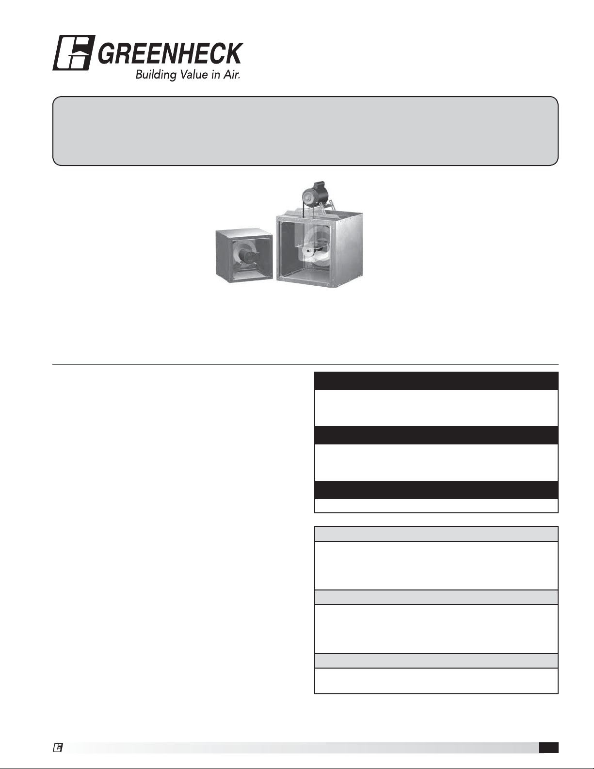
Model SQ Direct Drive
Model SQ is a direct drive
centrifugal inline exhaust fan. These
fans are specifically designed for
inline applications. Performance
capabilities range up to 5,000cfm
(8,500 m
(498 Pa) of static pressure. SQ fans
are available in thirteen sizes with
nominal wheel diameter ranging
from 6 to 16 inches (152 to 406 mm) (060 to 160
unit sizes). Each fan shall bear a permanently affixed
manufacturers engraved metal nameplate containing the
model number and individual serial number.
3
/hr) and up to 2.0 in.wg
General Safety Information
Only qualified personnel should install this fan.
Personnel should have a clear understanding of these
instructions and should be aware of general safety
precautions. Improper installation can result in electric
shock, possible injury due to coming in contact with
moving parts, as well as other potential hazards. Other
considerations may be required if seismic activity
is present. If more information is needed, contact a
licensed professional engineer before moving forward.
1. Follow all local electrical and safety codes, as
well as the National Electrical Code (NEC) and the
National Fire Protection Agency (NFPA), where
applicable. Follow the Canadian Electric Code
(CEC) in Canada.
2. The rotation of the wheel is critical. It must be free
to rotate without striking or rubbing any stationary
objects.
3. Motor must be securely and adequately grounded.
4. Do not spin fan wheel faster than max cataloged fan
RPM. Adjustments to fan speed significantly effects
motor load. If the fan RPM is changed, the motor
current should be checked to make sure it is not
exceeding the motor nameplate amps.
5. Do not allow the power cable to kink or come in
contact with oil, grease, hot surfaces or chemicals.
Replace cord immediately if damaged.
6. Verify that the power source is compatible with the
equipment.
7. Never open access doors to a duct while the fan is
running.
Model BSQ Belt Drive
Model BSQ is a belt drive centrifugal inline
exhaust fan. These fans are specifically
designed for inline applications.
Performance capabilities range up to
27,200 cfm (46,200 m
4.0 in. wg (996 Pa) of static pressure.
BSQ fans are available in fourteen
sizes with nominal wheel diameter
ranging from 7 to 42 inches (178 to
1067 mm) (070 to 420 unit sizes). Each fan shall bear
a permanently affixed manufacturers engraved metal
nameplate containing the model number and individual
serial number.
DANGER
Always disconnect, lock and tag power source before
installing or servicing. Failure to disconnect power
source can result in fire, shock or serious injury.
CAUTION
When servicing the fan, motor may be hot enough
to cause pain or injury. Allow motor to cool before
servicing.
CAUTION
Precaution should be taken in explosive atmospheres.
DANGER
Pour écarter les risques d’incendie, de choc électrique
ou de blessure grave, veiller à toujours débrancher,
verrouiller et étiqueter la source de courant avant
l’installation ou l’entretien.
ATTENTION
Lors de toute intervention sur la soufflante, le moteur
peut être suffisamment chaud pour provoquer une
douleur voire une blessure. Laisser le moteur refroidir
avant toute maintenance.
ATTENTION
Faire preuve de précaution dans les atmosphères
explosives.
3
/hr) and up to
®
Centrifugal Inline Fans 1
s
1
Page 2

Receiving
Upon receiving the product check to ensure all items
are accounted for by referencing the delivery receipt or
packing list. Inspect each crate or carton for shipping
damage before accepting delivery. Alert the carrier
of any damage detected. The customer will make
a notation of damage (or shortage of items) on the
delivery receipt and all copies of the bill of lading which
is countersigned by the delivering carrier. If damaged,
immediately contact your Greenheck Representative.
Any physical damage to the unit after acceptance is not
the responsibility of Greenheck Fan Corporation.
Unpacking
Verify that all required parts and the correct quantity
of each item have been received. If any items are
missing, report shortages to your local representative to
arrange for obtaining missing parts. Sometimes it is not
possible that all items for the unit be shipped together
due to availability of transportation and truck space.
Confirmation of shipment(s) must be limited to only
items on the bill of lading.
Handling
Move fan to desired location and determine position of
access panels, discharge and motor. Make sure the inlet
and outlet have at least 2½ times the wheel diameter
(duct diameter) before any obstructions like an elbow
or transition. Attach the fan to a suitable framework
as specified; hanging or base vibration isolators are
recommended. See the SQ & BSQ Fan Dimensions
table on page 3 for physical dimensions, utilizing
Figures 1 and 2. Mounting dimensions and vibration
isolator centerline information is provided on pages
4 and 5. The motor’s amperage and voltage ratings
must be checked for compatibility to supply voltage
prior to final electrical connection. Electrical lead-in
wires are then connected to the factory supplied safety
disconnect switch. All wiring must conform to local and
national codes.
Fan Storage
Fans are protected against damage during shipment. If
the unit cannot be installed and operated immediately,
precautions need to be taken to prevent deterioration of
the unit during storage. The user assumes responsibility
of the fan and accessories while in storage. The
manufacturer will not be responsible for damage during
storage. These suggestions are provided solely as a
convenience to the user.
Indoor Storage
The ideal environment for the storage of fans and
accessories is indoors, above grade, in a low humidity
atmosphere which is sealed to prevent the entry of
blowing dust, rain or snow. Temperatures should be
evenly maintained between 30° to 110°F (-1° to 43°C)
(wide temperature swings may cause condensation
and “sweating” of metal parts). All accessories must be
stored indoors in a clean, dry atmosphere.
Remove any accumulations of dirt, water, ice or snow
and wipe dry before moving to indoor storage. To avoid
“sweating” of metal parts allow cold parts to reach room
temperature. To dry parts and packages use a portable
electric heater to get rid of any moisture buildup. Leave
coverings loose to permit air circulation and to allow for
periodic inspection.
The unit should be stored at least 3½ in. (89 mm) off the
floor on wooden blocks covered with moisture proof
paper or polyethylene sheathing. Aisles between parts
and along all walls should be provided to permit air
circulation and space for inspection.
Outdoor Storage
Fans designed for outdoor applications may be stored
outdoors, if absolutely necessary. Roads or aisles for
portable cranes and hauling equipment are needed.
The fan should be placed on a level surface to prevent
water from leaking into the fan. The fan should be
elevated on an adequate number of wooden blocks so
that it is above water and snow levels and has enough
blocking to prevent it from settling into soft ground.
Locate parts far enough apart to permit air circulation,
sunlight and space for periodic inspection. To minimize
water accumulation, place all fan parts on blocking
supports so that rain water will run off.
Do not cover parts with plastic film or tarps as these
cause condensation of moisture from the air passing
through heating and cooling cycles.
Fan wheels should be blocked to prevent spinning
caused by strong winds.
Inspection and Maintenance During
Storage
While in storage, inspect fans once per month. Keep a
record of inspection and maintenance performed.
If moisture or dirt accumulations are found on parts,
the source should be located and eliminated. At each
inspection, rotate the wheel by hand ten to fifteen
revolutions to distribute lubricant on motor. If paint
deterioration begins, consideration should be given to
touch-up or repainting. Fans with special coatings may
require special techniques for touch-up or repair.
Machined parts coated with rust preventive should be
restored to good condition promptly if signs of rust
occur. Immediately remove the original rust preventive
coating with petroleum solvent and clean with lint-free
cloths. Polish any remaining rust from surface with
crocus cloth or fine emery paper and oil. Do not destroy
the continuity of the surfaces. Thoroughly wipe clean
with Tectyl® 506 (Ashland Inc.) or the equivalent. For
hard to reach internal surfaces or for occasional use,
consider using Tectyl® 511M Rust Preventive, WD-40
or the equivalent.
®
Removing From Storage
As fans are removed from storage to be installed in their
final location, they should be protected and maintained
in a similar fashion until the fan equipment goes into
operation.
Centrifugal Inline Fans2
®
Page 3
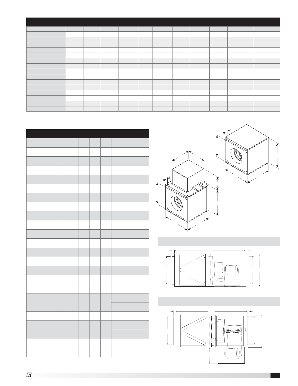
SQ & BSQ Fan Dimensions
Model A B C *D E *F *G *H Damper SQ Weight^ BSQ Weight^
SQ 60-75 12
SQ 80-95 15
BSQ 70-80 15
(305) 13 (330) 12 (305) 8
(381) 16 (406) 15 (381) 11
(381) 21 (533) 15 (381) 11
BSQ 90 15 (381) 21 (533) 15 (381) 117⁄8 (302) 1 (25) 151⁄2 (394) 14 (356) 121⁄2 (318) 12 (305) - 84 (38)
SQ-BSQ 100 17 (432) 21 (533) 17 (432) 137⁄8 (352) 1 (25) 151⁄2 (394) 14 (356) 121⁄2 (318) 14 (356) 56 (25) 83 (38)
SQ-BSQ 120 19 (483) 21 (533) 19 (483) 157⁄8 (403) 1 (25) 177⁄8 (454) 16 (406) 121⁄2 (318) 16 (406) 67 (30) 97 (44)
SQ-BSQ 130 (HP) 21 (533) 21 (533) 21 (533) 177⁄8 (454) 1 (25) 177⁄8 (454) 16 (406) 121⁄2 (318) 18 (457) 67 (35) 97 (44)
SQ-BSQ 140 (HP) 23 (584) 22 (559) 23 (584) 197⁄8 (505) 1 (25) 177⁄8 (454) 16 (406) 121⁄2 (318) 20 (508) 104 (47) 111 (50)
SQ-BSQ 160 (HP) 26 (660) 26 (660) 26 (660) 227⁄8 (581) 1 (25) 201⁄2 (521) 17 (432) 137⁄8 (340) 23 (584) 160 (73) 208 (94)
BSQ 180 (HP) 28 (711) 28 (711) 28 (711) 237⁄8 (606) 11⁄2 (38) 243⁄8 (619) 18 (457) 133⁄4 (349) 24 (610) 26 (12) 245 (111)
BSQ 200 (HP) 32 (813) 32 (813) 32 (813) 277⁄8 (708) 11⁄2 (38) 28 (711) 20 (508) 16 (406) 28 (711) 26 (12) 314 (142
BSQ 240 (HP) 39 (991) 34 (864) 39 (991) 347⁄8 (886) 11⁄2 (38) 327⁄8 (835) 22 (559) 19 (483) 35 (889) 26 (12) 415 (188)
BSQ 300 (HP) 46 (1168) 38 (965) 46 (1168) 417⁄8 (1064) 11⁄2 (38) 34 (864) 22 (559) 18 (457) 42 (1067) 26 (12) 537 (244)
BSQ 360 (HP) 52 (1321) 42 (1067) 52 (1321) 477⁄8 (1216) 11⁄2 (38) 34 (864) 22 (559) 18 (457) 48 (1219) 26 (12) 686 (311)
BSQ 420 (HP) 58 (1473) 50 (1270) 58 (1473) 537⁄8 (1368) 11⁄2 (38) 34 (864) 22 (559) 18 (457) 54 (1372) 26 (12) 789 (358)
All dimensions in inches (millimeters) and weight is shown in pounds (kilograms). *May be greater depending on motor.
^Weight shown is largest cataloged Open Drip Proof motor.
7
⁄8 (225) 1 (25) --
7
⁄8 (302) 1 (25)
7
⁄8 (302) 1 (25) 151⁄2 (394) 14 (356) 121⁄2 (318) 12 (305) - 76 (34)
---
-
9 (229) 26 (12) -
12 (305) 41 (19) -
E
Filter Option Dimensions
40
(18)
74
(34)
88
(40)
114
(52)
120
(54)
174
(79)
246
117
(53)
120
(54)
144
(79)
140
(64)
181
(82)
294
344
441
573
759
957
Filter
Size
10 x 12
(254 x 305)
14 x 25
(356 x 635)
16 x 20
(406 x 508)
16 x 25
(406 x 635)
20 x 20
(508 x 508)
20 x 25
(508 x 635)
20 x 20
(508 x 508)
14 x 25
(356 x 635)
16 x 20
(406 x 508)
16 x 25
(406 x 635)
20 x 20
(508 x 508)
20 x 25
(508 x 635)
20 x 20
(508 x 508)
20 x 25
(508 x 635)
12 x 25
(305 x 635)
16 x 25
(406 x 635)
20 x 25
(508 x 635)
16 x 25
(406 x 635)
20 x 25
(508 x 635)
16 x 25
(406 x 635)
20 x 25
(508 x 635)
16 x 25
(406 x 635)
20 x 25
(508 x 635)
Model A B C D WT.
1
⁄8
12
(305)
15
(381)
17
(432)
19
(483)
21
(533)
23
(584)
26
(660)
15
(381)
17
(432)
19
(483)
21
(533)
23
(584)
26
(660)
28
(711)
32
(813)
39
(991)
46
(1168)
52
(1321)
58
(1473)
87⁄8
(225)1 (25)
117⁄8
(302)1 (25)
137⁄8
(352)1 (25)
157⁄8
(403)1 (25)
177⁄8
(454)1 (25)
197⁄8
(505)1 (25)
227⁄8
(581)1 (25)
117⁄8
(302)1 (25)
137⁄8
(352)1 (25)
157⁄8
(403)1 (25)
177⁄8
(454)1 (25)
197⁄8
(505)1 (25)
227⁄8
(581)1 (25)
237⁄8
(606)
277⁄8
(708)
347⁄8
(886)
417⁄8
(1064)
477⁄8
(1216)
537⁄8
(1368)
11⁄2
(38)
11⁄2
(38)
11⁄2
(38)
11⁄2
(38)
11⁄2
(38)
11⁄2
(38)
(112)
(133)
(156)
(200)
(260)
(344)
(434)
1185
(538)
SQ 60-75
SQ 80-95
SQ 100
SQ 120
SQ 130
SQ 140
SQ 160
BSQ 70-80-90
BSQ 100
BSQ 120
BSQ 130 (HP)
BSQ 140 (HP)
BSQ 160 (HP)
BSQ 180 (HP)
BSQ 200 (HP)
BSQ 240 (HP)
BSQ 300 (HP)
BSQ 360 (HP)
BSQ 420
Note: 24-inch side clearance is recommended for accessing and removing filters. All
dimensions in inches (millimeters) and weight (WT.) in pounds (kilograms).
22
(562)
5
45
(1159)
1
47
(1200)
3
52
(1326)
3
46
(1178)
3
52
(1330)
3
51
(1305)
5
50
(1286)
1
47
(1200)
3
52
(1326)
3
46
(1178)
3
52
(1330)
3
51
(1305)
1
55
(1399)
11
66
(1694)
7
68
(1749)
1
72
(1832)
1
79
(2013)
1
93
(2365)
⁄8
⁄4
⁄16
⁄8
⁄8
⁄8
⁄8
⁄4
⁄16
⁄8
⁄8
⁄8
⁄16
⁄16
⁄8
⁄8
⁄4
⁄8
Filter
Quantity
1
1
2
2
2
2
4
1
2
2
2
2
4
4
3
3
4
4
8
10
5
5
10
D
F
E
G
C
H
B
Figure 1:
SQ Dimensions
D
A
C
B
Figure 2:
BSQ Dimensions
Figure 3: Model SQ - Filter Options
D
C
A
D
B
C
Figure 4: Model BSQ - Filter Options
D
C
Optional cover varies
with motor size.
Recommend 24 in.
clearance.
A
D
C
B
A
®
Centrifugal Inline Fans 3
Page 4
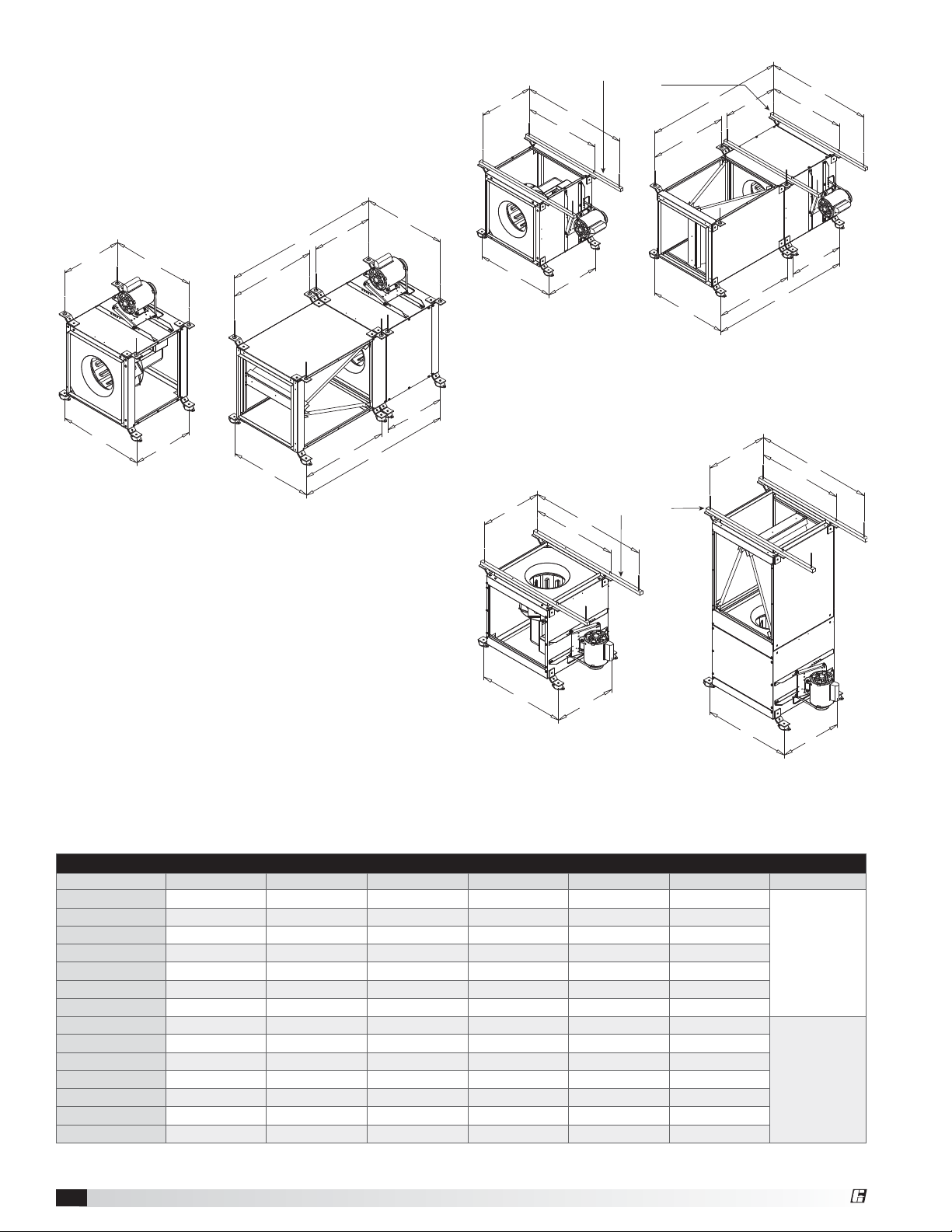
Mounting: SQ /BSQ
All SQ and BSQ fan models can be mounted
horizontally, vertically or at an angle. For ease of
installation, knockouts are provided at each location
where mounting brackets are shown in Figures 5, 6 and
7. Optional brackets are universally adjustable to mount
in any of these locations.
Hanging rails
by others
A
G
B
E
A
F
G
B
A
E
A
C
F
A
C
C
Figure 5
Horizontal Hanging or Base Mount
A
F
E
C
With either a hanging or base mount the motor may
be located on either side. The base mount allows top
access panels only.
B
Figure 6
Horizontal Hanging or Base Mount
A
F
E
B
With a hanging mount, the motor may be located on
either top or bottom. The base mount allows top motor
location only. Both options provide access panels on
two sides.
A
D
Hanging rails
D
B
by others
G
G
B
B
Figure 7
Vertical Hanging or Base Mount
D
Mounting brackets are turned 90° for vertical mounting.
Access panels are located on the two sides adjacent to
the motor.
Mounting Dimensional Data
Model A B C D E F G
SQ 60-75 10
SQ 80-95 13
BSQ 70-90 185⁄8 (473) 201⁄8 (511) 183⁄4 (476) 117⁄8 (302) 485⁄16 (1227) 273⁄8 (695)
SQ-BSQ 100 185⁄8 (473) 221⁄8 (562) 203⁄4 (527) 137⁄8 (352) 447⁄8 (1140) 24 (610)
SQ-BSQ 120 185⁄8 (473) 24 (610) 223⁄4 (578) 16 (406) 493⁄8 (1254) 281⁄8 (714)
SQ-BSQ 130 185⁄8 (473) 261⁄8 (664) 243⁄4 (629) 177⁄8 (454) 44 (1118) 23 (584)
SQ-BSQ 140 195⁄8 (498) 281⁄8 (714) 263⁄4 (679) 197⁄8 (505) 501⁄16 (1272) 28 (711)
SQ-BSQ 160 231⁄2 (597) 31 (787) 293⁄4 (756) 227⁄8 (581) 495⁄8 (1260) 235⁄8 (600)
BSQ 180 25
BSQ 200 291⁄8 (740) 37 (940) 333⁄4 (857) 263⁄4 (679) 643⁄16 (1630) 321⁄4 (819)
BSQ 240 315⁄8 (803) 441⁄4 (1124) 403⁄4 (1035) 337⁄8 (860) 661⁄2 (1689) 321⁄8 (816)
BSQ 300 35 (889) 51 (1295) 473⁄4 (1213) 407⁄8 (1038) 691⁄8 (1756) 313⁄8 (797)
BSQ 360 383⁄4 (974) 571⁄4 (1454) 531⁄2 (1359) 463⁄4 (1187) 76 (1930) 3411⁄16 (881)
BSQ 420 471⁄8 (1197) 63 (1600) 597⁄8 (1521) 597⁄8 (1521) 901⁄2 (2299) 401⁄2 (1029)
All dimensions in inches (millimeters).
5
⁄8 (270) 17 (432) 153⁄4 (400) 87⁄8 (225) 193⁄4 (502) 7 (178)
1
⁄4 (337) 20 (508) 183⁄4 (476) 117⁄8 (302) 43 (1092) 273⁄8 (695)
1
⁄2 (648) 331⁄2 (851) 299⁄16 (751) 223⁄4 (578) 529⁄16 (1335) 241⁄2 (622)
B
D
Hanging rails
not included.
Supplied by
others.
Hanging rails
not included.
Supplied by
others.
Centrifugal Inline Fans4
®
Page 5

Duct Length: The inlet and outlet duct length should be
approximately two to three wheel diameters long before
and after the fan to achieve cataloged performance.
Left Side
Discharge
Figure 8
Inlet
Width
Inline
Discharge
Height
Right Side
Discharge
Side Discharge: Make sure discharge is orientated in
the same direction as originally ordered, performance
will change with different discharge positions. Refer to
Figure 8 for proper side discharge definition and the
Side Discharge chart for dimensions. Refer to the CAPS
program or consult factory for performance corrections.
Side Discharge Duct Openings
Unit Size Width Height
BSQ 70-80-90 11
SQ 60-75 97⁄8 (251) 87⁄8 (225)
SQ 80-95 127⁄8 (327) 117⁄8 (302)
SQ 100/BSQ 100 137⁄8 (352) 137⁄8 (352)
SQ 120/BSQ 120 157⁄8 (403) 157⁄8 (403)
SQ 130/BSQ 130 (HP) 177⁄8 (454) 177⁄8 (454)
SQ 140/BSQ 140 (HP) 197⁄8 (505) 197⁄8 (505)
SQ 160/BSQ 160 (HP) 227⁄8 (581) 227⁄8 (581)
BSQ 180 (HP) 237⁄8 (606) 237⁄8 (606)
BSQ 200 (HP) 277⁄8 (708) 277⁄8 (708)
BSQ 240 (HP) 287⁄8 (733) 347⁄8 (886)
BSQ 300 (HP) 317⁄8 (810) 417⁄8 (1064)
BSQ 360 (HP) 327⁄8 (835) 377⁄8 (962)
BSQ 420 347⁄8 (886) 437⁄8 (1114)
All dimensions in inches (millimeters).
7
⁄8 (302) 117⁄8 (302)
Standing Neoprene Isolator
Standing Spring Isolator
5/8 inch
(16 mm)
nominal
Hanging Neoprene IsolatorHanging Spring Isolator
K
H
H
2
(51)
2
(51)
J
63⁄4
(171)
63⁄4
(171)
25⁄16
(59)
25⁄8
(67)
J
Isolator Dimensional Data
Model H I J K L
J
H
L
J
H
SQ 60-75
SQ 80-95
BSQ 70-90
SQ-BSQ 100
SQ-BSQ 120
SQ-BSQ 130
SQ-BSQ 140
SQ-BSQ 160
BSQ 180
BSQ 200
BSQ 240
BSQ 300
BSQ 360
BSQ 420
All dimensions in inches (millimeters).
1
(35)
1
(35)
3
⁄8
51⁄2
(140)
3
⁄8
51⁄2
(140)
I
®
Centrifugal Inline Fans 5
Page 6

Pre Start-Up Checks
1. Check all fasteners for tightness. The wheel
should rotate freely and be aligned as shown in
Figure 9. Wheel position is preset and the unit is
tested at the factory. Movement may occur during
shipment, and realignment may be necessary.
Centering can be accomplished by loosening
the bolts holding the inlet (venturi) panel and
repositioning. Wheel and inlet cone overlap can be
adjusted by loosening the setscrews in the wheel
and moving the wheel to the desired position.
3. Vibration Isolators: After fan is moved to desired
location, punch out the four knockout holes which
are located on the unit top and bottom panels.
Assemble the brackets to the unit according to
the appropriate drawings on page5 and refer to
respective parts list on page11. Make certain all
connectors are tight and that all washers are in.
4. For BSQ Fans: If adjustments are made, it is very
important to check the pulleys for proper alignment.
Misaligned pulleys lead to excessive belt wear,
vibration, noise, and power loss. (see Figure 11).
Wheel Overlap Dimensions
Model
SQ 60-95
SQ 100-160 1/4 (6)
BSQ 70-160 1/4 (6) -
BSQ 180-240 3/8
BSQ 300-420 1/2 (13)
Figure 9
G - Overlap
in. (mm)
-
(10)
G
H
2. Wheel Rotation: Direction of wheel rotation is
critical. Reversed rotation will result in poor air
performance, motor overloading and possible
burnout. Check wheel rotation by momentarily
energizing the unit
(all SQ and BSQ
fans have clockwise
wheel rotation when
viewed from top of
fan). Rotation should
be clockwise as
shown in Figure 10
and correspond to the
rotation decal on the
unit.
Figure 10
H - Gap
in. (mm)
1/8 (3)
-
-
-
CORRECT
WRONG
Figure 11
WRONG
WRONG
5. For BSQ Fans: Belt tension can be adjusted by
loosening four fasteners marked “R” on the drive
frame. (refer to Figure 13 on page 7). The motor
plate slides on the slotted adjusting arms. Belt
tension should be adjusted to allow 1/64 inch
e
s
i
w
k
c
o
l
C
of deflection per inch of belt span. For example,
a 15inch belt span should have 15/64 inch (or
about 1/4 inch) of deflection with moderate thumb
pressure at mid-point between pulleys (see
Figure12). Over-tightening will cause excessive
bearing wear and noise. Too little tension will cause
slippage at start-up and uneven wear.
WARNING
Correct direction of wheel rotation is critical. Reversed
rotation will result in poor air performance, motor
overloading and possible burnout.
AVERTISSEMENT
La turbine doit impérativement tourner dans le bon
sens. Une rotation en sens inverse entraînerait de
mauvaises performances de soufflage, une surcharge
du moteur voire un grillage du moteur.
Centrifugal Inline Fans6
®
Page 7

Figure 12
Belt Span
Deflection =
Belt Span
64
R
NOTE: Identical fasteners on opposing side must
also be loosened.
Figure 13
6. The adjustable motor pulley is factory set for the
RPM specified. Speed can be increased by closing
or decreased by opening the adjustable motor
sheave. Two groove variable pitch pulleys must be
adjusted an equal number of turns open or closed.
Any increase in speed represents a substantial
increase in the horsepower required by a unit. Motor
amperage should always be checked to avoid
serious damage to the motor when speed is varied.
Operation: SQ / BSQ
1. Before starting up or operating fan, check all
fasteners for tightness. In particular, check the
setscrews in wheel hub (and pulleys, if applicable).
2. While in the OFF position or before connecting the
fan to power, turn the fan wheel by hand to be sure
it is not striking the venturi or any obstacle.
3. Start the fan and shut it off immediately to check
rotation of the wheel with directional arrow in the
motor compartment, see Figure 10.
4. When the fan is started, observe the operation and
check for any unusual noises.
5. With the system in full operation and all ductwork
attached, measure current input to the motor and
compare with the nameplate rating to determine if
the motor is operating under safe load conditions.
6. Keep inlets and approaches to fan clean and free
from obstruction.
Inspection: SQ / BSQ
Inspection of the fan should be conducted at the
first 30 minute and 24 hour intervals of satisfactory
operation.
30 Minute Interval
Inspect bolts, setscrews and motor mounting bolts.
Adjust and tighten as necessary.
24 Hour Interval
Check all internal components. On BSQ unit only,
inspect belt alignment and tension. Adjust and tighten
as necessary.
IMPORTANT
The fan has been checked for mechanical noises at
the factory prior to shipment. If mechanical noise
should develop, suggested corrective actions are
offered in the Troubleshooting section.
IMPORTANT
Over-tightening will cause excessive bearing wear and
noise. Too little tension will cause slippage at start-up
and uneven wear.
IMPORTANT
Adjust (tighten) belt tension after the first 24-48 hours
of operation.
®
Centrifugal Inline Fans 7
Page 8
Maintenance: SQ / BSQ
Installation and maintenance are to be performed only
by qualified personnel who are familiar with local codes
and regulations and who are experienced with this type
of equipment.
Motor maintenance is generally limited to cleaning
and lubrication (where applicable). Cleaning should be
limited to exterior surfaces only. Removing dust buildup
on motor housing ensures proper motor cooling.
Greasing of motors is only intended when fittings are
provided. Many fractional horsepower motors are
permanently lubricated and should not be lubricated
after installation. Motors supplied with grease fittings
should be greased in accordance with manufacturers’
recommendations. Where motor temperatures do not
exceed 104ºF (40ºC), the grease should be replaced
after 2,000 hours of running time as a general rule.
Wheels require very little attention when moving clean
air. Occasionally, oil and dust may accumulate causing
imbalance. When this occurs the wheel and housing
should be cleaned to ensure smooth and safe operation.
All fasteners should be checked for tightness each time
maintenance checks are performed prior to restarting
unit.
A proper maintenance program will help these units
deliver years of dependable service.
DANGER
Always disconnect, lock and tag power source before
servicing. Failure to disconnect power source can
result in fire, shock or serious injury.
DANGER
Pour écarter les risques d’incendie, de choc électrique
ou de blessure grave, veiller à toujours débrancher,
verrouiller et étiqueter la source de courant avant
l’installation ou l’entretien.
IMPORTANT
Uneven cleaning of the wheel will produce an out of
balance condition that will cause vibration in the fan.
WARNING
This unit should be made non-functional when
cleaning the wheel or housing (fuses removed,
disconnect locked off).
WARNING
L’appareil doit être rendu non opérationnel lors du
nettoyage de la turbine ou du caisson (fusibles retirés,
sectionneur verrouillé).
Belt/Bearing Maintenance BSQ Unit
1. Belts tend to stretch after a period of time. They
should be checked periodically for wear and
tightness. When replacing belts, use the same type
as supplied with the unit.
2. Matched belts should always be used on units with
multi-groove pulleys.
3. For belt replacement, loosen the tensioning device
enough to allow removal of the belt by hand. Do not
force belts on or off. This may cause cords to break,
leading to premature belt failure.
4. Once installed, adjust belts as shown in “Pre-StartUp Checks.”
5. Shaft bearings can be classified in two groups:
relubricating and non-relubricating. All bearings on
standard model BSQ fans are factory lubricated
and require no further lubrication under normal
use (between -20ºF and 180ºF in a relatively clean
environment).
6. Units installed in hot, humid or dirty locations should
be equipped with special bearings. These bearings
will require frequent lubrication. Caution should be
employed to prevent overpacking or contamination.
7. Grease fittings should be wiped clean. The unit
should be in operation while lubricating. Extreme
care should be used around moving parts.
8. Grease should be pumped in very slowly until a
slight bead forms around the seal. A high grade
lithium base grease should be used.
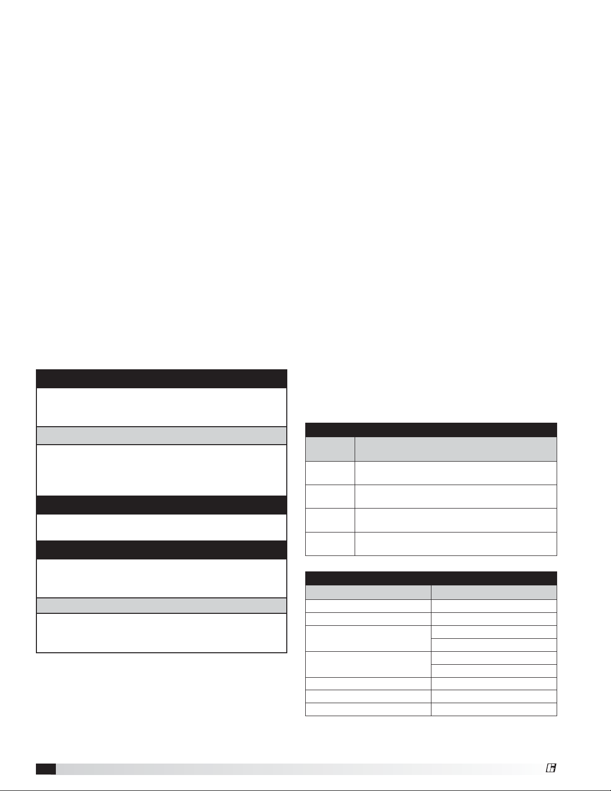
Recommended Relubrication Frequency
in Months
NOTE: If unusual environment conditions exist (extreme
temperature, moisture or contaminants) more frequent
lubrication is required.
A good quality lithium base grease, conforming to NLGI
Grade 2 consistency, such as those listed here may be
used.
Suggested Fan Bearing Greasing Intervals
Interval
(months)
1 to 3
3 to 6
6 to 12
12 to 18
Manufacturer Grease (NLGI #2)
U.S. Electric Motors Grease No. 83343
Chevron U.S.A. Inc Chevron SRI Grease #2
Mobil Oil Corporation
Texaco, Inc.
Amoco Oil Co. Rykon Premium #2
Exxon Unirex N2
Shell B Shell Alvania #2
Heavy duty in dirty, dusty locations; high ambient
temperatures; moisture laden atmosphere; vibration.
12 to 24 hours per day, heavy duty, or if moisture is
present
8 to 16 hours per day in clean, relatively dry
atmosphere
Infrequent operation or light duty in clean
atmosphere
Grease Manufacturers
Type of Service
Mobilith
Mobil 532
Premium BRB #2
Texaco Multifak #2
Centrifugal Inline Fans8
®
Page 9

Maintenance Documentation
Job Information
Job Name: ___________________________________ Service Organization: ______________________________
Address: _____________________________________ Address: _________________________________________
City: ________________________________________ City: _____________________________________________
State: _______________ Zip: __________________ State: ____________ Zip: __________________________
Phone: ______________________________________ Phone: ___________________________________________
Contact Person: ______________________________ Work Done By: ____________________________________
Nameplate Information Field Start-Up Documentation
Model: ______________________________________
Volts: _________ Hertz: ________ Phase: ______ Actual Voltage: _________ Hertz: _____ Phase: _____
Amps: _______________ Mark: ________________ Actual Amperage: _________________________________
Supply hp: ___________ Exhaust hp: ___________ Blower Rotation: __________________________________
Serial Number: _______________________________ Air Volume: Design cfm: _________________________
Model Voltage: _______________________________ Actual cfm: __________________________
Motor Amperage: _____________________________ Level of fan (L or H): _______________________________
Fan RPM: ____________________________________ Fan RPM Range (min.) _________ (max.) ____________
Maintenance Log
Date ___________________Time _____________ AM/PM
Notes: ___________________________________________
_________________________________________________
_________________________________________________
_________________________________________________
Date ___________________Time _____________ AM/PM
Notes: ___________________________________________
_________________________________________________
_________________________________________________
_________________________________________________
Date ___________________Time _____________ AM/PM
Notes: ___________________________________________
_________________________________________________
_________________________________________________
_________________________________________________
Date ___________________Time _____________ AM/PM
Notes: ___________________________________________
_________________________________________________
_________________________________________________
_________________________________________________
Date ___________________Time _____________ AM/PM
Notes: ___________________________________________
_________________________________________________
_________________________________________________
_________________________________________________
Date ___________________Time _____________ AM/PM
Notes: ___________________________________________
_________________________________________________
_________________________________________________
_________________________________________________
Date ___________________Time _____________ AM/PM
Notes: ___________________________________________
_________________________________________________
_________________________________________________
_________________________________________________
®
Date ___________________Time _____________ AM/PM
Notes: ___________________________________________
_________________________________________________
_________________________________________________
_________________________________________________
Centrifugal Inline Fans 9
Page 10

Parts List
Each fan bears a manufacturer’s nameplate with model number and serial number embossed. This information will
assist the local Greenheck representative and the factory in providing service and replacement parts. Before taking
any corrective action, make certain unit is not capable of operation during repairs.
CAUTION
A fan manufactured with an explosion resistant motor
does not certify the entire unit to be explosion proof.
Refer to ULListing Mark for the fans approved usage.
SQ Direct Drive Centrifugal Inline Exhaust Fan
MOTOR
WHEEL
VENTURI
HOUSING
COVER
MOTOR
ACCESS
PANEL
MOTOR
CAUTION
La présence d’un moteur antidéflagrant sur un
ventilateur ne garantit pas que tout l’appareil est
antidéflagrant. Pour connaître les emplois autorisés
de l’appareil, voir son marquage de conformité UL.
VENTURI
PANEL
WHEEL
ACCESS
PANEL
MOTOR
COVER
VENTURI
HOUSING
WHEEL
BEARING
SUPPORT
SHAFT
MOTOR
BSQ Belt Drive Centrifugal Inline Exhaust Fan
BEARINGS
BEARING
COVER
BELT
MOTOR
PULLEY
ACCESS
DOOR
SHAFT
PULLEY
BELT
TUBE
MOTOR
SUPPORT
ANGLES
MOTOR
PLATE
VENTURI
PANEL
MOTOR
WHEEL
ACCESS
DOOR
BEARING
COVER
BELT
TUBE
BELT
MOTOR
PULLEY
Centrifugal Inline Fans10
®
Page 11

Isolator Parts List
STANDING SUPPORT ISOLATOR HANGING SUPPORT ISOLATOR
6
5
7
No. Qty. Description
18
28
34
Cadium plated
hex head bolts
Cadium plated
hex nuts
Cadium plated
hex head bolts
Std. mount
48
bracket with (2)
7/16 in. holes
520
612
74
84
Cadium plated
washer
Cadium plated
lock washer
Cadium plated
washer
Neoprene or
Spring Isolator
2
Unit side panel
4
6
1
5
4
3
6
5
8
SQ-160
BSQ-160 thru 420
No. Qty. Description
1
2
5
5
Base fastener
by installer
SQ-60 thru 140
BSQ-100 thru 140
3/8 in. - 16 x 1 in. 3/8 in. - 16 x 1 1/4 in. 1 8
3/8 in. - 16 3/8 in. - 16 2 16
5/16 in. - 18 x 1 in. 3/8 in. - 16 x 1 in. 3 4
3/16 in. 1/4 in. 4 4
7/8 in. O.D. x
3/8 in. I.D. x 1/16 in.
7/8 in. O.D. x
3/8 in. I.D. x 1/16 in.
524
3/8 in. 3/8 in. 6 12
1 3/8 in. O.D. x
9/16 in. I.D. x
3/32 in.
Reference appropriate table below for
replacement Isolator(s)
1 3/8 in. O.D. x
9/16 in. I.D. x
3/32 in.
712
84
NOTE: Top bracket
is reversible for
mounting unit 90º
from indicated.
4
1
5
7
5
6
2
Cadium plated
hex head bolts
Cadium plated
hex nuts
Std. mount
bracket with (1)
1/4 in. hole
Std. mount
bracket with (2)
7/16 in. holes
Cadium plated
washer
Cadium plated
lock washer
Cadium plated
washer
Neoprene or
Spring Isolator
3
2
6
2
5
5
Unit side panel
5
7
8
7
1
5
6
2
SQ-60 thru 140
BSQ-100 thru 140
BSQ-160 thru 420
3/8 in. - 16 x 1 in. 3/8 in. - 16 x 1 1/4 in.
3/8 in. - 16 3/8 in. - 16
3/16 in. 1/4 in.
3/16 in. 1/4 in.
7/8 in. O.D. x
3/8 in. I.D. x 1/16 in.
7/8 in. O.D. x
3/8 in. I.D. x 1/16 in.
3/8 in. 3/8 in.
1 3/8 in. O.D. x
9/16 in. I.D. x
3/32 in.
1 3/8 in. O.D. x
9/16 in. I.D. x
3/32 in.
Reference appropriate table below for
replacement Isolator(s)
SQ-160
REPLACEMENT SPRING ISOLATOR(S)
MODEL FAN SIZES
BSQ ---- 70-130 140-180 200 240-300 360-420
SQ 60-100 120-140 160 ---- ---- ----
BASE MOUNT
HANGING
FDS-1-35
BLUE
SH-1-35
BLUE
FDS-1-70
GREEN
SH-1-70
GREEN
FDS 1-120
GRAY
SH-1-125
GRAY
FDS 1-120
GRAY
SH-1-245
BROWN
FDS-1-220
BROWN
SH-1-245
BROWN
REPLACEMENT NEOPRENE ISOLATOR(S)
MODEL FAN SIZE
BSQ 70-140 160-200 240-420
SQ 60-140 160 ----
BASE MOUNT R-1 GREEN R-2 BLACK R-2 RED
HANGING 40DUR BLACK 50DUR BLACK 50DUR BLACK
®
Centrifugal Inline Fans 11
FDS-1-370
ORANGE
SH-1-370
ORANGE
Page 12
Troubleshooting
WARNING
Before taking any corrective action, make certain unit
is not capable of operation during repairs.
PROBLEM CAUSE CORRECTIVE ACTION
Wheel unbalance
Clean all dirt off wheel. Check wheel balance, rebalance in
place if necessary.
Bad bearings Replace.
Excessive noise
or vibration
Belts too tight or too loose Adjust tension, see Figure 12.
Wheel improperly aligned and
rubbing
Center wheel on inlet, see Figure 9.
Loose drive or motor pulleys Align and tighten. See “Pre Start-Up Checks”, see page 6-7.
Reduced airflow
Foreign objects in wheel or
housing
System resistance too high
Unit running backwards Correct as shown in Figure 10.
Remove objects, check for damage or unbalance.
Check system: Proper operation of backdraft or control
dampers, obstruction in ductwork, clean dirty filters.
Excessive dirt buildup on wheels Clean wheel.
Improper wheel alignment Center wheel on inlets, see Pre Start-Up Checks and Figure 9.
Avant d’entreprendre toute action corrective, s’assurer
que l’appareil ne pourra pas fonctionner durant les
réparations.
AVERTISSEMENT
Our Commitment
As a result of our commitment to continuous improvement, Greenheck reserves the right to change specifications
without notice.
Specific Greenheck product warranties are located on greenheck.com within the product area tabs and in the
Library under Warranty.
Greenheck’s Centrifugal Inline Fans catalog, Models SQ
and BSQ provides additional information describing the
equipment, fan performance, available accessories, and
specification data.
®
Phone: 715.359.6171 • Fax: 715.355.2399 • Parts: 800.355.5354 • E-mail: gfcinfo@greenheck.com • Website: www.greenheck.com
472058 • SQ and BSQ, Rev. 3, October 2011 Copyright 2011 © Greenheck Fan Corporation12
AMCA Publication 410-96, Safety Practices for Users and
Installers of Industrial and Commercial Fans, provides
additional safety information. This publication can be obtained
from AMCA International, Inc. at www.amca.org.
 Loading...