

Page 1
r
Document Number 461338
®
SMD-XXX, SMD-XXXV, SESMD-XXX,
SSSMD-XXX,SMDRXXX, SESMDR-XXX,
AND SSSMDR-XXX MODELS
Leakage Rated Smoke Dampers
Vertical or Horizontal Mount
Installation, Operation and Maintenance Instructions
These instructions apply to the installation of SMD-XXX, SESMD-XXX SSSMD-XXX, SMDR-XXX, SESMDR-XXX and
SSSMDR-XXX series leakage rated smoke dampers supplied with factory installed damper actuators. Specific requirements
in these instructions are mandatory. These instructions meet the requirements of UL 555S and UL classification R13317.
SMD-XXX, SESMD-XXX, SSSMD-XXX, SMDR-XXX,
SESMDR-XXX, and SSSMDR-XXX Model Dampers are
intended for installation in accordance with smoke damper
requirements established by:
National Fire Protection Association
NFPA Standards 92A, 92B, & 105
IBC International Building Codes
New York City (MEA listing #260-91-M)
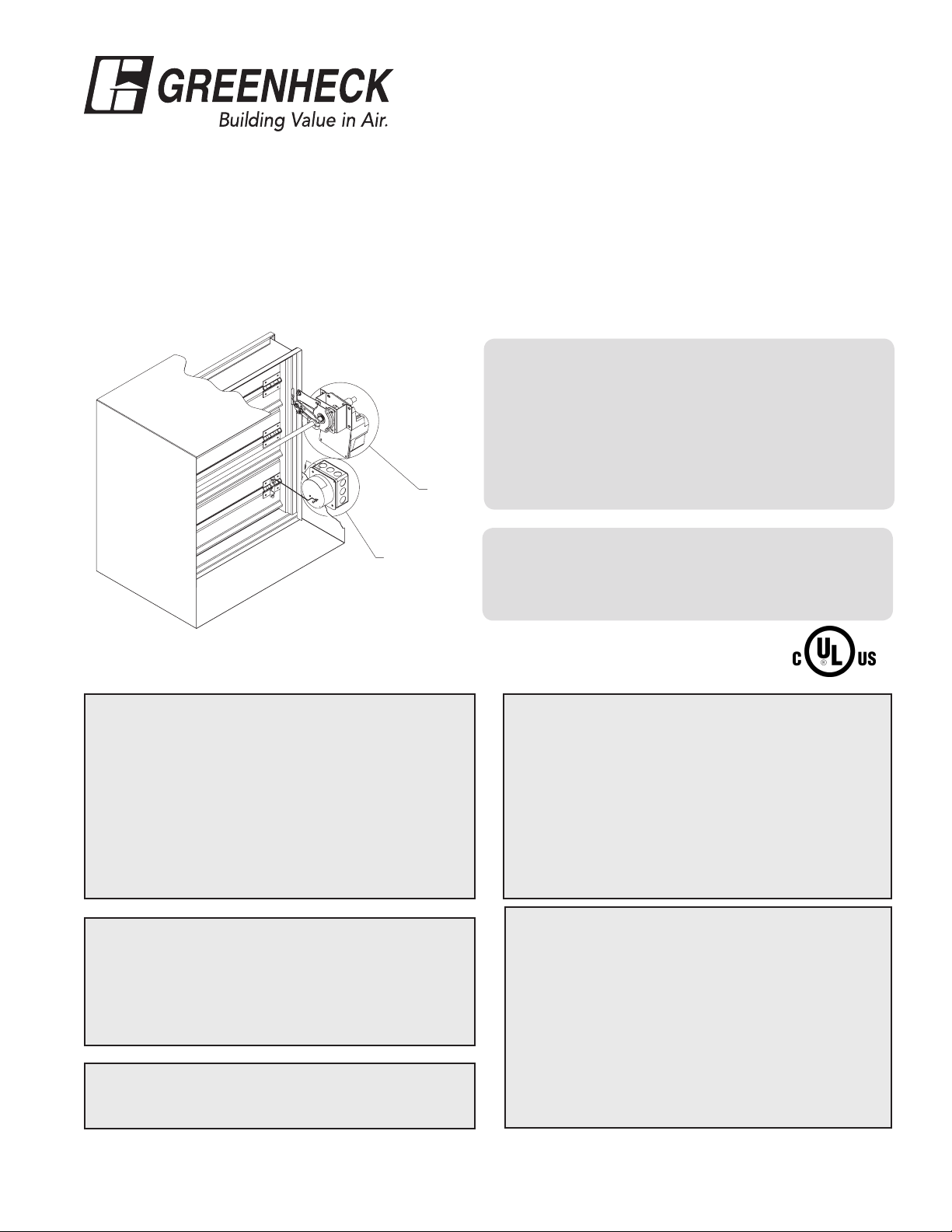
Typical Actuato
OCI Blade Indicator
(optional)
California State Fire Marshal (Listing #3230-0981:104)
“UL CLASSIFIED (see complete marking on product)”
“UL CLASSIFIED to Canadian safety standards (see
complete marking on product)”
UL Standard 555S (Classification #R13317)
Receiving and Handling
Upon receiving dampers, check for both obvious and
hidden damage. If damage is found, record all necessary
information on the bill of lading and file a claim with
the final carrier. Check to be sure that all parts of the
shipment, including accessories, are accounted for.
Dampers must be kept dry and clean. Indoor storage
and protection from dirt, dust and the weather is highly
recommended. Do not store at temperatures in excess of
100°F (38°C).
Safety Warning:
Improper installation, adjustment, alteration, service
or maintenance can cause property damage, injury or
death. Read the installation, operating, and maintenance
instructions thoroughly before installing or servicing this
equipment.
This manual is the property of the owner, and is required
for future maintenance. Please leave it with the owner
when the job is complete.
Due to continuing research, Greenheck reserves the right to change specifications without notice.
Refer to the appropriate Greenheck installation
supplements for special requirements:
• Smoke Detector Supplement (463813)
• No Flow Duct Smoke Detector (465915)
• Drive Slip Breakaway Supplement (468769)
• Quick Connect Breakaway Supplement
• Open or Close Indicator Supplement (459656)
• Double Flange Mounted Supplement (472664)
Greenheck warrants this equipment to be free from
defects in material and workmanship for a period of one
year from the shipment date. Any units or parts which
prove to be defective during the warranty period will be
repaired or replaced at our option. Greenheck shall not
be liable for damages resulting from misapplication or
misuse of its products. Greenheck will not be responsible
for any installation or removal costs. Greenheck will not
be responsible for any service work or backcharges
without prior written authorization.
Installation Supplements
(468502)
Warranty
Page 2
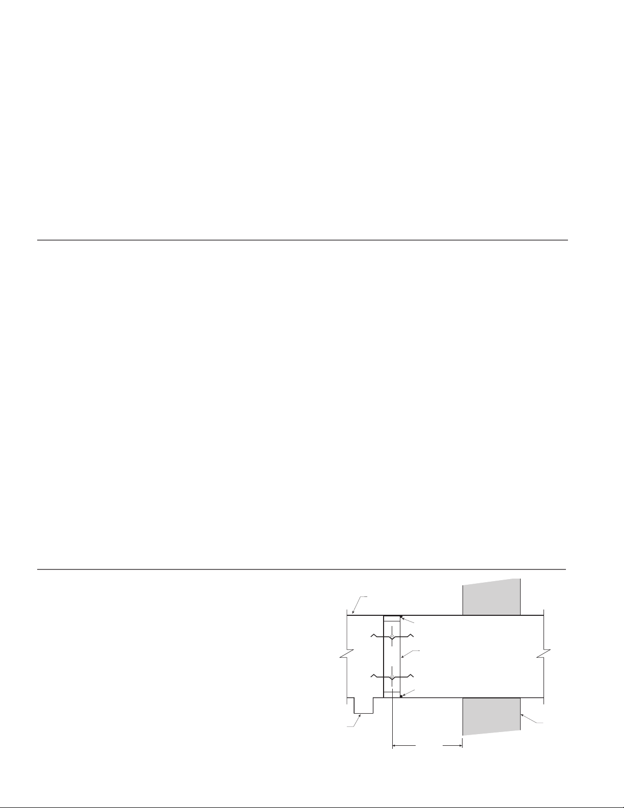
Table of Contents
24 in.
Ductwork
Duct Outlet
Smoke
Barrier
Sealant
Damper
Sealant
Pre-Installation Guidelines .............................................................................................................................................2
Installation .....................................................................................................................................................................3
• Smoke Damper Requirements ....................................................................................................................................3
• Location of Damper in Ductwork ..............................................................................................................................3
• Attaching Damper to the Duct ...................................................................................................................................3
• Installing Multiple Damper Section Assemblies .......................................................................................................3
• Sealing the Installation ................................................................................................................................................3
• Actuator Connections .................................................................................................................................................3
• Connection and Operation of Open/Close Indicator .................................................................................................3
SMDR-XXX and SSSMDR Blade Orientation................................................................................................................4
Maintenance ...................................................................................................................................................................4
Troubleshooting ..............................................................................................................................................................4
Pre-Installation Guidelines
The basic intent of a proper installation is to secure the smoke damper in, not to, the opening or duct in such a manner as
to prevent distortion and disruption of damper operation. The following items will aid in completing the damper installation
in a timely and effective manner.
1) Lift or handle damper using sleeve or frame. Do not lift damper using blades or actuators.
2) Damper (rectangular) has label on outside of sleeve indicating a ‘No Screw’ area. Do not install screws into this
area as screws may interfere with unexposed blade linkage and prevent damper blades from opening and/or
closing.
3) Damper must be installed into duct or opening square (round) and free of twist or other misalignment. Damper
must not be squeezed or stretched into duct or opening. Out of square, out of round, racked, twisted or
misaligned installations can cause excessive leakage and/or torque requirements to exceed damper/actuator
design.
4) Damper and actuator must be kept clean and protected from dirt, dust and other foreign materials prior to and
after installation. Examples of such foreign materials include but are not limited to:
a) Mortar dust
b) Drywall dust
c) Firesafing materials
d) Wall texture
e) Paint overspray
5) Damper should be sufficiently covered as to prevent overspray if wall texturing or spray painting will be
performed within 5 feet of the damper. Excessive dirt or foreign material deposits on damper can cause
excessive leakage and/or torque requirements to exceed damper/actuator design.
6) Caulking is not necessary, however, may be applied to optional retaining angles.
7) The Code Authority Having Jurisdiction (AHJ) must evaluate and provide approval of final installation where
variations to these instructions are necessary.
Installation - Failure to follow these instructions will void all warranties.
1. SMOKE DAMPER REQUIREMENTS
Smoke dampers are required to close and prevent the
passage of air and smoke through ducts or ventilation
openings in smoke barriers. Smoke dampers are also
applied in engineered smoke control systems to establish
air pressure differentials and thereby prevent the spread of
smoke.
2. LOCATION OF DAMPER IN DUCTWORK
Place the damper assembly in its proper position relative
to the barrier as shown (in Figure 1). The plane of the
closed damper blades must be within 24 in. (610mm) of
the rated smoke barrier and before any duct inlets or
outlets.
2
Fig. 1
Page 3

3. ATTACHING DAMPER TO THE DUCT
Attach the damper to the duct using #10 sheet metal
screws, 1/4 in. (6mm) diameter bolts and nuts, tack or
spot welds, or 3/16 in. (5mm) diameter steel pop rivets.
Attachments must be made at each flange spaced a
maximum of 6 in. (152mm) on centers and a maximum of
2 in. (51mm) from corners on rectangular dampers, and on
round dampers as follows: Ducts 22 in. (559mm) in diameter
and smaller shall have three attachments. Ducts larger
than 22 in. (559mm) in diameter up to and including 36 in.,
(914mm) have five attachments.
4. INSTALLING MULTIPLE DAMPER SECTION
ASSEMBLIES
The damper assembly is not restricted to a maximum
number of sections, but must not exceed the section sizes
and assembly sizes shown below.
6. ACTUATOR CONNECTIONS
Electrical and/or pneumatic connections to damper
actuators should be made in accordance with wiring and
piping diagrams developed in compliance with applicable
codes, ordinances and regulations.
7. CONNECTION AND OPERATION OF OPEN/CLOSE
INDICATOR
OCI - The OCI (open or closed indicator) option contains
a single pole, double throw switch used to indicate
the damper blade position. The switch provides
a positive open or closed signal when used in
conjunction with remote indicator lights. Refer to Fig.
2 for wiring of the OCI option.
Damper model
SMD-201, 202,
203
SMD-201M, 202M 36 x 36
SMD-301, 302
SMD-301M, 302M
SMD-401
SMDR, SESMDR,
SSSMDR
SESMD-201,
SSSMD-201
SMD-301V
SMD-401M
Maximum Single
Section Size
in. (mm)
36 x 48 or 32 x 50
(914 x 1219 or
813 x 1270)
32 x 50
(813 x 1270)
32 x 50
(813 x 1270)
48 x 60
(1219 x 7315)
24
(610)
24 x 30
(610 x 762)
50 x 32
(1270 x 813)
36 x 36
(914 x 914)
Maximum Overall
Size for Multiple
Section Dampers
in. (mm)
144 x 100 or 288 x 50
(3658 x 2540 or
7315 x 1270)
144 x 72 or 288 x 36
(3658 x 1829 or
7315 x 914)
128 x 100 or 256 x 50
(3251 x 2540) or
(6502 x 1270)
128 x 100 or 256 x 50
(3251 x 2540) or
(6502 x 1270)
192 x 120, 48 x 288,
or 384 x 36
(4877 x 1829,
1219 x 7315 or
9754 x 914)
NA
88 x 72
(2235 x 1829)
100 x 32
(2540 x 813)
144 x 72 or 288 x 36
(3658 x 1829 or
7315 x 914)
Fig. 2 OCI Wiring
RATINGS
Integral Switch Type: Single Pole, double throw
Electrical: 10 Amps, 1/3 hp, 120 or 240 Vac
1/2 Amp, 120 Vdc; 1/4 Amp 240 Vdc
5 Amps, 120 Vac “L” (lamp load)
1.0 Amps, 24 Vac
1.5 Amps, 24 Vdc
SMDR-XXX and SSSMDR-XXX Blade
Orientation
Axle
30°
The damper sections must be attached together with #10
sheet metal screws, 1/4 in. (6mm) diameter nuts and bolts,
1
/2 in. (13mm) long welds, or 3/16 in. (5mm) diameter steel
pop rivets.
On multiple section damper assemblies, the temperature
rating of wiring run in the airstream shall be at least equal to
the damper temperature rating plus 50°F (10°C).
5. SEALING THE INSTALLATION
After installing the damper in the ductwork, seal the joint
between the damper frame and the duct using Dow Corning
RTV 732 sealant, GE1200 series silicone construction
adhesive or Component Hardware SLT-5000 silicone
sealant. Make sure to press the sealant into the joint to
guarantee a proper seal. Use the minimum amount of
material required to completely seal the joint. See Figure 1.
Axle
30° Off Horizontal
(Maximum)
30° Off Horizontal
(Maximum)
30°
3
Page 4

Damper Maintenance
Dampers do not typically require maintenance as long as
they are kept dry and clean. If cleaning is necessary, use
mild detergents or solvents. If lubrication is desired for
components such as axle bearings, jackshaft bearings and
jamb seals, do not use oil-based lubricants or any other
lubricants that attract contaminants such as dust.
Damper actuator(s) must be maintained, cycled, and tested
Axle
Normal
in accordance with:
• The latest editions of NFPA 90A, 92A, 92B, 105, UL864,
AMCA 503-03 and local codes.
• Actuator manufacturer recommendations.
Damper Troubleshooting
The following is a possible cause and correction list for common concerns with the dampers.
Sympton Possible Cause Corrective Action
Damper does not fully
open and/or close
RRL or TOR sensor
tripped
Damper does not
operate
Frame is 'racked' causing blades to bind
on jamb seals
Actuator linkage loose Close damper, disconnect power, adjust and tighten
Defective motor Replace
Screws in damper linkage Damper installed too far into wall. Move out to line as
Contaminants on damper Clean with a non-oil based solvent (see Damper
Heat Push reset button located on backside of RRL or TOR
No power supplied to the actuator Add power supply
Adjust frame such that it is square and plumb
linkage
designated on damper label
Maintenance)
Our Commitment
As a result of our commitment to continuous improvement, Greenheck reserves the right to change
specifications without notice.
Specific Greenheck product warranties are located on greenheck.com within the product area tabs and in
the Library under Warranties.
®
Phone: (715) 359-6171 • Fax: (715) 355-2399 • E-mail: gfcinfo@greenheck.com • Website: www.greenheck.com
461338• Smoke Dampers IOM Rev. 14, November 2014 Copyright 2014 © Greenheck Fan Corporation
4
 Loading...