

Page 1
The
High
Performance
Company
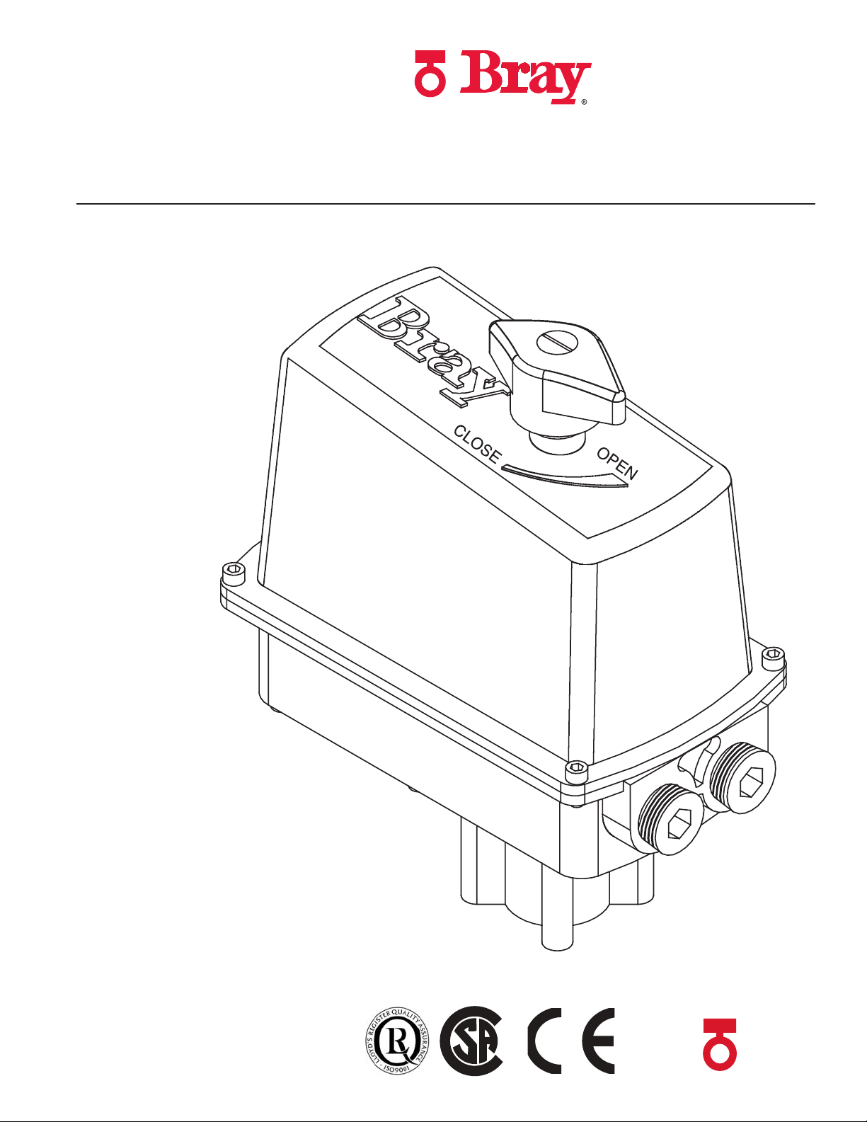
SERIES 73
ELECTRIC ACTUATOR
OPERATION AND MAINTENANCE MANUAL
Page 2

Page 3

Table Of COnTenTs:
page
Safety inStructionS: DefinitionS of termS................................................................. 2
introDuction
principle of operation.............................................................................................. 3
electrical operation................................................................................................ 3
mechanical operation.............................................................................................. 3
inStallation
pre-inStallation Storage......................................................................................... 3
mounting to valve.................................................................................................... 4
manual overriDe operation..................................................................................... 4
electrical inStallation............................................................. .............................. 5
multiple actuator wiring......................................................................................... 6/7
travel limit Switch aDjuStment............................................................................... 8
fielD or factory inStallable optionS
heater........................................................................................................................ 8
auxiliary SwitcheS.................................................................................................... 9
typical Single phaSe & Dc wiring DiagramS.......................................................... 10
appenDix a
baSic toolS................................................................................................................ 11
appenDix b
actuator troubleShooting chart........................................................................... 12
for information on thiS proDuct anD other bray proDuctS
pleaSe viSit uS at our webpage - www.bray.com
Page 4
BRAY Series 73 Electric Actuator
!
!
!
Operation and Maintenance Manual
1.0 safeTy InfOrmaTIOn - DefInITIOn Of Terms
WARNING indicates a potentially hazardous situation which, if not avoided, could
result in death or serious injury.
CAUTION indicates a potentially hazardous situation which, if not avoided, may
result in minor or moderate injury.
NOTICE used without the safety alert symbol indicates a potential situation which,
if not avoided, may result in an undesirable result or state, including
property damage.
1.1 HazarD-free use
This device left the factory in proper condition to be safely
installed and operated in a hazard-free manner. The notes
and warnings in this document must be observed by the
user if this safe condition is to be maintained and hazardfree operation of the device assured.
Take all necessary precautions to prevent damage to the
actuator due to rough handling, impact, or improper storage.
Do not use abrasive compounds to clean the actuator, or
scrape metal surfaces with any objects.
ground, tag and lock electrical circuits and equipment in
• accordance with established safety practices
• Is trained in the proper use and care of personal pro-
tective equipment (PPE) in accordance with established
safety practices
• Is trained in rst aid
• In cases where the device is installed in a potentially
explosive (hazardous) location – is trained in the operation, commissioning, operation and maintenance of
equipment in hazardous locations
The control systems in which the actuator is installed
must have proper safeguards to prevent injury to personnel, or damage to equipment, should failure of system
components occur.
1.2 QualIfIeD PersOnel
A qualied person in terms of this document is one who is
familiar with the installation, commissioning and operation of
the device and who has appropriate qualications, such as:
• Is trained in the operation and maintenance of electric
equipment and systems in accordance with established
safety practices
• Is trained or authorized to energize, de-energize,
2
WARNING
The actuator must only be installed, commissioned, oper-
ated and repaired by qualied personnel.
The device generates large mechanical force during normal
operation.
All installation, commissioning, operation and maintenance
must be performed under strict observation of all applicable
codes, standards and safety regulations.
Reference is specically made here to observe all applicable safety regulations for actuators installed in potentially
explosive (hazardous) locations.
Page 5
BRAY Series 73 Electric Actuator
Operation and Maintenance Manual
Part nuMbering systeM reference chart
Part nuMber tOrque sPeed, 1/4 turn suPPly suPPly
(In.Lbs) (Seconds) (Volts AC) (Volts DC)
73-010Y-113ZV-536 100 2/5/10 120/240 NA
73-030Y-113ZV-536 300 5/10/15 120/240 12/24
73-060Y-113ZV-536 600 5/10/15/30/60 120/240 12/24
Y - DESIGNATES THE SPEED S
Y = 0 1 2 3 4 5
SEC = 2 5 10 15 30 60
Z - DESIGNATES DRIVE TYPE
Z=
TYPE=
Use this chart as a guide to interpret the S73 electric actuator part number.
D S
DOUBLE D STAR
InTrODuCTIOn
The Bray Series 73 is a quarter turn electric actuator with
manual override for use on any quarter turn valve requiring
up to 600 Lb-In of torque. Operating speeds vary between
2 to 60 seconds. Adjusting two cams sets the open and
close travel limit switches. These cams can be adjusted to
allow rotational travel anywhere from 45° to 300°. Standard
Factory setting allows for 90° reversible rotation.
PrinciPle Of OPeratiOn
The Series 73 actuator is basically divided into two internal
sections; the power center below the switchplate, and the
control center above the switchplate. Below the switchplate the spur geartrain drives an output coupling. The
override mechanism for manual operation is also located
here. Above the switchplate are components requiring
customer adjustment. The indicator shaft assembly, limit
switches, terminal strips, heater, capacitor and motor are
all placed here for easy access. External to the unit are a
highly visible valve position indicator, the unique manual
override shaft and two 1/2” NPT conduit entry ports. The
external nish is a high quality polyester powder coating,
which has exceptional UV as well as chemical resistance.
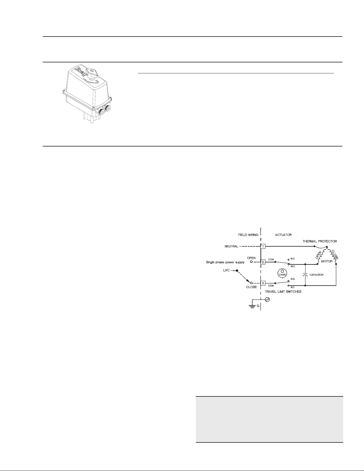
electrical OPeratiOn
The motor used in the Bray Series 73 is a permanent
induction split capacitor design (single phase AC power).
Travel limit switches are mechanical form C (SPDT) are
rated at 10 amp (0.8 PF), 1/2 HP 125 VAC and 3/4 HP
250 VAC. In situations where the torque capacity of the
unit is exceeded to the point where the motor stalls and
overheats, a thermal protector switch built into the motor
windings will automatically disconnect the motor power.
Once the motor cools sufciently the thermal switch will
V - DESIGNATES VOLTAGE
V=
VOLTAGE
3 4 5 6
12VDC 24VDC 120VAC 220VAC
reset. The motor has a spring loaded brake that activates
when power is removed from the unit. The brake prevents
the spur gears from being back driven.
General Electrical Schematic
(Note: the schematic below is for reference only. The actual wiring
diagram for each specic unit is placed inside the actuator cover).
Mechanical OPeratiOn
Mechanically, the ratio of the gearmotor determines the
speed of the unit. The gearmotor utilizes high efciency
spur gears with various ratios for the actuation speeds.
Positioning is determined by an indicator-camshaft linked
to the output coupling.
Pre-installatiOn stOrage
Units are shipped with two metal conduit entry plugs to
prevent foreign matter from entering the unit.
nOTICe
To prevent condensation from forming inside these units,
maintain a near constant external temperature and supply power to the optional heater internal to the unit.
3
Page 6

Open Travel
Switch
Close Travel
Switch
Gear With
Square
Drive Hole
(Cutaway)
Switch Plate
(Cutaway)
Spring
Valve Stem
Gear With
Square
Drive Hole
(Cutaway)
Switch Plate
(Cutaway)
Double D Drive End
of Indicator Shaft
Actuator Drive
Coupling
Valve Stem
Double D Drive End
of Indicator Shaft
Actuator Drive
Coupling
Indicator Shaft
Spring
Snap Ring
Open Travel
Switch
Close Travel
Switch
Open Cam
Close Cam
Square Drive
of Indicator
Shaft
Square Drive
of Indicator
Shaft
Snap Ring
Indicator Shaft
Using an Adjustable
Wrench, Push Down
and Rotate the Indicator
Shaft to Manually Drive
the Actuator & Valve
Series 73 Under Normal
Electrical Operating
Conditions
Open Cam
Close Cam
BRAY Series 73 Electric Actuator
!
Operation and Maintenance Manual
WARNING Turn off all power and lock out service panel before installing or modifying any
electrical wiring.
InsTallaTIOn
MOunting tO a ValVe
All Bray Series 73 electric actuators mount directly to Bray
buttery valves. With proper mounting hardware, the S73
actuator can be installed onto other quarter-turn valves or
devices. For horizontal installation, the standard mounting position aligns the actuator parallel and upright to the
pipeline. If the actuator is to be mounted on a vertical
pipe, it is recommended that the unit be positioned with
the conduit entries on the bottom to prevent condensation from entering the actuator through the conduit. In
all cases, the conduit should be positioned to prevent
drainage into the actuator.
manual OverrIDe OPeraTIOn
1. Ensure that electrical power to the unit is off.
2. Press valve position indicator down, then release a
few times to ensure ease of movement.
3. Remove the valve position indicator pointer.
4. Using an adjustable wrench, 6” or 12” depending
on actuator size, push down on indicator shaft to
disengage it from output gear, then turn shaft to
required position. Open and Close lettering and a
The actuator should be mounted to the valve as follows:
1. Manually operate the actuator until the output shaft of
the actuator is in line with the valve stem. If possible,
use an intermediate position (i.e. valve disc/stem and
actuator half open).
2. Place the proper adapter, if required, onto the valve
stem. It is recommended that a small amount of grease
be applied to the adapter to ease assembly.
3. Mount the actuator onto the valve stem. It may be
necessary to manually override the actuator to align
the bolt patterns.
4. Install the furnished mounting studs by threading
them all the way into the actuator base.
5. Fasten in place with the furnished hex nuts and lock
washers.
direction of travel arrow are molded into the housing for easy reference and permanent position
indication. The double D ats on the indicator shaft
are in alignment with the valve disc position.
5. Return to electrical operation by turning power
on to the unit. The shaft will re-engage the
output gear when electrical power is applied to
the actuator.
6. Replace the valve position indicator pointer.
4
Page 7

electrical installatiOn
SERIES
73
TORQUE
VOLTAGE
SPEED
[N m]
In. lbs.
TAG
sec.
DUTYF.L.C.
XXX
INT.O.4
120VAC
100 10
Amps
1 /4
turn
C US
!
!
1. Check the actuator’s nametag for conrmation of:
Torque Rating, Quarter Turn Time, Duty Rating and
Power Supply. Example ‘A’ below is shown for S73
PN: 73-0102-113D5-536
2. Suitably rated wire should be used for actuator voltage
and current rating. 18AWG, 300V minimum, insulated
wire is recommended for all sizes.
3. Field control scheme (supplied by others) should be
compatible with the operation of actuator motor (AC
or DC).
NOTE: Do not parallel wire multiple actuators - refer
to explanation on parallel wiring.
CAUTION
Do not reverse motor instantaneously when it is still
running - Reversing direction to actuator motor when
it is running can cause damage to motor, switches and
gearing. Directional control switching can be done by
PLC in 20ms or by a small relay in 45ms. Therefore
time delay of 1s has to be incorporated into the control
scheme to avoid damage.
NOTICE
BRAY Series 73 Electric Actuator
Operation and Maintenance Manual
CAUTION
Do not reverse motor instantaneously when it is still
running - Reversing direction to actuator motor when
it is running can cause damage to motor, switches and
gearing. Directional control switching can be done by
PLC in 20ms or by a small relay in 45ms. Therefore
time delay of 1s has to be incorporated into the control
scheme to avoid damage.
Figure A
Correct
18 AWG minimum wire is recommended for all eld wiring
4. Actuator must have its eld wiring terminated as shown
in the supplied wiring diagram (diagram attached to
inside of cover). Wiring diagrams (AC or DC) show
remote (customer supplied) typical control switching
devices. Refer to customers/eld wiring for details of
the specic control devices.
The conduit connections must be properly sealed to maintain the weatherproof integrity of the actuator enclosure.
Example A:
NOTICE
Incorrect
5
Page 8

BRAY Series 73 Electric Actuator
Operation and Maintenance Manual
Multiple Actuator (Parallel) Wiring
A voltage is present on both motor windings, these voltages
are out of phase and different in magnitude. If these windings
are connected to one another as shown in the INCORRECT
diagrams, this will interfere with the motor performance. Use
a multiple pole switch as shown in the CORRECT diagram.
incOrrect cOnnectiOns
A. No supply on terminal L.
B. Control switch in “Open Run Position”
C. Both actuators in a mid-travel position. i.e. Their open
& close travel switches are closed, allowing them to
operate in an open or close travel direction.
*The following three diagrams show progressive
result of parallel wiring.
D. 120VAC source applied, both motors start to run “open”.
(Shows current ow)
E. #1 actuator runs fully open and its travel limit switch
opens circuit. This actuator stops (perhaps only for a
short time!). #2 actuator continues to run open.
(Shows current ow)
F. The other “Back Feeding” current path existing between
the actuators is shown.
G. Though actuator #1 had come to rest (full open), it can
and does get current owing through its close travel leg
via this “Back Feeding” current from #2 actuator.
This causes actuator #1 to run a couple of degrees in the
closed direction, #2 actuator will then reach its fully open
position. If left running for a “good” period, both actuators end
up driving each other OPEN-CLOSED at strange positions.
(Shows current ow)
(Shows other “Back Feeding” current ow)
6
Page 9

cOrrect cOnnectiOns
To eliminate this “BACK FEEDING PARALLEL” driving, we suggest separate contacts for each actuator.
BRAY Series 73 Electric Actuator
Operation and Maintenance Manual
If we redraw the diagram for the #1 actuator having
reached its fully open travel position and having tripped
its open travel limit switch. You can see that the #2
actuator would still run on, until it reached its fully open
position. The #2 actuator when running open can not
“BACK FEED”, the rst actuator’s closed travel motor
winding (as it did in G). on the previous page).
(Shows current ow)
7
Page 10

BRAY Series 73 Electric Actuator
!
!
Operation and Maintenance Manual
traVel liMit switch caM adjustMent
Each cam has two tapped holes with one setscrew that
may be placed at either location for easy access.
Cams are innitely adjustable by using a 5/64” hex key.
Standard factory setting allows for 90 degrees reversible
rotation between open and close positions.
The bottom of the cam must be aligned with the bottom of
the travel limit switch button to allow the switch to function
properly during manual override.
Correct positioning of cam & switch are shown in the illustration below, when in motor/automatic drive condition.
heater
To prevent condensation from forming inside the actuator,
Bray offers an optional heater. The heater is a PTC (Posi-
tive Temperature Coefcient) type, which has a unique
temperature - resistance characteristic. The heater selfregulates by increasing its electrical resistance relative
to its temperature. The heater does not require external
thermostats or switches to control its heat output. It is
constructed of a polycrystalline ceramic, sandwiched
between two conductors, and wrapped inside a thermally
conductive electrical insulator.
Connect the heater wires to the terminal strip as indicated
on the wiring diagram.
heater Kit cOnsists Of:
1. Heater with ying leads
2. Heater Mounting Bracket
3. #10 pan head screw, phillips drive
tOOls required:
• For terminal wiring Screwdriver, 3/16” tip at blade
• For heater mounting screw Screwdriver, No.1 phillips
installatiOn PrOcedure:
WARNING
Turn off all power and lock out service panel before
installing or modifying any electrical wiring.
The heater is mounted through a hole provided in the
switchplate.
1. Place the heater snugly into its mounting bracket
until approx. 1/2” is below the bracket as shown in
the illustration below.
2. Slip the heater into its mounting hole
3. Align the fastening hole in the bracket with the
threaded screw hole in the plate. Fasten the heater
to the switchplate.
4. Connect the heater wires to the terminal strip as
indicated on the wiring diagram.
WARNING
The heater surface can reach temperatures in excess
of 200 degrees Celsius.
8
Page 11

BRAY Series 73 Electric Actuator
Operation and Maintenance Manual
field install. Of auxiliary switch (es)
The maximum allowable auxiliary switch conguration is
shown in the illustrations below for each size of actuator.
auxiliary switch Kit cOnsists Of:
1. Switch with ying leads
2. Switch spacers
3. Cam with set screw
4. Cam spacers
5. Pan head screw, phillips drive
tOOls required
For terminal wiring Screwdriver, 3/16” at tip blade
installatiOn PrOcedure:
For switch mounting Screwdriver, No. 1 phillips
1. Remove switch mounting screws & discard
2. Remove switch bracket & retain for use later
3. Install auxiliary cam(s) and spacers as shown
4. Install auxiliary switch(es) and spacers as shown
5. Reinstall switch bracket
6. Install longer switch mounting screws from kit
7. Connect switch wiring to terminal strip per wiring
diagram
8. Adjust cams as required
9
Page 12

BRAY Series 73 Electric Actuator
Operation and Maintenance Manual
Typical actuator wiring diagrams shown for single phase A.C. and D.C. motorized units.
Diagrams show actuators in their fully closed positions.
10
Page 13

BRAY Series 73 Electric Actuator
Operation and Maintenance Manual
aPPenDIx a
basic tOOls required fOr installatiOn
cOMMOn tO all units
Position Indicator Knob Screwdriver, 3/4” tip at
All switches, heater kit Screwdriver, No.1 phillips
Terminal strip wiring Screwdriver, 3/16” at tip
Cam adjustment Hex key, 5/64”
Cover socket head cap screws Hex key, 9/64”
100-300 lb-in units
Switchplate socket head cap screws Hex key, 9/64”
Valve mounting nuts (small bolt circle) Wrench, 3/8”
Valve mounting nuts (large bolt circle) Wrench, 7/16”
600 lb-in units
Switchplate socket head cap screws Hex key, 7/64”
Valve mounting nuts (small bolt circle) Wrench, 7/16”
Valve mounting nuts (large bolt circle) Wrench, 1/2”
11
Page 14

BRAY Series 73 Electric Actuator
Operation and Maintenance Manual
aPPenDIx b
actuatOr trOubleshOOting chart
Problem Possible cause Solutions
Actuator does not operate Cams are depressing travel switch Adjust cams to their correct positions
Override is engaged/shaft depressed Apply electricity to cancel manual
mode
Wiring is incorrect Check wiring and power supply
Actuator has reached its thermal Allow time to cool
shutdown temperature
Actuator operates in reverse Field wiring is reversed Rewire eld wiring
directions
Actuator does not fully close valve Limit switches are tripping Readjust travel limit switches
(or open valve) Valve torque requirement is higher Manually override out of seat, try
than actuator output angle seating or t larger actuator
Voltage power supply is low Check power source
Motor hums but does not run Motor brake engaged Check that brake is not obstructed
Corrosion inside unit Condensation forming Test heater wiring, should have
constant power supply
Water leaking into the unit Check all seals and possible water
entry through conduit
12
Page 15

nOTes
BRAY Series 73 Electric Actuator
Operation and Maintenance Manual
13
Page 16

A Division of BRAY INTERNATIONAL, Inc.
13333 Westland East Blvd. Houston, Texas 77041
281.894.5454 FAX 281.894.9499 www.bray.com
Bray® is a registered trademark of BRAY INTERNATIONAL, Inc.
© 2009 Bray International. All rights reserved. OM-73-001 12-2009
 Loading...