

Page 1
R
™
4
Red
Round
Rotary
Reliable
Electric Actuator
Page 2
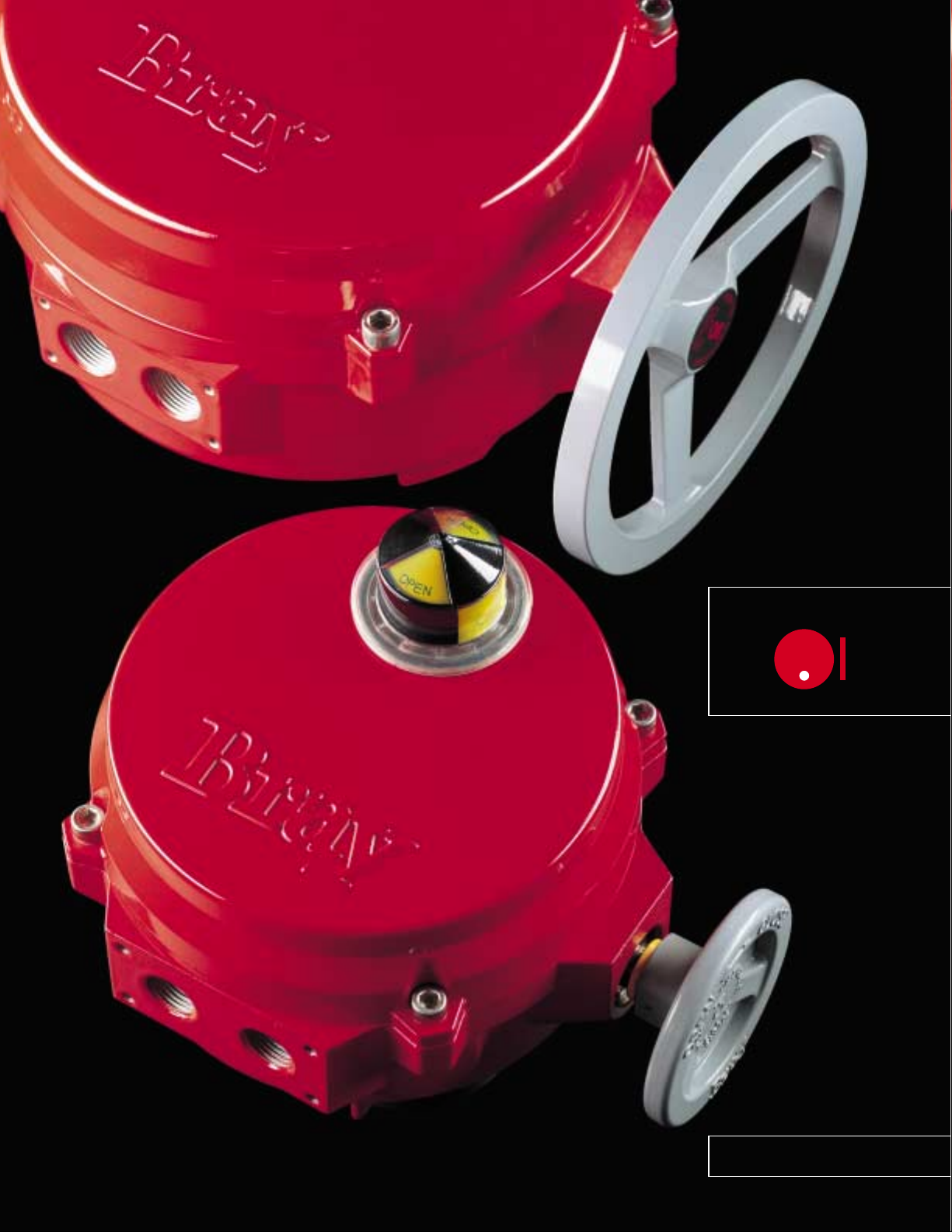
RUGGED ELECTRIC
ACTUATOR FOR
ROTARY VALVES
300 TO 6,500 LB-IN
OUTPUT TORQUE
Bray Controls’ years
of proven success in
electric actuation,
combined with inno-
SERIES 70
trol. This red, round electric
actuator for rotary valves
delivers highly reliable service.
vative engineering,
has produced the R4.
The R4 features on-off
or modulating con-
™
™
4
R
Bray’s unique, customer–friendly
designed Control Center has
many advantages over present
industry standards including:
• UL, CSA and CE certification of
most units
• Ease of customer field wiring
directly to the terminal strip
without interference from
other components
• Simple and unique manual
override handwheel system
• Lowest profile and lightest
weight actuator on the market
• Simple finger or screw driver
adjustment of travel limit
cams without interference
from other components
• Highly visible valve status
display
• Externally adjustable travel
stops
• Captive housing screws
Additionally, components not
requiring customer access are
protected underneath the Power
Center cover plate.
Red
Round
Rotary
Reliable
LOW PROFILE, COMPACT,
HIGH TORQUE DESIGN
The R4 is by far the most compact,
lowest profile design of any electric
actuator delivering comparable torque
output. Thorough research and many
years of field experience have gone
into the development of this stateof-the-art actuator – the product of
the future. This design offers the
advantages of greatly reduced space
requirements, lighter weight and ease
of installation and maintenance when
compared to other electric actuators.
When mounted directly to Bray valves,
4
is especially compact.
the R
The Bray
4
R
Electric
Actuator
4
compared to a typical actuator,
The R
both mounted to 4" Bray valves.
DIRECT MOUNTING OF THE R
ON BRAY VALVES
Bray actuators mount directly to Bray
valves without using any external
linkage. Field installation is simple
and misalignment is minimized. For
sanitary processing and outdoor
applications, the Bray direct mounting system reduces the possibility
of contamination buildup or corrosion between the valve and actuator.
The mounting pattern complies with
ISO 5211 and VDI/VDE 3845 (NAMUR
recommendations). The R
mounted and operated in any
position. Standard rotation is 90°
reversible. Bray can provide linkages
for mounting the R
requiring 90° rotation. Please consult
the Bray factory for further information.
4
can be
4
to other devices
4
EXTERIOR FEATURES
EXPLOSION PROOF ENCLOSURE
The R4 waterproof/explosion proof unit
is UL NEMA 4,4x,7&9 listed and certified to specifications for hazardous
locations. This rugged, heavy duty
housing contains precision machined
bores and flanges to meet flame path
requirements. The valve position
indicator is viewed from behind a
sodium glass explosion proof window.
This unit is currently available with
800 to 2,000 lb.-in. output torque,
continuous or intermittent duty.
MECHANICAL TRAVEL STOPS
Stainless steel mechanical travel
stops permit precise field adjustment
of actuator movement to specific
degrees of rotation. The travel stops
are located outside the base for easy
readjustment without removing the
cover. Stainless steel lock nuts with
O-ring seals hold the travel stops
securely in place. The travel stops
are normally set at the factory to
allow 0° and 90° travel.
R4 manual override handwheel
with optional spinner.
2
Page 3
ENCLOSURE (A)
The R4 waterproof unit is UL NEMA 4, 4x
listed. Die-cast aluminum cover and base
are high-quality polyester powder
coated for exceptional corrosion, wear,
impact and ultra-violet resistance. Potential leak paths are eliminated since the
indicator shaft does not protrude
through the enclosure.
MANUAL OVERRIDE (B)
A manual override handwheel is standard on all models to rotate the valve
without electrical power. A yellow
caution stripe around the handwheel
hub indicates the handwheel is engaged
for manual operation.
CAPTIVE COVER BOLTS (C)
The cover is attached to the base by stainless steel bolts. When the cover is removed
the bolts are held captive in the cover.
This prevents time consuming problems
caused from lost or misplaced
bolts.
VALVE STATUS DISPLAY (D)
The R4 features a highly visible valve
status display. Prominently labeled and
color coded – yellow for open, red for
closed – the display indicates valve position through the full range of travel.
The display can be seen from almost
any angle. Made of high impact, heat
and chemical resistant clear polycarbonate, this display withstands caustic
washdown and offers excellent corrosion protection.
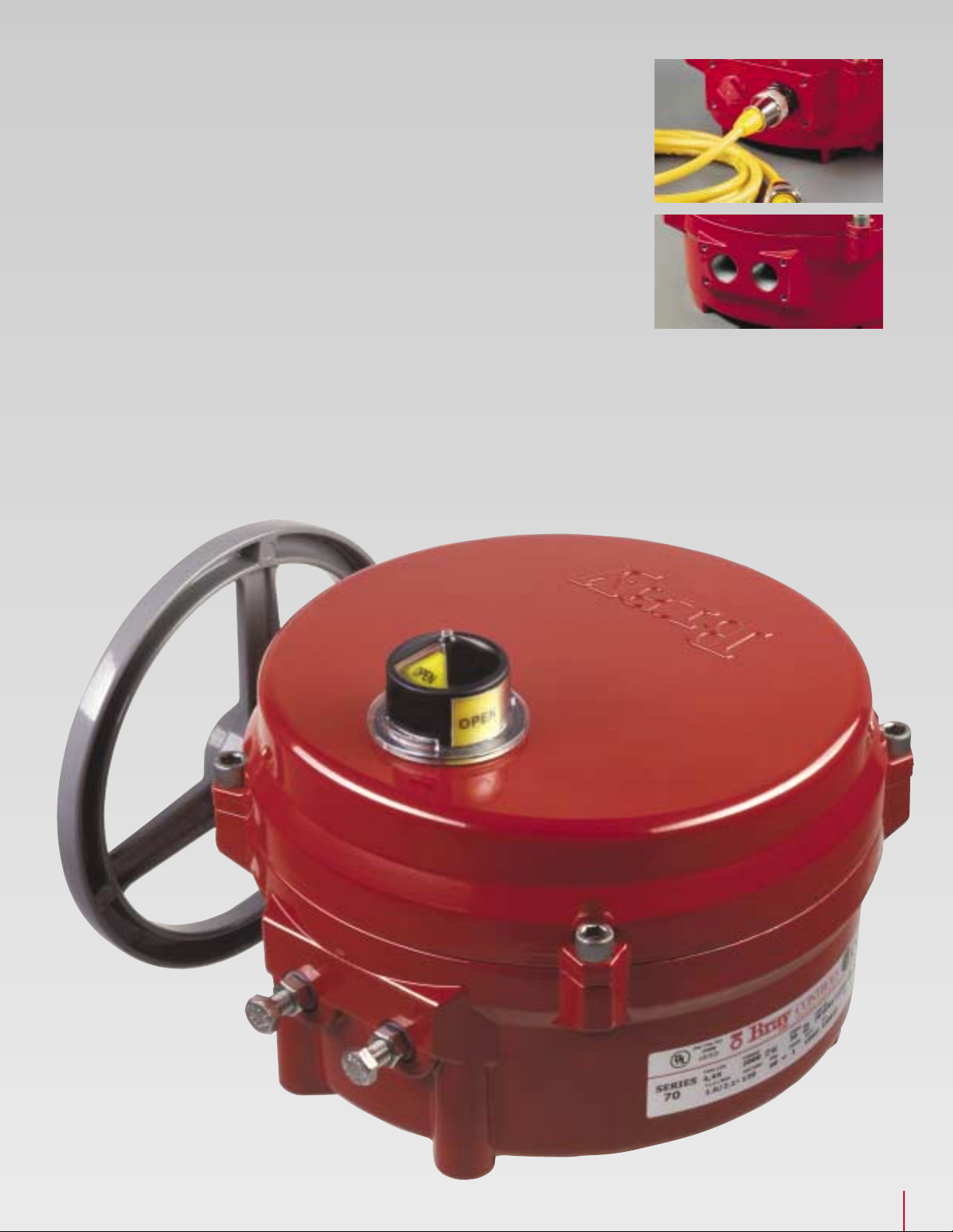
ELECTRICAL CABLE CONNECTIONS
(E) (Optional)
A multi-pin, watertight
cable receptacle offers full compatibility
with today’s industrial wiring systems.
Factory pre-wiring prevents errors and
allows quick–connect field installation.
Cordsets with connection/flying leads
or extension cords with connections on
both ends can plug directly into the
receptacle.
E
F
G
CONDUIT ENTRIES (F)
The R4 features two conduit connections
in either NPT or metric threads. One entry
is for power, one for control wiring.
PILOT DRILLED HOLES FOR LOCAL
CONTROL STATION MOUNTING (G)
The conduit entry panel has four holes
which may be easily tapped for the
installation of optional local
Control Station.
A
D
B
C
3
Page 4

CLEAN AND EASY
ACCESS TO ALL
FIELD WIRING AND
ADJUSTMENTS
Bray has specifically
engineered the R
Control Center for
customer–friendly
convenience. Designed
like a junction box,
4
the R
the easiest access to
terminal block wiring,
cam adjustments and
switch installation.
Accessories are easily
added, either before
installation or after
CONTROL CENTER
nance can be performed with
assured ease and safety.
Bray’s unique design, modular system of components and
accessories, and innovative
features combine to best meet
today’s industrial requirements.
installation. Therefore, the time required
for field start-up and
adjustment is greatly
reduced, and mainte-
offers by far
™
4
4
R
Red
Round
Rotary
Reliable
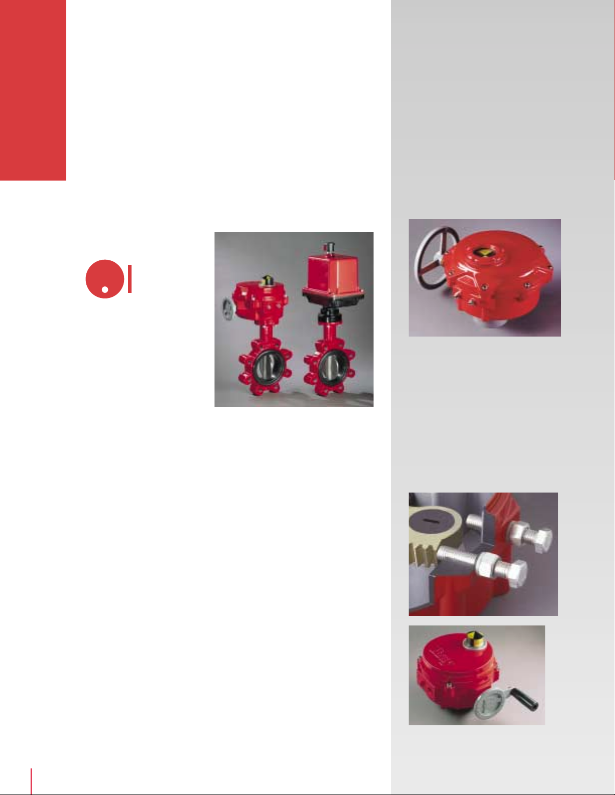
TORQUE LIMITING
SWITCHING SYSTEM (Optional)
The torque limiting switching system
consists of two SPDT mechanical
switches and two factory calibrated
adjusting screws. The green screw
adjusts the torque limit in the open
direction, and the red screw adjusts
the torque limit in the closed direction. The switches independently
respond to predetermined loads in
both the open and closed travel
directions by sensing the movement
of the worm shaft, and interrupting
the electrical power to the motor.
The switches operate at any point of
actuator travel.
Torque Limit Switches shown with
mounting bracket sectioned for clarity.
R4 APPLICATIONS
The R4 is the ideal choice for process
control applications involving:
• Automation and computer systems
• Butterfly, ball, plug and other
rotary valves
• Dampers, switches, safety and
flow-control devices
• Machine and fixture indexing
• Hostile environments demanding
excellent moisture, chemical and
corrosion resistance
• Long service life and rugged
reliability
INDUSTRIES
Bray’s R4 Electric Actuators are used
in a wide range of industries world
wide, including:
Chemical, Pharmaceutical, Petroleum
Refining and Oilfield, Microelectronics,
Pulp and Paper, Water and Waste
Water Treatment, Brewing, Food
Processing, Beverages, Power,
Marine, Mining, Textile and HVAC.
CONTROL CENTER
FEATURES
TRAVEL LIMIT SPDT SWITCHES
(A)
Bray has provided two SPDT
switches as standard. These durable,
high quality switches are mechanically isolated and electrically independent. The dedicated circuits eliminate
any voltage crossover between the
switches. This switch combination is
used for both open and closed
positions of the valve and requires
only one cam for each direction of
valve travel. Bray’s design provides
synchronicity between motor control
and position display. Switches are
easily accessible without interference
from other components. Each switch
is marked with open or close labels
and the cams are color coded, green
for open and red for close, eliminating the possibility of making wrong
adjustments of travel limits or field
wiring errors.
AUXILIARY SWITCHES (Optional)
Independent dry-contact SPDT
switches are available to indicate
travel position to remote customer
control systems.
AUTOMATIC POWER
CUTOUT SWITCH (B)
The R4 is supplied with a SPDT
mechanical switch which cuts power
to the motor when the handwheel
is engaged for manual operation.
This switch also functions as a safety
emergency shutdown device that
immediately stops the actuator motor
even if electrical power is still being
applied to the motor.
CERTIFICATIONS / APPROVALS
Bray has gained UL, CSA and CE
certifications on most intermittent
and continuous duty actuators. These
certifications insure that the R
been designed to the highest quality
requirements and most stringent
safety standards worldwide.
stantial resources have been
invested to assure our customers
that the
the market and will remain so.
R4 is the best actuator on
4
has
Sub-
4
Page 5

CAMS / CAM ADJUSTMENT (C)
Bray’s patented cam design is an out-
4
standing feature of the R
. Cams for
each switch are infinitely adjustable by
finger touch or screwdriver with no
special tools needed. The adjustment
knobs rotate the specially formed cams.
Each cam is color coded – the red adjustment knob controls the red cam (close
position), and the green knob controls
the green cam (open position). Standard
factory setting allows 90° travel between
open and closed positions.
TERMINAL BLOCK (D)
The actuator switches are pre-wired to
a terminal block. The block has been
designed for ease of customer wiring
without interference from other components and features clearly marked
terminal numbers. The block has been
placed near the two conduit entries
with ample room for running wire leads.
A wiring diagram is included inside the
cover for easy reference. The ground
(E)
wire screw
is plated green and
positioned for easy access. With some
optional features Bray installs a second
terminal block for Bray factory wiring
and customer field wiring of additional
limit switches.
O-RING SEAL FOR
WATERTIGHT ENCLOSURE (F)
The large seal between the cover
and base provides a waterproof
seal and prevents internal corrosion.
4
The Bray R
O-ring seal is the best
design for watertight enclosures
and is far superior to commonly
used gaskets.
HEATER (G) (Optional)
Pre-wired to the terminal block, a
self-regulating heater prevents
condensation from collecting inside
the actuator, which could cause
damage to the electrical components.
The heater is mounted below the
switch plate. Heaters are ideal for use
in applications with extremely wide
temperature or humidity ranges.
G
E
D
B
A
C
F
5
Page 6

Bray designed the R
to completely separate
the Control Center
from the Power Center.
The Power Center,
located in the actuator
base, consists of
motor, gear train,
capacitor, output drive
and heater. This design
protects the power
drive system as each
component has been
engineered to require
no customer servicing.
The Power Center
POWER CENTER
components have been
uniquely configured
to maintain the
extremely low profile
of the R4.
4
POWER CENTER
FEATURES
MOTOR (A), CAPACITOR (B),
SPUR GEAR TRAIN (C) AND
WORM GEAR (H)
120 or 220 VAC single phase permanent split-capacitor reversible
induction motor. The motor
features a built-in thermal overload protector of a bi-metallic strip
The R4 has a
in the windings set at 275°F (135°C)
with automatic reset. The heavy-duty
spur gear train is composed of precision cut, multi-staged gears and shafts.
The gears and shafts are heat treated
high alloy steel and will withstand
locked rotor conditions. The spur gear
train is permanently lubricated at the
factory. This gear train drives the
worm shaft which in turn drives the
segmented worm gear output shaft.
R
4
™
Red
Round
Rotary
Reliable
Above photograph is a sectional view of the manual override assembly with
override disengaged. Photograph below shows manual override engaged.
D
E
F
MANUAL OVERRIDE
HANDWHEEL ASSEMBLY
• Pull to engage for
manual operation.
• Rotate handwheel to
position valve.
• Push to disengage for
power operation.
A simple pull engages the handwheel for manual operation. The
Bray manual override system
ensures positive and fast manual
operation without the use of extra
tools or levers. When the handwheel is engaged, the electrical
power to the motor is cut off by
means of the Automatic Power
D
Cutout Switch (
the manual override shaft is held
in position by a Ball Detent (
The Ball Detent also holds the
shaft in position when the handwheel is pushed in to disengage
the override. The Drive Pin (
gages and disengages the manual
override shaft from the worm
and segmented worm gear output
shaft. When the handwheel is
pushed or pulled, the drive pin
smoothly engages the worm shaft.
). When engaged,
E
).
F
) en-
6
Page 7

SELF-LOCKING
OUTPUT DRIVE ASSEMBLY
The output drive assembly features a
self-locking worm and worm gear drive
which holds the valve in the desired
position without the need for electromechanical braking systems.
The worm shaft directly drives
G
the worm gear. The Worm (
is made of chrome-moly steel
and the segmented Worm Gear
H
) is a precision machined
(
aluminum bronze casting. The
worm gear and Output Shaft
I
) are one part. The output
(
shaft is the driving member
that positions the valve. The
worm gear drives the valve status
display shaft which operates the
infinitely adjustable cams to limit
the electrical travel of the
actuator.
)
I
GJK
H
MECHANICAL TORQUE
LIMITING SYSTEM
(Optional)
The mechanical torque limiting system
G
consists of a Worm Shaft, a Worm (
J
a set of Torque Disc Springs (
K
Shaft Groove (
switches. The torque disc springs,
located on each side of the worm,
resist the linear movement of
the worm shaft. The worm
) for torque limiting
) and a
),
C
shaft is driven against the torque disc
springs in response to output torque.
The shaft groove actuates the torque
limiting switches, located above in the
Control Center, to start and stop the
motor. (Please refer to the Control
Center section on page 4 for description of the Torque Limiting Switching
System). The precisely controlled
movement of this system is the main
torque limiting element of the R
4
.
B
A
C
H
7
Page 8

MODULATING
ACTUATOR FOR
PRECISION CONTROL
OF VALVE POSITION
The Bray R
Actuator can be
equipped with a
Servo for precise
control of valve
position. The Servo
consists of a microprocessor controlled
circuit board and a
feedback potentiometer assembly, which
both fit entirely
within the standard
R4 actuator housing.
The circuit board has
terminal blocks for
customer field wiring,
COMMAND CENTER
and other terminals
for internal connections to the actuator
components. The
feedback potentiometer is driven by a
gearset connected to
the actuator output
drive. Also available
are Servos capable
of serial bus communication, such as
DeviceNet.
™
4
Electric
4
R
8
Red
Round
Rotary
Reliable
COMMAND CENTER
OPTIONS
SERVO PLUS II OPERATION
The Servo Plus II can be configured
by the factory or the customer to
accept several types of input signals,
such as 4-20 mADC, 0-10 VDC, 0-5
VDC or potentiometer control. Each
terminal connection and indicator is
clearly labeled to simplify field
wiring and operation. The input
signal electronically represents the
desired actuator position, and the
internal feedback potentiometer
signal electronically represents the
actual actuator position. The
Feedback Potentiometer Gear
SERVO PLUS II FEATURES / SPECIFICATIONS
Note: Servo is available for modulating service – continuous duty
actuators only.
Note:
“Standard” is the way the Servo is set at the factory.
“Configurable” means the customer, or the factory, can modify the Servo with
POWER INPUT: 85-265 VAC, 50/60 Hz (power must match motor)
POWER CONSUMPTION: 2 Watts (not including actuator power)
INPUT SIGNAL: Standard: 4-20 mADC into 250 Ohm
CALIBRATION: Single Button Autocalibration, Load Factory Defaults
INDICATORS: Power: Green LED
CONTROL MODES: Standard: Full Range
FAIL POSITION : Standard: Fail Closed
(Loss of Input Signal) Configurable: Any position between 0%-100%, includ-
CONTROL CHARACTERISTIC: Linear
DUTY CYCLE: 100%
INTERNAL FEEDBACK: 10k Ohm Potentiometer, gear driven
RETRANSMISSION OUTPUT: Standard: 4-20 mADC
SPEED CONTROL: Standard: Speed Control is Disabled
the Configuration Tool Software and cable.
microprocessor constantly compares
the two signals, and if a difference is
detected, drives the actuator in the
proper direction until the signals are
equal. When a balance is reached, the
microprocessor turns off the actuator
motor. The worm gear then mechanically holds the valve in the desired
position until the input signal is
changed again.
SPEED CONTROL
Adjustments are configurable for
both open and closed speed control
of the actuator motor. In addition,
an approach control circuit senses
when the actuator is about to reach
the desired valve position, and pulses
the motor to avoid overshooting
the setpoint.
POTENTIOMETER CALIBRATION
Calibration of the feedback potentiometer is done through a unique gear
arrangement that is easily accessible
and eliminates the need of any special
tools. A simple adjustment of Bray’s
patented cam drive aligns the potentiometer gear as easily as a travel cam.
Configurable: 0-10 VDC, 2-10 VDC, 135 Ohm or greater
potentiometer
Status: Flashing Red / Green LED
Motor: Red LED (Close), Green LED (Open)
Configurable: Split Range 0-50%, Split Range 50-100%,
Reverse Acting
ing Fail in Last Position, Fail Open or Fail Closed
Configurable: 0-20 mADC, 0-10 VDC, 2-10 VDC
Power Feedback Output is designed to drive an isolated
200 –1k Ohm resistive load.
Configurable: Bidirectional– Independent Open and
Close adjustment for On Time, Off Time, Speed Control
Starting Position and Speed Control Stop Position
Page 9

FEEDBACK POTENTIOMETER
The feedback potentiometer gear has
an over–torque shift engagement
which operates if the limits of the active
region of the potentiometer are exceeded. This situation can occur when
the manual override handwheel is
turned past 90° or below 0° travel. The
potentiometer gear always remains
engaged with the drive gear, but shifts
on its shaft to prevent damage and
maintain proper alignment.
VOLTAGE SPIKE PROTECTION
Voltage spikes that can damage electrical equipment are very common in
industrial locations. Large voltage spikes
can be caused by switching power
loads, such as large motor drives, at the
customer location. The output stage
TRIACs of the Servo are protected
against damage from voltage spikes
by a special combination of
• limit switch circuitry
• metal oxide varistor (MOV) for
transient voltage suppression
• zero crossing
detection
DEVICENET SERVO
Bray also offers the Series 70 with the
most advanced serial bus communication Servo on the market. The Bray
DeviceNet Servo is fully ODVA (Open
DeviceNet Vendor Association)
compliant. Benefits include greatly
simplified field wiring and installation,
advanced control and diagnostics in
real-time from a remote location, and
full network integration. Please contact your Bray representative for more
information.
CONTROL STATION (Optional)
Bray has designed a manual local
electrical control station that flush
Control Station
4
mounts directly to the R
. The Control
Station features:
• a local–off–remote control switch
• an open–stop–close switch
• two lights which locally indicate
open and closed valve position
The cover plate can be rotated in
any 90° increment, allowing the
customer to operate and view the
station with ease. The enclosure is
aluminum and weatherproof (NEMA
4, 4X, IP 65). Additionally, the control
station has captive cover bolts and
two input ports available in the
following thread connections: 3/4" NPT
or M25. Two different multi-pin,
watertight electrical cable connections
are also available.
ServoPlus II
shown
9
Page 10

WATERPROOF ENCLOSURE
Actuator
Series x B.C. x B.C.
S70-003 7.5 5.6 3.0 5.1 1.9 1.94 .19 1/2 2.0 5/16-18
S70-005
S70-008
S70-012
S70-020
S70-030
S70-050
S70-065
ABCDEFGHJ
[191] [142] [76] [130] [48] [49.3] [4.8] ‡ [51] x ø2.76 [19] [13] [44]
10.1 7.8 3.7 6.5 2.5 2.69 .56 3/4 2.6 5/16-18 1/2-13 1.18 .87 2.20
[257] [198] [94] [165] [64] [68.3] [14.2] ‡ [66]
12.1 9.5 5.6 7.2 2.9 3.19 .56 3/4 3.1 1/2-13 3/4-10
[307] [241] [142] [183] [74] [81] [14.2] ‡ [79]
WATERPROOF / EXPLOSION PROOF ENCLOSURE
S70-708
DIMENSIONS
S70-712
S70-720
12.5 8.0 3.7 7.2 2.5 2.69 .56 3/4 2.6 5/16-18 1/2-13 1.18 .87 2.20
[317] [203] [94] [183] [64] [68.3] [14.2] ‡ [66]
Notes:
1) Dimensions are in Inches,
[Millimeters in brackets].
2) Handwheel Spinner shown in
drawing is available as an option.
3) K & M Dimensions are also available
in M8, M12, and M16.
4) N Dimension is also available with
Double Square (Star) drive.
K
(UNC)M (UNC)
x ø2.76 x ø4.92
x ø4.92 x ø6.50
x ø2.76 x ø4.92
øA
—
N P Q
.75 .51 1.75
[30] [22] [56]
See Detail A
[30] [22] [56]
Weight
lbs
[kgs]
12
[6]
28
[13]
48
[22]
34
[16]
Allow 3.38 [86]
For Cover Removal
1.25 [32]
J
Typically .78
Holes For
#10-24 UNC
[M5]
4 Places
[20]
3.00
[76]
Detail A
(Series 70-030,
B
H NPT Conduit Entry 2 Places
‡ [M20] for models 003 & 005]
[M25] for models 008 – 065]
.47
[12]
.60 For Override
[15] Engagement
See Note 2
3.00
[76]
050, 065 Only)
ø1.97 x 2.6 Deep
[50 x 51]
WATERPROOF / EXPLOSION PROOF ENCLOSURE
Allow 2.25 [58]
For Cover Removal
B
3.00
[76]
.60 For Override
[15] Engagement
E
See Note 2
G
C
F
øN x Q Deep
1.60 [41]
D
Spinner Not
Shown See
Note 2
M
Typically
4 Places
K
Typically
4 Places
P
10
J
Typically .78
[20]
D
ø8.00
E
C
L
O
H
S
E
P
E
O
Page 11

Actuator Rim Bray Valve
Series Pull Sizes For
S70-003 300 120 50/60 0.8 8 sec. 15 sec. 30 sec. 60 sec. 11.4
S70-005 500 120 50/60 1.4 15 sec. 30 sec. 60 sec. 19.0
S70-008 800 120 50/60 2.1 6 sec. 10 sec. 15 sec. 30 sec. 13.0
S70-708 [90] 220 50/60 0.9
S70-012 1200 120 50/60 2.1 10 sec. 15 sec. 30 sec. 20.0
S70-712 [136] 220 50/60 0.9 1,080:1 1,640:1 3,340:1 30:1 [9]
S70-020 2000 120 50/60 2.1 15 sec. 30 sec. 33.0
S70-720 [226] 220 50/60 0.9
S70-030 3000 120 50/60 3.0 18 sec. 30 sec. 33.0
S70-050 5000 120 50/60 3.0 18 sec. 30 sec. 55.0
S70-065 6500 120 50/60 3.0 30 sec. 72.0
The duty cycle for intermittent on-off operation is 25%. The continuous duty actuator with Servo is rated for 100% modulating operation.
‡
Waterproof (NEMA 4, 4x) 120 VAC
intermittent and continuous duty single
phase units
120 & 220 VAC
continuous duty single phase units
conform to CE standards and have been
certified by an independent lab.
proof/ Explosion proof
120 VAC
duty single phase units
Each Series 70 actuator carries all
applicable agency markings.
Torque
Output
lb/in
[Nm]
[34] 220 50/60 0.5 1,392:1 2,413:1 5,070:1 11,200:1 30:1 [5]
[57] 220 50/60 0.6
[339] 220 50/60 1.4
[565] 220 50/60 1.4
[734] 220 50/60 1.4
are UL and CSA certified.
intermittent and
intermittent and continuous
Single Phase Motors
Current Rating (Amps)
At All Speeds
(locked rotor)
VAC Hz Amps
Water-
(NEMA 4, 4x, 7, 9)
are UL certified.
12 VDC, 24 VDC available as an option, please consult your Bray representative or the factory.
3 Phase Motors
208, 230, 415, 460 and 480 V, 50/60 Hz motors are available. Size 008, 708, 012, 712,
020, 720, 030, 050 and 065 units are available with 3 Phase Motors.
Speed For 90° Operation In Seconds /
On-Off
Intermittent‡
Optional
Speeds
681:1 1,080:1 1,640:1 3,340:1 30:1 [6]
FIELD WIRING
Total Gear Ratio
Standard
Speeds
2,413:1 5,070:1 11,200:1 30:1 [9]
1,640:1 3,340:1 30:1 [15]
2,080:1 3,340:1 30:1 [15]
2,080:1 3,340:1 30:1 [25]
Modulating
Continuous‡
Optional
Speeds
3,340:1 30:1 [33]
Manual
Override
lbs Direct
[kgs] Mounting
2" through 6"
2" through 6"
2" through 12"
2" through 12"
2" through 12"
8" through 20"
8" through 20"
8" through 20"
TECHNICAL DATA
TYPICAL WIRING
DIAGRAMS
ON–OFF
With Optional Torque Limit
Switches, Auxilliary Limit
Swithes and Heater
Wiring Diagrams are
For Reference Only.
Do NOT use for field wiring.
MODULATING–Servo Plus II
With Optional Torque Limit
Switches and Heater
Notes:
1) Actuators are shown in closed
position.
2) Manual Override is not engaged.
3) Actuators are shown with optional
Torque Switches, Auxilliary Travel
Switches (Not shown on Modulating
Unit Diagram) and Heater
4) All switches are Single Pole,
Double Throw.
5) Terminal block accepts field wiring
from 12-22 AWG, 14-22 AWG for
Servo.
6) Modulating Unit: Position Feedback
Output is designed to drive an isolated
200 -1k Ohm resistive load.
ACTUATOR
FIELD WIRING
ACTUATOR
11
Page 12

The electric actuator shall be compact
and low–profile to greatly reduce
space requirements. The actuator
shall feature ease of access to field
wiring and adjustment. The actuator
shall be built to withstand line vibration
and shock without failure and shall
bolt directly to Bray valve mounting
flanges without using brackets.
MOTOR
ent split-capacitor reversible motor
with voltages of 120 and 220 VAC
50/60 Hz shall be standard. Motor
insulation shall be Class F or better.
The motor shall contain a built-in
UL approved automatic reset
thermal overload protector set at
275°F (135°C) embedded in motor
windings. A variety of 3-Phase 50/60
Hz and DC motors shall be available
upon request.
SPECIFICATIONS
SPUR GEAR TRAIN SYSTEM
have a self-locking gear train consisting of a worm and
worm gear output drive mechanism. The spur gear
train shall have precision cut multi-staged gears which
will withstand locked rotor conditions. The spur gear
train shall be permanently lubricated at the factory. The
gear train shall drive a chrome-moly steel worm which
drives the composite aluminum bronze segmented
worm gear / output shaft.
WIRING
terminal block for ease of access and all internal wiring
shall range from 12-22 AWG.
SWITCHES
Double Throw, Form C type, 10A at 125/250 VAC,
1/2 A at 125 VDC, UL listed and CSA approved. Travel
Limit switches shall limit actuator in both the open and
closed position of valve travel.
CAMS
infinitely adjustable by finger touch or screw driver,
as provided by Bray’s patented design.
CONDUIT ENTRIES
entries. Conduit entries for models 003 and 005 shall
be either 1/2" NPT or M 20. Conduit entries for models
008 – 065 shall be either 3/4" NPT or M 25.
MECHANICAL TRAVEL STOPS
stainless steel travel stops shall be located outside the
actuator for ease of adjustment and contain stainless
steel lock nuts to hold the travel stops in place.
O-rings provide waterproof seals. The travel stops
shall limit the actuator movement to specific degrees
of rotation.
DUTY CYCLE
intermittent on-off operation shall
be 25%. The continuous duty actuator with Servo shall be rated for
100% modulating operation.
Actuator switches shall be pre-wired to a
All travel switches shall be Single Pole,
Cams for each travel limit switch shall be
A single phase perman-
The duty cycle for
The actuator shall
All units shall have 2 conduit
Mechanical
MANUAL OVERRIDE
with an aluminum manual override handwheel to
rotate the valve without electrical power. The override assembly shall ensure positive and fast manual
operation without the use of extra tools or levers.
EMERGENCY SHUT-OFF
cutout switch shall be provided to cut power to the
motor when actuator handwheel is engaged for
manual operation. This switch shall function as a
safety emergency shutdown device.
ENCLOSURE
shall be certified to UL, CSA & CE waterproof standards (NEMA 4, 4X, IP 65). Cover shall be polyester
powder coated for exceptional corrosion, wear,
impact and UV resistance. The enclosure shall have
captive cover bolts, therefore preventing time
consuming problems due to lost or misplaced bolts.
A UL listed waterproof / explosion proof enclosure
(NEMA 4, 4X, 7, 9) shall be available.
VALVE STATUS DISPLAY
have a highly visible clear polycarbonate display
prominently labeled and color coded to indicate
valve position throughout the full range of travel.
TEMPERATURE RATING
designed for temperature ranges of -40°F (-40°C)
to +150°F (65°C).
The die-cast aluminum enclosure
All units shall be equipped
An automatic power
The actuator shall
Actuators shall be
OPTIONAL EQUIPMENT
The actuator shall be designed to include any of
the following accessories as an option.
TORQUE LIMITING SYSTEM
mechanical switches and 2 factory calibrated
adjusting screws – the green adjusts the limit in
™
The Bray R
DISTRIBUTOR
4
Electric Actuator – Series 70-005, 065 and 020.
with 2 SPDT
the open direction, the red adjusts the limit in the
closed direction. The worm shaft shall be driven against
the torque disc springs in response to the output
torque. The switches contact the worm shaft groove
in response to predetermined loads and interrupt the
electrical power to the motor. Switches shall operate
at any point of actuator travel.
HEATER
prevent condensation buildup. The heater shall be
pre-wired to the terminal block. Rated output is 15 W
at 120 or 220 VAC.
SERVO
available for precise modulating control of valve
position in response to an analog input signal. The
Servo shall have an analog output signal proportional
to actual valve position as standard. This analog signal
shall be configurable to either current or voltage
output. The Servo shall have a specially engaged
potentiometer gear which prevents damage due to
over rotation. The Servo shall have voltage spike
protection on all Input terminals. Adjustments shall be
provided for both open and closed Speed Control of
the actuator. Input Signals: 4-20 mADC into 250 Ohm,
0-10 VDC, 0-5 VDC, 135 Ohm or greater potentiometer. 10k Ohm Potentiometer shall be used for internal
feedback.
CONTROL STATION
operation of the actuator. The Control Station shall
flush mount to the actuator and feature a local / off /
remote control switch, an open–stop–close switch, and
two lights which locally indicate open and closed valve
position. The enclosure shall be aluminum and waterproof (NEMA 4, 4X, IP 65).
with self-regulating temperature control to
A microprocessor controlled Servo shall be
DeviceNet Servos shall be available.
for manual local electrical
All statements, technical information, and recommendations in this bulletin are for general use only.
Consult Bray representatives or factory for the
specific requirements and material selection for
your intended application. The right to change or
modify product design or product without prior
notice is reserved.
United States patent number 5,305,781. Other patents applied for worldwide.
CONTROLS
A Division of BRAY INTERNATIONAL, Inc.
®
13333 Westland East Blvd. Houston, Texas 77041
281.894.5454 FAX 281.894.9499 www.bray.com
Bray® is a registered trademark of BRAY INTERNATIONAL, Inc.
© 2004 Bray International. All rights reserved. B-1016 7/04
 Loading...