

Page 1
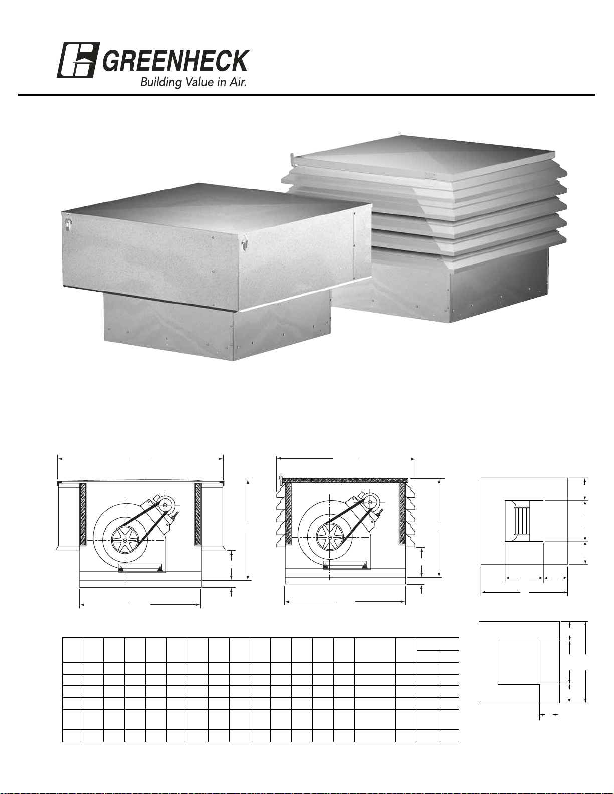
Model RSF
Model RSFP
READ AND SAVE THESE INSTRUCTIONS
Roof Supply Fans
Models RSF and RSFP
PN 453148
Installation, Operation and Maintenance Manual
Greenheck Model RSF and RSFP fans are thoroughly inspected and test run at the factory, however damage
may occur during handling and shipping. Consequently, it is important to inspect the unit for visible and
concealed damage before beginning installation. Report any damage to the shipper immediately. In addition,
assure all accessory items are accounted for.
Dimensional Data
1
RSF
RSFP
BASE OF UNIT
OPTIONAL DUCT ADAPTER
Fan
SizeASQ.BSQ.BLSQ.
CCLD F G H J
K
SQ.LSQ.
M
Louver
Tiers
RSFP
Nominal
Filter
Weights
RSF RSFP
90 26 351/8 317/8 231/4 253/8 101/4 121/4 103/4 75/8 67/8 241/2 121/4 61/8 (4) 12x20 3 145 126
100 30 41
1
/8 357/8 231/4 253/8 101/4 135/8 117/8 91/16 83/16 281/2 141/4 71/8 (4) 12x25 3 173 146
120 34 47
1
/8 397/8 271/4 293/8 101/4 161/8 137/8 101/16 815/16 321/2 181/4 71/8 (4) 16x25 4 225 180
150 40 53
1
/8 457/8 311/4 333/8 101/4 191/8 161/2 111/4 107/16 381/2 201/4 91/8 (8) 16x20 5 336 250
180 46 61
1
/8 517/8 341/4 353/8 121/4 221/2 191/2 101/8 113/4 441/2 261/4 91/8
(4) 16x20
5 400 285
(4) 20x20
200 52 731/8 583/16 391/4 403/8 121/4 231/4 251/4 133/8 143/8 501/2 301/4 101/8 (8) 20x25 6 620 431
All dimensions are in inches.
®
B SQ.
C
D
2 1/2 in.
SQ.
A
BL SQ.
SQ.
A
D
2 1/2 in.
CL
G
A
M
H
M
L
SQ.KSQ.
M
J
F
J
Page 2
2
Lifting
Lifting the RSF and RSFP model fans must be done with care to avoid
damaging the housing. For Model RSF attach four lifting devices under the
outer housing, each device beneath the vertical row of fasteners (Fig. 1).
Lifting devices should be a minimum of 3 in. wide to avoid damaging the
sheet metal housing. Do not lift Model RSF near the center of the outer
housing.
For Model RSFP attach a minimum of four lifting devices under an exterior
louver panel, each device near the corner of the louvered housing.
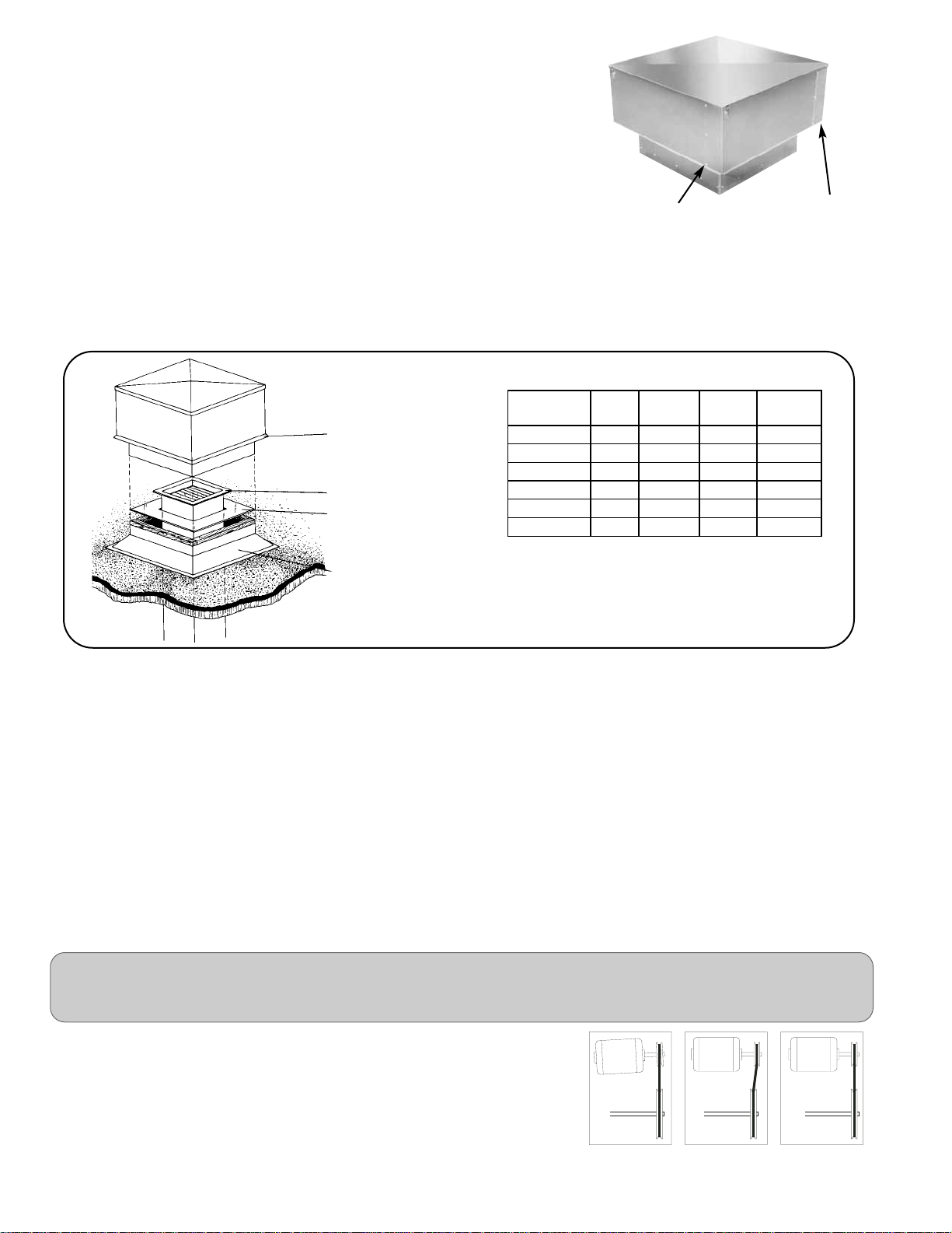
Installation
Move the fan to its intended location and fasten it securely through mounting holes provided in the fan base. Shims may be
necessary depending upon thickness of the roofing material. For ducted applications, an optional duct adapter (if provided)
is attached and holds the ductwork in place prior to installing the unit. The following diagram shows a typical installation
with prefab roof curb and ductwork.
Access to the motor compartment is made by releasing four latches which secure the cover. The cover should be placed in
an area where wind will not blow it off the roof.
Electrical Connection
The electrical supply must be compatible with the fan motor with regard to voltage, phase and amperage capacity.
Moreover, the electrical supply line must be properly fused and conform to local and national electrical codes.
Electrical lead-in wires should be routed through the pre-punched hole in the optional duct adapter (if provided) and the
punched hole in the bottom of the fan housing. Electrical wires must be located so as not to rub on moving components.
The electrical supply line is connected to the optional safety disconnect switch (if provided) or wired directly to the motor.
Pre-Starting Checks
Note: For units shipped with motor and drives separate, refer to the Motor Mounting Instructions included in the hardware
bag.
Check all fasteners and set screws for tightness. Rotate the fan wheel by hand
to assure it turns freely and is centered between the inlets. Check pulleys and
belts for proper alignment to avoid premature belt wear, noise, vibration and
power loss. Motor and fan pulleys must be parallel and in line (Fig. 2).
The adjustable motor pulley is set at the factory for the fan RPM specified. Fan
speed can be increased by closing or decreased by opening the adjustable
motor pulley. Two groove variable pitch pulleys must be adjusted an equal
Fig. 1
Lift Here
Lift Here
TYPICAL INSTALLATION
RSF unit with prepunched
mounting holes and 21/2 inch
skirt to aid in installation.
Ductwork (by others)
Duct adapter (optional) allows
ductwork to be completed
prior to setting unit on curb.
Roof Curb
Fan
Curb
Size*
Recom.
Roof
Opening
Duct
Size
ID
Nominal
Damper
Size
RSF/RSFP- 90 24
1
/2 15 12 12 x 12
RSF/RSFP- 100 28
1
/2 17 14 14 x 14
RSF/RSFP- 120 32
1
/2 21 18 18 x 18
RSF/RSFP- 150 38
1
/2 23 20 20 x 20
RSF/RSFP- 180 44
1
/2 29 26 26 x 26
RSF/RSFP- 200 50
1
/2 33 30 30 x 30
All dimensions are in inches.
Note: In cases where extreme snow depths may be
encountered, extended base may be required to raise unit
or condensation pans may be required in ductwork.
*Recommended curb size shown is outside curb
dimension without roofing and flashing.
WARNING!
DISCONNECT AND SECURE TO THE “OFF” POSITION ALL ELECTRICAL POWER TO THE FAN PRIOR TO INSPECTION OR
SERVICING. FAILURE TO COMPLY WITH THIS SAFETY PRECAUTION COULD RESULT IN SERIOUS INJURY OR DEATH.
Fig. 2
WRONG WRONG CORRECT
Page 3

3
number of turns open. Any increase in fan speed results in an increase in horsepower required for the motor. Motor load
amperes should always be checked and compared to nameplate rating when changing fan speed.
Direction of fan wheel rotation is critical. A fan wheel rotating in the wrong
direction will result in reduced airflow, motor overloading and possible burnout. Check wheel rotation by momentarily turning the fan on.
Rotation should be in the same direction as airflow at the outlet. See housing
and wheel examples in Fig. 3. IMPORTANT NOTE: RSF/RSFP fans should be
operated only when attached to the completed system. Without proper
static pressure loading, the motor may be overloaded and burnout may
occur.
Routine Maintenance - See WARNING Page 2
To preserve the reliability and performance designed into the fan, regularly scheduled maintenance should be performed.
Items to be checked at each maintenance interval are filters, belts, bearings, fasteners, lubrication and removal of dust and
dirt.
Filters
1 inch washable aluminum mesh filters are standard on Model RSF and RSFP fans. (Optional 2 inch filters may be supplied
on some fans). Filters should be cleaned on a regular basis for optimum efficiency.
To remove the filters, first remove the fan cover by releasing the four latches. (Place the cover in an area where wind will not
blow it off the roof). The filters can be lifted out and washed in a mild detergent solution. If desired, an adhesive spray
available at most filter distributors can be applied to increase filter efficiency.
Belts
Belt tension should be checked two times during the first 24 hours of
operation and during each scheduled maintenance thereafter. Premature belt
failures are frequently caused by improper belt tension, either too tight or
loose. The proper belt tension for operating a V-belt is the lowest tension at
which the belt will not slip at peak load conditions. For initial tensioning, belt
deflection should be 1/64 inch for each inch of belt span, determined by using
moderate thumb pressure half way between pulley centers. For example, the
belt deflection should be 1/2 inch if the belt span is 32 inches (Fig. 4).
Belt tension can be adjusted by loosening the motor plate hinge bolts and
adjusting the jack screws as required. RSF/RSFP units are supplied with
either a painted steel motor bracket or a galvanized motor plate for larger
motor frames. To adjust belt tension on units equipped with the painted steel
motor bracket, simply adjust the single jack screw.
For units equipped with a galvanized motor plate, both jack screws must be adjusted equally. Check pulley and belt
alignment after adjusting belt tension (Fig. 2).
Lubrication
Fan bearings on Model RSF and RSFP are permanently lubricated. Motor bearings equipped with grease fittings should be
lubricated in accordance with instructions on the motor nameplate. Motors without grease fittings are lubricated for life.
Cleaning
Motors and Fan Wheels require periodic cleaning to remove dust and dirt which may accumulate. Motor cleaning should be
limited to the exterior surface only. Removing dust and dirt from the motor housing assists in motor cooling and prolongs
motor life. Motors should never be sprayed with steam, water or solvents.
Fan wheels which are left to accumulate dust and dirt will have poor air performance, loss of efficiency and possible
damaging vibration due to an unbalanced condition.
Periodic cleaning is a good investment in preserving the reliability and performance designed into the fan.
Fig. 3
Fig. 4
AIRFLOW
T
O
A
R
T
I
O
N
R
O
T
A
T
I
O
N
Belt Span
Deflection =
Belt Span
64
Page 4

Warranty
Greenheck warrants this equipment to be free from defects in material and workmanship for a period of one year from
the purchase date. Any units or parts which prove to be defective during the warranty period will be replaced at our
option when returned to our factory, transportation prepaid.
The motor is warranted by the motor manufacturer for a period of one year. Should the motor furnished by Greenheck
prove defective during this period, it should be returned to the nearest authorized motor service station. Greenheck
will not be responsible for any removal or installation costs.
GREENHECK
RSF/RSFP IOM
#453148 Rev 2 Dec 2004
Copyright © 2004 Greenheck Fan Corp.
*Galvanized motor plate shown. Painted steel motor bracket used on units with smaller motor frame sizes.
Note: The unit serial number, located on the Greenheck name tag, should be provided when requesting parts or
information.
Filters
Shaft Pulley
Blower Mounting Angle
Shock Mounts (4)
Motor Pulley
Motor
*Motor Plate
Blower Unit
Belt
PARTS LIST
As a result of our commitment to continuous improvement, Greenheck reserves the right to change specifications without notice.
P.O. BOX 410 SCHOFIELD, WISCONSIN 54476-0410
®
PH. 715-359-6171
www.greenheck.com
 Loading...