

Page 1
Part Number 463687
Centrifugal (BISW, AFSW, BIDW, AFDW)
Industrial Process (IPA, IPO, IPW)
®
Plenum (QEM, QEP)
Plug (PLG)
Filtered Supply (LSF)
Installation, Operation and Maintenance Manual
Please read and save these instructions. Read carefully before attempting to assemble, install, operate or maintain the
product described. Protect yourself and others by observing all safety information. Failure to comply with instructions
could result in personal injury and/or property damage! Retain instructions for future reference.
Centrifugal and Industrial
Plug PlenumFiltered Supply
General Safety Information
Only qualified personnel should install this fan. Personnel
should have a clear understanding of these instructions
and should be aware of general safety precautions.
Improper installation can result in electric shock, possible
injury due to coming in contact with moving parts, as well
as other potential hazards. Other considerations may
be required if high winds or seismic activity are present.
If more information is needed, contact a licensed
professional engineer before moving forward.
DANGER
Always disconnect power before working on or near
a fan. Lock and tag the disconnect switch or breaker
to prevent accidental power up.
CAUTION
When servicing the fan, motor may be hot enough
to cause pain or injury. Allow motor to cool before
servicing.
CAUTION
Precaution should be taken in explosive
atmospheres.
1. Follow all local electrical and safety codes, as well
as the National Electrical Code (NEC), the National
Fire Protection Agency (NFPA), where applicable.
Follow the Canadian Electric Code (CEC) in
Canada.
2. The rotation of the wheel is critical. It must be free
to rotate without striking or rubbing any stationary
objects.
3. Motor must be securely and adequately grounded.
4. Do not spin fan wheel faster than max cataloged
fan rpm. Adjustments to fan speed significantly
effects motor load. If the fan RPM is changed, the
motor current should be checked to make sure it is
not exceeding the motor nameplate amps.
5. Do not allow the power cable to kink or come in
contact with oil, grease, hot surfaces or chemicals.
Replace cord immediately if damaged.
6. Verify that the power source is compatible with the
equipment.
7. Never open access doors to a duct while the fan is
running.
Centrifugal, Industrial, Plug, Plenum and Filtered Supply
1
Page 2

Receiving
Upon receiving the product check to make sure all
items are accounted for by referencing the bill of
lading to ensure all items were received. Inspect
each crate for shipping damage before accepting
delivery. Notify the carrier if any damage is noticed.
The carrier will make notification on the delivery
receipt acknowledging any damage to the product.
All damage should be noted on all the copies of the
bill of lading which is countersigned by the delivering
carrier. A Carrier Inspection Report should be filled out
by the carrier upon arrival and the Traffic Department.
If damaged upon arrival, file claim with carrier. Any
physical damage to the unit after acceptance is not
the responsibility of Greenheck Fan Corporation.
Unpacking
Verify that all required parts and the correct quantity
of each item have been received. If any items are
missing report shortages to your local representative
to arrange for obtaining missing parts. Sometimes it
is not possible that all items for the unit be shipped
together due to availability of transportation and truck
space. Confirmation of shipment(s) must be limited to
only items on the bill of lading.
Handling
Fans are to be rigged and moved by the lifting
brackets provided or by the skid when a forklift is
used. Location of brackets varies by model and size.
Handle in such a manner as to keep from scratching
or chipping the coating. Damaged finish may reduce
the ability of the fan to resist corrosion. Fans should
never be lifted by the shaft, fan housing, motor, belt
guard, windband or accessories.
Storage
• Rotatefanwheelmonthlyandpurgebearingsonce
every three months
• Energizefanmotoronceeverythreemonths
• Storebeltsflattokeepthemfromwarping&stretching
• Storeunitinlocationwhichdoesnothavevibration
• Afterstorageperiod,purgegreasebeforeputtingfan
into service
If storage of fan is in a humid, dusty or corrosive
atmosphere, rotate the fan and purge the bearings
once a month. Improper storage which results in
damage to the fan will void the warranty.
Fans are protected against damage during shipment. If
the unit cannot be installed and operated immediately,
precautions need to be taken to prevent deterioration
of the unit during storage. The user assumes
responsibility of the fan and accessories while in
storage. The manufacturer will not be responsible
for damage during storage. These suggestions are
provided solely as a convenience to the user.
Centrifugal, Industrial, Plug, Plenum and Filtered Supply
2
INDOOR
The ideal environment for the storage of fans and
accessories is indoors, above grade, in a low humidity
atmosphere which is sealed to prevent the entry of
blowing dust, rain, or snow. Temperatures should be
evenly maintained between 30°F (-1°C) and 110°F (43°C)
(wide temperature swings may cause condensation
and “sweating” of metal parts). All accessories must be
stored indoors in a clean, dry atmosphere.
Remove any accumulations of dirt, water, ice or snow
and wipe dry before moving to indoor storage. To avoid
“sweating” of metal parts allow cold parts to reach
room temperature. To dry parts and packages use a
portable electric heater to get rid of any moisture build
up. Leave coverings loose to permit air circulation and
to allow for periodic inspection.
The unit should be stored at least 3½ in. (89 mm) off the
floor on wooden blocks covered with moisture proof
paper or polyethylene sheathing. Aisles between parts
and along all walls should be provided to permit air
circulation and space for inspection.
OUTDOOR
Roads or aisles for portable cranes and hauling
equipment are needed.
The fan should be placed on a level surface to prevent
water from leaking into the fan. The fan should be
elevated on an adequate number of wooden blocks so
that it is above water and snow levels and has enough
blocking to prevent it from settling into soft ground.
Locate parts far enough apart to permit air circulation,
sunlight, and space for periodic inspection. To minimize
water accumulation, place all fan parts on blocking
supports so that rain water will run off.
Do not cover parts with plastic film or tarps as these
cause condensation of moisture from the air passing
through heating and cooling cycles.
Fan wheels should be blocked to prevent spinning
caused by strong winds.
Inspection & Maintenance during Storage
While in storage, inspect fans once per month. Keep a
record of inspection and maintenance performed.
If moisture or dirt accumulations are found on parts,
the source should be located and eliminated. At each
inspection, rotate the wheel by hand ten to fifteen
revolutions to distribute lubricant on motor. If paint
deterioration begins, consideration should be given to
touch-up or repainting. Fans with special coatings may
require special techniques for touch-up or repair.
Machined parts coated with rust preventive should be
restored to good condition promptly if signs of rust occur.
Immediately remove the original rust preventive coating
with petroleum solvent and clean with lint-free cloths.
Polish any remaining rust from surface with crocus cloth
or fine emery paper and oil. Do not destroy the continuity
of the surfaces. Wipe clean thoroughly with Tectyl® 506
(Ashland Inc.) or the equivalent. For hard to reach internal
surfaces or for occasional use, consider using Tectyl®
511M Rust Preventive or WD-40® or the equivalent.
Page 3

Table of Contents
General Information
Receiving.................................2
Handling . . . . . . . . . . . . . . . . . . . . . . . . . . . . . . . . . 2
Storage . . . . . . . . . . . . . . . . . . . . . . . . . . . . . . . . . . 2
Installation Recommendations
Centrifugal (SWSI, DWDI) .................. 4-5
Plenum / Plug . . . . . . . . . . . . . . . . . . . . . . . . . . . . . 5
Belt Guards ...............................6
Bases....................................7
Rotatable Housing . . . . . . . . . . . . . . . . . . . . . . . . . 7
RadialGap,Overlap&WheelAlignment . . . . . . 8-9
Flexible Couplings ...........................9
Variable Frequency Drives (VFDs) ...............9
V-Belt Drives ................................9
Unit Start-Up...............................10
Vibration ..................................10
Routine Maintenance . . . . . . . . . . . . . . . . . . . . . 11-12
Motors ..................................11
Shaft Bearings............................ 11
V-Belt Drive ..............................12
Unit Identification . . . . . . . . . . . . . . . . . . . . . . . . . . . 12
Parts List .................................. 13
Troubleshooting . . . . . . . . . . . . . . . . . . . . . . . . . . . . 14
Maintenance Log . . . . . . . . . . . . . . . . . . . . . . . . . . . 15
Warranty ........................... Backcover
CAUTION
When installing a fan, ensure the proper protective
devices are used to protect personnel from
moving parts and other hazards. A complete
line of protective accessories are available from
Greenheck including: inlet guards, outlet guards,
belt guards, shaft guards, protective cages and
electrical disconnects.
Electrical Disconnects
All fan motors should have disconnects located in
close visual proximity to turn off electrical service.
Service disconnects shall be locked out when
maintenance is being performed.
Moving Parts
All moving parts must have guards to protect
personnel. Refer to local codes for requirements
as to the number, type and design. Fully secure fan
wheel before performing any maintenance. The fan
wheel may start “free wheeling” even if all electrical
power has been disconnected. Before the initial
start-up or any restart, check the guards (belt,
shaft, inlet and outlet) and check the access doors
to ensure that they are installed and secure.
Centrifugal, Industrial, Plug, Plenum and Filtered Supply
3
Page 4
R
o
t
a
t
i
o
n
R
o
t
a
t
i
o
n
R
o
t
a
t
i
o
n
R
o
t
a
t
i
o
n
Turning
Vanes
POOR
POOR
GOOD
Length of Straight Duct
GOOD
One fan
wheel
diameter
One fan
diameter
3/4 to
one fan
wheel
diameter
R
o
t
a
t
i
o
n
R
o
t
a
t
i
o
n
Turning
Vanes
POOR
GOOD
R
o
t
a
t
i
o
n
R
o
t
a
t
i
o
n
R
o
t
a
t
i
o
n
R
o
t
a
t
i
o
n
Turning
Vanes
POOR
POOR
GOOD
Length of Straight Duct
GOOD
3/4 to
one fan
wheel
diameter
SYSTEM EFFECT FACTORS CURVES
STATIC PRESSURE LOSS
1.2
1.0
0.8
0.6
0.4
0.2
0.0
CURVE 1
CURVE 2
CURVE 3
CURVE 4
R
o
t
a
t
i
o
n
R
o
t
a
t
i
o
n
R
o
t
a
t
i
o
n
Turning
Vanes
POOR
POOR
GOOD
POOR
Length of Straight Duct
GOOD
One fan
wheel
diameter
3/4 to
one fan
wheel
diameter
One fan
diameter
3/4 to
one fan
wheel
diameter
SYSTEM EFFECT FACTORS CURVES
STATIC PRESSURE LOSS
1.2
1.0
0.8
0.6
0.4
0.2
0.0
CURVE 1
CURVE 2
CURVE 3
CURVE 4
Installation
R
o
t
a
t
i
o
n
R
o
t
a
t
i
o
n
R
o
t
a
t
i
o
n
R
o
t
a
t
i
o
n
Turning
Vanes
POOR
POOR
GOOD
Length of Straight Duct
GOOD
R
o
t
a
t
i
o
n
R
o
t
a
t
i
o
n
R
o
t
a
t
i
o
n
Turning
Vanes
POOR
POOR
GOOD
One fan
diameter
3/4 to one
fan
wheel
diameter
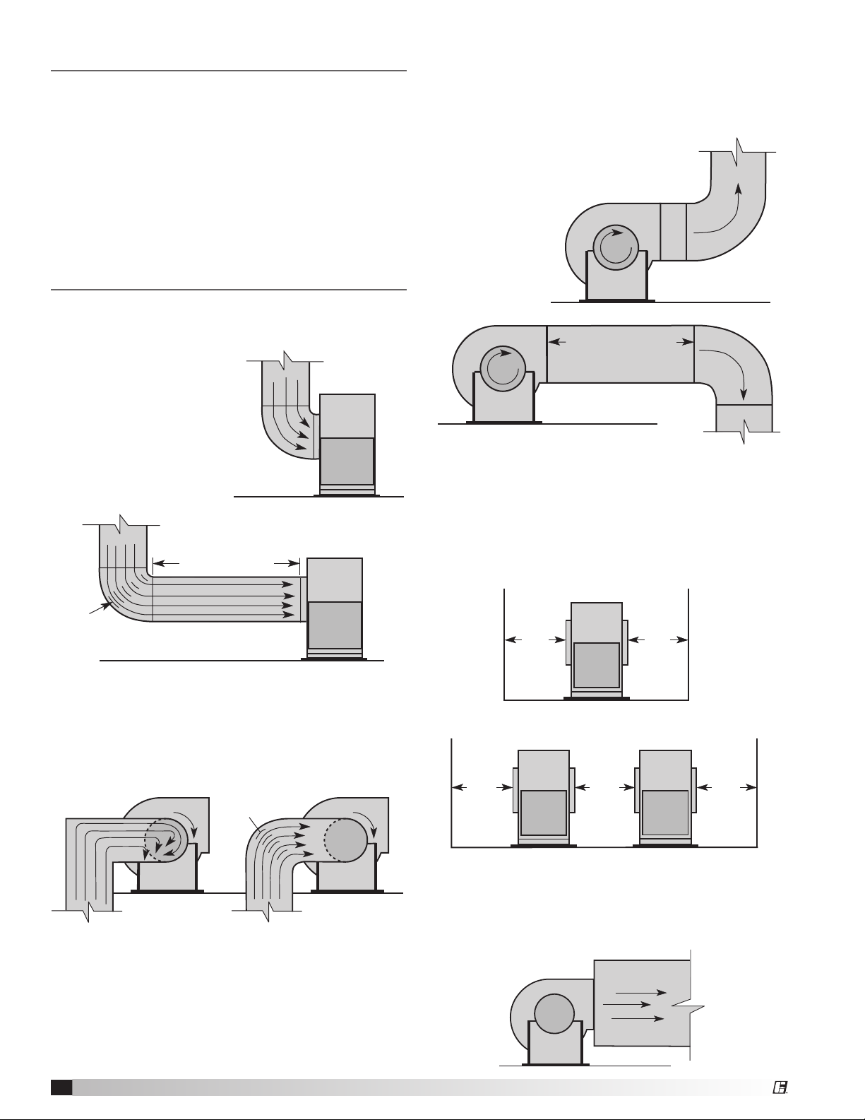
Installations with inlet or discharge configurations
that deviate from this standard may result in reduced
fan performance. Restricted or unstable flow at the
fan inlet can cause pre-rotation of incoming air or
uneven loading of the fan wheel yielding large system
losses and increased sound levels. Free discharge
or turbulent flow in the discharge ductwork will also
result in system effect losses. Refer to the following
diagrams for the most efficient installation conditions.
Centrifugal and Industrial Process
Fans Installations
Ducted Inlet Installations
Inlet Duct Turns - Installation of a duct turn or elbow
too close to the fan inlet
reduces fan performance
because air is loaded
unevenly into the fan
wheel. To achieve full fan
performance, there should
be at least three fan wheel
diameters between the turn
POOR
or elbow and the fan inlet.
Three fan wheel diameters
Turning
Vanes
GOOD
Ducted Outlet Installations
Discharge Duct Turns - Duct turns located near the
fan discharge should always be in the direction of the
fan rotation.
Fan performance is reduced when duct
turns are made immediately off the
fan discharge. To achieve cataloged
fan performance there
should be at least
three equivalent
duct diameters of
straight ductwork
between the fan
discharge and
any duct turns.
Non-Ducted Installations
Inlet Clearance - Installation of a fan with an open
inlet too close to a wall or bulkhead will cause
reduced fan performance. It is desirable to have
one fan wheel diameter between parallel fan units
and a minimum of three-fourths of a wheel diameter
between the fan inlet and the wall.
3/4 to one
fan
wheel
diameter
3/4 to one
fan
wheel
diameter
Inlet Spin -
Inlet spin is a frequent cause of reduced
fan performance. The change in fan performance is a
function of the intensity of spin and not easily defined.
The best solution is proper duct design and airflow
patterns. Turning vanes reduce the effects of inlet spin.
t
a
t
i
o
n
Turning
Vanes
R
o
t
a
t
i
o
GOOD
R
o
POOR
Centrifugal, Industrial, Plug, Plenum and Filtered Supply
4
n
3/4 to
one fan
wheel
diameter
Single Fan Installation
3/4 to
one fan
wheel
diameter
One fan
diameter
Parallel Fan Installation
Free Discharge - Free or abrupt discharge into a
plenum results in a reduction in fan performance. The
effect of discharge static regain is not realized.
Page 5
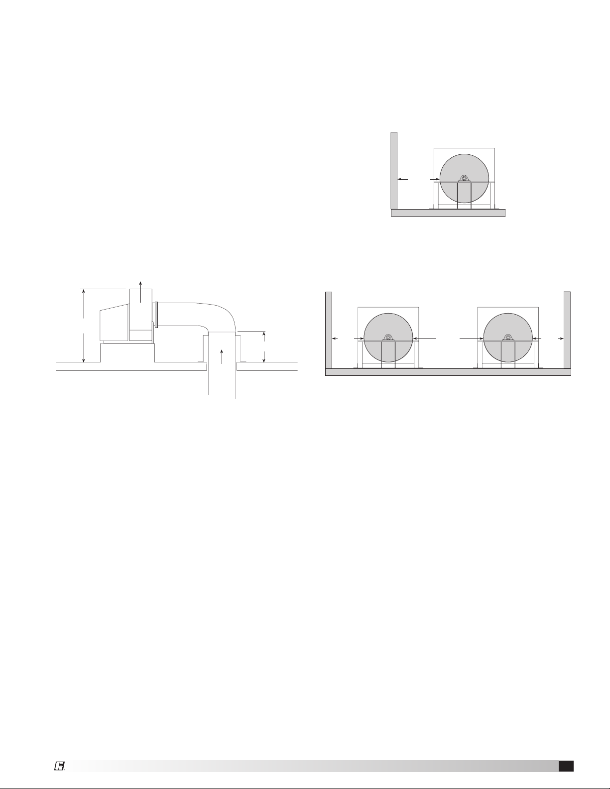
Outdoor Installation for UL/cUL 762 Listed Fans
for Restaurant Exhaust
The UL/cUL 762 listing for restaurant exhaust is
available on the BISW models. Fans are listed for a
maximum operating temperature of 400°F (204°C) and
include a bolted access door and 1 inch (25 mm) drain
connection. An outlet guard is strongly recommended
when the fan discharge is accessible. An upblast
discharge is recommended. The fan discharge must
be a minimum of 40 inches (1016 mm) above the
roof line and the exhaust duct must be fully welded
to a distance of 18 inches (457 mm) above the roof
surface.
The drawing below is for dimensional information
only. See the latest edition of NFPA 96 Standard for
Ventilation Control and Fire Protection of Commercial
Cooking Operations for detailed installation
instructions, materials, duct connections and
clearances.
Upblast Discharge
40 in.**
Weatherhood
1016 mm
18 in.*
457 mm
Plenum and Plug Fans - Installation
Unhoused Wheels
Adjacent Walls - The distance between the fan and
walls or ceilings will effect the performance of the fan.
The recommended distance between the fan wheel
and any wall is a minimum of one-half wheel diameter.
Multiple walls reduce the performance even more.
One-half
wheel
diameter
Side by Side - When two or more plenum fans are
in parallel, there should be at least one fan diameter
spacing between the wheels. Applications with less
spacing will experience performance losses.
One-half
wheel
diameter
One
wheel
diameter
One-half
wheel
diameter
** Per NFPA 96 the fan discharge
must be a minimum of 40 inches
(1016 mm) above the roof surface.
Duct
from
Kitchen
Hood
* Per NFPA 96 the duct must be
all welded construction to a
minimum distance of 18 in.
(457 mm) above the roof surface
Centrifugal, Industrial, Plug, Plenum and Filtered Supply
5
Page 6

Fan
Z
Y
W
X
Belt Guards
Greenheck offers
various types of
customized belt
guards dependent
upon fan model,
arrangement and
motor position.
Motor position is
determined from
the drive side.
The various types of belt guards are shown in
illustrations. If the guard is not purchased from
Greenheck, they must be supplied by the installer or
owner.
If the belt guard is not factory mounted or was not
supplied by Greenheck, then it must be field mounted.
Brackets and mounting hardware are the responsibility
of the installer. The figures below illustrate suggested
attachment points for belt guard mounting bracket
locations. These locations vary with motor mounting
position, arrangement, and fan type. The bearing
supports and fan structure are used in most instances
and when the motor is not mounted to the fan itself, a
bracket should also be located near it. This information
is intended as only a guide and actual field conditions
may dictate another mounting location for the guard
brackets. Refer to local codes for securing guarding.
QEP&Single-Width-Arr.1,3(MotorPositionW/Z)
Single-Width - Arr. 9, 10
PLG&QEM
QEP&Single-Width-Arr.1,3(MotorPositionX/Y)
Motor Position: W / Z
Arrangement - 1, 3
Motor Position: L / R
Arrangement 9
Suggested Attachment Points
(shaded gray)
Motor Position: X / Y
Arrangement - 1, 3
Motor Position: Side
Double-Width - Arr. 3 (Motor Position W/Z)
Double-Width - Arr. 3 (Motor Position X/Y)
Centrifugal, Industrial, Plug, Plenum and Filtered Supply
6
Page 7

Bases (Foundation and Isolation)
Critical to every fan installation is a strong, level
foundation. A reinforced poured concrete pad with a
structural steel base or inertia base provides an excellent
foundation. Structural bases must be sturdy enough, with
welded construction, to prevent flexing and vibration.
To eliminate vibration and noise from being transferred
to the building, vibration isolators should be used. The
fan is mounted directly on the isolation base and must
be supported for the entire length of the fan base angle
(Refer to the installation manual for structural bases if the
base was supplied by Greenheck). Isolators are installed
between the isolation base and the foundation.
After the fan, isolation base, and isolators are installed,
the entire assembly must be leveled. Position the level on
the isolation base, not the fan shaft, for proper leveling.
Additionally, the motor and fan shafts must be level and
parallel relative to each other for proper alignment.
Rotatable Housings
It may be necessary to rotate the scroll of the fan to
achieve a different discharge position than what was
originally supplied. Centrifugal fans models BISW,
AFSW (sizes 7 - 30, arr. 1, 4, 8, 9, and 10, class I and
II) and Industrial Process fans (sizes 5–19, standard
and heavy duty) have the flexibility to be rotated
in the field. This is accomplished by removing the
housing bolts, rotating the housing to a new discharge
position, and reinstalling the bolts.
Typical Fan on Isolation Base
Centrifugal, Industrial, Plug, Plenum and Filtered Supply
7
Page 8

Radial Gap, Overlap and Wheel Alignment
Efficient fan performance can be maintained by having the correct radial gap, overlap and wheel alignment.
These items should be checked after the fan has been in operation for 24 hours and before start-up after the
unit has been serviced. Radial gap and overlap information applies to models: BISW, AFSW, BIDW, AFDW, LSF,
PLG, QEP and QEM.
BISW, AFSW, BIDW, AFDW,
LSF and PLG
Unit
Size
7 1
8 2
9 33⁄16
10 3
12 4
13 4
15 5
16 5
18 6
20 7
22 7
24 8
27 9
30 10
33 11
36 12
40 14
44 15
49 17
54 18
60 20
66 22
73 25
*A dimension does not apply to partial width wheels.
Radial Gap
Inlet Cone to Backplate
A Dimension*
± Tolerance
(in.)
3
3
7
7
7
13
7
±
⁄16
⁄16
⁄16
⁄16
⁄16
3
⁄8
⁄16
5
⁄8
⁄16
9
⁄16
7
⁄16
3
⁄4
3
⁄16
9
⁄16
1
⁄8
13
⁄16
15
⁄16
7
⁄8
1
⁄2
1/8 30
±
1/8 36
±
1/8 81
±
1/8 87
±
1/8 102
±
1/8 113
±
1/8 127
±
1/8 138
±
1/8 162
±
3/16 178
±
3/16 198
±
1/4 219
±
1/4 240
±
3/8 268
±
3/8 291
±
3/8 324
±
3/8 360
±
3/8 395
±
1/2 435
±
1/2 478
±
1/2 532
±
1/2 581
±
1/2 648
A Dimension*
± Tolerance
(mm)
±
3
±
3
±
3
±
3
±
3 1/8
±
3
±
3 1/8
±
3 3/16
±
3 3/16
±
5 1/4
±
5 1/4
±
6 5/16
±
6 3/8
±
10 3/8
±
10 7/16
±
10 7/16
±
10 1/2
±
10 9/16
±
13 5/8
±
13 5/8
±
13 3/4
±
13 7/8
±
13 1
is adjusted by loosening the inlet cone/ring bolts and centering the cone/ring on the wheel. If additional
Wheel Cone to Inlet Cone
Offset
± Tolerance
(in.)
QEP
±
1/16 3
±
1/16 3
±
1/16 5
±
1/16 5
±
1/16 6
±
1/16 6
±
1/16 8
±
1/16 9.5
±
1/16 9.5
±
1/16 11
±
1/8 11
±
1/8 13
±
1/8 14
±
1/8 16
±
1/8 16
±
1/8 19
±
1/8 22
±
1/8 25
Offset
± Tolerance
(mm)
±
1.5 7/16
±
1.5 7/16
±
1.5 7/16
±
1.5 7/16
±
1.5 7/16
±
1.5 7/16
±
1.5 7/16
±
1.5 9/16
±
1.5 9/16
±
1.5 9/16
±
±
±
±
±
±
±
±
Wheel Cone to Inlet Cone
± Tolerance
3 9/16
3
3
3
3
3
3
3
Offset
(in.)
±
±
±
±
±
±
±
QEM
1/16 11
1/16 11
1/16 11
1/16 11
1/16 11
1/16 11
1/16 11
±
1/8 14
±
1/8 14
±
1/8 14
±
1/8 14
Offset
± Tolerance
(mm)
±
1.5
±
1.5
±
1.5
±
1.5
±
1.5
±
1.5
±
1.5
±
1.5
±
1.5
±
1.5
±
3
adjustment is required to maintain a constant radial gap, loosening the bearing bolts and centering the wheel is
acceptable as a secondary option.
Overlap, or offset, is adjusted by loosening the wheel hub from the shaft and moving the wheel to the desired
position along the shaft. The transition between the inlet cone and wheel should be as shown; there is a smooth
feel to the profile when moving from one component to the other. Overlap on double width fans is set by having
equal spacing on each side of the wheel.
Overlap
Overlap Overlap
A
Inlet
Cone
Wheel
Radial
Radial
Gap
BISW, AFSW, PLG
Centrifugal, Industrial, Plug, Plenum and Filtered Supply
8
Gap
BIDW, AFDW, LSF
Wheel
Offset
Inlet
Cone
QEM, QEP
Page 9

Correct wheel alignment
MOTOR MOTOR
Equal Spacing
for an industrial process
fan (model IPA, IPO or
IPW) is achieved by
centering the wheel in
the housing.
Housing
Wheel
Flexible Couplings (Arr. 8 Only)
Check for misalignment between the coupling halves.
Parallel and angular misalignment and separation gap
are illustrated below. Refer to coupling manufacturer’s
installation instructions for allowable misalignment
and separation gap tolerances. When correcting for
misalignment using shims, the shims should only be
located under the motor. Do not place shims under the
shaft bearings.
After aligning procedure, check for tightness of all
coupling component pieces and ensure that they are
clean from dirt and debris.
Parallel Misalignment
Angular Misalignment
Separation Gap
V-Belt Drives
The V-belt drive components, when supplied by
Greenheck Fan Corporation, have been carefully
selected for this unit’s specific operating condition.
CAUTION
Changing V-belt drive components could result in
unsafe operating conditions which may cause
personal injury or failure of the following
components:
1. Fan shaft
2. Fan wheel
3. Bearings
V-Belt Drive Installation
1. Remove the protective coating from the end of the
fan shaft and assure that it is free of nicks and burrs.
2. Check fan and motor shafts for parallel and angular
alignment.
3. Slide sheaves on shafts - do not drive sheaves on as
this may result in bearing damage.
4. Align fan and motor sheaves with
a straight-edge or string, and
tighten.
5. Place belts over sheaves.
Do not pry or force belts,
as this could result in
damage to the cords in
the belts.
6. Adjust the tension until
the belts appear snug.
Run the unit for a few minutes (see section on
unit start-up) and allow the belts to seat properly.
Refer to Greenheck’s Product Application Guide
“Measuring Belt Tension” for additional information.
7. With the fan off, adjust the belt tension by moving
the motor base. (See belt tensioning procedures in
the maintenance section of this manual). When in
operation, the tight side of the belts should be in a
straight line from sheave to sheave with a slight bow
on the slack side.
3. Bearings
4. V-belt
5. Motor
Variable Frequency Drive Operation
WARNING
For operation with Variable Frequency Drive (VFD),
always check motor amps when adjusting the
operating frequency. Motor may be sized for the
original selected operating speed under 60 Hz.
Bypassing the VFD or increasing the speed from this
original selection, even if less than 60 Hz, may cause
motor overload or failure. Consult factory–with fan
serial number–before increasing the upper limiting
frequency.
Always check the fan rpm when adjusting the
operating frequency. Do not exceed maximum class
fan rpm of the wheel.
Improper sheave
alignment
Centrifugal, Industrial, Plug, Plenum and Filtered Supply
Proper sheave
alignment
9
Page 10

Unit Start-Up
1. Disconnect and lock-out all power switches to fan.
See warning below.
2. Check all fasteners, set screws and locking collars on
the fan, bearings, drive, motor base and accessories
for tightness.
3. Rotate the fan wheel by hand and assure no parts
are rubbing.
4. Check for bearing alignment and lubrication.
5. Check for coupling alignment (Arr. 8 only).
6.
Check the V-belt drive for proper alignment and tension.
7. Check all guarding (if supplied) for being securely
attached and not interfering with rotating parts.
8. Check operation of variable inlet vanes or discharge
dampers (if supplied) for freedom of movement.
9. Check all electrical connections for proper
attachment.
10. Check housing and ductwork, if accessible, for
obstructions and foreign material that may damage
the fan wheel.
WARNING
Disconnect and secure to the “Off” position all
electrical power to the fan prior to inspection
or servicing. Failure to comply with this safety
precaution could result in serious injury or death.
Additional Steps for Initial Start-Up
1. Check for proper wheel rotation by momentarily
energizing the fan. Rotation is always determined
by viewing the wheel from the drive side and should
correspond to the rotation decal affixed to the unit.
One of the most frequently encountered problems
with centrifugal fans is motors which are wired to
run in the wrong direction. This is especially true
with 3-phase installations where the motor will
run in either direction, depending on how it has
been wired. To reverse rotation of a 3-phase motor,
interchange any two of the three electrical leads.
Single phase motors can be reversed by changing
internal connections as described on the motor
label or wiring diagram.
Clockwise Rotation
Centrifugal
Backward Inclined
Always viewed from the drive side.
Centrifugal
Airfoil
Industrial Process
Radial Blade
2. If the fan has inlet vanes, they should be partially
closed to reduce power requirements. This is
especially important if the fan is designed for a high
temperature application and is being started at
room temperature.
3. Fans with multi-speed motors should be checked
on low speed during initial start-up.
4. Check for unusual noise, vibration or overheating of
bearings. Refer to the “Troubleshooting” section of
this manual if a problem develops.
5. Grease may be forced out of the bearing seals
during initial start-up. This is a normal self-purging
feature of this type of bearing.
Vibration
Excessive vibration is the most frequent problem
experienced during initial start-up.
Common Sources of Vibration
1. Wheel Unbalance
2. Drive Pulley Misalignment
3. Incorrect Belt Tension
4. Bearing / Coupling Misalignment
5. Mechanical Looseness
6. Faulty Belts
7. Drive Component Unbalance
8. Poor Inlet/Outlet Conditions
9. Foundation Stiffness
Left unchecked, excessive vibration can cause a
multitude of problems, including structural and/or
component failure.
Many of these conditions can be discovered by careful
observation. Refer to the troubleshooting section
of this manual for corrective actions. If observation
cannot locate the source of vibration, a qualified
technician using vibration analysis equipment should
be consulted. If the problem is wheel unbalance, inplace balancing can be done providing there is access
to the fan wheel. Any correction weights added to
the wheel should be welded to either the wheel back
(single-plane balance) or to the wheel back and wheel
cone (two-plane balance).
Greenheck performs a vibration test on all centrifugal
fans before shipping. Three vibration readings are
taken on each bearing in the horizontal, vertical, and
axial directions. The allowable maximum vibration for
belt drive units is 0.15 in/sec. peak (0.08 in/sec. direct
drive) velocity filter-in for rigid mount and 0.20 in/sec.
peak velocity filter-in for flexible mount at the fan RPM
per AMCA Standard 204. These vibration signatures
are a permanent record of how the fan left the factory
and are available upon request.
Generally, fan vibration and noise is transmitted
to other parts of the building by the ductwork. To
eliminate this undesirable effect, the use of heavy
canvas connectors is recommended. If fireproof
material is required, FlexweaveTM 1000 - Type FN-30
can be used.
Centrifugal, Industrial, Plug, Plenum and Filtered Supply
10
Page 11

Routine Maintenance
Once the unit has been put into operation, a routine
maintenance schedule should be set up to accomplish
the following:
1. Lubrication of bearings and motor (see below).
2. Variable inlet vanes should be checked for freedom
of operation and wear.
3. Wheel, housing, bolts and set screws on the entire
fan should be checked for tightness.
4. Any dirt accumulation on the wheel or in the
housing should be removed to prevent unbalance
and possible damage.
5. Isolation bases should be checked for freedom
of movement and the bolts for tightness. Springs
should be checked for breaks and fatigue. Rubber
isolators should be checked for deterioration.
6. Inspect fan impeller and housing looking for fatigue,
corrosion, or wear.
When performing any service to the fan, disconnect
the electrical supply and secure fan impeller.
Motors
Motor maintenance is generally limited to cleaning
and lubrication. Cleaning should be limited to exterior
surfaces only. Removing dust and grease build up on
the motor housing assists proper motor cooling. Never
wash-down motor with high pressure spray. Greasing
of motors is only intended when fittings are provided.
Many fractional motors are permanently lubricated for
life and require no further lubrication. Motors supplied
with grease fittings should be greased in accordance
with the manufacturer’s recommendations. When
motor ambient temperature does not exceed 104°F
(40°C), the grease should be replaced after 2000 hours
of running time.
CAUTION
When operating conditions of the fan are to be
changed (speed, pressure, temperature, etc.),
consult Greenheck to determine if the unit can
operate safely at the new conditions.
Shaft Bearings
The bearings for Greenheck fans are carefully
selected to match the maximum load and operating
conditions of the specific class, arrangement, and
fan size. The instructions provided in this manual
and those provided by the bearing manufacturer, will
minimize any bearing problems. Bearings are the
most critical moving part of the fan, therefore special
care is required when mounting them on the unit and
maintaining them.
Refer to the following chart and the manufacturers
instructions for grease types and intervals for various
operating conditions. Never mix greases made with
different bases. This will cause a breakdown of the
grease and possible failure of the bearing.
Recommended Bearing Lubrication Schedule
Relubrication Schedule in Months*
Bearing Bore (inches)
Fan RPM
To 250 12 12 12 12 12 12 10 8
500 12 12 11 10 8 7 5 4
750 12 9 8 7 6 4 3 2
1000 12 7 6 5 4 3 2 1
1250 12 6 5 4 3 2 1 .5
1500 12 5 4 3 2 1 .75
2000 12 3 3 2 1 .5 .25
2500 12 2 2 1 .5 .25
3000 12 2 1 .5 .25
3500 12 1 .5 .25
4000 12 .5 .25
5000 12 .25
Number of
shots**
*Lubrication interval is based on 12 hour day operation and
maximum 160˚F housing temperature.
For 24 hour per day operation, the interval should be cut
in half.
**Lubricant should be added with the shaft rotating and
until clean grease is seen purging from the bearing.
The lubrication interval may be modified based on the
condition of the purged grease. If bearing is not visible to
observe purged grease, lubricate with number of shots
indicated for bore size.
• Forconditionsincludinghightemperatures,moisture,
• Lubricantshouldbeahighqualitylithiumcomplex
• Theuseofsyntheticlubricantswillincreaselubrication
• Storageperiodsofthreemonthsorlongerrequire
1
⁄2 - 111⁄8 -
4 8 8 10 16 25 41 57
dirt or excessive vibration, consult the factory for a
specific lubrication interval for your application.
grease conforming to NLGI Grade 2. Factory
recommends Mobilux EP-2 or synthetic Mobilith
SHC100.
intervals by approximately three times.
monthly rotation of the shaft and purging grease prior to
storage and start-up.
11⁄2
15⁄8 -
17⁄8
115⁄16 -
23⁄16
27⁄16
- 3
33⁄16 -
31⁄2
315⁄16 -
41⁄2
415⁄16 -
51⁄2
Centrifugal, Industrial, Plug, Plenum and Filtered Supply
11
Page 12

V-Belt Drives
V-belt drives must be checked on a regular basis
for wear, tension, alignment and dirt accumulation.
Premature or frequent belt failures can be caused by
improper belt tension, (either too loose or too tight)
or misaligned sheaves. Abnormally high belt tension
or drive misalignment will cause excessive bearing
loads and may result in failure of the fan and/or motor
bearings. Conversely, loose belts will cause squealing
on start-up, excessive belt flutter, slippage, and
overheated sheaves. Either excessively loose or tight
belts may cause fan vibration.
When replacing V-belts on multiple groove drives all
belts should be changed to provide uniform drive
loading. Do not pry belts on or off the sheave. Loosen
belt tension until belts can be removed by simply
lifting the belts off the sheaves. After replacing belts,
insure that slack in each belt is on the same side of
the drive. Belt dressing should never be used.
Do not install new belts on worn sheaves. If the
sheaves have grooves worn in them, they must be
replaced before new belts are installed.
Deflection =
Belt Span
64
Unit Identification
This tag is an example of an identification label on the
fan. The information provides general details about the
fan, as well as containing specific information unique to
the unit. When contacting your Greenheck representative
with future needs or questions, please have the
information on this label available.
MODEL
S/N
MARK
MAX FRPM @ 70˚ F
Model = General description of fan
S/N = Serial Number assigned by Greenheck,
which is a unique identifier for every unit
Mark = Customer supplied identification
Tags are mounted in an area which is clearly visible,
usually near the fan outlet on the drive side of the fan.
The exact tag location may differ due to fan model and
size.
Typical mounting locations for identifying tags.
Belt Span
The proper tension for operating a V-belt drive is
the lowest tension at which the belts will not slip at
peak load conditions. For more information about
measuring belt tension, refer to Greenheck’s Product
Application Guide, FA/127-10 Measuring Belt Tension.
Check belt tension before start up and after the first
24 hours of operation. The belt tension should also be
checked periodically thereafter.
Centrifugal, Industrial, Plug, Plenum and Filtered Supply
12
Page 13

Parts List
Belt Guard
Volume
Control
Damper
Outlet Flange
Outlet Guard
Isolation Base
Vibration Isolators (4)
Backdraft
Damper
Centrifugal
Shaft Guard
Heat Slinger
Backward Inclined Wheel
Inlet Cone External Inlet Vane Damper
Nested Inlet Vane Damper
Inlet Flange
Inlet Box
Damper
Inlet Guard
Inlet Companion Flange
Inlet Box
QEM
Protective Cage
Inlet Guard
Airfoil Wheel
Belt Guard
Protective Cage
Filters Filter Channels
Vibration
Isolation Base
Motor
Bearings
Shaft
Motor Slide Base
Drives/Sheaves
Inlet Guard
Protective Cage
QEPLSF
Airfoil Wheel
Shaft
Guard
Structural Isolation Base
Protective Cage
Belt Guard
Centrifugal, Industrial, Plug, Plenum and Filtered Supply
13
Page 14

Troubleshooting
Problem Cause Corrective Action
Adjust wheel and/or inlet cone.
Tighten wheel hub or bearing collars on shaft.
Tighten Sheaves on motor/fan shaft. Adjust belt tension. Align
sheaves properly (see V-Belt Drives section). Replace worn belts
or sheaves.
Replace defective bearing(s). Lubricate bearings.
Tighten collars and fasteners.
Clean all dirt off wheel. Check wheel balance, rebalance in place
if necessary.
Change obstructions in system. Use correction factor to adjust
for temperature/altitude. Resize ductwork. Clean filters/coils.
Change fan speed.*
Filters need to be cleaned or replaced. To remove the existing
filters, open the top hood panel(s). The filters can now be removed
by lifting them vertically and out of their racking. Be sure to
carefully note the quantity and size of the filters being removed as
some LSF units utilize multiple filters sizes. After the filters have
been cleaned, or new filters are ready to be installed, place the
filters back into the racks in the reverse order of which they were
removed. When all filters are in place, close and secure the top
roof panels.
Resize ductwork. Check proper operation of face and bypass
dampers. Check filters and access doors.
Check fuses/circuit breakers. Check for switches turned off or
disconnected. Check for correct supply voltage.
Assure motor is correct horsepower and not tripping overload
protector.
Replace damaged bearing. Relieve excessive belt tension. Align
bearings. Check for bent shaft.
Adjust tightness of belts. Replacement belts should be a matched
set.
Check alignment of shaft, motor and pulleys. Adjustable
pitch pulleys with motors over 15 hp are especially prone to
unbalance. Check wheel balance, rebalance if necessary.
Check alignment between coupling, motor and fan shafts.
Any adjustments should be made per coupling manufacturer’s
instructions. Shim only under motor.
Excessive Noise
Low CFM
High CFM
Static Pressure
Wrong
High Horsepower
Fan Doesn’t Operate
Overheated Shaft
Bearing
Excessive
Vibration
Wheel rubbing (inlet)
V-belt drive
Bearings
Wheel unbalance
Fan Check wheel for correct rotation. Increase fan speed.*
Duct system See page 3.
Fan Decrease fan speed.
Duct system Resize ductwork. Access door, filters, grilles not installed.
Duct system
has more or less
restriction than
anticipated
Dirty filters
•ModelLSF
Fan Check rotation of wheel. Reduce fan speed.
Duct system
Electrical supply
Drive Check for broken belts. Tighten loose pulleys.
Motor
Lubrication Check for excessive or insufficient grease in the bearings.
Mechanical
Belts
System unbalance
Coupling
misalignment
* Always check motor amps and compare to nameplate rating. Excessive fan speed may overload the motor and result in
motor failure. Do not exceed the maximum cataloged RPM of the fan.
NOTE: Always provide the unit model and serial numbers when requesting parts or service information.
Centrifugal, Industrial, Plug, Plenum and Filtered Supply
14
Page 15

Maintenance Log
Date __________________ Time _____________ AM/PM
Notes: __________________________________________
_________________________________________________
_________________________________________________
_________________________________________________
_________________________________________________
Date __________________ Time _____________ AM/PM
Notes: __________________________________________
_________________________________________________
_________________________________________________
_________________________________________________
_________________________________________________
Date __________________ Time _____________ AM/PM
Notes: __________________________________________
_________________________________________________
_________________________________________________
_________________________________________________
_________________________________________________
Date __________________ Time _____________ AM/PM
Notes: __________________________________________
_________________________________________________
_________________________________________________
_________________________________________________
_________________________________________________
Date __________________ Time _____________ AM/PM
Notes: __________________________________________
_________________________________________________
_________________________________________________
_________________________________________________
_________________________________________________
Date __________________ Time _____________ AM/PM
Notes: __________________________________________
_________________________________________________
_________________________________________________
_________________________________________________
_________________________________________________
Date __________________ Time _____________ AM/PM
Notes: __________________________________________
_________________________________________________
_________________________________________________
_________________________________________________
_________________________________________________
Date __________________ Time _____________ AM/PM
Notes: __________________________________________
_________________________________________________
_________________________________________________
_________________________________________________
_________________________________________________
Date __________________ Time _____________ AM/PM
Notes: __________________________________________
_________________________________________________
_________________________________________________
_________________________________________________
_________________________________________________
Date __________________ Time _____________ AM/PM
Notes: __________________________________________
_________________________________________________
_________________________________________________
_________________________________________________
_________________________________________________
Date __________________ Time _____________ AM/PM
Notes: __________________________________________
_________________________________________________
_________________________________________________
_________________________________________________
_________________________________________________
Date __________________ Time _____________ AM/PM
Notes: __________________________________________
_________________________________________________
_________________________________________________
_________________________________________________
_________________________________________________
Centrifugal, Industrial, Plug, Plenum and Filtered Supply
15
Page 16

Warranty
Greenheck warrants this equipment to be free from defects in material and workmanship for a period of one year from
the shipment date. Any units or parts which prove defective during the warranty period will be replaced at our option
when returned to our factory, transportation prepaid. Motors are warranted by the motor manufacturer for a period of
one year. Should motors furnished by Greenheck prove defective during this period, they should be returned to the
nearest authorized motor service station. Greenheck will not be responsible for any removal or installation costs.
As a result of our commitment to continuous improvement, Greenheck reserves the right to change specifications
without notice.
GreenheckCatalogsCentrifugalFanSeries21&41,
Industrial Process Fans, QEM and QEP, PLG, and LSF
provide additional information describing the equipment, fan
performance, available accessories, and specification data.
®
Phone:(715)359-6171•Fax:(715)355-2399•E-mail:gfcinfo@greenheck.com•Website: www.greenheck.com
463687 • Centrifugal, Industrial, Plug, Plenum and Filtered Supply Rev. 5, November 2010 Copyright 2010 © Greenheck Fan Corporation
16
AMCA Publication 410-96, Safety Practices for Users and
Installers of Industrial and Commercial Fans, provides
additional safety information. This publication can be
obtained from AMCA International, Inc. at: www.amca.org.
 Loading...