

Page 1
Part Number 461337
OFSD-XXX, ODFD-XXX,
OFD-XXX, and OSSFD-XXX Series
1½ Hour Combination Fire Smoke or Curtain Fire Dampers
Out of Wall or Out of Floor
Vertical or Horizontal Mount
Installation, Operation, and Maintenance Instructions
OFSD-XXX, ODFD-XXX, OFD-XXX, and OSSFDXXX series dampers are intended for installation in
accordance with combination fire smoke dampers
requirements established by:
NFPA National Fire Protection Association
NFPA Standards 80, 90A, 92A, 92B, 101, & 105
IBC International Building Codes
New York City (MEA listing # 260-91-M)
California State Fire Marshal
Listing #3225-0981:103 & 3230-0981:104
“UL Classified (see complete marking on product)”
“UL Classified to Canadian safety standards (see
complete marking on product)”
UL Standard 555 & 555S (Classification R13317)
Receiving and Handling
Upon receiving dampers, check for both obvious and
hidden damage. If damage is found, record all necessary
information on the bill of lading and file a claim with
the final carrier. Check to be sure that all parts of the
shipment, including accessories, are accounted for.
Dampers must be kept dry and clean. Indoor storage
and protection from dirt, dust and the weather is highly
recommended. Do not store at temperatures in excess
of 100°F (38°C).
Warranty
Greenheck warrants this equipment to be free from
defects in material and workmanship for a period of one
year from the purchase date. Any units or parts which
prove to be defective during the warranty period will
be repaired or replaced at our option. Greenheck shall
not be liable for damages resulting from misapplication
or misuse of its products. Greenheck will not be
responsible for any installation or removal costs.
Greenheck will not be responsible for any service work
or backcharges without prior written authorization.
Electrical Guidelines
All wiring shall be done in accordance with the National
Electrical Code ANSI/NFPA-70 latest edition, any local
codes that may apply, and wiring diagrams developed
in compliance with the job or project design and
specifications.
Safety Warning:
Improper installation, adjustment, alteration, service
or maintenance can cause property damage, injury or
death. Read the installation, operating, and maintenance
instructions thoroughly before installing or servicing this
equipment.
Safety Caution!
Electrical input may be needed for this equipment. This
work should be performed by a qualified electrician.
Verify power before wiring actuator. Greenheck is not
responsible for any damage to, or failure of the unit
caused by incorrect field wiring. To avoid causing death
or serious bodily harm to building occupants, follow all
instructions carefully. Dampers must close completely to
preserve the integrity of the fire smoke separation.
Due to continuing research, Greenheck reserves the right to change specifications without notice.
This manual is the property of the owner, and is required for future maintenance. Please leave it with the owner when
the job is complete.
1
Page 2

Table of Contents
Pre-Installation Guidelines ................................................................................................................................ 2
Installation ...................................................................................................................................................... 2-6
•ClearancesRequirements ................................................................................................................. 3
•DucttoSleeveConnections ...................................... ........................................................................9
•SecuringtheDamper/SleeveAssemblytoWallandFloorOpenings ........................ .....................9
•ActuatorConnections ................................... ...................................................................................10
•RecommendedPreparationofOpeningsinWoodandMetalStudWalls .................................... 10
•BreakawayConnections ...................................... ...........................................................................10
Maintenance .................................................................................................................................................... 11
Troubleshooting ............................................................................................................................................... 11
Pre-Installation Guidelines
The basic intent of a proper installation is to secure the
fire or fire smoke damper in, not to, the opening in such a
manner as to prevent distortion and disruption of damper
operation. This is accomplished by allowing the fire or fire
smoke damper in rated separation openings to expand
and for the connecting duct to separate in the event of the
collapse of the hanging system. The following items will
aid in completing the damper installation in a timely and
effective manner.
1) Check the schedules for proper damper locations
within the building. Visually inspect the damper for
damage and verify that the Reusable Resettable Link
(RRL) is in place or has not activated. Never install
a fire damper without the proper UL approved RRL
in place. (RRL is standard control option. These
electric links have a button for resetting.) If damper
is furnished with fusible link, visually inspect the link
to verify its not missing or broken. Replace link as
necessary.
2) Lift or handle damper using sleeve or frame. Do not
lift damper using blades or actuators.
3) Damper has label on outside of sleeve indicating a
‘No Screw’ area. Do not install screws into this area
as screws may interfere with unexposed blade linkage
and prevent damper blades from opening and/or
closing.
4) Damper has label indicating position of damper
and sleeve assembly in the wall. Install accordingly
to comply with manufacturer’s appropriate UL
Classification file number.
5) Damper must be installed into duct or opening square
and free of twist or other misalignment. Damper
must not be squeezed or stretched into duct or
opening. Out of square, racked, twisted or misaligned
installations can cause excessive leakage and/or
torque requirements to exceed damper/actuator
design.
6) Damper and actuator must be kept clean and
protected from dirt, dust and other foreign materials
prior to and after installation. Examples of such foreign
materials include but are not limited to:
a) Mortar dust
b) Drywall dust
c) Firesafing materials
d) Wall texture
e) Paint overspray
7) Damper should be sufficiently covered as to prevent
overspray if wall texturing or spray painting will be
performed within 5 feet of the damper. Excessive dirt
or foreign material deposits on damper can cause
excessive leakage and/or torque requirements to
exceed damper/actuator design.
8) Caulking is not necessary, nor is it allowed, between
the damper sleeve and the wall or floor opening
(annular space). However, caulking may be applied to
the retaining angles.
9) ACCESS: Suitable access (such that RRL’s and
actuators can be maintained, etc.) must be provided
for damper inspection and servicing. Where it is not
possible to achieve sufficient size access, it will be
necessary to install a removable section of duct. (Refer
to NFPA 90A).
10) The Code Authority Having Jurisdiction (AHJ) must
evaluate and provide approval of final installation
where variations to these instructions are necessary.
Installation - Failure to follow these instructions will void all warranties.
These instructions apply to 1½ hour rated combination fire smoke dampers and curtain fire dampers mounted in
masonry, block, wood or metal stud walls, or concrete floors. Specific requirements in these instructions are mandatory.
These instructions meet the requirements of UL555. Installation shall comply with the requirements of NFPA 90A
(Installation of Air Conditioning and Ventilating Systems) and UL listing R13317.
2
Page 3
1. DAMPER IS INSTALLED OUTSIDE OF WALL PLANE
Factory Supplied
Thermal Blanket
7 1/2 in.
Max.
Damper
#10 2 1/2 in. long sheet metal
screws spaced 6 in. on center
and maximum of 2 in. from the
corners (minimum of 2 screws
per side) through the sleeve into
the header, sill and jamb framing
members. Screw into rear
portion of the studs so as to
avoid space conflicts with the
grille assembly.
Masonry
floor
Steel stud
Flange
Grille
(Supplied
by others)
Factory Supplied
Thermal Blanket
Factory Supplied
Thermal Blanket
7 1/2 in.
Max.
7 1/2 in.
Max.
Damper
Damper
#10 2 1/2 in. long sheet metal
screws spaced 6 in. on center
and maximum of 2 in. from the
corners (minimum of 2 screws
per side) through the sleeve into
the header, sill and jamb framing
members. Screw into rear
portion of the studs so as to
avoid space conflicts with the
grille assembly.
Masonry
floor
OFSD-XXX
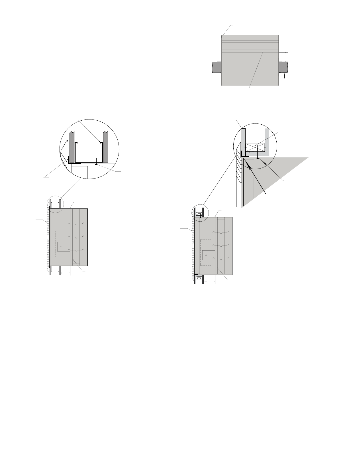
Figure 1 shows two approved installations for
combination fire smoke dampers: 1) “Through the
grille access” and 2) installation in continuing duct.
To provide “through the grille” access to the damper
actuator, the damper is located toward the back of the
sleeve and the actuator is installed between the damper
and grille. Actuator and damper can be accessed and
serviced by removing the grille. To provide access to the
damper actuator for continuing ductwork, refer to the
requirements of NFPA 90A.
Wooden Stud Construction
“Duct Continues”
Horizontal or Vertical Mount
Gypsum Wallboard
Retaining Angle
(Refer to section 4)
Factory Supplied
Thermal Blanket
Stud or Runner
In wood stud construction,
gypsum wallboard must cover
all wood stud surfaces.
#10 sheet metal screws, 2
1/2 inches long, spaced
6 in. on center and
maximum of 2 in. from
corners (minimum of 2
screws per side). Screw
into rear portion of the
studs so as to avoid
space conflicts with
the grille assembly.
Note: Both installations for vertical mount.
Figure 1: Installation configurations for ‘Out of Wall’ combination fire smoke dampers.
ODFD-XXX, OFD-XXX, and OSSFD-XXX: Figure 2
shows installations that are also approved for curtain fire
dampers. For access to inspect the damper and fusible
link, refer to the requirements of NFPA 90A.
Grille
(Supplied
by others)
6 1/2 in.
Max.
Fire damper or
combination fire
smoke damper
“Duct Terminates” Wood Stud“Duct Terminates” Metal Stud
2. CLEARANCE REQUIREMENTS
There is no minimum clearance requirement between
the wall/floor opening and the sleeve exterior (with
thermal blanket attached). However, to facilitate
installation, clearances between the wall/floor opening
and the damper sleeve are recommended. although
there is no maximum allowable clearance, the minimum
overlap requirements between the wall/floor and the
flange/retaining angle must be met. On grill mount
installations the flange must overlap the wall/floor by
½ in. (13mm). On continuous duct installations, the
retaining angles must overlap the wall/floor by 1 in.
(25mm). Because no clearances are required between
the wall/floor opening and the sleeve, dampers may not
be installed in the plane of the wall using this installation
method.
3
Page 4
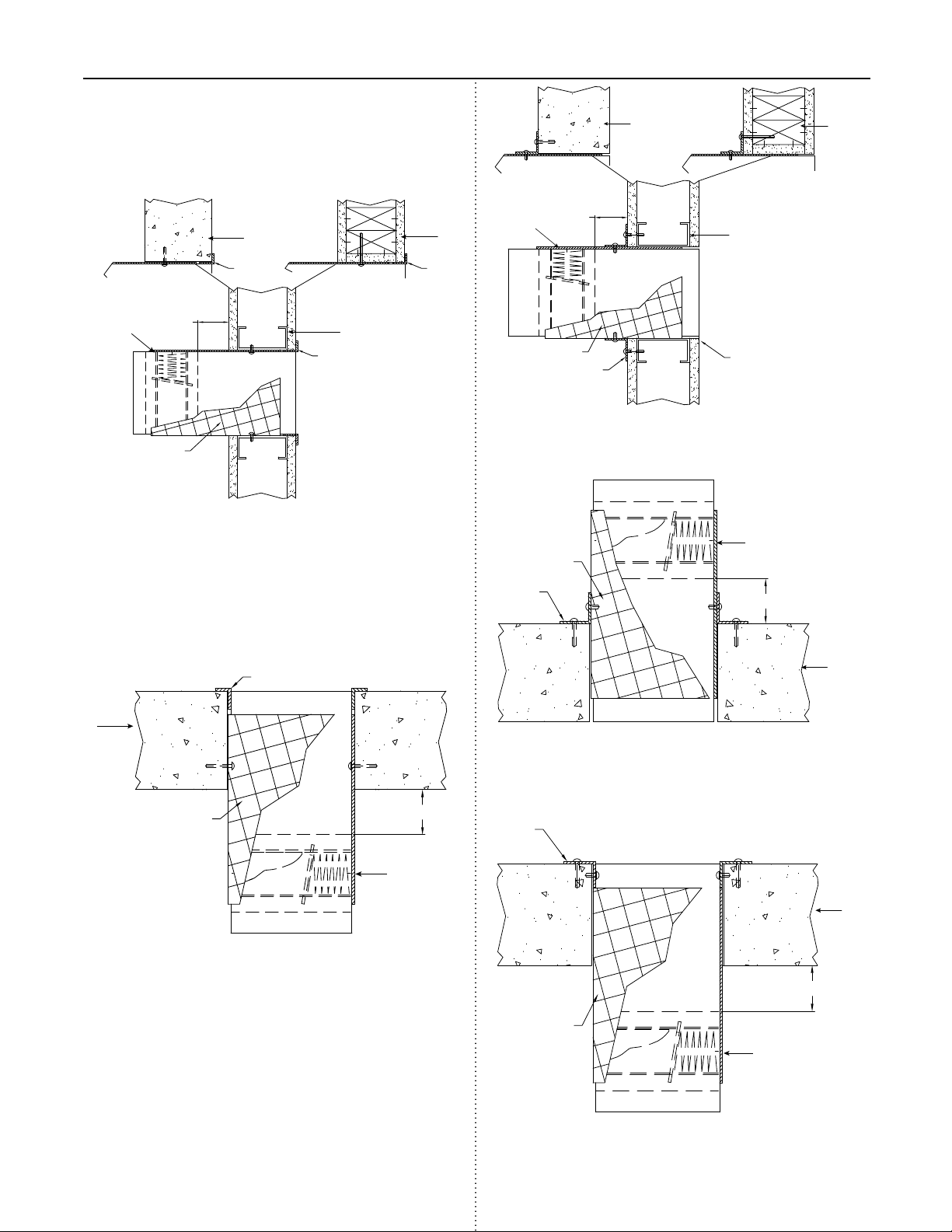
Figure 2
Concrete or
Masonry
Wall
Flange
7 1/2 in. (191mm)
maximum
Damper
Flange
Factory
Supplied
Thermal
Blanket
Type A- Vertical Mount, Duct Terminates
Flange Method
Steel Stud
Wood
Stud
Flange
Concrete or
Masonry Wall
7 1/2 in.
Damper
(191mm)
max.
Factory Supplied
Thermal Blanket
Retaining
Angle
Steel Stud
Alternate
Retaining
Location
Type A- Vertical Mount, Duct Terminates
Single Angle Method
Damper
Factory Supplied
Thermal Blanket
Retaining
Angle
7 1/2 in. (191mm)
Angle
max.
Wood
Stud
Flange
Masonry or
Concrete
Floor
Factory Supplied
Thermal Blanket
7 1/2 in. (191mm)
Damper
Type A - Horizontal Mount Below Floor/Wall, Duct
Terminates Flange Method
max.
Type A - Horizontal Mount Above Floor/Wall,
Duct Terminates Single Angle Method
Retaining
Angle
7 1/2 in. (191mm)
Factory Supplied
Thermal Blanket
Damper
Concrete or
Masonry
Floor
Concrete or
Masonry
Floor
max.
Type A - Horizontal Mount Below Floor/Wall, Duct
Terminates Single Angle Method
4
Page 5

Figure 2 cont...
Masonry or
Concrete Wall
7 1/2 in. (191mm)
Damper
Factory Supplied
Thermal Blanket
Retaining
max.
Angle
Metal
Stud
Retaining
Angle
Type A- Vertical Mount, Thru Duct with Two
Retaining Angles
Damper
Wood
Stud
Concrete or
Masonry Wall
7 1/2 in. (191mm)
Damper
maximum
Factory Supplied
Thermal Blanket
Retaining
Angle
Alternate Retaining
Type A- Vertical Mount, Thru Duct with
Single Retaining Angle
Wood Stud
Angle Location
Damper
Retaining
Angle
Masonry or
Concrete
Floor
Factory Supplied
Thermal Blanket
Type A - Horizontal Mount Above Floor/Wall,
Thru Duct with Two Retaining Angles
Retaining
Angle
Masonry or
Concrete
Floor
Retaining
Angle
Factory Supplied
Thermal Blanket
7 1/2 in. (191mm)
max.
Retaining
Angle
7 1/2 in. (191mm)
max.
Retaining
Angle
Concrete or
Masonry
Floor
Factory Supplied
Thermal Blanket
Type A - Horizontal Mount Above Floor/Wall,
Thru Duct with Single Retaining Angle
Concrete or
Masonry Floor
Factory Supplied
Thermal Blanket
7 1/2 in. (191mm)
maximum
Retaining
Angle
7 1/2 in. (191mm)
maximum
Damper
Type A - Horizontal Mount Below Floor/Wall, Thru
Duct with Two Retaining Angles
Type A - Horizontal Mount Below Floor/Wall, Thru
Duct with Single Retaining Angle
5
Page 6

Figure 2 cont....
Damper
7 1/2 in. (191mm)
maximum
Factory Supplied
Thermal Blanket
Wood Stud
Steel
Stud
Flange
Masonry or
Concrete
7 1/2 in.(191mm)
Maximum
Damper
Metal
Stud
Factory Supplied
Thermal Blanket
Retaining
Angle
Retaining
Angle
Type B2- Vertical Mount, Thru Duct with
Two Retaining Angles
Wood
Stud
Masonry or
Concrete
Type B2- Vertical Mount, Duct Terminates
Flange Method
Flange
Masonry or
Concrete
Factory Supplied
Thermal Blanket
7 1/2 in. (191mm)
maximum
Damper
Type B2 - Horizontal Mount Below Floor/Wall, Duct
Terminates Flange Method
Damper
Factory Supplied
Thermal Blanket
Retaining
Angle
Retaining
Angle
7 1/2 in. (191mm)
maximum
Type B2 - Horizontal Mount Above Floor/Wall,
Thru Duct with Two Retaining Angles
Factory Supplied
Masonry or
Concrete
Thermal Blanket
7 1/2 in. (191mm)
maximum
Retaining
Angle
Masonry or
Concrete
Retaining
Angle
Damper
Type B2 - Horizontal Mount Below Floor/Wall, Thru
Duct with Two Retaining Angles
6
Page 7

Figure 2 cont....
Thermal Blanket
7 1/2 in. (191mm)
Damper
maximum
Factory Supplied
Thermal Blanket
Retaining
Angle
Type B2- Vertical Mount, Duct Terminates
Single Angle Method
Factory Supplied
Thermal Blanket
Retaining
Angle
Concrete or
Masonry
Alternate Retaining
Angle Location
Damper
7 1/2 in. (191mm)
maximum
Metal Stud
Retaining
Angle
Alternate Retaining
Angle Location
Damper
Factory Supplied
Thermal Blanket
7 1/2 in. (191mm)
maximum
Type B2- Vertical Mount, Thru Duct with
Single Retaining Angle
Retaining
Angle
Concrete or
Masonry
Damper
7 1/2 in. (191mm)
maximum
Wood
Stud
Type B2 - Horizontal Mount Above Floor/Wall,
Duct Terminates Single Angle Method
Retaining
Angle
Factory Supplied
Thermal Blanket
Damper
Concrete or
Masonry
Concrete or
Masonry
7 1/2 in. (191mm)
maximum
Concrete or
Masonry
Factory Supplied
Type B2 - Horizontal Mount Above Floor/Wall,
Thru Duct with Single Retaining Angle
Factory Supplied
Thermal Blanket
7 1/2 in. (191mm)
maximum
Retaining Angle
Damper
Concrete or
Masonry
Type B2 - Horizontal Mount Below Floor/Wall, Duct
Terminates Single Angle Method
Type B2 - Horizontal Mount Below Floor/Wall, Thru
Duct with Single Retaining Angle
7
Page 8

Figure 2 cont....
Flange
Metal
Stud
Wood
Stud
Concrete or
Masonry
Damper
Factory Supplied
Thermal Blanket
7 1/2 in. (191mm)
maximum
Type C2- Vertical Mount, Duct Terminates
Flange Method
Factory Supplied
Thermal Blanket
Damper
7 1/2 in. (191mm)
maximum
Metal Stud
Retaining
Angle
Wood Stud
Concrete or
Masonry
Factory Supplied
Thermal Blanket
7 1/2 in. (191mm)
maximum
Retaining
Angle
Type C2- Vertical Mount, Thru Duct with
Two Retaining Angles
Factory Supplied
Thermal Blanket
Retaining
Angle
Damper
7 1/2 in. (191mm)
maximum
Concrete or
Masonry
Flange
Type C2 - Horizontal Mount Above Floor/
Wall, Duct Terminates Flange Method
Flange
Factory Supplied
Thermal Blanket
Concrete or
Masonry
7 1/2 in. (191mm)
maximum
Damper
Retaining
Angle
Type C2 - Horizontal Mount Above Floor/Wall,
Thru Duct with Two Retaining Angles
Retaining
Angle
Retaining
Angle
Factory Supplied
Thermal Blanket
7 1/2 in. (191mm)
Damper
Concrete or
Masonry
Concrete or
Masonry
maximum
Type C2 - Horizontal Mount Below Floor/Wall, Duct
Terminates Flange Method
8
Type C2 - Horizontal Mount Below Floor/Wall, Thru
Duct with Two Retaining Angles
Page 9

Figure 2 cont....
Wood Stud
Metal Stud
Alternate Retaining
Angle Location
Concrete or
Masonry
Factory Supplied
Thermal Blanket
7 1/2 in. (191mm)
maximum
Type C2- Vertical Mount, Thru Duct with
Single Retaining Angle
Factory Supplied
Thermal Blanket
Damper
3. DUCT TO SLEEVE CONNECTIONS
Dampers are supplied with actuators (on applicable
models) and sleeves from the factory and can be
installed without the need for additional field installed
sleeves.
Sleeve gauges of 20-14 (.9mm - 2mm) are to be used.
UL Standard 555 requires all ducts to terminate at fire
damper sleeves. Sleeve thickness must not be less than
the gauge of the connecting duct.
Duct to sleeve breakaway connections must be of the
type described on page 5. Factory furnished round duct
collars on type R and CR dampers are also considered
to be breakaway connections and may be used.
Flange
Thermal Blanket
(installed around entire
outside surface of sleeve)
Retaining
Angle
7 1/2 in. (191mm)
maximum
Concrete or
Masonry
Type C2 - Horizontal Mount Above Floor/Wall,
Thru Duct with Single Retaining Angle
Retaining
Angle
Concrete or
Masonry
7 1/2 in. (191mm)
maximum
Factory Supplied
Thermal Blanket
Damper
Type C2 - Horizontal Mount Below Floor/Wall, Thru
Duct with Single Retaining Angle
Wall
Figure 3: Sleeved damper with Thermal
Blanket (duct termination).
4. SECURING THE DAMPER/SLEEVE ASSEMBLY TO
WALL OPENINGS.
Damper/sleeve assemblies must be installed in wall
openings using flanges and sheet metal screws as
illustrated and described below.
•Flangeonfront(grilleend)ofsleevemustbea
5
minimum of 16 gauge (1.5mm) steel and have a
⁄8 in.
(16mm) minimum flange leg (refer to Figure 3). Using
#10 (19mm) sheet metal screws, screw from inside
of sleeve through the rear portion of the studs (as
shown in Figure 1). Space screws a maximum of 6 in.
(152mm) on center and a maximum of 2 in. (51mm)
from the corners (minimum of 2 screws per side).
No retaining angles are required on the side of wall
opposite from the grille.
•Retaining angles for 1½ hour rated dampers with a
width and height 48 in. (1219mm) or less must be a
minimum of 20 ga. (1mm). Retaining angles for all
3 hour rated dampers and all dampers with a width
or height greater than 48 in. (1219mm) must be a
minimum of 16 gauge (1.5mm). The leg of the retaining
angle on the damper sleeve shall be a minimum of
1¼ in. (32mm). The leg of the retaining angle on the
wall/floor shall be long enough to cover the annular
space and overlap the wall/floor by a minimum of 1 in.
(25mm)(see Figure 4).
9
Page 10

12 in.
24 in. o.c.
Maximum
Floor Runner
Ceiling Runner
24 in. o.c.
Maximum
(metal studs)
24 in. o.c.
Maximum
(metal studs)
16 in. o.c.
Maximum
(wood studs)
16 in. o.c.
Maximum
(wood studs)
2 in. (51mm)
2 in. (51mm)
2 Panhead
Screws
4. SECURING THE DAMPER/SLEEVE ASSEMBLY TO
WALL OPENINGS continued....
•Retaininganglesmustbeattachedtothesleeveusing
one or more of the following methods of attachment:
•Tackorspotwelds
•#10(19mm)sheetmetalscrews
1
•
•
⁄4 in. (6mm) bolts and nuts
3
⁄16 in. (4.7mm) steel pop rivets
Attachments must be spaced a minimum of 6 in.
(152mm) on center and a maximum of 2 in. (51mm) from
corners. The angles must be attached to all 4 sides of
the sleeve. A minimum of two attachments are required
on each side, top and bottom. The angles need not be
attached to each other at the corners.
Caution! Do not tear the thermal blanket during
installation.
Dampers are tested for correct operation and are
square and straight before shipment from the factory.
Dampers must be installed square and straight and
must not be twisted or racked. Failure to install the
damper square and straight may prevent the damper
blades from operating open and closed.
Retaining Angle
Thermal Blanket
(installed around
entire outside
surface of sleeve)
2 in. Max.
6 in. Max.
6 in. Max.
2 in. Max.
Wall
Figure 4: Sleeved damper with Thermal
Blanket (duct continuation).
Note: Thermal blanket is riveted to the damper sleeve and
the seam is taped with acrylic adhesive tape, FSK facing
tape 152 5CWnt, manufactured by Venture Tape Company.
5. ACTUATOR CONNECTIONS
Electrical and/or pneumatic connections to damper
actuators should be made in accordance with wiring
and piping diagrams developed in compliance with
applicable codes, ordinances and regulations (see
Electrical Guidelines).
6 Recommended Preparation of Openings in
Wood and Metal Stud Walls
•Framewallopeningsasshown(seeFigure 5)
•Doubleverticalstudsarenotrequiredforopenings36
in. x 36 in. (914mm x 914mm) or smaller.
•Gypsumwallboardmustbefastened12in.(305mm)
on center to all stud and runner flanges surrounding
opening (see Figure 5).
•Allconstructionandfastenersmustmeetthe
requirements of the appropriate wall design (See UL
Fire Resistance Directory) and/or local codes.
Figure 5
10
Page 11

Breakaway Connections
Drive Slip Joint
6 in.
Std. Clip
Length
60 in. Duct
4 Req’d.
48 in. Duct
3 Req’d.
36 in. Duct
3 Req’d.
24 in. Duct
2 Req’d.
Clip Spacing
6 in. 6 in.
9 in.
7 in.7 in.
5 in. 5 in.
5 in.5 in.
Duct End
Traditional Breakaway Style Transverse Joints
Transverse joints illustrated at right have always been
approved as breakaway connections. SMACNA testing
has also approved the following variations as breakaway
connections.
•Thebreakawayconnectionsshown(Figure 7)
can be applied with maximum of two #10 (19mm)
sheet metal screws on each side and on the
bottom located in the center of the slip pocket and
penetrating both sides of the slip pocket.
•Transversejointsillustrated
can be applied as top and
bottom joints with Drive Slip
- side joints in duct heights
up to 20 inches (508mm)
See Figure 6.
Figure 6
Plain “S” Slip Hemmed “S” Slip Double “S”Slip
Inside Slip Joint Standing “S” Standing “S” (Alt.)
Standing “S” (Alt.) Standing “S” Standing “S”
(Bar Reinforced) (Angle Reinforced)
Figure 7
Round and Oval Duct Breakaway Connections
Round or flat oval ducts connected to Type R or O damper
collars shall be attached with #10 (19mm) sheet metal
screws as follows:
•Ductsto22in.(558mm)wide(ordia.)andsmaller
shall have three screws.
•Ductslargerthan22in.(558mm)wide(ordia.)upto
and including 36 in. (914mm) wide (or dia.) shall have
five screws.
NOTE: All breakaway connections described may have duct
sealant applied, PA2084T duct sealant adhesive
manufactured by Precision, DP1010 water base duct
sealant manufactured by Design Polymetrics, Grey Pookie
or Ductmate PROseal® in accordance with SMACNA
recommendations.
Manufactured Flanged System Breakaway
Connections
Flanged connection systems manufactured by Ductmate,
Ward, and Nexus are approved as breakaway connections
when installed as illustrated (Figure 8).
Proprietary Flange System Breakaway Connections
(TDC by Lockformer, TDF by Engle)
TDC and TDF systems are approved as breakaway
connections when installed as described in the TDC
or TDF addendum to the SMACNA Duct Construction
Standards except the corners may not be bolted.
Standard 6 in. (152mm) metal
clip may be used with spacing
as shown in Figure 9. 3/8 in.
(9.5mm) metal bolts and nuts
may be used to fasten together
Sleeve
Duct
corner pieces (see Figure 10).
Typical TDC/TDF joint
Fire Damper Sleeve
6 in. long 1/16 in. max.
thickness plastic cleats;
12 in. c-c (min. 1 per side)
Flanged system angles
(Attach per
manufacturer's
instructions)
Do not bolt corners
Neoprene gasket
between all angles
Duct
Figure 8
60 in. Duct
4 Req’d.
48 in. Duct
3 Req’d.
36 in. Duct
3 Req’d.
Clip Spacing
6 in.
24 in. Duct
2 Req’d.
18 in. Duct &
Smaller
1 Req’d.
5 in. 5 in.
Std. Clip
Length
6 in. 6 in.
C
L
Duct
9 in.
7 in.7 in.
5 in.5 in.
Figure 9: Detail of proprietary flanged system
breakaway connections.
Flange
Corner Piece
3/8 in. bolt
(optional)
Figure 10
11
Page 12

Damper Maintenance
Dampers do not typically require maintenance as long as they are kept dry and clean. If cleaning is necessary, use mild
detergents or solvents. If lubrication is desired for components such as axle bearings, jackshaft bearings and jamb
seals, do not use oil-based lubricants or any other lubricants that attract contaminants such as dust.
Dampers and their actuator(s) must be maintained, cycled, and tested a minimum in accordance with:
• ThelatesteditionsofNFPA80,90A,92A,92B,101,105,UL864,AMCA503-03andlocalcodes.
• Actuatormanufacturerrecommendations.
Damper Troubleshooting
The following is a possible cause and correction list for common concerns with the dampers.
Symptom Possible Cause Corrective Action
Damper does not
fully open and/or
close
RRL or TOR sensor
tripped
Damper does not
operate
Frame is 'racked' causing blades
to bind on jamb seals
Actuator linkage loose Close damper, disconnect power, adjust and
Defective motor Replace
Screws in damper linkage Damper installed too far into wall. Move out
Contaminants on damper Clean with a non-oil based solvent (see
Heat Push reset button located on backside of
No power supplied to the actuator Add power supply
Adjust frame such that it is square and plumb
tighten linkage
to line as designated on damper label
Damper Maintenance)
RRL or TOR
12
Copyright © 2011 Greenheck Fan Corporation
461337 OFSD ODFD Rev 11 October 2011
 Loading...