

Page 1
MF41-60xx Series
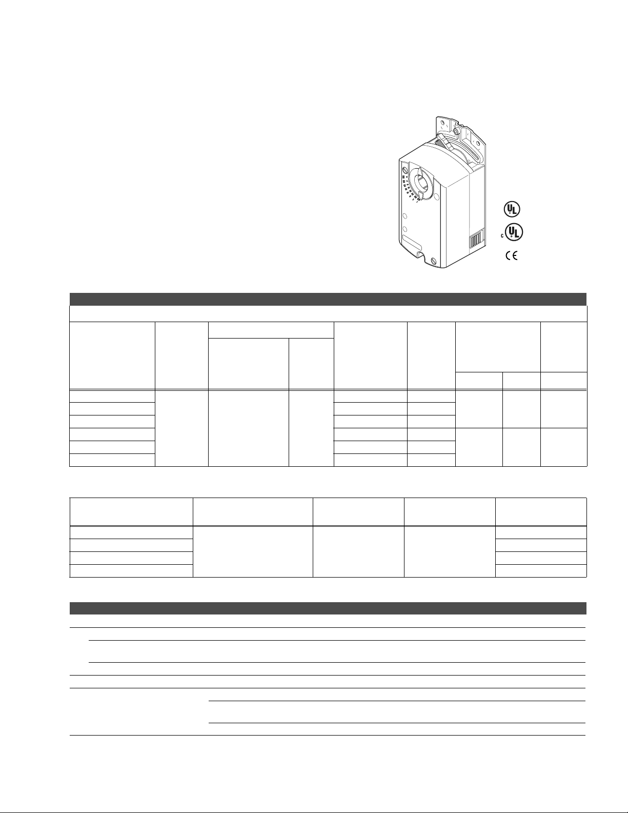
Non-Spring Return DuraDrive® Floating Actuator
The DuraDrive direct coupled 24 Vac non-spring
return rotary electric actuators are designed for
three-position (floating) control of dampers.
ies
-60xx
Features:
• Compact, lightweight design.
• Manual override.
• Factory pre-positioned at 5
q from 0 to assure damper or
0
9
45
0
9
valve close-off.
• Plenum cabling.
• Feedback potentiometer models available.
• cUL and UL listed; plenum versions also CE certified.
• Independently adjustable dual auxiliary switches available.
Model Chart
Damper Actuators.
Actuator Power Input
Model No. Shaft Size
MF41-6043
Voltage
VA
Running
With
Potentiometer
No No
3/8 to 5/8 in.
MF41-6043-502 No Two
MF41-6083 No No
dia.
1/4 to 1/2 in.
24 VAC
+20%-15%
2.3
sq.
MF41-6083-502 No Two
SPDT
Auxiliary
Switches
US
LISTED
Approximate Timing in
Seconds @ 70°F (21°C)
with No Load
50 Hz 60 HZ
108 90 35 (4)MF41-6043-510 Yes No
150 125 70 (8)MF41-6083-510 Yes No
Output
Torque
Rating
lb.-in.
(N-m)
Minimum
Valve Actuator plus LInkages.
Model No.
a
Linkage (included)
Voltage 50/60 Hz
Running
VA
SPDT Aux. Switches
MF41-6043-200
MF41-6043-202 Yes
MF41-6083-200 No
AV-603
24 Vac
+ 20% -15%
2.3
MF41-6083-202 Yes
a
Refer to Valve Catalog, F-27384, for correct applications.
Specifications
Inputs
Control signal Floating three position control, 24 Vac.
Power
Connections 3 ft. (0.9 m) long, 18 AWG leads, plenum-rated.
Outputs
24 Vac +20/-15% 50/60 Hz. Power Consumption: 2.3 VA
MF41-6083: 24 Vac +20/-10% at 90 to 130°F (32 to 55°C) ambient.
MF41-60xx-510: Feedback potentiometer: 0 to 1000: < 10 mA.
MF41-60xx-502: Auxiliary switch contact rating, AC rating: 24 V
ac, 4A Resistive, 2A Inductive. DC
Rating: 12 to 30 Vdc, DC 2A.
Switching Hysteresis: 2
°
No
107
Page 2

MF41-60xx Series
Specifications (Continued)
Environment
Ambient temperature limits
Humidity 5 to 95% RH, non-condensing.
Locations NEMA 2, IP54 to EN60529.
Dimensions 5-7/16 H x 2-3/4 W x 2-3/8 D in. (140 x 70x 60 mm).
Agency Listings
UL UL-873, Underwriters Laboratories.
European Community EMC Directive (89/336/EEC). Emissions (EN50081-1). Immunity (EN50082-2).
CUL Canadian Standards C22.2 No. 24-93.
General Instructions Refer to F-27213.
Accessories
Model No. Description
AM-726 Rotary to linear bracket.
AM-727 Rotary to linear crank arm adaptor
AM-728 Conduit adaptor.
AM-729 3/8 in. shaft adaptor.
AV-603 Valve linkage for VB-7xxx 1/2 to 2 in.
Shipping and Storage: -40 to 158qF (-40 to 70qC).
Operating: -25 to 130qF (-32 to 55qC).
Typical Applications
24 Vac
1
Transformer
Line
Volts
Feedback Potentiometer
MF41-60x3-510
Neut
Auxilary Switch 1
MF41-60x3-502
Auxilary Switch 2
MF41-60x3-502
Figure 1 Typical Wiring Diagram for MF41-60x3-2xx Floating Actuators.
24 Vac
Red
Violet
Orange
P1 Feedback 0-100% P1 - P2, Black
P2 Feedback Common, Black
P3 Feedback 100 to 0% P3- P2, Black
2
CCW
S1 Common, Black
S2 N.C., Black
S3 N.O., Black
S4 Common, Black
S5 N.C., Black
S6 N.O., Black
CW
(1)
(6)
(7)
MF41-60x3
1000
1 Provide overload protection
and disconnect as required.
Earth Ground isolating class 2
Transformer.
CE: Safety Isolating
Transformer per EM 60742
2 Actuators are provided with
color coded wires. Wire
numbers are provided for
reference.
108
Page 3

6153
ies
MF41-6153 Series
Non-Spring Return DuraDrive® Three Position Actuator
The DuraDrive direct-coupled, 24 Vac, non-spring
return electronic actuator is designed for threeposition control of building HVAC dampers.
Features:
• Synchronous motor technology with stall protection.
• Unique self-centering shaft coupling.
• Manual override.
• 133 lb-in (15 Nm) torque.
• Factory pre-positioned at 5
valve close-off.
• Mechanical range adjustment capabilities.
-
• Offset and span adjustment models available.
• Built-in 1/2-inch conduit connection.
q from 0 to assure damper or
US
LISTED
Model Chart
Damper Actuators.
Model No. Shaft Size Motor Type
MF41-6153
Valve Actuator plus LInkages.
Model No.
MF41-6153-200 AV-605
MF41-6153-220 AV-607
a
Refer to Valve Catalog, F-27384, for correct applications.
1/4 to 3/4 in. dia.
1/4 to 1/2 in.sq.
a
Synchronous
Linkage (included)
Power Input @ 50/60 Hz
SPDT
Voltage
24 Vac
+ 20% - 15%
Running
VA W 50 Hz 60 Hz
33 No 150125
Auxiliary
Switches
Running
Voltage 50/60 Hz
W
24 Vac ± 20% 3 3 No
Approximate
Timing in
Seconds @ 70oF
o
(21
C) with No
Load
VA
Specifications
Inputs
Control signal Floating three position control, 24 Vac.
Power All 24 Vac circuits are Class 2. 24 Vac +20/-15% @ 50/60 Hz. Running VA: 3 @ 3 W.
Connections 3 ft. (0.9 m) long, 18 AWG leads.
Electrical Timing: 150 seconds @ 50 Hz; 125 seconds @ 60 Hz.
Output torque rating: 133 lb-in. (15 N-m).
Mechanical
Stroke: Normal angle of rotation is 90q, limited to a maximum of 95q. Field
either end of stroke.
Position indicator: Adjustable pointer is provided for position indication.
Output Torque
Rating
lb-in (Nm)
133 lb-in
(15 Nm)
SPDT Aux.
Switches
adjustable to limit travel on
109
Page 4

MF41-6153 Series
Specifications (Continued)
Environment
Ambient temperature limits
Humidity 5 to 95% RH, non-condensing.
Locations NEMA Type 1, IP54 According to EN 60 529.
Dimensions 8-3/8 H x 3-1/4 W x 2-2/3 D in. (210 x 80 x 70 mm).
Agency Listings
UL UL-873, Underwriters Laboratories.
European Community EMC Directive (89/336/EEC). Emissions (EN50081-1). Immunity (EN61000-6-2).
CUL Canadian Standards C22.2 No. 24-93.
General Instructions Refer to F-27215.
Accessories
Model No. Description
AV-605 Valve linkage for VB-7xxx 1-1/2 to 2 in.
AV-607 Valve linkage for VB-9xxx 2-1/2 to 4 in.
Typical Applications
Operation: -25 to 130qF (-32 to 55qC)
Storage: -40 to 158qF (-40 to 70qC).
1
Line
Volts
24 Vac
Transformer
SPDT Floating
Controller
Red
Violet
Orange
1
6
7
MF41-6153
CW
CCW
Figure 1 Typical Wiring Diagram for MF41-6153 Floating Actuators.
110
Page 5

MF41-6343
6343
Non-Spring Return DuraDrive® Floating Actuator
For non-spring return applications that require
floating control of dampers and valves in HVAC
systems.
Features:
• Direct mount to round or square damper shaft.
• 300 lb.-in. (34 N-m) torque rating.
• Overload protection throughout rotation.
• Oil immersed gear train provides continuous lubrication.
• NEMA 4 housing (IEC IP56).
• Manual override to allow positioning for installation and
manual operation.
-
• Provide floating point control (drive open-hold-drive
closed).
Model Chart
Damper Actuators.
US
Actuator Power Input
Model No.
MF41-6343
a
Optional AM-753 damper shaft mounting clamps for 5/8 in. square or 3/4 to 1 in. round shafts.
Valve Actuator plus LInkages.
Model No.
MF41-6343-230 AV-609 24 Vac ± 20% 3.8 7.1 3.6 No
a
Refer to Valve Catalog, F-27384, for correct applications.
Damper Shaft
3/8 to 1/2 in.
round or square
a
a
Size
Linkage (included)
Voltage
5-/60 Hz
24 Vac
± 20%
Voltage 50/60
Watts
3.8 7.1 3.6 No <145 300 (34) 600 (68)
Hz
VA
Running Holding
VA W Minimum
W
SPDT
Auxiliary
Switches
Running
Approximate
Timing in
Seconds @ 70°F
(21°C) with No
Load
VA
Holding
VA
Output Torque
Rating
lb.-in. (N-m)
Maximum
SPDT Aux.
Switches
Specifications
Inputs
Control signal SPDT floating control input, triacs (500 mA rated) or 2 SPST contacts.
Power Refer to Model Chart. All 24 Vac circuts are Class 2.
Connections 24 in. (61 cm) appliance cables. Conduit connector for M20 metric conduit use AM-756 adapter.
Outputs
Motor Type Brushless DC.
gh reverse mounting.
Mechanical
Direction of rotation: CW or CCW rotation is available throu
Dual shaft clamp: Direct coupled using a through hole output hub. 3/8 to 1/2 in. round or square shafts
standard.
Position indicator: Pointer and scale numbered from 0 to 95q.Stroke 93q ±1q. See Accessories for
larger shaft sizes.
Stall
111
Page 6

MF41-6343
Specifications (Continued)
Environment
Ambient Temperature limits
Humidity 5 to 95% RH, non-condensing.
Locations NEMA 1, NEMA 4 (IEC IP56) with customer supplied water tight connectors.
Agency Listings
UL
European Community EMC Directive (89/336/EEC). Low Voltage Directive (72/23/EEC).
CUL Canadian Sta
Australia
General Instructions Refer to F-26744.
Accessories
Model No. Description
AM-674 Weather shield.
AM-676 Universal shaft extension, approximately 9-1/2 in. long (242 mm) for use on 3/8 to 11/16 in. (10 to 17 mm)
AM-751 Standard anti-rotation bracket 9 in. long x 13/16 in. wide (229 x 21 mm ), included with actuator.
AM-752 Optional anti-rotation bracket 4 in. long x 1-11/16 in. wide (102 x 43 mm), for n
AM-753 Damper shaft mounting clamps for 5/8 in. square shaft, 3/4 in. and 1 in. round shafts (two per package).
AM-754 Standard universal mounting clamps for 3/8 to 1/2 in. (10 to 13 mm) round and square shafts, two included
AM-755 Manual override crank.
AM-756 Metric condu
AV-609 Valve linkage for VB-9xxx 5 and 6 in.
Shipping and Storage: -40 to 160qF (-40 to 71qC).
Operation: -25 to 140qF (-32 to 60qC).
UL-873, Underwriters Laboratories Listed (File #9429 Category: Temperature-Indicating and
Regulating Equipment).
ndards C22.2 No. 4-93.
This product meets requirements to bear the C-Tick mark according to the terms specified by the
Communications Authority under the Radio Communications Act 1992.
round shafts, 3/8 to 9/16 in. square shafts. (AM-753 clamps required).
arrow spaces.
with actuator.
it adaptor M20 x 1.5 t o 1/2 in. NPT (two per package).
Typical Applications
1
24 Vac
3
Red
White
Black
Black
Black/Blue
4
CCW
CW
COM
24H
24G
GRDGreen/Yellow
MF41-6343
2
1 SPDT Floating or Switch/Controller or 2 SPST.
2 Unused conduit port must remain plugged with a water tight pipe plug as
shipped from factory to maintain NEMA Type 4 or IP56 rating.
3 Ground wire may be Green on some models.
4 As viewed from Left (L) side.
Figure 1 Typical SPDT Controller Wiring Diagram.
112
 Loading...