

Page 1
ICD-44
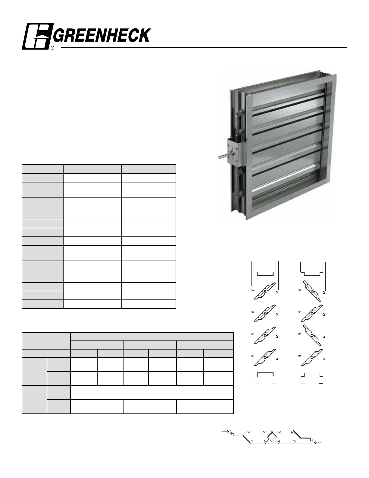
Thermally Broken Blade
Application and Design
Insulated Control Damper
The ICD-44 is a low leakage thermally insulated damper with extruded
airfoil blades. ICD-44 features thermally broken blade to eliminate the
transfer of heat or cold penetration and reduced condensation. Its also
IECC (International Energy Consumption Code) compliant with a leakage
rating of 3 cfm/ft
2
@ 1 in. wg (55 cmh/m2 @ .25 kPa) or less.
Ratings
Pressure: Up to 8.0 in. wg (2 kPa) pressure
differential
Velocity: 2500 to 4000 fpm (12.7 m/s - 20.3 m/s)
Leakage: 3 cfm/ft2@ 1 in. wg at -40°F
(54.8 cmh/m
6 cfm/ft2 @ 4 in. wg at -40°F
(110 cmh/m
Temperature: -70°F to 200°F (-56°C to 93°C)
Standard Construction Optional Construction
Frame Material Aluminum -
Frame Material
.125 in. (3.2mm) -
Thickness
Frame Type 5 in. x 1 in.
(127mm x 25mm)
Hat Channel
Blade Action Opposed Parallel
Blade Material Extruded Aluminum -
Blade Type Thermally Broken Airfoil -
Linkage Plated Steel Out of
Airstream
Axle Bearings Dual Bearing With Acetal
Inner Sleeve, Flanged
Outer Bearing
Axle Material Plated Steel 304SS
Blade Seals Silicone -
Jamb Seals 304SS Silicone
2
@ .25 kPa at -40°C)
2
@ 1 kPa at -40°C)
Single Flange
Reverse Flange or
Quick Connect
304SS
-
1/2 in.
(13mm)
1/2 in.
(13mm)
1/2 in.
(13mm)
1/2 in.
(13mm)
Size Limitations
in. (mm)
W x H
Blade Action Parallel Opposed Parallel Opposed Parallel Opposed
Internal
Minimum
Sizes
Maximum
Sizes
Installation instructions available at www.greeenheck.com
Mount
External
Mount
Single
Section
Multi-
Section
Channel Quick Connect Single or Reverse Flange
12 x 7
(305 x 178)
8 x 7
(203 x 178)
144 in. W x 148 in. H
(3658mm x 3759mm)
12 x 12
(305 x 305)
8 x 12
(203 x 305)
Frame Type
12 x 6
(305 x 152)
8 x 6
(203 x 152)
(1219mm x 1880mm)
96 in. W x 148 in. H
(2438mm x 3759mm)
(305 x 254)
(203 x 254)
48 in. W x 74 in. H
12 x 10
8 x 10
12 x 7
(305 x 178)
8 x 7
(203 x 178)
144 in. W x 148 in. H
(3658mm x 3759mm)
12 x 12
(305 x 305)
8 x 12
(203 x 305
Thermal
Isolation
Break
5 in.
(127mm)
Parallel
Blade
5 in.
(127mm)
Opposed
Thermal
Isolation
Break
Page 2
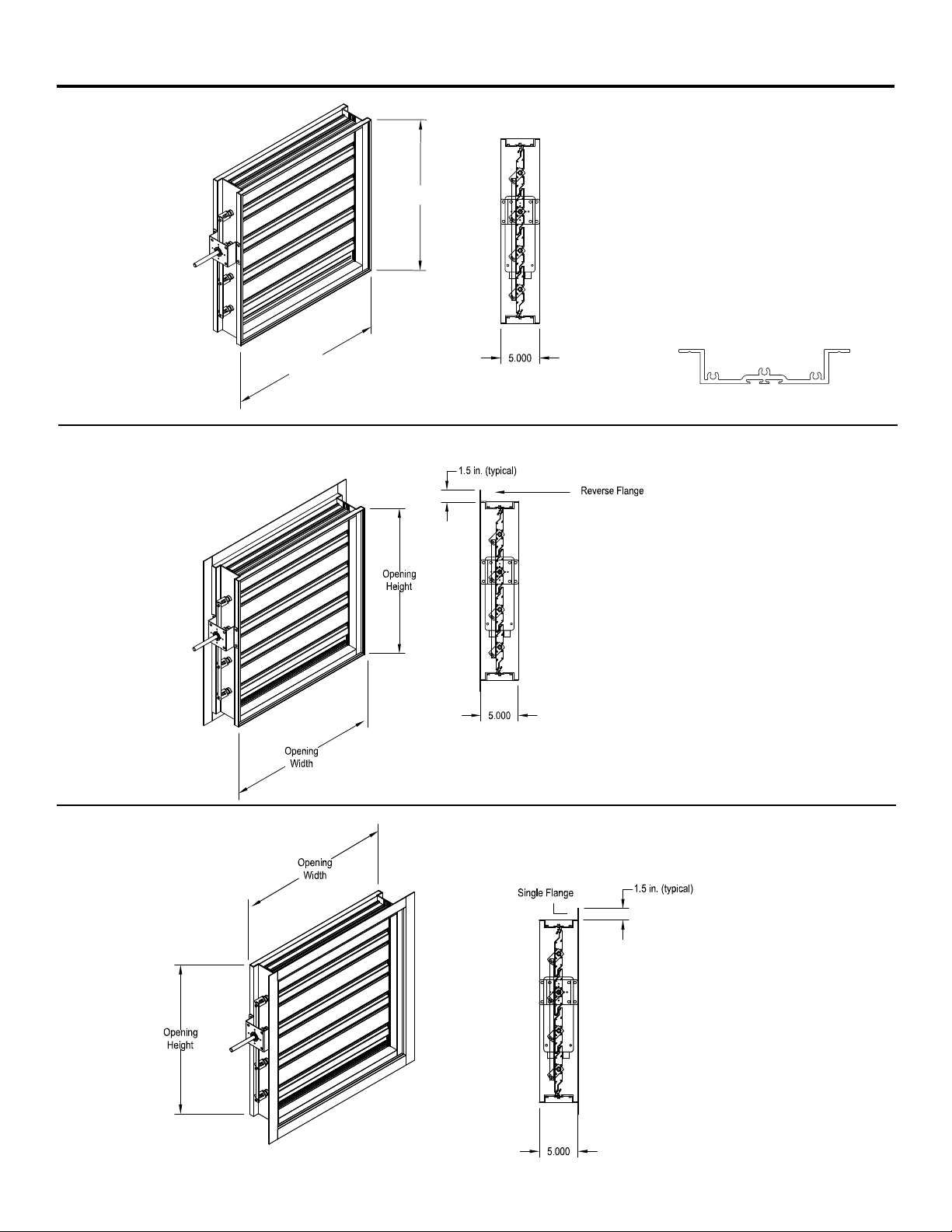
Frame Type Options ICD-44
Channel Frame
Reverse Flange
Opening
Width
Opening
Height
* Width and height is based on outside
dimension. W & H dimensions furnished
approximately 1/4 in. (6mm) undersize.
* Width and height is based on outside
dimension. W & H dimensions furnished
approximately 1/4 in. (6mm) undersize.
Single Flange
* Width and height is based on outside
dimension. W & H dimensions furnished
approximately 1/4 in. (6mm) undersize.
Page 3
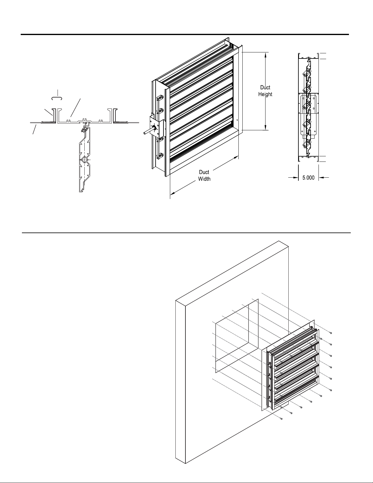
Frame Type Options ICD-44
Quick Connect
1 3/8 in.
Ductmate,
TDC or TDF
Duct
Cleat
Quick
Connect
Frame
Note: When ordering the Quick Connect Frame, size is based on
duct size (or inside dimension of the damper frame). Quick Connect
frame is actual size.
There are applications that require mounting an ICD-44 into a
plenum wall. This illustration depicts how to mount an ICD-44 into a
plenum wall.
1 3/8 in.
Page 4

Pressure Drop Data ICD-44
5D 6D
5D
D
4 (W) (H
)
3.14
This pressure drop testing was conducted in accordance with AMCA Standard 500-D using the three configurations shown. All
data has been corrected to represent standard air at a density of .075 lb/ft3 (1.201 kg/m3).
Actual pressure drop found in any HVAC system is a combination of many factors. This pressure drop information along with an
analysis of other system influences should be used to estimate actual pressure losses for a damper installed in a given HVAC
system.
AMCA Test Figures
Figure 5.3 Illustrates a fully ducted damper. This configuration has the lowest pressure drop of the three test configurations
because entrance and exit losses are minimized by straight duct runs upstream and downstream of the damper.
Figure 5.2 Illustrates a ducted damper exhausting air into an open area. This configuration has a lower pressure drop than
Figure 5.5 because entrance losses are minimized by a straight duct run upstream of the damper.
Figure 5.5 Illustrates a plenum mounted damper. This configuration has the highest pressure drop because of extremely high
entrance and exit losses due to the sudden changes of area in the system.
Page 5

AMCA 5.2 Pressure Drop ICD-44
5D 6D
D
D
=
4 (W) (H)
3.14
Figure 5.3
5D
12 x 12
12 x 12 (305mm x 305mm)
Velocity
(fpm)
500 .03
1000 .11
1500 .25
2000 .45
2500 .71
3000 1.03
3500 1.40
4000 1.83
Pressure
Drop
(in. wg)
24 x 24 (610mm x 610mm)
Velocity
(fpm)
500 .02
1000 .08
1500 .19
2000 .34
2500 .53
3000 .77
3500 1.05
4000 1.37
Pressure
Drop
(in. wg)
36 x 36 (914mm x 914mm)
Velocity
(fpm)
500 .01
1000 .05
1500 .11
2000 .21
2500 .33
3000 .47
3500 .64
4000 .84
Pressure
Drop
(in. wg)
48 x 12
36 x 36
12 x 48
24 x 24
12 x 48 (305mm x 1219mm)
Velocity
(fpm)
500 .01
1000 .06
1500 .14
2000 .25
2500 .40
3000 .57
3500 .78
4000 1.02
Pressure
Drop
(in. wg)
48 x 12 (1219mm x 305mm)
Velocity
(fpm)
500 .03
1000 .14
1500 .32
2000 .57
2500 .89
3000 1.29
3500 1.76
4000 2.30
Pressure
Drop
(in. wg)
Page 6

AMCA 5.3 Pressure Drop ICD-44
5D
6D
12 x 12 (305mm x 305mm)
Velocity
(fpm)
500 .01
1000 .04
1500 .09
2000 .17
2500 .26
3000 .38
3500 .52
4000 .67
Pressure
Drop
(in. wg)
24 x 24 (610mm x 610mm)
Velocity
(fpm)
500 .01
1000 .03
1500 .08
2000 .14
2500 .22
3000 .32
3500 .43
4000 .57
Pressure
Drop
(in. wg)
36 x 36 (914mm x 914mm)
Velocity
(fpm)
500 .01
1000 .02
1500 .04
2000 .08
2500 .12
3000 .18
3500 .24
4000 .32
Pressure
Drop
(in. wg)
48 x 12
12 x 48 (305mm x 1219mm)
Velocity
(fpm)
1000 .02
1500 .06
2000 .10
2500 .17
3000 .24
3500 .33
4000 .43
12 x 48
12 x 12
24 x 24
36 x 36
Pressure
Drop
(in. wg)
500 .01
48 x 12 (1219mm x 305mm)
Velocity
(fpm)
500 .01
1000 .06
1500 .14
2000 .25
2500 .40
3000 .58
3500 .79
4000 1.03
Pressure
Drop
(in. wg)
Page 7

AMCA 5.5 Pressure Drop ICD-44
5D 6D
5D
D
4 (W) (H)
3.14
24 x 24
12 x 48
12 x 12
36 x 36
12 x 12 (305mm x 305mm)
Velocity
(fpm)
500 .05
1000 .23
1500 .52
2000 .93
2500 1.44
3000 2.08
3500 2.83
4000 3.70
Pressure
Drop
(in. wg)
48 x 12
24 x 24 (610mm x 610mm)
Velocity
(fpm)
500 .05
1000 .21
1500 .47
2000 .84
2500 1.32
3000 1.90
3500 2.59
4000 3.39
Pressure
Drop
(in. wg)
36 x 36 (914mm x 914mm)
Velocity
(fpm)
500 .03
1000 .14
1500 .33
2000 .58
2500 .91
3000 1.31
3500 1.79
4000 2.34
Pressure
Drop
(in. wg)
12 x 48 (305mm x 1219mm)
Velocity
(fpm)
500 .04
1000 .18
1500 .42
2000 .74
2500 1.16
3000 1.68
3500 2.28
4000 2.98
Pressure
Drop
(in. wg)
48 x 12 (1219mm x 305mm)
Velocity
(fpm)
500 .05
1000 .22
1500 .51
2000 .90
2500 1.41
3000 2.04
3500 2.78
4000 3.70
Pressure
Drop
(in. wg)
Page 8

Leakage & Specifications ICD-44
Leakage Data
Leakage testing was conducted in accordance with AMCA Standard 500-D and is expressed as CFM/sq. ft. of damper face area.
All data has been corrected to represent standard air at a density of .075 lb/ft3 (1.2 kg/m3).
Leakage
36 X 36
24 X 24
12 X 12
48 X 12
12 X 48
Static Pressure Difference (inches wg)
Specifications
Control Dampers meeting the following specifications shall be
furnished and installed where shown on plans and/or as described in
schedules.
Dampers shall consist of: .125 (3.2mm) aluminum channel frame;
aluminum airfoil blade internally insulated polyurethane foam and
thermally broken. Blades shall be completely symmetrical relative
to their axle pivot point, presenting identical resistance to airflow in
either direction or pressure on either side of the damper. Axle will be
1
⁄2 in. (13mm) diameter plated steel; bearings are dual bearing with
acetal inner sleeve, flanged outer bearing resulting in no metal-tometal or metal-to-plastic contact. Blade seal to be silicone rubber,
jamb seal to be 304SS, and external (out of the airstream) blade-toblade linkage.
Dampers manufacturer’s printed application and performance data
including pressure, velocity, leakage, and temperature limitations
shall be submitted for approval showing damper suitable for
pressures to 8 in. wg (2 kPa), velocities to 4000 fpm (20.3 m/s),
standard air leakage less than 6 cfm/sq. ft. @ 4 in. wg
(110 cmh/m
air performance data shall be developed in accordance with the
latest edition of AMCA Standard 500-D.
Basis of design is ICD-44.
2
@ 1 kPa) and temperatures to 200 °F (93°C). Damper
Copyright ©2010 Greenheck Fan Corporation
ICD-44 Rev. 5 August 2010
 Loading...