

Page 1
Part Number 455602
®
Hooded Propeller Roof Fans
Filtered Supply
Assembly Instructions
Please read these instructions carefully before attempting to assemble the product described. Protect
yourself and others by observing all safety information. Failure to comply with instructions could result
in personal injury and/or property damage!
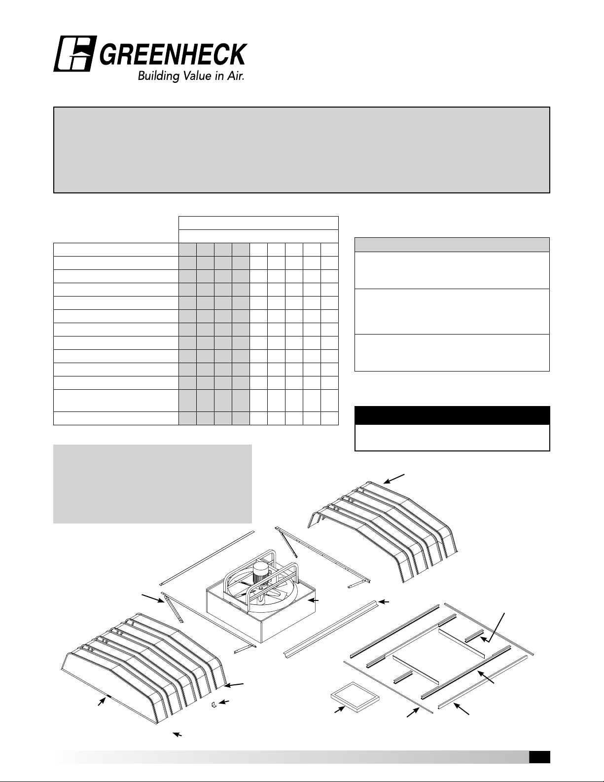
Step 1: Unpack and Inspect Parts
Filtered Supply Fans
Fan Size / Quantity of Parts per Fan Size
Parts Description 20 24 30 36 42 48 54 60 72
Fan / Base Assembly 1 1 1 1 1 1 1 1 1
Hood Support Rail Assembly 2 2 2 2 2 2 2 2 2
Outer Filter Channel 2 2 2 2 2 2 2 2 2
Inner Filter Channel 2 2 2 2 2 2 2 2 2
Filter End Channel 2 2 2 2 2 2 2 4 4
Filter Retaining Angle 2 2 2 2 2 2 2 2 2
End Filter Angle 2 2 2 2 2 2 2 2 2
End Filters 4 4 4 4 4 4 4 6 6
Side Filters 8 8 8 8 8 8 8 10 10
Hood Rails 2 2 2 2 2 2 2 2 2
Hood Enclosure Panels
- 1 male and 1 female panel
Hood Clips for sizes 48 - 72 - - - - - 16 18 20 22
Shaded sizes will always ship fully assembled unless otherwise specified.
4 5 7 7 8 9 10 11 12
Tools required to assemble fans:
• Drill, Electric or pneumatic preferred.
• 3/8”, 7/16”, 1/2”, and 9/16” wrenches and sockets
• 5/16” nut runner bit for drill
• Rubber mallet
• Awl for hole alignment
Each fan that is shipped knocked down has the
following hardware package PN 816529 containing:
Part Number 816529 - Hardware Package includes
Part Number 816526 - Hood Support Fasteners
(16) 3/8” - 16 x 3/4” Spinlock Bolts
(12) 3/8” - 16 Spinlock Nuts
Part Number 816527 - Hood Fasteners
(75) #12 x 3/8” Sheet Metal Screws with Washer
(4) 3/8” - 16 x 1-1/2” Spinlock Bolts
(4) 3/8” - 16 Spinlock Nuts
Part Number 816528 - Birdscreen / Filter Fasteners
(26) 5/16” - 18 x 3/4” Weld Stud Bolts
(26) 5/16” - 18 Spinlock Nuts
Note: Hardware package is designed for the filtered 72inch
fan. When used on smaller sizes, there will be some fasteners
left over.
IMPORTANT
It is recommended that a two man crew
minimum be used for fan/hood assembly.
Hood Enclosure Panel
(Female)
Hood Support Rail
Label
Hood Panels
Hood Clips
(Sizes 48 - 72)
Hood Enclosure Panel
(Male)
Fan Base
Filter
Typical filter channel set is shown.
Quantity of filter end channels
varies by fan size.
Hood Rail
Filter End
Angles
Hooded Propeller Roof Fans • Filtered Supply
Filter End
Channel
Inner Filter
Channel
Outer Filter
Channel
Model
1
1
Page 2
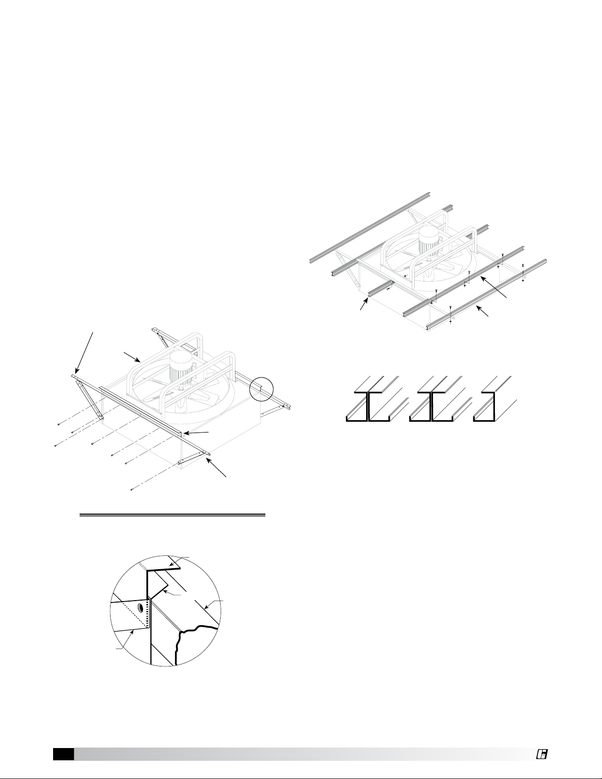
Step 2: Fasten Hood Support Rails
Fan Base
Filter Retainer
Angle
Hood Support
Angle
Fan
Panel
Hardware Required:
Hardware Package Part Number 816526
3/8” - 16 x 3/4” hex head spinlock bolts & nuts
Quantity:
Up to (8) fasteners per side for 72 inch fans; less
required for smaller sizes.
Instructions:
The bolts that fasten the fan panel to the base will
also be used to secure the hood support rails and
lter retaining angles. (see Detail 2).
A. Remove the 3/8” - 16 x 3/4” bolts from ONE
SIDE of the fan panel (up to six bolts for size
72).
B. Assemble the parts and wrench tighten the
hood support rails and lter retaining angles
perpendicular to fan drive frame as shown.
Mounting holes in fan base will line up with
holes in hood support rails and lter retaining
angles.
C. Repeat for opposite side.
Hood support rails
perpendicular to
fan drive frame
Step 3: Install Filter Channels
Hardware Required:
Hardware Package Part Number 816528
5/16” - 18 x 3/4” weld studs and spinlock nuts
Quantity:
As required.
Instructions:
Finger tighten the channels in place as shown.
Bolt hole locations as shown are typical, but
larger units will have additional lter end channel
sections. The detail below will help identify the
correct channel and its proper orientation.
Inner Filter
Filter End
Channel
Channel
Outer Filter
Channel
Fan Drive Frame
Detail 2
Exploded detail
below
Filter Retainer Angle
Hood Support
Angle Assembly
Filter End
Channel
Channel End Profiles
Inner Filter
Channel
Outer Filter
Channel
2
Hooded Propeller Roof Fans • Filtered Supply
®
Page 3

Step 4: Install Filter End Angles
Hardware Required:
Hardware Package Part Number 816528
5/16” - 18 x 3/4” weld studs and spinlock nuts
Quantity:
As required.
Instructions:
A. Finger tighten the end angles in place as
shown. Note correct position of end angle in
Detail 4 with angle leg down and facing the fan
base. Install on both ends.
B. After all lter channels and end angles are
bolted together, square-up assembly and
wrench tighten all fasteners.
Detail 4
Step 5: Install Filters
Instructions:
Slide lters into lter channels as indicated by the
arrows. No fasteners or hardware are required in
this step.
Side
Filters
Filters
End
Side
Filters
Side
Filters
End
Filters
Side
Filters
Step 6: Install Hood Rails
Hardware Required:
Hardware Package Part Number 816527
3/8” - 16 x 1-1/2” hex head spinlock bolts and
nuts
Quantity:
4 sets
Instructions:
A. Position the two hood rails as shown and
finger tighten the fasteners. These fasteners
will be wrench tightened in Step 7 D after the
hood panels are installed and secured.
®
Hooded Propeller Roof Fans • Filtered Supply
3
Page 4

Step 7: Install Hood Panels
Hardware Required:
Hardware Package Part Number 816527
#12 x 3/8” sheet metal screws with washer
Quantity:
75 pcs. required for 72 inch fan; less required for
smaller sizes.
Instructions:
A. Locate the male hood enclosure panel.
This panel has a label that reads: “Male hood
enclosure panel. Start with this assembly rst.”
This is the starter panel. Place this panel on the
hood rails and fasten tight with four (4) screws.
B. Install the intermediate panels one at a time.
The panels have interlocking ribs (see Detail
7A). For fan sizes 48 and larger, hood clips must
also be installed on each panel. Each panel is
predrilled for hood clip installation (see Detail
7B). Secure each hood clip with a screw and
secure each intermediate panel to the hood
rails with four (4) screws.
C. Install the female hood enclosure panel.
Secure this panel to the hood rails with four (4)
screws. To install the hood clips (sizes 48 and
larger), remove the end lters prior to installing
and securing the female hood enclosure panel
to gain access to the underside of the hood.
Reinstall the end lters after hood clips are
installed.
D. Wrench tighten the four (4) bolts that secure
the hood rails to the hood support rails.
Detail 7A
Hood Enclosure Panel
(Female)
Detail 7B
Female Rib
Male Rib
#12 x 3/8" Sheet Metal Screw
with Sealing Washer
Hood Clip
Fan sizes 48 and larger
Two on each interlocking rib
®
Phone: (715) 359-6171 • Fax: (715) 355-2399 • E-mail: gfcinfo@greenheck.com • Website: www.greenheck.com
4 455602 • Filtered Supply, Rev. 2, September 2010 Copyright 2010 © Greenheck Fan Corp
 Loading...