

Greenheck Hooded Propeller Fans Exhaust and Supply User Manual
PN 455601
®
Hooded Propeller Roof Fans
Exhaust and Supply
Assembly Instructions
Please read these instructions carefully before attempting to assemble the product described. Protect
yourself and others by observing all safety information. Failure to comply with instructions could result
in personal injury and/or property damage!
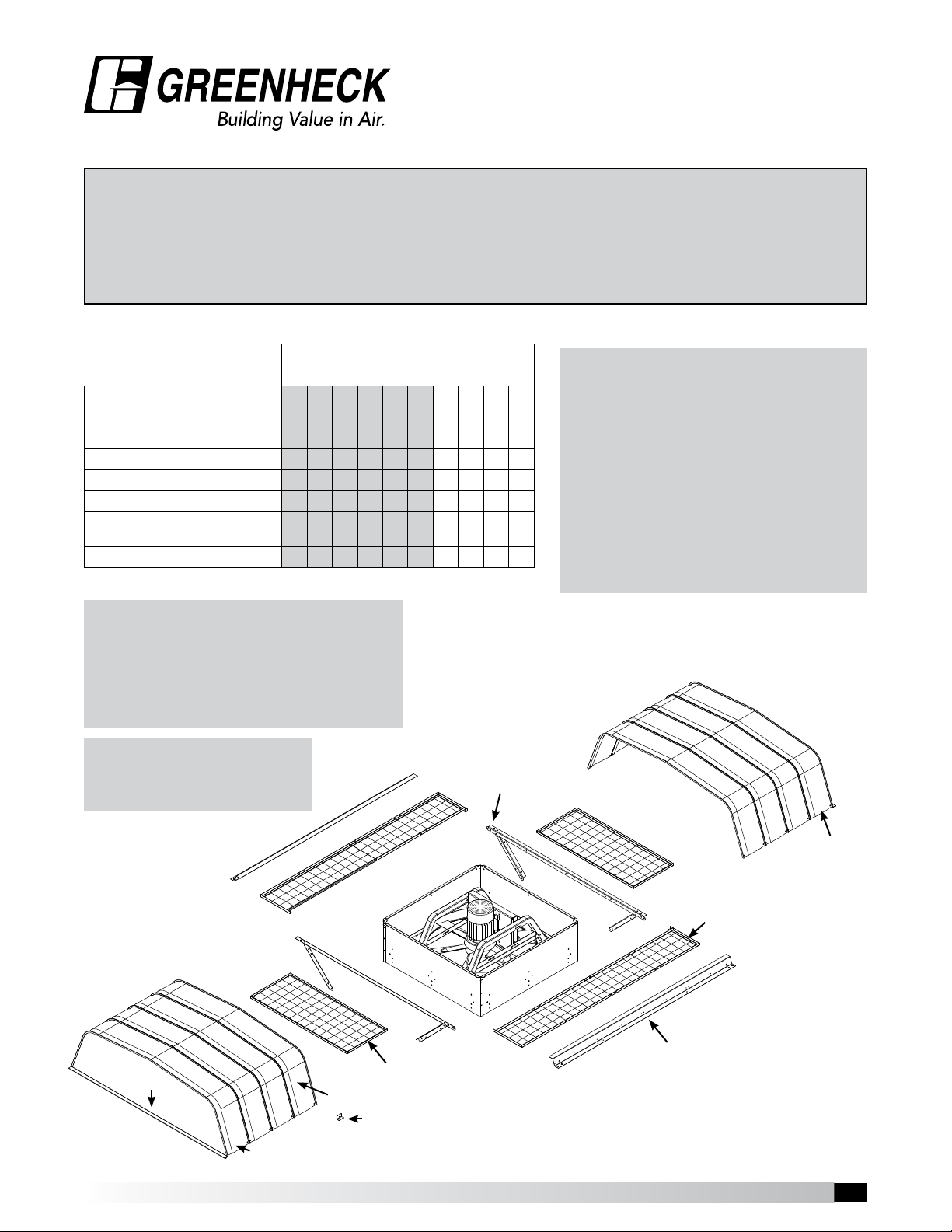
Step 1: Unpack and Inspect Parts
Parts List
Parts Description 18 20 24 30 36 42 48 54 60 72
Fan / Base Assembly 1 1 1 1 1 1 1 1 1 1
Hood Support Rail Assembly 2 2 2 2 2 2 2 2 2 2
Side Birdscreens (Long Screens) 2 2 2 2 2 2 2 2 2 2
Side Birdscreens (Short Screens) 2 2 2 2 2 2 2 2 2 2
Hood Rails 2 2 2 2 2 2 2 2 2 2
Hood Panels including 1 Male &
1 Female hood enclosure panel
Hood Clips for sizes 54 - 72 – – – – – – – 16 18 20
Shaded sizes will always ship fully assembled unless otherwise specified.
Fan Size / Quantity of Parts per Fan Size
4 4 5 6 7 8 9 9 10 11
Exhaust / Supply Fans
Each fan that is shipped knocked down has the
following hardware package containing:
Part # 816529 - Hardware Package
Part # 816526 - Hood Support Fasteners
(16) 3/8” - 16 x 3/4” Spinlock Bolts
(12) 3/8” - 16 Spinlock Nuts
Part # 816527 - Hood Fasteners
(75) #12 x 3/8” Sheet Metal Screws with Washer
(4) 3/8” - 16 x 1-1/2” Spinlock Bolts
(4) 3/8” - 16 Spinlock Nuts
Part # 816528 - Birdscreen / Filter Fasteners
(26) 5/16” - 18 x 3/4” Weld Stud Bolts
(26) 5/16” - 18 Spinlock Nuts
(4) #12 x 3/4” Self-Drilling Screws w/ Washer
Tools required to assemble fans:
• Battery Drill, Electric or Pneumatic preferred.
• 3/8”, 7/16”, 1/2”, and 9/16” Wrenches and Sockets.
• 5/16” Nut Runner Bit for Drill.
• Rubber Mallet.
• Awl for Hole Alignment.
It is recommended that a two man
crew minimum be used for fan/
IMPORTANT!
hood assembly.
Label
Hood
Panels
Hood Clips
(Sizes 54 - 72)
Hood Enclosure Panel
(Male)
Short Birdscreen
Section
Note: Hardware package is designed for the filtered 72” fan.
When used on smaller sizes, there will be some fasteners
left over.
Hood
Support
Rail
Hood
Enclosure
Panel
(Female)
Long Birdscreen
Section
Hood
Rail
Hooded Propeller Roof Fans • Exhaust and Supply
Model
1
1
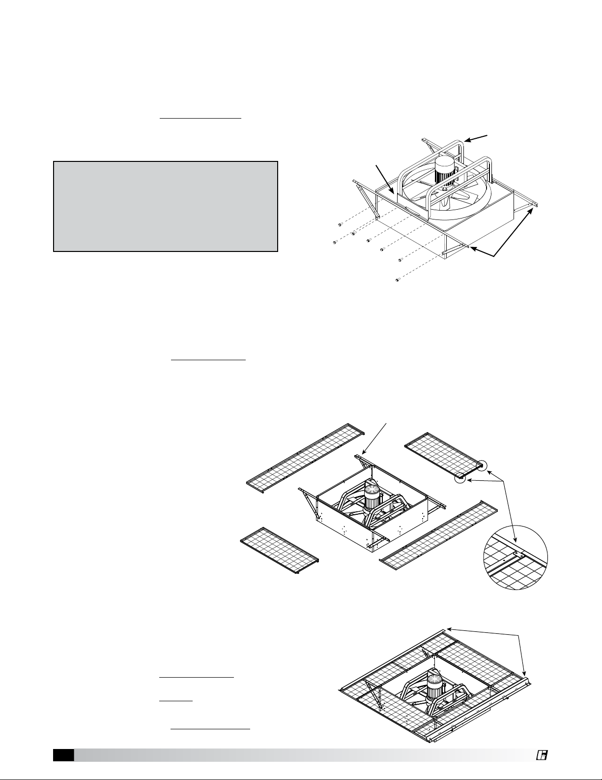
Step 2: Fasten Hood Support Rails
Hardware Required: Hardware Package #816526
3/8” - 16 x 3/4” hex head spinlock bolts & nuts
Quantity: Up to (8) fasteners per side for 72” fans, less required for smaller sizes.
Instructions: WRENCH TIGHTEN the hood support rails to fan base with rails perpendicular
to fan drive frame as shown. Mounting holes in fan base will line up
with holes in hood support rails.
Fan
IMPORTANT!
Panel
Supply Fans (Models RBS, RBCS, RS2, RCS3)
The fan panel bolts are also used for the hood
support rails. Remove fan panel bolts (one
side at a time) and reinstall through the hood
support rails.
Step 3: Install Birdscreen Sections
Hardware Required: Hardware Package #816528
5/16” - 18 x 3/4” weld studs and spinlock nuts
Fan Drive
Frame
Hood support rails
perpendicular to
fan drive frame
Quantity: Only 10 sets required of the 26 sets provided.
Instructions: A) FINGER TIGHTEN the long birdscreen sections to the hood support
rails at the locations indicated using the 10 sets of fasteners.
B) Lay the short birdscreen sections in place and rotate the quick release
fasteners on the underside of the birdscreen to secure. (See Detail 3).
Fastener
Location
Detail 3
Step 4: Install Hood Rails
Hardware Required: Hardware Package #816527
3/8” - 16 x 1-1/2” hex head spinlock bolts and nuts
Quantity: 4 sets
Quick
Release
Fastener
Hood
Rails
Instructions: A) Position the (2) hood rails as shown and
FINGER TIGHTEN the fasteners. These
fasteners will be wrench tightened in
Step 5D after the hood panels are
installed and secured.
B) WRENCH TIGHTEN the fasteners in the
long birdscreen sections.
2
Hooded Propeller Roof Fans • Exhaust and Supply
Detail 4
®
 Loading...