

Page 1
Document 475742
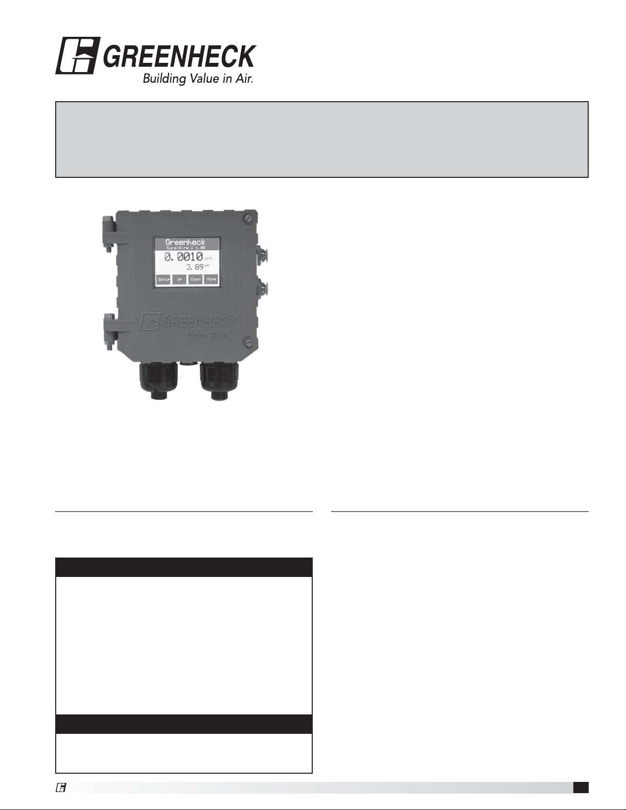
Sure-Aire™ Flow Monitoring System
®
User and Service Manual
Installation, Operation and Maintenance Manual
Please read and save these instructions for future reference. Read carefully before attempting to assemble,
install, operate or maintain the product described. Protect yourself and others by observing all safety
information. Failure to comply with instructions could result in personal injury and/or property damage!
Differential Pressure Controller Features:
• NEMA-4 and IP56 enclosure rating
• Factory calibrated
• 100-240 Vac 50/60 Hz input voltage
• Pressure ranges:
0-8.30 inches W.C.
0-22.14 inches W.C.
0-41.52 inches W.C.
0-83.04 inches W.C.
0-138.40 inches W.C.
• Selectable isolated output transmitter linear to
differential pressure
4-20 mA
2-10 Vdc
• LCD display with user-friendly touch panel interface
• Temperature compensation
• Remote duct temperature sensor
• Programmable elevation
• English or metric readings
• Simple installation
General Information
This instruction manual provides installation, operating,
maintenance, and parts information for Sure-Aire™
Series Differential Pressure Controllers.
WARNING
Improper installation, adjustment, alterations, service
or maintenance can cause injury and property
damage, as well as possible voiding of factory
warranty. No person may install, operate, or maintain
the Sure-Aire Differential Pressure Controller(s)
and transmitters without first being fully trained
and qualified in the installation, operation and
maintenance, and carefully reading and understanding
the contents of this manual. If you have any
questions about these instructions, contact your local
representative.
CAUTION
Risk of electrical shock! More than one disconnect
switch may be required to de-energize the equipment
before servicing.
®
Table of Contents
General Information . . . . . . . . . . . . . . . . . . 1
Differential Pressure Controller Features. . . . . . . . 1
Installation . . . . . . . . . . . . . . . . . . . . . . . 2
Dimensions and Hole Mounting Patterns . . . . . . 2
Wiring and System Components . . . . . . . . . . 2
Label and Order Information . . . . . . . . . . . . 2
Sure-Aire Controller Part Number . . . . . . . . . . 2
Display Setting Options and Setup . . . . . . . . . 3-4
4-20 mA Transmitter Calibration Procedure . . . . . . 5
2-10 Vdc Transmitter Calibration Procedure . . . . . . 6
Temperature Sensor . . . . . . . . . . . . . . . . . . 7
Specifications . . . . . . . . . . . . . . . . . . . . . 7
Maintenance Log. . . . . . . . . . . . . . . Backcover
Our Commitment. . . . . . . . . . . . . . . Backcover
Sure-Aire™ Flow Monitoring System
1
Page 2
Installation
CONFORMS TO
UL STD 61010-2-030
CERTIFIED TO
CAN/CSA STDC22.2 #61010-2-030
Equipment For Measurement
Schofield, WI 54476 U.S.A.
Description: CNTRL,SURE-AIRE,0-22.14”
Fan Model: QEP Fan Size: 36
K Factor: 1967 Elevation: 1100
P/N: 384800 Sales Order: 6606573
Tag Mark: SF-1
P.O.#0843 Date Code: 8/12
100 to 240 Vac
50/60 Hz
Input Power
Earth Ground
Line
Neutral
3/8 A 250 Vac
MEDIUM LAG
3192905
4 to 20 mA/
2-10 Vdc (+)
4 to 20 mA/
2-10 Vdc (-)
Shield
Temperature
Sensor
Load Resistance
200-900 Ohms
WARNING
When wiring the instrument, you must follow industry
standard practices for control and protection against
electrostatic discharge (ESD). Failure to exercise good
ESD practices may cause damage to the controller.
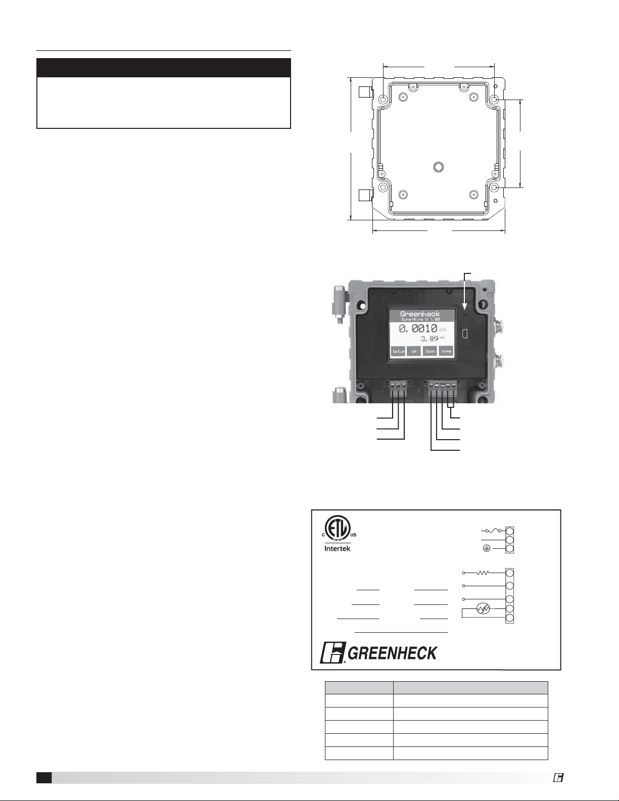
1. Mount the controller in the vertical plane using four
#8-32 screws. Open the front cover by unscrewing
the two captive thumb screws to gain access to the
four mounting locations pictured at right.
Note: Mount the Sure-Aire controller within 75 feet
of the termination plate on the fan.
2. Use 1/4-inch nylon tubing to connect the
corresponding high and low, 1/4-inch quick connect,
pressure ports of the Sure-Aire controller to the high
and low pressure ports of the termination plate on
the fan.
3. Remove terminal block TB1 and perform wiring for
the pins listed below. For liquid tight applications,
use only 1/2-inch liquid tight conduit.
Terminal Block TB1: Input Power
Pin 1 = Line
Pin 2 = Neutral
Pin 3 = Earth Ground
4. Provide power to the controller to turn it on.
5. Select the desired Output Signal of the controller
for the Building Automation System. Use the touch
screen to select the 4-20 mA or 2-10 Vdc output
signal via the controller’s setup menu. (Refer to
Display Setting Options and Setup section, Output
Signal, pages 3 and 4).
6. Wire TB2 appropriately for the selected Output
Signal in Step 5.
Terminal Block TB2: Transmitter/Temperature
Sensor
Pin 1 = 4-20 mA or 2-10 Vdc (+) (output)
Note: 4 to 20 mA requires a load resistor
200-900 ohms
Pin 2 = 4-20 mA or 2-10 Vdc (-) (output)
Pin 3 = Shield
Pin 4 = Remote Temperature Sensor (input)
Pin 5 = Remote Temperature Sensor (input)
Note: Signal isolator may be required when two or
more output signals share a common connection at
the PLC/controller.
7. If temperature compensation is desired, mount the
provided temperature sensor in contact with the
airstream. Wire the temperature sensor into TB2
and change Temperature Comp to “Yes” via the
controller’s setup menu.
8. When the above steps are completed, make sure the
front cover is properly aligned to the housing and the
two captive thumb screws are securely tightened.
Sure-Aire™ Flow Monitoring System
2
Dimensions and Hole Mounting Pattern
4-5/32 in.
(105.6 mm)
5-3/8 in.
(136.5 mm)
5 in.
(127 mm)
3-9/32 in.
(83.3 mm)
Wiring and System Components
Reset Button
High
Pressure
Port
Low
Pressure
Port
Line
Neutral
Earth Ground
TB1 TB2
Temperature Sensor
Shield
4-20 mA / 2-10 Vdc (-)
4-20 mA / 2-10 Vdc (+)
Label and Order Information
The label providing details pertaining to the purchase
order is located on the inside cover of the controller.
TB1
1
2
3
TB2
1
2
3
4
5
Part Number Description
384799 CNTRL,SURE-AIRE,0-8.3
384800 CNTRL,SURE-AIRE, 0-22.14
384801 CNTRL,SURE-AIRE, 0-41.52
384802 CNTRL,SURE-AIRE, 0-83.04
384803 CNTRL,SURE-AIRE, 0-138.40
®
Page 3
Display Setting Options and Setup
Menu Options: Current
settings are displayed
in the main display area
of the screen. To review
current settings, press Up
or Down to scroll through
the various controller
settings as outlined
below. Press Home to
return to the main screen.
• Elevation
• X-Mitter (output signal)
• Software Version
• K-Factor
• Sensor Installed
• Differential Pressure Measurement
• Sure-Air Controller Temperature
• Flow Temperature
• Flow Rate Measurement
• Air Density
The following display setting options can be changed in
the Setup menu of the controller:
Measurement System:
Press Edit to change.
Press Prev or Next to
adjust, then press Enter
to store the value.
• English (default)
• Metric
K Factor: Press Edit to
change K Factor. Press
Inc or Dec to adjust, then
press Enter to store the
value.
• 200 to 30,000
Greenheck
Sure-Aire V 1.00
0.0010 CFM
3.96 mA
Setup Up Down Home
Sure-Aire Controller
LCD Touch Display
Greenheck
Sure-Aire V 1.00
Measurement System:
English
Exit Prev Next
Greenheck
Sure-Aire V 1.00
K Factor:
Exit Inc Dec
Edit /
Enter
200
Edit /
Enter
Pressure Units: Press
Edit to change pressure
units. Press Prev or Next
to adjust, then press
Enter to store the value.
• In WC (default)
• Ft WC
• mm WC
• cm WC
• PSI
• In Hg
• mm Hg
• mBar
• PA
• KPA - kilopascals (1kPa = 1000 Pa)
• HPA - hectopascals (1 hPa = 100 Pa)
• Oz In.
Air Flow Units: Press
Edit to change Air Flow
Units. Press Prev or Next
to adjust, then press
Enter to store the value.
• CFM (default)
• m
• m3/min
Main Display Value:
Press Edit to change
Main Display Value.
Press Prev or Next to
adjust, then press Enter
to store the value.
• Flow (default)
• Pressure
• Temperature
• Air Density
• Output Signal
• None
Secondary Display:
Press Edit to change
Secondary Display. Press
Prev or Next to adjust,
then press Enter to store
the value.
• Flow
• Pressure
• Temperature
• Air Density
• Output Signal (default)
• None
3
/hr
Greenheck
Sure-Aire V 1.00
Pressure Unit:
Exit Prev Next
Greenheck
Sure-Aire V 1.00
Air Flow Unit:
Exit Prev Next
Greenheck
Sure-Aire V 1.00
Main Display Value:
Exit Prev Next
Greenheck
Sure-Aire V 1.00
Secondary Display Value:
Output Signal
Exit Prev Next
In WC
Edit /
Enter
CFM
Edit /
Enter
Flow
Edit /
Enter
Edit /
Enter
®
Sure-Aire™ Flow Monitoring System
3
Page 4

Display Brightness:
Press Edit to change
brightness. Press Inc or
Dec to adjust, then press
Enter to store the value.
• 10 - 100%
(80% default)
Greenheck
Sure-Aire V 1.00
Display Brightness %:
80
Exit Inc Dec
Edit /
Enter
Transmitter Min Value:
Press Edit to change
Transmitter Min Value.
Press Inc or Dec to
adjust, then press Enter
to store the value.
NOTE: See Transmitter
Calibration
Greenheck
Sure-Aire V 1.00
Transmitter Min Value:
1827
Exit Inc Dec
Edit /
Enter
Elevation: Press Edit to
change elevation. Press
Inc or Dec to adjust, then
press Enter to store the
value.
• 0 - 10,000 ft
(0 ft default)
Temperature
Compensation:
Press Edit to
change Temperature
Compensation. Press
Prev or Next to adjust,
then press Enter to store
the value.
• Yes (default)
• No
Note: If temperature compensation is set to ‘No’, the
air density will be a function of standard temperature
(70°F/21°C).
Greenheck
Sure-Aire V 1.00
Elevation:
800ft
Exit Inc Dec
Greenheck
Sure-Aire V 1.00
Temperature Comp:
Exit Prev Next
Edit /
Enter
Ye s
Edit /
Enter
Transmitter Max Value:
Press Edit to change
Transmitter Max Value.
Press Inc or Dec to
adjust, then press Enter
to store the value.
NOTE: See Transmitter
Calibration
Greenheck
Sure-Aire V 1.00
Transmitter Max Value:
720
Exit Inc Dec
Edit /
Enter
Output Signal: Press
Edit to change Output
Signal type. Press Prev or
Next to adjust, then press
Enter to store the value.
• 4-20 mA (default)
• 2-10 Vdc
Note: Output signal
is linear to differential
pressure. The equation
provided on the Sure-Aire label adhered to the fan must
be used to calculate volume.
Greenheck
Sure-Aire V 1.00
Output Signal:
4-20 mA
Exit Prev Next
Edit /
Enter
WARNING
Due to load resistance change from product to
product, it may be necessary to recalibrate the
4-20mA transmitter. See 4-20 mA calibration
procedure.
Sure-Aire™ Flow Monitoring System
4
®
Page 5

4-20 mA Transmitter Calibration
Procedure
WARNING
Due to load resistance change from product to
product, it may be necessary to recalibrate the
4-20mA transmitter.
1.0 Test Equipment
1.1 Digital Multimeter. Set multimeter to read
mA DC
1.2 Load resistor. Select a series Load Resistor
between 200 and 900 ohms.
2.0 Interconnect Wiring
3/8 A 250 Vac
MEDIUM LAG
Line
Neutral
Load Resistance
200-900 Ohms
TB1
100 to 240 Vac
1
50/60 Hz
2
Input Power
3
Earth Ground
TB2
4 to 20 mA/
1
2-10 Vdc (+)
4 to 20 mA/
2
2-10 Vdc (-)
Shield
3
Temperature
4
Sensor
5
Greenheck
Sure-Aire V 1.00
0.0010 CFM
3.96 mA
Setup Up Down Home
Sure-Aire Controller
LCD Touch Display
2.13 Transmitter Max Value.
Greenheck
Sure-Aire V 1.00
Transmitter Max Value:
720
Exit Inc Dec Enter
2.14 Press Edit, then Inc or Dec until the digital
multimeter reads exactly 20.00 mA.
2.15 Press Enter to store the new value.
2.16 Press Exit to return to the main screen.
2.17 4-20 mA transmitter calibration completed.
NOTE
Apply a vacuum to the High Port and the 4-20 mA
transmitter will track the span of the pressure range.
i.e. The Sure-Aire controller with a pressure sensor
of 0 - 41.51 in. W.C. installed, 4.00 mA = 0 in. W.C.,
20.00 mA = 41.52 in. W.C.
2.1 Validate the controller is setup for 4-20 mA output
signal.
2.2 Validate the power is off on the DC power supply
and the Sure-Aire controller.
2.3 Validate the multimeter is set to read mA DC.
2.4 Select a series Load Resistor between 200 and
900 ohms and install one end to TB2-1.
2.5 Interconnect the multimeter (+) probe to the other
end of the load resistor.
2.6 Interconnect the multimeter (-) probe to TB2-2 to
complete the current loop.
2.7 Apply power to the Sure-Aire controller.
2.8 Press the Setup button on the Touch Panel
interface.
2.9 Keep pressing Next button until you reach the
Transmitter Min Value screen.
2.10 Press Edit, then Inc or Dec until the digital
multimeter reads exactly 4.00 mA.
Greenheck
Sure-Aire V 1.00
Transmitter Min Value:
1827
Exit Inc Dec Enter
2.11 Press Enter to store the new value.
2.12 Press Next.
®
Sure-Aire™ Flow Monitoring System
5
Page 6

2-10 Vdc Output Signal Transmitter
Calibration Procedure
1.0 Test Equipment
1.1 Digital multimeter. Set multimeter to read DC
voltage.
1.2 Make sure Output Signal type is set to 2-10 Vdc.
2.0 Interconnect Wiring
3/8 A 250 Vac
MEDIUM LAG
Line
Neutral
TB1
100 to 240 Vac
1
50/60 Hz
2
Input Power
3
Earth Ground
Greenheck
Sure-Aire V 1.00
2.12 Press Edit, then Inc or Dec until the digital
multimeter reads exactly 10.00 Vdc.
2.13 Press Enter to store the new value.
2.14 Press Exit to return to the main screen
2.15 2-10 Vdc transmitter calibration completed.
NOTE
Apply a vacuum to the High Port and the 2-10 Vdc
transmitter will track the span of the pressure range.
i.e. The Sure-Aire controller with a pressure sensor
of 0 - 41.51 in. W.C. installed, 2.00 Vdc = 0 in. W.C.,
10.00 Vdc = 41.52 in. W.C.
TB2
1
2
3
4
5
4 to 20 mA/
2-10 Vdc (+)
4 to 20 mA/
2-10 Vdc (-)
Shield
Temperature
Sensor
Output Signal:
2-10v
Exit Prev Next Edit
Sure-Aire Controller
LCD Touch Display
2.1 Validate the power is off on the DC power supply
and the Sure-Aire controller.
2.2 Validate the multimeter is set to read DC voltage.
2.3 Interconnect the multimeter (+) probe to TB2 pin 1.
2.4 Interconnect the multimeter (-) probe to TB2 pin 2.
2.5 Apply power to the Sure-Aire controller.
2.6 Press the Setup button on the Touch Panel
Interface.
2.7 Keep pressing the Next button until you reach the
Transmitter Min Value screen.
2.8 Press Edit, then Inc or Dec until the digital
multimeter reads exactly 2.00 Vdc
Greenheck
Sure-Aire V 1.00
Transmitter Min Value:
1827
Exit Inc Dec Enter
2.9 Press Enter to store the new value.
2.10 Press Next.
2.11 Transmitter Max Value.
Greenheck
Sure-Aire V 1.00
Transmitter Max Value:
720
Exit Inc Dec Enter
Sure-Aire™ Flow Monitoring System
6
®
Page 7

Temperature Sensor
Specifications
Interconnect the remote temperature sensor by
connecting the temperature sensor to pins 4 and 5 of
TB2. The Remote Temperature Sensor will adjust the
air density value in the controller based on the sensor
measurement when Temperature Compensation is set
to ‘Yes’. This density compensation will affect the flow
rate accordingly. If Temperature Compensation is set to
‘No’, the air density value will be a function of standard
air (70°F/21°C).
Service: Air and non-combustible,
compatible gases
Enclosure Rating: NEMA-4 and IP56
Dimensions: 5 x 5-3/8 x 2-1/2 inches
(127 x 136.5 x 63.5 mm)
Mounting: Mount unit in vertical plane
with #8-32 screws
(4 hole locations)
Accuracy: ±0.5% full pressure scale at
77°F (25°C)
Thermal Effects: 0.015% / °F (0.027% / °C) from
-13° thru 185°F (25° thru 85°C)
Stability: < ±1% per year
Max. Pressure Limit: 72 psi (1993 inches W.C.)
Temperature Limits: 32° to 140°F (0 to 60°C)
Power Requirements: 100 to 240 Vac at 50/60 Hz
Power Consumption: Power = 3VA
Output Signal: User selectable. 4-20 mA (900
ohms max.) or 2-10 Vdc
Connections: Euro-type removable terminal
blocks with 1/2 inch watertight
conduit fittings.
Pressure Connections: 1/4 inch quick connect
Weight: 1.5 lbs.
Agency Approvals: ETL #3192905
®
Sure-Aire™ Flow Monitoring System
7
Page 8

Maintenance Log
Date ___________________Time _____________ AM/PM
Notes: ___________________________________________
_________________________________________________
_________________________________________________
_________________________________________________
_________________________________________________
Date ___________________Time _____________ AM/PM
Notes: ___________________________________________
_________________________________________________
_________________________________________________
_________________________________________________
_________________________________________________
Date ___________________Time _____________ AM/PM
Notes: ___________________________________________
_________________________________________________
_________________________________________________
_________________________________________________
_________________________________________________
Date ___________________Time _____________ AM/PM
Notes: ___________________________________________
_________________________________________________
_________________________________________________
_________________________________________________
_________________________________________________
Date ___________________Time _____________ AM/PM
Notes: ___________________________________________
_________________________________________________
_________________________________________________
_________________________________________________
_________________________________________________
Date ___________________Time _____________ AM/PM
Notes: ___________________________________________
_________________________________________________
_________________________________________________
_________________________________________________
_________________________________________________
Date ___________________Time _____________ AM/PM
Notes: ___________________________________________
_________________________________________________
_________________________________________________
_________________________________________________
_________________________________________________
Date ___________________Time _____________ AM/PM
Notes: ___________________________________________
_________________________________________________
_________________________________________________
_________________________________________________
_________________________________________________
Our Commitment
As a result of our commitment to continuous improvement, Greenheck reserves the right to change specifications
without notice.
Specific Greenheck product warranties are located on greenheck.com within the product area tabs and in the
Library under Warranties.
Greenheck’s Sure-Aire™ Flow Monitoring System catalog
provides additional information describing the equipment, fan
performance, available accessories, and specification data.
AMCA Publication 410-96, Safety Practices for Users and
Installers of Industrial and Commercial Fans, provides
additional safety information. This publication can be obtained
from AMCA International, Inc. at www.amca.org.
®
Phone: (715) 359-6171 • Fax: (715) 355-2399 • E-mail: gfcinfo@greenheck.com • Website: www.greenheck.com
475742 • Sure-Aire™ User and Service Manual, Rev. 4, August 2013 Copyright 2013 © Greenheck Fan Corporation
8
 Loading...