

Page 1
Application
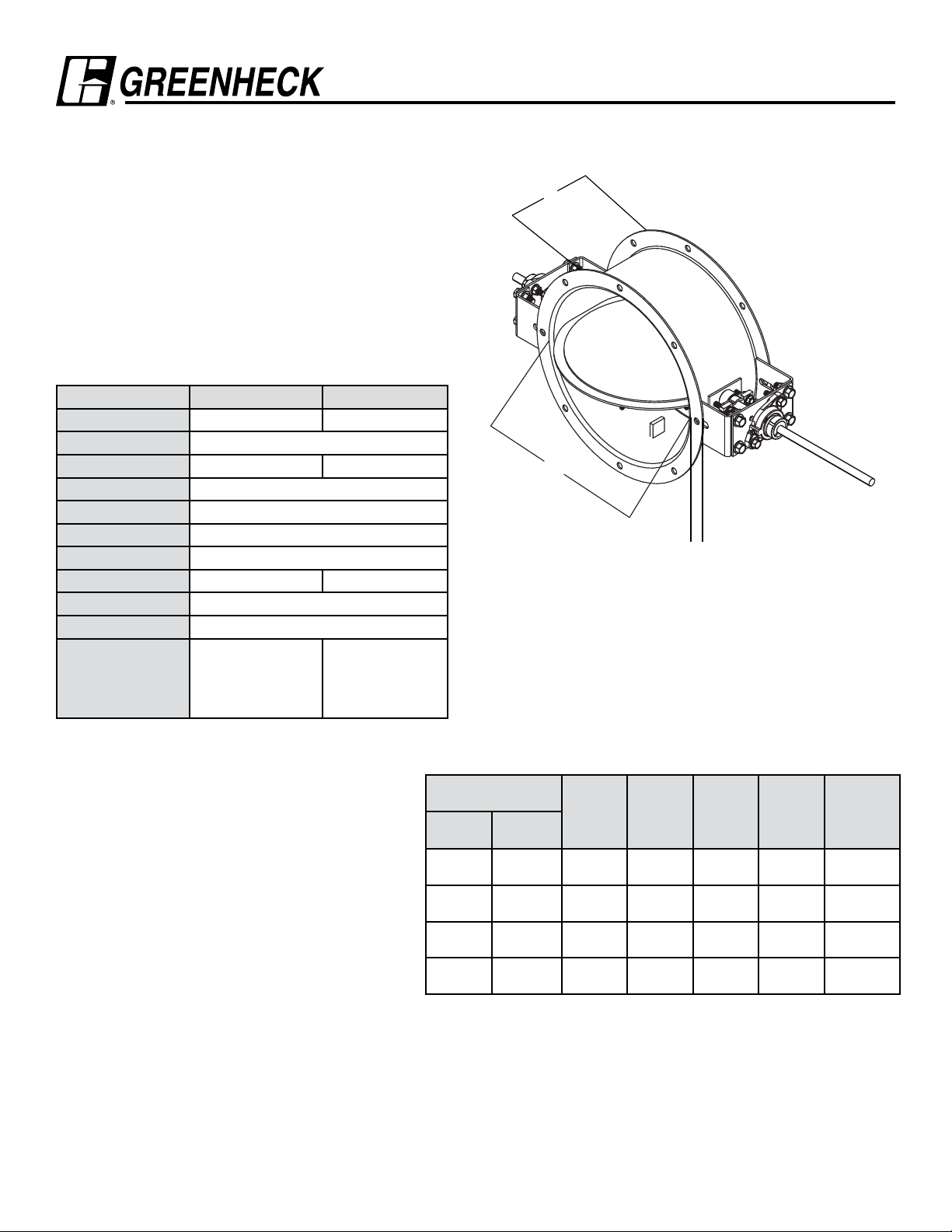
The HBTR-151 is an isolation damper designed for isolation
and decontamination applications. The damper has bubble
tight leakage performance per AMCA 500-D up to 10 in. wg
(2.5 kPa). The damper frame is flanged for easy mounting and
the blade seal is mechanically fastened to the blade.
Ratings
Leakage: Bubble tight per AMCA 500-D
Pressure: 10 in. wg (2.5 kPa) - differential pressure
Velocity: 3900 fpm (19.8 m/s)
Temperature: -40°F to 250°F (-40°C to 121°C)
Construction Standard Optional
Frame Material Painted Steel 304SS or 316SS
Frame Type Flanged Channel
Blade Material Painted Steel 304SS or 316SS
Blade Type Round, center pivoted, double skin
Blade Thickness 12 ga. (2.7mm)
Blade Seals Silicone rubber, mechanically fastened
Blade Stop full-open and full-close pin stops
Axle Material Painted Steel 303SS or 316SS
Axle Seal Double gland
Bearings Relubricable ball, outboard mounting
Epoxy,
Paint Finish Hi Pro Polyester
Industrial Epoxy,
Mill finish (304SS
or 316SS)
Model HBTR-151
Bubble Tight Isolation Damper
J
D*
F
* Actual Inside Dimension
Available Sizes:
Minimum Size: 5.906 in. (150mm) diameter
Maximum Size: 36 in. (914mm) diameter
Options:
• Mounting holes in flanges
• Actuators
• Limit Switches
• Special construction
Diameter (D)
Inches (mm)
Above Through
5.906
(150)
12
(305)
24
(610)
28
(711)
12
(305)
24
(610)
28
(711)
36
(914)
Installation instructions available at www.greenheck.com.
Frame
Depth J
Inches
(mm)
6
(152)
8
(203)
8
(203)
8
(203)
Frame &
Flange
gauge
(mm)
12
(2.7)
12
(2.7)
10
(3.5)
10
(3.5)
Flange
Width F
Inches
(mm)
1.5
(38)
1.5
(38)
2
(51)
2
(51)
Axle
Diameter
Inches
(mm)
0.5
(13)
0.75
(19)
0.75
(19)
1
(25)
Blade
Thickness
gauge
(mm)
12
(2.7)
12
(2.7)
12
(2.7)
12
(2.7)
Page 2
Performance Data HBTR-151
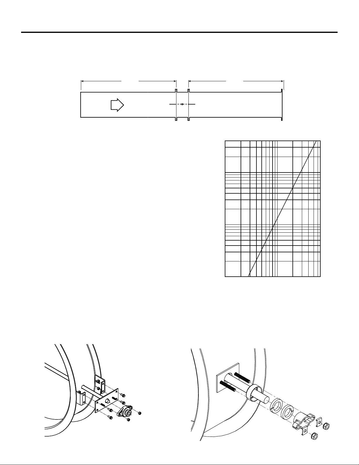
AMCA Test Figure 5.3
Figure 5.3 Illustrates a fully ducted damper. This configuration has low pressure drop because entrance and exit losses are
minimized by straight duct runs upstream and downstream of the damper.
AMCA Test Figure 5.3
4D 6D
Pressure Drop Data
This pressure drop data was conducted in accordance with
AMCA 500-D using Test Figure 5.3. All data has been corrected
to represent standard air at a density of 0.075 lb/ft3 (1.2kg/m3).
Actual pressure drop found in any HVAC system is a
combination of many factors. This pressure drop information
along with an analysis of other system influences should be
used to estimate actual pressure losses for a damper installed in
a given HVAC system.
Leakage
Every HBTR-151 is leakage tested at 10 in. wg (2.5 kPa) in
accordance with AMCA 500-D before it leaves the factory.
Greenheck does not ship a HBTR-151 unless it meets the
requirements of the standard.
0.40
0.30
0.20
0.10
0.09
0.08
0.07
0.06
0.05
0.04
0.03
0.02
0.010
0.009
0.008
0.007
0.006
Pressure Loss ( In. wg)
0.005
0.004
0.003
0.002
Pressure Drop
12 in. (305mm) dia. Damper
2 3 4 5 6 7 8 9 10
1
x 100
Ve locity (fpm)
2 3 4 5 6
x 1000
Bearing Detail
The ball bearings are mounted outboard for easy access.
The bearing comes with a grease fitting, allowing for easy
lubrication (axle seals included but not shown in bearing detail).
Axle Seal Detail
The double gland axle seal is mounted externally for easy
access and provides bubble tight performance.
Page 3

Frame Construction HBTR-151
Frame Construction Options
Bolt Holes:
Standard - Does not include bolt holes
Optional - Bolt holes in both flanges
Greenheck recommended bolt hole pattern is shown in the
table below. Customer must specify bolt holes that are parallel
to the axle centerline (P) or that straddle the axle centerline (S)
as shown in the diagrams below. Greenheck can also provide
bolt hole sizes and patterns other than those shown below.
Greenheck Recommended Bolt Hole Pattern
(Bolt Holes Parallel to Axle Centerline)
Diameter Inches
(mm)
Above Through
4
(102)
8.001
(203)
18.001
(457)
24.001
(610)
* Bolt Circle Diameter = Damper Diameter + Flange Height + 1/4 in. (6mm)
(203)
18
(457)
24
(610)
36
(914)
8
Number of
Holes
4
8
12
16
Mounting
Hole
Diameter
in. (mm) N
3/8
(9.5)
7/16
(11)
7/16
(11)
7/16
(11)
Bolt Circle
Diameter
L
* 90
* 45
* 30
* 22 1/2
Degrees
Between
Holes
On Centerline Straddle Centerline
Specifications
Industrial grade isolation dampers meeting the following
specifications shall be furnished and installed where shown on
plans and/or as described in schedules.
Dampers shall consist of round and flanged frame, full length
axle, double skin blade, solid silicone blade seal, double gland
axle seal and outboard ball bearings. Blade seal shall be
mechanically fastened to the blade and be field replaceable.
Blade shall be welded to the axle. Bearing shall be bolted to
outboard mounting plates and shall include a grease fitting for
relubrication. double gland stuffing box shall prevent leakage
around the axle.
Each damper shall be tested in accordance to AMCA Standard
500-D Bubble Tight Test at 10 in. wg (2.5 kPa) prior to shipping.
Damper manufacturer’s printed application and performance
data including pressure, and velocity limitations shall be
submitted for approval showing damper suitable for pressures
up to 10 in. wg (2.5 kPa), velocities up to 3900 fpm (19.8 m/s),
and temperatures to 250°F (121°C) maximum.
Frame gauges, blade gauges, and axle diameters shall be
equal to or exceed those of the model which is the basis of
design.
Basis of design is Greenheck model HBTR-151.
Copyright © 2014 Greenheck Corporation
HBTR-151 Rev. 6 October 2014
 Loading...