

Page 1
Document Number 469619
®
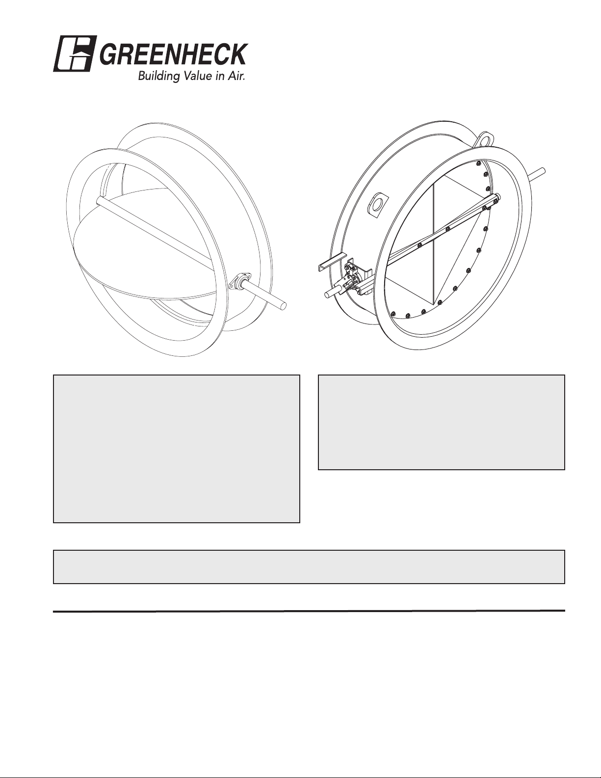
HBTR & HCDR SERIES
Installation, Operation, and Maintenance Instructions
RECEIVING AND HANDLING
Upon receiving dampers, check for both obvious
and hidden damage. If damage is found, record all
necessary information on the bill of lading and file
a claim with the final carrier. Check to be sure that
all parts of the shipment, including accessories, are
accounted for.
Dampers must be kept dry and clean. Indoor
storage and protection from dirt, dust and the
weather is highly recommended. Do not store at
temperatures in excess of 100°F (37ºC).
Due to continuing research, Greenheck reserves the right to change specifications without notice.
This manual is the property of the owner, and is required for future maintenance. Please leave it with the
owner when the job is complete.
Improper installation, adjustment, alteration,
service or maintenance can cause property
damage, injury or death. Read the installation,
operating, and maintenance instructions
thoroughly before installing or servicing this
equipment.
SAFETY WARNING:
Storage of Dampers Prior to Installation
The basic intent of a proper storage of heavy duty/industrial control and bubble tight damper is to prevent physical damage,
material corrosion, and deterioration of organic material.
1) Visually inspect the damper for damage. Store indoors, protected from sunlight, moisture and flooding. Protect dampers
from debris and dirt accumulation. Keep all conduit entry plugs and actuator access covers in place.
2) Dampers may be stacked and stored horizontally if wood or equivalent spacers are placed between flanges to protect
finish. Do NOT store with axles vertical. Place dampers on pallets or supports to allow air circulation. Do NOT store with
damper directly on concrete or ground.
3) The damper drive should be stored in a clean dry area. Do not stack drives on top of one another. Add desiccant
to electrical compartment if storage area temperature drops below 38°F. Damage due to moisture is not covered by
actuator warranty.
4) Consult manufacturer if storage time exceeds two years.
Page 2
Installation Guidelines - Failure to follow instructions will void all warranties
The basic intent of a proper installation is to secure the heavy duty/industrial control damper into the opening in such a
manner as to prevent distortion and disruption of damper operation. The following items will aid in completing the damper
installation in a timely and effective manner.
1) Dampers are supplied standard without mounting
holes. Drill or punch as required. If mounting holes are
supplied, use appropiate gasketing between mating
flanges. Closed cell sponge rubber, solid rubber,
maximum 60 durometer, or fiberglass drop warp tape
is recommended. For HBTR series, the seal between
the mating ductwork and the dampers flanges should
be tested to ensure a bubble tight seal is achieved.
If damper is replacing existing damper, clean mating
surfaces prior to installing new damper.
2) Allow minimum of half of the blade diameter, upstream
or downstream, in the duct for blade rotation.
3) Damper can be mounted vertically or horizontally with
axle horizontal. A split shaft collar must be added to
shaft to resist the blade weight if axle centerline is other
than horizontal.
4) Isolate damper from high vibratory loadings.
5) If any NEMA electrical enclosure is supplied, use
appropriate electrical connections so as to maintain the
NEMA rating.
Do’s
1) Use damper lifting lugs as provided.
2) Install all mounting bolts before tightening. Tighten in
even and staggered pattern to evenly compress flange
gasketing.
3) Mating flange must be flat and in the same plane.
4) Verify that damper does not strike mating ductwork or
internal ductwork reinforcing when blade is in the open
position.
5) Provide expansion joints upstream/downstream for
angled ductwork so damper is not subjected to thermal/
wind load forces off the centerline of damper.
Dont’s
1) Do not lift damper with chain/strap with blade propped
open and with chain/strap through frame as this could
damage blade seal.
2) Do not use actuator, linkage, or axles as lifting point.
3) Do not use prybar to match frame holes to mating
ductwork as frame can be warped or pulled out-ofround by excessive force.
4) Do not tighten mounting bolts by starting at one point
and “walking” around the damper as uneven flange
compression can result.
Electrical Guidelines
Electrical and/or pneumatic connections to damper actuators should be made in accordance with wiring and piping
diagrams developed in compliance with applicable codes, ordinances and regulations.
SAFETY CAUTION !
Verify power requirements before wiring
actuator. Greenheck is not responsible
for any damage to, or failure of the unit
caused by incorrect field wiring.
Electrical input may be needed for
this equipment. This work should be
performed by a qualified electrician.
SAFETY DANGER !
Damper Maintenance
Greenheck's dampers are designed to be trouble free and hassle free under normal operation. Dampers are to be installed
square and straight so as to prevent binding during operation. The following annual damper maintenance suggestions will
help to insure proper damper operation and increase the life expectancy of the damper.
Foreign Matter Over the course of time, dirt and grime may collect on damper surfaces. The damper surfaces
should be cleaned to prevent hindrance to airflow.
Moving Parts Make sure that parts such as linkage, bearings, blades, etc. that are intended to move freely,
can do so. Lubricating these components can prevent possible rusting and unnecessary friction
increase. Use only a molybdenum spray oil or similar graphite based oil on sleeve bearings as
regular lubricating oil will attract dirt.
Bearings. Synthetic, oil impregnated, carbon sleeve, and ball bearings (without grease fittings)
do not require lubrication. Ball bearings with grease fittings should be lubricated as follows:
Maximum Duct Temperature Lubricant Minimum Frequency
250° F 121° C
600° F 316° C
NLG1 Grade 2 lithium
12-hydrostearate grease
Hi temperature synthetic,
Mobillith SHC100 or equal
twice a year
four times a year
Page 3

Damper Maintenance cont....
Closure Remove foreign materials that may be interfering with blade closure or effective sealing of the
blades with each other or with the frame.
Blade Seals. Inspect annually. Replacement is recommended after 5 years to reduce the
potential of leakage on HBTR series. Damper serial number required when ordering replacement
seal.
Axle Seals. Inspect and adjust as necessary.
Operation While operating the damper through its full cycle, check to see that the blades open and close
properly. If there is a problem, check for loose linkage, especially at the actuator. Tighten the
linkage where required.
Actuator Cycle test actuator per manufacturer’s recommendations.
Damper Troubleshooting
The following is a cause and correction list for common concerns with the damper:
Problem Possible Cause Solution
No power to actuator Verify presence of correct power to actuator.
Actuator failed Power actuator independently of damper.
Damper does not move
Damper attempts to move
but, does not open fully
Actuator attempting to rotate in
wrong direction
Linkage/coupling failed Inspect coupling, keys, and connecting linkage for
No modulating signal Verify presence of modulating signal.
Obstruction in damper linkage
or inside duct
Actuator sizing incorrect
(excessive torque required)
Obstruction in damper linkage
or inside duct
Modulating control not going
full span
Actuator travel stops incorrectly
adjusted
Damper with jamb seals
installed with blades vertical
Check wiring. Run actuator independent of damper
if necessary.
failed or broken components. Replace as required.
Verify signal is compatible with actuator.
Verify if signal is driving actuator in the correct
direction.
Inspect for projecting mounting bolts, debris inside
damper and remove.
Verify that correct operating pressures, velocities,
and temperatures were given to manufacturer for
actuator sizing. Replace actuator if necessary.
Inspect for projecting mounting bolts, debris inside
damper and remove.
Verify control signal span from controller.
Some actuators are equipped with mechanical
stops to limit rotation. Adjust as necessary.
Consult factory, for modifications if vertical blade
orientation not specified on damper with seals.
High noise level
Very high velocity/flow Reduce flow through damper.
No seals on dampers Retrofit with blade seals.
Damper not closing fully Readjust actuator or drive linkage to fully close
damper.
Page 4

Damper Troubleshooting (continued)
Problem Possible Cause Solution
Damper not closing fully Readjust actuator or drive linkage to fully close
damper.
Excessive leakage
across damper
Excessive leakage through
damper frame
Damper not equipped with
blade and jamb seals
Blade edge seals failed Replace blade edge seals.
Stop angles not contacting
blade edges
Caulking failed Recaulk gaps with silicone sealant as required.
No axle seals specified Contact manufacturer for available modifications.
O-ring axle seals worn Replace o-rings as required.
Double gland packing not tight Tighten adjustment nuts on double gland stuffing
Double gland packing worn Replace packing as required.
Retrofit with blade seals.
Close damper. Loosen fasteners and adjust stop
angles so as to contact blade.
box.
Our Commitment
As a result of our commitment to continuous improvement, Greenheck reserves the right to
change specifications without notice.
Specific Greenheck product warranties are located on greenheck.com within the product
area tabs and in the Library under Warranties.
®
Phone: (715) 359-6171 • Fax: (715) 355-2399 • E-mail: gfcinfo@greenheck.com • Website: www.greenheck.com
469619• HBTR & HCDR Series Rev. 4, October 2014 Copyright 2014 © Greenheck Fan Corporation
 Loading...