

Page 1
Document number 469620
®
HB series
Installation, Operation, and Maintenance Instructions
This manual is the property of the owner, and is required for future maintenance. Please leave it with the
owner when the job is complete.
RECEIVING AND HANDLING
Upon receiving dampers, check for both obvious
and hidden damage. If damage is found, record all
necessary information on the bill of lading and file
a claim with the final carrier. Check to be sure that
all parts of the shipment, including accessories, are
accounted for.
Dampers must be kept dry and clean. Indoor
storage and protection from dirt, dust and the
weather is highly recommended. Do not store at
temperatures in excess of 100°F(37ºC).
Due to continuing research, Greenheck reserves the right to change specifications without notice.
Improper installation, adjustment, alteration,
service or maintenance can cause property
damage, injury or death. Read the installation,
operating, and maintenance instructions
thoroughly before installing or servicing this
equipment.
SAFETY WARNING:
Instructions
The following instructions should be followed when trying to adjust counterbalance weights on HB series
dampers. This is not intended to be used to modification for use as pressure relief damper.
Heavy Duty/Industrial backdraft damper are adjusted
for the specified flow direction at the factory. The
external counterbalance is adjusted for “easy operation”.
These instructions address adjustment of the blade
counterbalance for the following:
• Damper mounting orientation and/or flow direction has
changed in the field
• Damper requires excessive start-open pressure or does
not close
• Blade seal has been removed in the field
• Counterbalance settings have been erroneously
“adjusted” in the field
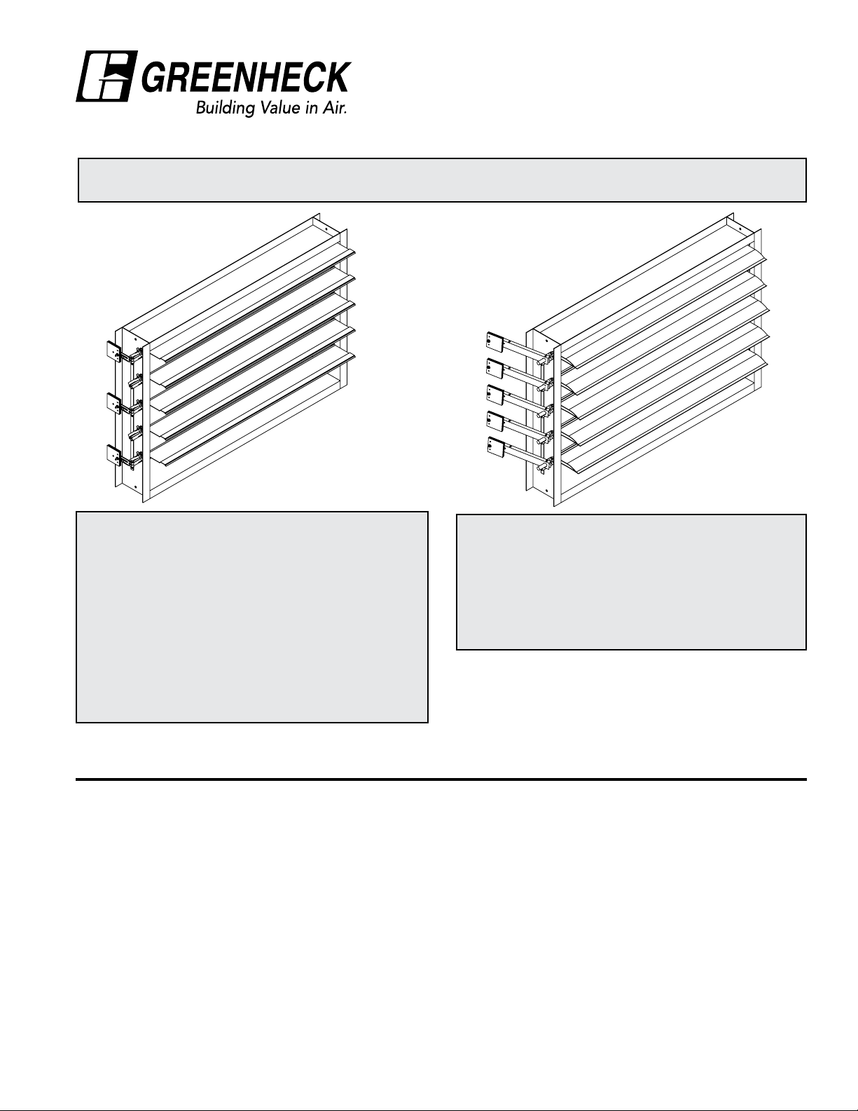
Single section wide dampers will have external blade
counterbalance on one (linkage) side of damper.
Dampers with two sections will have linkage on both
sides of damper assembly. Arms are usually mounted
on every other axle, starting at the bottom, until the
magnitude of the counterbalance requires arms on every
axle. The steel airfoil models HB-230 and HB-330 will
require more counterbalance weights than model HB-120
with single thickness blade or models HB-110 and HB240 with aluminum blades. The longer arms are angled
so they will nest when installed on every axle. Greenheck
policy is to distribute counterbalance evenly among
blades to minimize linkage loading and to improve blade
closure.
Page 2
Damper Maintenance
Greenheck's dampers are designed to be trouble free and hassle free under normal operation. Dampers are to be installed
square and straight so as to prevent binding during operation. The following annual damper maintenance suggestions will
help to insure proper damper operation and increase the life expectancy of the damper.
Foreign Matter Over the course of time, dirt and grime may collect on damper surfaces. The damper
surfaces should be cleaned to prevent hindrance to airflow.
Moving Parts Make sure that parts such as linkage, bearings, blades, etc. that are intended to move
freely, can do so.
Bearings. Plastic and pressfit ball bearings (without grease fittings) do not require
lubrication. Ball bearings with grease fittings should be lubricated as follows:
Maximum Duct
Temperature
°F °C Lubricant Minimum Frequency
250 121 NLGI Grade 2 lithium
12-hydrostearate grease
Closure Remove foreign materials that may be interfering with blade closure or effective sealing
of the blades with each other or with the frame. Inspect blade seals yearly and replace as
necessary.
Operation While operating the damper through its full cycle, check to see that the blades open and
close properly. If there is a problem, check for loose linkage.
Counterbalance Adjustment Instructions
1. Adjust FULL OPEN blade stop first. On most models,
a bolt with a spacer is used through the top linkage
clevis arm. Open and close damper to verify there
is no interference between axles and the nested
counterweight arm.
twice a year
2. Place damper in the installed mounting position and
flow direction.
3. Adjust blade counterbalance at full open position
first. Fan (flow) must not be operating. Rotate damper
blades open. the crankarms or counterweight arms
are generally 180° from the damper blade centerline.
On very small dampers with aluminum blades, the
crankarm may be inclined towards damper outlet, due
to the torque of the linkage. Adjust counterweight plate
center distance until blades will start to close from
full open position. Moving plate(s) out will increase
counterbalance. It may be necessary to add or delete
a plate. Counterweight plate quantity per arm should
not vary by more than one and the distance outward
from the axle centerline should not vary more than 1/2
inch among counterweight arms.
4. Close damper. Blades should close completely (you
can feel the blade edge seals make contact) without
slamming. NOTE: Counterweight arms are welded to
the axles as shipped. Arm adjustment will require weld
to be removed and to be rewelded after modification.
• If closing too hard, loosen arm fastener to the axle
and rotate top of arm towards upstream of air
entering side. Retighten fastener.
• If not closing, loosen the arm fastener to the axle and
rotate top of arm towards downstream or discharge.
Retighten fastener.
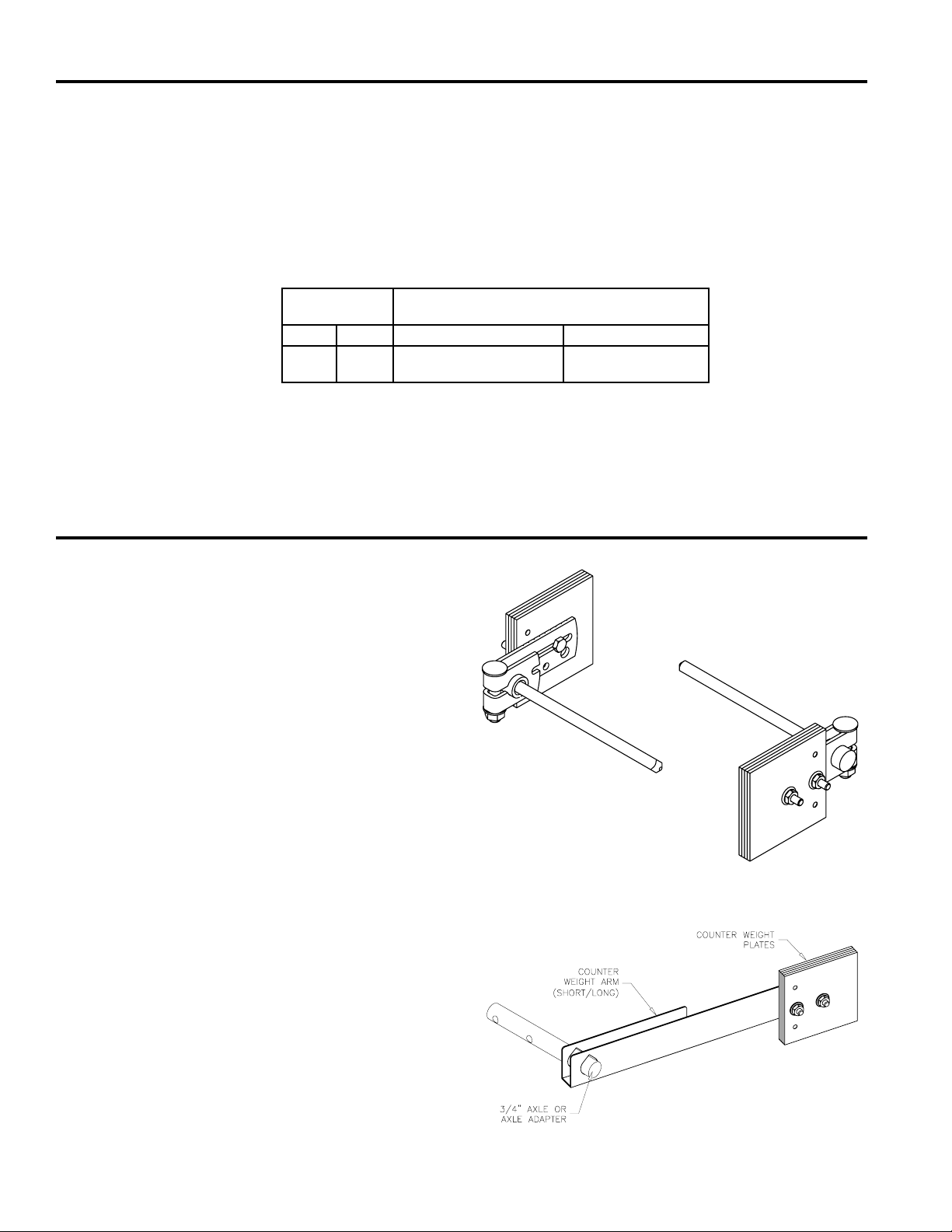
Counterbalance weight assembly
(square axle units)
Counterbalance arm assembly
(long & short arm)
Page 3

Counterbalance Adjustment Instructions cont...
5. Open damper and recheck full open operation.
Readjust per step 3 if necessary. Recheck full closed
position (step 4) as any modification at one position
has a slight impact on the other.
6. Tighten all counterweight and arm fasteners securely.
7. Test damper closure by opening damper blades and
releasing from 1/4, 1/2, 3/4 and full open position.
Damper should close from all positions without
assistance.
Standard Components
Component
Axle Adapter, 3/8” to ¾”
square OD
¾” Crankarm All 652982 687738
3/8”-16x2 Crankarm Bolt All 415882 415924
3/8”-16 Hex Nut for
Crankarm
Short Counterweight Arm
(8½ in. )
Long Counterweight Arm
(12½ in. )
3/8”-16 set screw for
short/long arm
3/8” -16 Weldnut/Hex nut
for short/long arm
Counterweight plate,
2½” x 3½”
Counterweight plate,
3½” x 3½”
¼”-20 Serrated Flange Nut All 415455 415575
¼”-20 x 3/4” Bolt All 415490 415573
¼”-20 x 1¼” bolt/
1½” bolt
Applicable
Model
HB-110, HB-120 370120 416343
All 415457 415799
All 657344 689404
All 657343 683951
All 415050 415763
All 415127 415799
All 653143 687636
All 653142 687635
All 415973 416103
Galvanized
Part Number
Stainless
Part Number
Our Commitment
As a result of our commitment to continuous improvement, Greenheck reserves the right to change
specications without notice.
Specic Greenheck product warranties are located on greenheck.com within the product area tabs and in
the Library under Warranties.
®
Phone: (715) 359-6171 • Fax: (715) 355-2399 • E-mail: gfcinfo@greenheck.com • Website: www.greenheck.com
469620• HB Series Rev. 2, October 2012 Copyright 2012 © Greenheck Fan Corporation
 Loading...