

Page 1
Document 479826
Model RSF and RSFP
®
Roof Supply Fan
Installation, Operation and Maintenance Manual
Please read and save these instructions for future reference. Read carefully before attempting to assemble,
install, operate or maintain the product described. Protect yourself and others by observing all safety
information. Failure to comply with instructions could result in personal injury and/or property damage!
WARNING!
To reduce the risk of fire, electric shock, or injury,
observe the following:
• Some units suitable for use with solid state speed
controls.
• When cutting or drilling into wall or ceiling, do not
damage electrical wiring or other hidden utilities.
• If connecting cables are found to be cut or
defective, switch off the power supply and call
a professional technician to replace the wires/
connection.
• Never place a switch where it can be reached
from a tub or shower.
• Ducted fans must always be vented to the
outdoors.
• These fans are not recommended for cooking
exhaust applications. They are designed primarily
for low temperature, clean air applications only.
• Fan is not intended for mounting in outside
windows or walls.
CAUTION!
• For general ventilating use only. Do not use to
exhaust hazardous or explosive materials and
vapors.
127, 208 and 220-240V/60Hz/1-phase
• Black wire is “Hot”
• White wire is “Hot/Neutral” if present
• Green wire or Green and Yellow stripe wire is
“Ground” if present
380 and 400V/60Hz/3-phase
• Black wires are “Hot”
• Green and Yellow stripe wire is “Ground” if present
Use a device for disconnection from the
supply, having a contact separation of at least
3 mm in double poles switch, which must be
incorporated in the fixed wiring in accordance
with the local electrical wiring rules.
For this fan, precautions must be taken to
avoid the back-flow of gases into the room
from the open-flue of gas or other fuelburning appliances.
This product must be properly and
reliably grounded.
Use this fan at the rated voltage and
frequency indicated on the name plate.
Do not allow water to contact electrical
parts such as motors or switches.
Do not switch this product on or off
in case of gas leakage; otherwise, the
electric spark may result in an explosion.
Do not spray or clean this product directly
with water or other liquid; otherwise, a short
circuit or an electrical shock may occur.
Do not disassemble the unit for
reconstruction.
Make sure that its power switch is set
to OFF before you touch this product;
otherwise, an eletrical shock may occur.
This fan must be installed by a qualified
technician.
This fan should be installed so that the
blades are more than 2.3 m above the
floor.
Routine maintenance is required every
year. Ensure that the fan is switched
off from the main supply power source
before removing the guard.
This appliance is not intended for the use
by persons (including children) with reduced
physical, sensory or mental capabilities,
or lack of experience and knowledge,
unless they have been given supervision or
instruction concerning use of the appliance
by a person responsible for their safety.
Children should be supervised to ensure
that they do not play with the appliance.
®
Roof Supply Fan 1
Page 2
Model RSF/RSFP
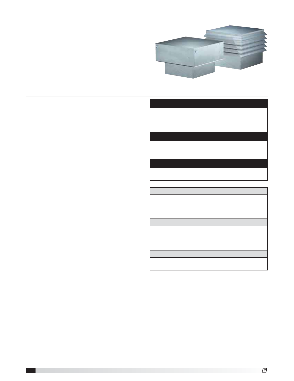
Model RSF/RSFP are belt drive supply fans. These
fans are specifically designed for filtered roof supply
applications. Performance capabilities range up to
14,300 cfm (24,296 m3/hr) and up to 2.0in.wg (498Pa)
of static pressure. RSF/RSFP fans are available in
six sizes ranging from a size 90 to a size 200. Each
fan shall bear a permanently affixed manufacturer’s
engraved metal nameplate containing the model
number and individual serial number.
General Safety Information
Only qualified personnel should install this fan.
Personnel should have a clear understanding of these
instructions and should be aware of general safety
precautions. Improper installation can result in electric
shock, possible injury due to coming in contact with
moving parts, as well as other potential hazards.
Other considerations may be required if seismic
activity is present. If more information is needed,
contact a licensed professional engineer before
moving forward.
1. Follow all local electrical and safety codes, as
well as the National Electrical Code (NEC) and the
National Fire Protection Agency (NFPA), where
applicable. Follow the Canadian Electric Code
(CEC) in Canada.
2. The rotation of the wheel is critical. It must be free
to rotate without striking or rubbing any stationary
objects.
3. Motor must be securely and adequately grounded.
4. Do not spin fan wheel faster than max cataloged
fan RPM. Adjustments to fan speed significantly
effects motor load. If the fan RPM is changed, the
motor current should be checked to make sure it is
not exceeding the motor nameplate amps.
5. Do not allow the power cable to kink or come in
contact with oil, grease, hot surfaces or chemicals.
Replace cord immediately if damaged.
6. Verify that the power source is compatible with the
equipment.
7. Never open access doors to a duct while the fan is
running.
DANGER
Always disconnect, lock and tag power source
before installing or servicing. Failure to disconnect
power source can result in fire, shock or serious
injury.
CAUTION
When servicing the fan, motor may be hot enough
to cause pain or injury. Allow motor to cool before
servicing.
CAUTION
Precaution should be taken in explosive
atmospheres.
DANGER
Pour écarter les risques d’incendie, de choc
électrique ou de blessure grave, veiller à toujours
débrancher, verrouiller et étiqueter la source de
courant avant l’installation ou l’entretien.
ATTENTION
Lors de toute intervention sur la soufflante, le moteur
peut être suffisamment chaud pour provoquer une
douleur voire une blessure. Laisser le moteur refroidir
avant toute maintenance.
ATTENTION
Faire preuve de précaution dans les atmosphères
explosives.
Roof Supply Fan2
®
Page 3

Receiving
Upon receiving the product, check to ensure all
items are accounted for by referencing the delivery
receipt or packing list. Inspect each crate or carton
for shipping damage before accepting delivery. Alert
the carrier of any damage detected. The customer will
make notification of damage (or shortage of items)
on the delivery receipt and all copies of the bill of
lading which is countersigned by the delivering carrier.
If damaged, immediately contact your Greenheck
Representative. Any physical damage to the unit after
acceptance is not the responsibility of Greenheck Fan
Corporation.
Unpacking
Verify that all required parts and the correct quantity
of each item have been received. If any items are
missing, report shortages to your local representative
to arrange for obtaining missing parts. Sometimes it
is not possible that all items for the unit be shipped
together due to availability of transportation and truck
space. Confirmation of shipment(s) must be limited to
only items on the bill of lading.
Handling
Fans are to be rigged and moved by the lifting
brackets provided or by the skid when a forklift is
used. Location of brackets varies by model and size.
Handle in such a manner as to keep from scratching
or chipping the finish. Damaged finish may reduce the
ability of the fan to resist corrosion.
Fans should never be lifted by the shaft, fan housing,
motor, belt guard, windband or accessories.
Storage
Fans are protected against damage during shipment. If
the unit cannot be installed and operated immediately,
precautions need to be taken to prevent deterioration
of the unit during storage. The user assumes
responsibility of the fan and accessories while in
storage. The manufacturer will not be responsible
for damage during storage. These suggestions are
provided solely as a convenience to the user.
Indoor - The ideal environment for the storage of
fans and accessories is indoors, above grade, in a
low humidity atmosphere which is sealed to prevent
the entry of blowing dust, rain or snow. Temperatures
should be evenly maintained between 30° to 110°F
(-1° to 43°C). Wide temperature swings may cause
condensation and “sweating” of metal parts. All
accessories must be stored indoors in a clean, dry
atmosphere.
Remove any accumulations of dirt, water, ice or snow
and wipe dry before moving to indoor storage. To
avoid “sweating” of metal parts allow cold parts to
reach room temperature. To dry parts and packages
use a portable electric heater to get rid of any moisture
buildup. Leave coverings loose to permit air circulation
and to allow for periodic inspection.
The unit should be stored at least 3½ in. (89 mm) off
the floor on wooden blocks covered with moisture
proof paper or polyethylene sheathing. Aisles between
parts and along all walls should be provided to permit
air circulation and space for inspection.
Outdoor - Fans designed for outdoor applications may
be stored outdoors, if absolutely necessary. Roads or
aisles for portable cranes and hauling equipment are
needed.
The fan should be placed on a level surface to prevent
water from leaking into the fan. The fan should be
elevated on an adequate number of wooden blocks so
that it is above water and snow levels and has enough
blocking to prevent it from settling into soft ground.
Locate parts far enough apart to permit air circulation,
sunlight and space for periodic inspection. To minimize
water accumulation, place all fan parts on blocking
supports so that rain water will run off.
Do not cover parts with plastic film or tarps as these
cause condensation of moisture from the air passing
through heating and cooling cycles.
Fan wheels should be blocked to prevent spinning
caused by strong winds.
Inspection & Maintenance During Storage
While in storage, inspect fans once per month. Keep a
record of inspection and maintenance performed.
If moisture or dirt accumulations are found on parts,
the source should be located and eliminated. At
each inspection, rotate the wheel by hand ten to
fifteen revolutions to distribute lubricant in motor and
bearings. If paint deterioration begins, consideration
should be given to touch-up or repainting. Fans with
special coatings may require special techniques for
touch-up or repair.
Machined parts coated with rust preventive should be
restored to good condition promptly if signs of rust
occur. Immediately remove the original rust preventive
coating with petroleum solvent and clean with lintfree cloths. Polish any remaining rust from surface
with crocus cloth or fine emery paper and oil. Do not
destroy the continuity of the surfaces. Thoroughly wipe
clean with Tectyl
®
506 (Ashland Inc.) or the equivalent.
For hard to reach internal surfaces or for occasional
use, consider using Tectyl
®
511M Rust Preventive,
WD-40® or the equivalent.
Removing from Storage
As fans are removed from storage to be installed
in their final location, they should be protected and
maintained in a similar fashion until the fan equipment
goes into operation.
®
Roof Supply Fan 3
Page 4
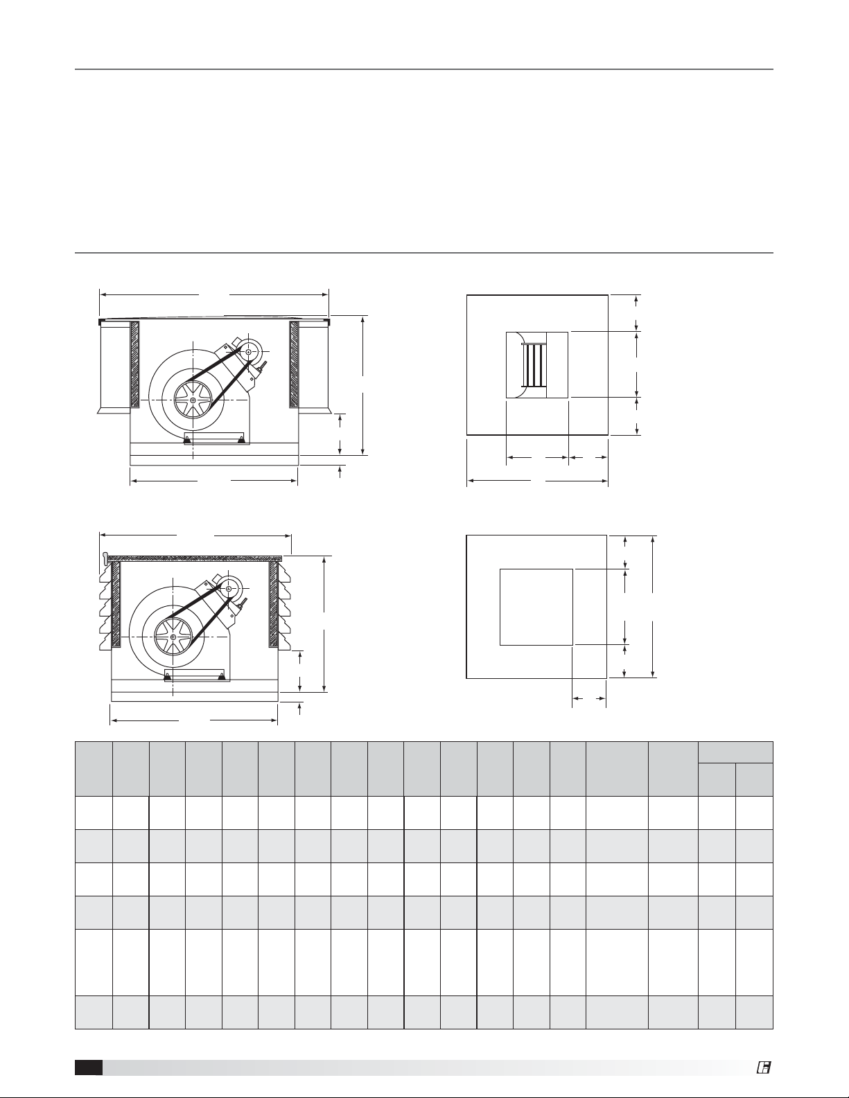
Table of Contents
General Safety Information . . . . . . . . . . . . .2
Receiving, Unpacking, Handling, Storage . . . . . .3
Inspection and Maintenance During Storage . . . .3
Dimensional Data . . . . . . . . . . . . . . . . . .4
Lifting. . . . . . . . . . . . . . . . . . . . . . . . .5
Installation . . . . . . . . . . . . . . . . . . . . . .5
Mounting for Severe Duty Installation . . . . . . . .6
Dimensional Data
RSF
B SQ.
C
D
21/2 in.
SQ.
A
Electrical Connection . . . . . . . . . . . . . . . .7
Pre-Starting Checks . . . . . . . . . . . . . . . . .7
Routine Maintenance . . . . . . . . . . . . . . . .8
Parts List . . . . . . . . . . . . . . . . . . . . . . .9
Maintenance Log. . . . . . . . . . . . . . . . . . 10
Our Commitment. . . . . . . . . . . . . . . . . . 10
Base of Unit
J
F
J
G
A
H
RSFP
BL SQ.
CL
D
21/2 in.
A
SQ.
Fan
SizeA SQ.B SQ.
26 351⁄8 317⁄8 231⁄4 253⁄8 101⁄4 121⁄4 103⁄4 75⁄8 67⁄8 241⁄2 121⁄4 61⁄8 (4) 12x20
90
(660) (892) (810) (591) (645) (260) (311) (273) (194) (175) (662) (311) (156) (305x508) (66) (57)
30 411⁄8 357⁄8 231⁄4 253⁄8 101⁄4 135⁄8 117⁄8 91⁄16 83⁄16 281⁄2 141⁄4 71⁄8 (4) 12x25
100
(762) (1045) (911) (591) (645) (260) (346) (302) (230) (208) (724) (362) (181) (305x635) (78.5) (66)
34 471⁄8 397⁄8 271⁄4 293⁄8 101⁄4 161⁄8 137⁄8 101⁄16 815⁄16 321⁄2 181⁄4 71⁄8 (4) 16x25
120
(864) (1197) (1013) (692) (746) (260) (410) (352) (256) (227) (826) (464) (181) (406x635) (102) (82)
40 531⁄8 457⁄8 311⁄4 333⁄8 101⁄4 191⁄8 161⁄2 111⁄4 107⁄16 381⁄2 201⁄4 91⁄8 (8) 16x20
150
(1016) (1349) (1165) (794) (848) (260) (486) (419) (286) (265) (978) (514) (232) (406x508) (152) (113)
46 611⁄8 5 17⁄8 341⁄4 353⁄8 121⁄4 221⁄2 191⁄2 101⁄8 113⁄4 441⁄2 261⁄4 91⁄8
180
(1168) (1153) (1318) (870) (899) (311) (571) (495) (257) (298) (1130) (667) (232) (4) 20x20 (181) (129)
52 731⁄8 583⁄16 391⁄4 403⁄8 121⁄4 231⁄4 251⁄4 133⁄8 143⁄8 501⁄2 301⁄4 101⁄8 (8) 20x25
200
(1321) (1857) (1478) (997) (1026) (311) (591) (641) (340) (365) (1283) (768) (257) (508x635) (281) (196)
BL
CCLDFGHJ
SQ.
All dimensions are in inches (millimeters). Pounds (kg).
Optional Duct Adapter
K
SQ.L SQ.
M
M
Nominal
Filter
(4) 16x20
(406x508)
(508x508)
M
L
SQ.KSQ.
M
Louver
Tiers
RSFP
3
3
4
5
5
6
Weights
RSF RSFP
145 126
173 146
225 180
336 250
400 285
620 431
Roof Supply Fan4
®
Page 5
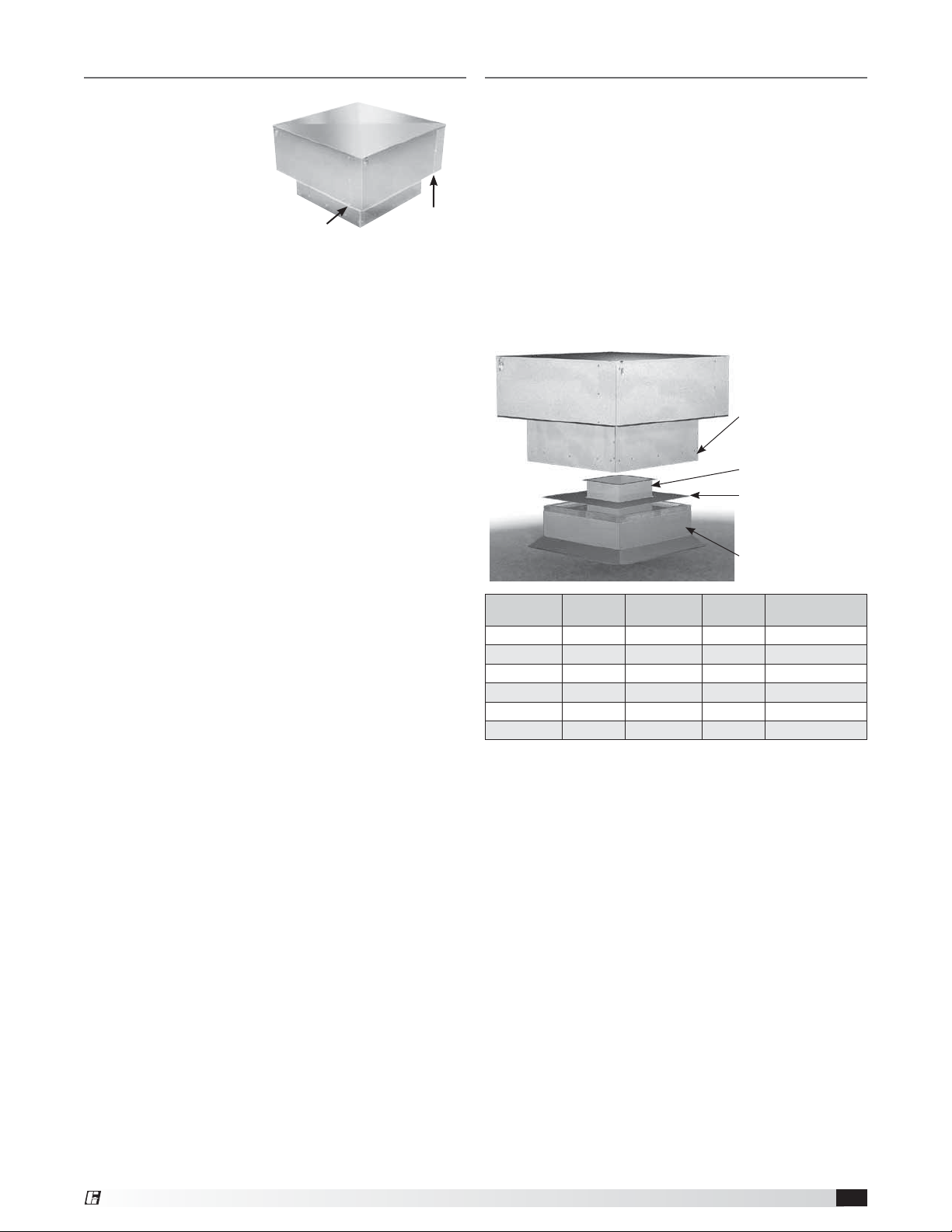
Lifting
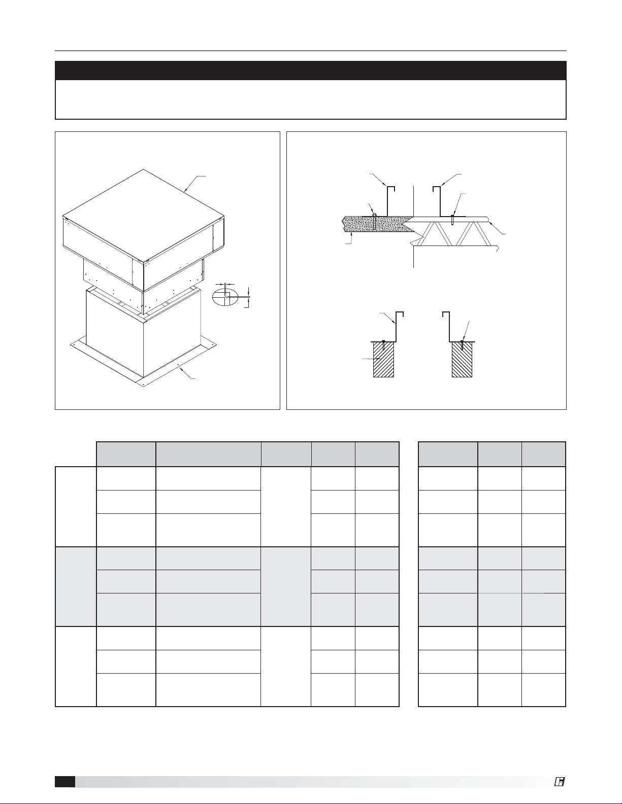
Installation
Lifting the RSF and
Figure 1
RSFP fans must be
done with care to
avoid damaging the
housing. For model
RSF, attach four
lifting devices under
the outer housing,
Lift Here
Lift Here
each device beneath
the vertical row of fasteners as depicted in Figure 1.
Lifting devices should be a minimum of 3 inches wide
to avoid damaging the sheet metal housing.
Do not lift Model RSF near the center of the outer
housing.
For Model RSFP attach a minimum of four lifting
devices under an exterior louver panel, each device
near the corner of the louvered housing.
Move the fan to its intended location and fasten it
securely through mounting holes provided in the
fan base. Shims may be necessary depending
upon thickness of the roofing material. For ducted
applications, an optional duct adapter (if provided)
is attached and holds the ductwork in place prior to
installing the unit. The following diagram shows a
typical installation with prefab roof curb and ductwork.
Access to the motor compartment is made by
releasing four latches which secure the cover. The
cover should be placed in an area where wind will not
blow it off the roof.
Typical Installation
Prepunched mounting
holes and 21⁄2 in. skirt
to aid in installation.
Ductwork (by others)
Duct adapter (optional)
allows ductwork to
be completed prior to
setting unit on curb.
Roof curb
Fan Size Curb Size*
RSF/RSFP-90 24
RSF/RSFP-100 28
RSF/RSFP-120 32
RSF/RSFP-150 38
RSF/RSFP-180 44
RSF/RSFP-200 50
All dimensions are in inches (millimeters).
* Recommended curb size shown is outside curb dimension without roofing
and flashing.
Note: In cases where extreme snow depths may be encountered, extended
base may be required to raise unit or condensation pans may be required in
ductwork.
1
1
1
1
1
⁄2 (1130) 29 (737) 26 (660) 26 x 26 (737x737)
1
⁄2 (1283) 33 (838) 30 (762) 30 x 30 (838x838)
Recommended
Roof Opening
⁄2 (662) 15 (381) 12 (305) 12 x 12 (305x305)
⁄2 (724) 17 (432) 14 (356) 14 x 14 (356x356)
⁄2 (826) 21 (533) 18 (457) 18 x 18 (457x457)
⁄2 (978) 23 (584) 20 (508) 20 x 20 (508x508)
Duct Size ID Nominal Damper Size
®
Roof Supply Fan 5
Page 6
Mounting for Severe Duty Installations
IMPORTANT
Installation instructions for seismic ratings are only recommendations. Final design must be determined by
Structural Engineer of Record (SEOR) including requirements for curb construction, mounting of unit to curb
and mounting of curb to structure.
Fan to Curb: Three (3) fasteners are required
per side on all sides. Must be equally spaced.
RSF Series
1.25
1.25
Curb Corner
Anchor Detail
Roof Curb
Model SD, SDP, GPF or Equivalent
18 ga. Min.
24 in. (610 mm) Tall Max.
Welded Steel Construction
Curb to Deck: Fasteners need to be located on two
opposite ends of the curb.
Roof Curb Roof Curb
3/8 in. (10 mm) S.S. Hilti Kwik Bolt
Three Expansion Anchors
Min. 2-1/2 in. (64 mm) Engagement
2000 Min. PSI
Concrete
Concrete
Deck Anchoring
Roof Curb
Wood Timber
Min. 4 in. (102 mm)
Nominal Thickness
Min. G = 0.42
G = specific gravity
of lumber
Deck Anchoring
Timber Anchoring
1/4 in. - 14 Self-Drilling Screw
Min. 1/2 in. (13 mm) of Threads Through
Steel
3/8 in. (10 mm) Lag Bolt (Zinc Plated)
Min. 3 in. (76 mm) Thread Engagement
High Wind Ratings Seismic Ratings
Roof Truss
1/8 in. (3 mm) Thick
or 12 ga. Min.
Fan Size Curb Cap Size
Concrete
Steel
Timber
90, 100, 120
150
180, 200
90, 100, 120
150
180, 200
90, 100, 120
150
180, 200
(660x660 to 864x864 mm)
(1168x1168 to 1321x1321
(660x660 to 864x864 mm)
(1168x1168 to 1321x1321
(660x660 to 864x864 mm)
(1168x1168 to 1321x1321
All dimensions are in inches
26x26 to 34x34
40x40
(1016x1016 mm)
46x46 to 52x52
mm)
26x26 to 34x34
40x40
(1016x1016 mm)
46x46 to 52x52
mm)
26x26 to 34x34
40x40
(1016x1016 mm)
46x46 to 52x52
mm)
(millimeters)
.
Self-Drilling
Screw Size
3/8-inch
1/4” - 14
3/8-inch
Fasteners
Per Side
Total
Fasteners
Fan Size
Fasteners
per side
3 6 90, 100, 120 3 6
4 8 150 4 8
5 10 180, 200 5 10
3 6 90, 100, 200 3 6
4 8 150 4 8
5 10 180, 200 5 10
3 6 90, 100, 120 3 6
4 8 150 4 8
5 10 180, 200 5 10
Total
Fasteners
Roof Supply Fan6
®
Page 7

Electrical Connection
Pre-Starting Checks
The electrical supply must be compatible with the fan
motor with regard to voltage, phase and amperage
capacity. Moreover, the electrical supply line must
be properly fused and conform to local and national
electrical codes.
Electrical lead-in wires should be routed through the
pre-punched hole in the optional duct adapter (if
provided) and the punched hole in the bottom of the
fan housing. Electrical wires must be located so as not
to rub on moving components. The electrical supply
line is connected to an optional safety disconnect
switch (if provided) or wired directly to the motor.
Wiring should be secured inside the fan to prevent
interference with the drive components. All wiring must
conform to local and national codes.
DANGER
Disconnect and secure to the “off” position all
electrical power to the fan prior to inspection
or servicing. Failure to comply with this safety
precaution could result in serious injury or death.
DANGER
Pour écarter les risques de blessure grave ou
de mort, débrancher et verrouiller l’alimentation
électrique en position « Arrêt » avant tout contrôle ou
entretien.
Units with motor and drives shipped separate, refer to
Motor Mounting Instructions included in hardware bag.
Check all fasteners and set screws for tightness.
Rotate the fan wheel by hand to assure it turns freely
and is centered between the inlets. Check pulleys and
belts for proper alignment to avoid premature belt
wear, noise, vibration and power loss. Motor and fan
pulleys must be parallel and in alignment; Figure 2.
CORRECT WRONG WRONG WRONG
Figure 2
Adjustable motor pulley is set at the factory for the fan
RPM specified. Fan speed can be increased by closing
or decreased by opening the adjustable motor pulley.
Two groove variable pitch pulleys must be adjusted an
equal number of turns open. Any increase in fan speed
results in an increase in horsepower required for the
motor. Motor amperage should always be checked
and compared to nameplate rating when changing fan
speed.
Direction of fan wheel rotation is critical. A fan wheel
rotating in the wrong direction
will result in reduced airflow,
a
t
t
i
o
o
n
motor overloading and possible
R
burnout. Check wheel rotation
by momentarily turning the fan
on.
Rotation should be in the same
direction as airflow at the outlet.
See housing and wheel example
in Figure 3.
Figure 3
Airflow
IMPORTANT
RSF/RSFP fans should be operated only when
attached to the completed system. Without
proper static pressure loading, the motor may be
overloaded and burnout may occur.
®
Roof Supply Fan 7
Page 8

Routine Maintenance
DANGER
Disconnect and secure to the “off” position all
electrical power to the fan prior to inspection
or servicing. Failure to comply with this safety
precaution could result in serious injury or death.
DANGER
Pour écarter les risques de blessure grave ou
de mort, débrancher et verrouiller l’alimentation
électrique en position « Arrêt » avant tout contrôle ou
entretien.
To preserve the reliability and performance designed
into the fan, regularly scheduled maintenance
should be performed. Items to be checked at each
maintenance interval are filters, belts, bearings,
fasteners, lubrication and removal of dust and dirt.
Filters - One-inch washable aluminum mesh filters
are standard on model RSF and RSFP fans. Optional
two-inch filters may be supplied on some fans. Filters
should be cleaned on a regular basis for optimum
efficiency.
To remove the filters, first remove the fan cover by
releasing the four latches. Place the cover in an area
where wind will not blow it off the roof. The filters can
be lifted out and washed in a mild detergent solution.
If desired, an adhesive spray available at most filter
distributors can be applied to increase filter efficiency.
Belts - Belt tension should be checked two times
during the first 24 hours of operation and during each
scheduled maintenance thereafter. Premature belt
failures are frequently caused by improper belt tension,
either too tight or loose. The proper belt tension for
operating a V-belt is the lowest tension at which the
belt will not slip at peak load conditions. For initial
tensioning, belt deflection should be 1/64 inch for
each inch of belt span, determined by using moderate
thumb pressure half
way between pulley
centers. For example,
the belt deflection
should be 1/2 inch
if the belt span is
32inches; Figure 4.
Figure 4
Belt tension can be adjusted by loosening the motor
plate hinge bolts and adjusting the jack screws as
required. RSF/RSFP units are supplied with either a
painted steel motor bracket or a galvanized motor
plate for larger motor frames. To adjust belt tension on
units equipped with the painted steel motor bracket,
simply adjust the single jack screw.
For units equipped with a galvanized motor plate,
both jack screws must be adjusted equally. Check
pulley and belt alignment after adjusting belt tension;
Figure2.
Belt Span
Deflection =
Belt Span
64
Lubrication - Fan bearings on models RSF and
RSFP are permanently lubricated. Motor bearings
equipped with grease fittings should be lubricated in
accordance with instructions on the motor nameplate.
Motors without grease fittings are lubricated for life.
Cleaning - Motors and fan wheels require periodic
cleaning to remove dust and dirt which may
accumulate. Motor cleaning should be limited to the
exterior surface only. Removing dust and dirt from the
motor housing assists in motor cooling and prolongs
motor life. Motors should never be sprayed with
steam, water or solvents.
Fan wheels which are left to accumulate dust and dirt
will have poor air performance, loss of efficiency and
possible damaging vibration due to an unbalanced
condition.
Periodic cleaning is a good investment in preserving
the reliability and performance designed into the fan.
Roof Supply Fan8
®
Page 9

Parts List
Each fan bears a manufacturer’s nameplate with model number and serial number embossed. This information
will assist the local Greenheck representative and the factory in providing service and replacement parts. Before
taking any corrective action, make certain unit is not capable of operation during repairs.
CAUTION
A fan manufactured with an explosion resistant
motor does not certify the entire unit to be explosion
proof. Refer to ULListing Mark for the fans approved
usage.
Filters
Shaft Pulley
Belt
Vibration Isolators (4)
CAUTION
La présence d’un moteur antidéflagrant sur un
ventilateur ne garantit pas que tout l’appareil est
antidéflagrant. Pour connaître les emplois autorisés
de l’appareil, voir son marquage de conformité UL.
Blower Unit
*Motor Plate
Motor
Motor Pulley
Blower Mounting Angle
*Galvanized motor plate shown. Painted steel motor bracket used on units with smaller motor frame sizes.
®
Roof Supply Fan 9
Page 10

Maintenance Log
Date _______________ Time _________________AM/PM
Notes: __________________________________________
________________________________________________
________________________________________________
________________________________________________
Date _______________ Time _________________AM/PM
Notes: __________________________________________
________________________________________________
________________________________________________
________________________________________________
Date _______________ Time _________________AM/PM
Notes: __________________________________________
________________________________________________
________________________________________________
________________________________________________
Date _______________ Time _________________AM/PM
Notes: __________________________________________
________________________________________________
________________________________________________
________________________________________________
Date _______________ Time _________________AM/PM
Notes: __________________________________________
________________________________________________
________________________________________________
________________________________________________
Date _______________ Time _________________AM/PM
Notes: __________________________________________
________________________________________________
________________________________________________
________________________________________________
Date _______________ Time _________________AM/PM
Notes: __________________________________________
________________________________________________
________________________________________________
________________________________________________
Date _______________ Time _________________AM/PM
Notes: __________________________________________
________________________________________________
________________________________________________
________________________________________________
Our Commitment
As a result of our commitment to continuous improvement, Greenheck reserves the right to change specifications
without notice.
Specific Greenheck product warranties are located on greenheck.com within the product area tabs and in the
Library under Warranties.
Greenheck’s Centrifugal Roof Supply Fans catalog provides
additional information describing the equipment, fan
performance, available accessories, and specification data.
AMCA Publication 410-96, Safety Practices for Users and
Installers of Industrial and Commercial Fans, provides
additional safety information. This publication can be
obtained from AMCA International, Inc. at www.amca.org.
®
Phone: 715.359.6171 • Fax: 715.355.2399 • Parts: 800.355.5354 • E-mail: gfcinfo@greenheck.com • Website: www.greenheck.com
479826 • RSF/RSFP, Rev. 3, May 2015 Copyright 2015 © Greenheck Fan Corporation10
Page 11

ΔϧΎϳλϟϝΟγ
҄ҖһӪܜٙҖҪҖҙӂ _____________ҠӞӷӦҕ ______________ ҰӽҵҖҟӦҕ
ٙ
_____________________________________ ܐҝҖӏҪڔӪ
___________________________________________
___________________________________________
___________________________________________
҄ҖһӪܜٙҖҪҖҙӂ _____________ҠӞӷӦҕ ______________ ҰӽҵҖҟӦҕ
ٙ
_____________________________________ ܐҝҖӏҪڔӪ
___________________________________________
___________________________________________
___________________________________________
҄ҖһӪܜٙҖҪҖҙӂ _____________ҠӞӷӦҕ ______________ ҰӽҵҖҟӦҕ
ٙ
_____________________________________ ܐҝҖӏҪڔӪ
___________________________________________
___________________________________________
___________________________________________
҄ҖһӪܜٙҖҪҖҙӂ _____________ҠӞӷӦҕ ______________ ҰӽҵҖҟӦҕ
ٙ
_____________________________________ ܐҝҖӏҪڔӪ
___________________________________________
___________________________________________
___________________________________________
҄ҖһӪܜٙҖҪҖҙӂ _____________ҠӞӷӦҕ ______________ ҰӽҵҖҟӦҕ
ٙ
_____________________________________ ܐҝҖӏҪڔӪ
___________________________________________
___________________________________________
___________________________________________
҄ҖһӪܜٙҖҪҖҙӂ _____________ҠӞӷӦҕ ______________ ҰӽҵҖҟӦҕ
ٙ
_____________________________________ ܐҝҖӏҪڔӪ
___________________________________________
___________________________________________
___________________________________________
҄ҖһӪܜٙҖҪҖҙӂ _____________ҠӞӷӦҕ ______________ ҰӽҵҖҟӦҕ
ٙ
_____________________________________ ܐҝҖӏҪڔӪ
___________________________________________
___________________________________________
___________________________________________
҄ҖһӪܜٙҖҪҖҙӂ _____________ҠӞӷӦҕ ______________ ҰӽҵҖҟӦҕ
ٙ
_____________________________________ ܐҝҖӏҪڔӪ
___________________________________________
___________________________________________
___________________________________________
ӠҙһӪҵҖӓҾҏӭӶұҝҖӛӂҕӷڛҕӨӽҲҙҞڒҖӴӟҫҘGreenheckӐӛҟҫҞ܃ҶӽӷӋҟӦҕҜӧӂҕӷӫҘӬҒҕҲӦҕҖӯӪҕҸҟӦړҜҧӾҟӮ
ҜҙҟӣڛҕڒҖٙӇӽ҉ӶҨҟӯڛҕҜӟӋӯڛҚӽӷҙҟӦҕҝҖӪڔӒӥڔҮӰӪӤӦҳӶ܃greenheck.comӿӮӶٸӣӦڙҕӔӞӷڛҕڝӒGreenheckҝҖҧҟӯڛқұҲҫӪҝҖӮҖӫӆҲҦӷҞ
ӿӾӯӚӶۧӪҲүҟһڛҖҘҜӂҖүӦҕҜӪڔһӦҕҝҖҺҵҖӫӪҬӆӷӽ܃410ܞˀ6 ӬӞҵAMCAҵӷҿӯӪ
ӭҖӣӪڙҖҘҜӪڔһӦҖҘӠӧӓҟҞҜӾӚҖӆҏҝҖӪӷӧӓӪҖٙӇӽ҉ӶҜӾӒҖӯӃӦҕӶҜӽҵҖҧҟӦҕҩӶҕҶӫӧӦҚӾӢٸӦҕ
www.amca.orgӔӞӷڛҕڝӒҜӾڛҖӓӦҕ AMCAҜӢٿӰӪҵӷҿӯڛҕڝӒӥӷӃҫӦҕ
ҝҖӪӷӧӓӪGreenheckӰӪӼҸӢҶڛҕұҶӋӦҕҝҕҳӜӟһӦҕұҕҲӪҏҩӶҕҶӪҥӷӦҖҟӢҶӚӷӽ
ҝҖӛӂҕӷڛҕҝҖӮҖӾҘӶқҶӚӷҟڛҕҝҖӟҫӧڛҕӶҜҪӶҶڛҕ҄ҕұ҉ӶҸӾӴҧҟӧӦҖٙӛӂӶӿӋӓҞҜӾӚҖӆҏ
ҖӯӪҕҸҟӦҕ
ҝҖӮҖӫӇӦҕӨӛҺ҉
®
www.greenheck.comܐӿӮӶٸӣӦڙҕӔӞӷڛҕƷgfcinfo@greenheck.comܐӿӮӶٸӣӦڙҕҲӽٷӦҕƷ8003ʼʼʼ3ʼ4ܐҵҖӾӗӦҕӔӋӞƷʾ1ʼ3ʼʼ23ˀˀܐҼӢҖӚƷʾ1ʼ3ʼˀ61ʾ1ܐӜҞҖӳ
Greenheck Fan CorporationҜӢڀӦʛ2015ڀӯӦҕӶӔҙӋӦҕӝӷӟҪ 2015ӷӽҖӪ܃3ҜӓҦҕҶڛҕ܃RSF/RSFPƷ479826
10
Page 12

҄ҕҸҦڗҕҜӫҒҖӞ
GreenheckҜӢٿۥңӫӪӶӔӯӃڛҕҝҖӪӷӧӓڛҕӱҴӳҲӒҖһҞәӷҺӶۥһӧһҟӦҕӬӞҶӦҕӶҷҕҶӋӦҕӬӞҵӔӪҜӓӯӃڛҕҜӴҧӦҕӬҺҕҖӴӾӧӒҵӷӛҫӪӔӯӂҜҪӷӦӨӫҫҞҜҪӶҶӪӨӢ
ҬӾӧӃҟӦҕ҄ҖӯҢ҉ӨӫӓӦҕڝӒқҵұҖӞۦӖҜӾӯӓڛҕқҲҪӷӦҕӨӓҦҕ܃ҜӾҫӾҫӃҞҝҕ҄ҕҶҦҏӼ҉ҳҖүҞҕӨҙӞҵҖӾӗӦҕӔӋӞӶҜӪҲүӦҕۦӚӷҞڒ
CAUTION
La ÆróÉence ºƠËn moteËr antiºófÂagrant ÉËr Ën
ÌentiÂateËr ne garantit ÆaÉ ÇËe toËt ÂƠaÆÆarei eÉt
antiºófÂagrantoËr connaČtre ÂeÉ emÆÂoiÉ aËtoriÉóÉ
ºe ÂƠaÆÆareiÂƑÌoir Éon marÇËage ºe conformitó UL
ҶҞڔӛӦҕ
ӭҕҵӶҲӦҕұӷӫӒқҶӣҘ
ۦһӦҕ
(4) ҷҕҸҟӳړҕӥҷҕӷӒ
ӵӾҙӯҞ
қҲҪӷӦҕҜӪӶҖӟӪӭҖӫӆӿӯӓҞړҵҖҧӛӮڔӦөӶҖӟӪӡҶҫӫҘҜӓӯӃӫӦҕҜҪӶҶӫӦҕ
өҕҲүҟҺڔӦҜҙһӯӦҖҘULӄӾҮҶҟӦҕҜӪڔӒӻӦҏӔҦҵҕҵҖҧӛӮڔӦӨӪҖӣӦҖҘ
ҩӶҕҶӫӧӦҲӫҟӓӫӦҕ
ӔӚҲӦҕҜҪӶҶӪқҲҪӶ
ӡҶҫӫӦҕҜҪӷӦdž
ӡҶҫӫӦҕ
ӡҶҫӫӦҕқҶӣҘ
ӔӚҲӦҕҜҪӶҶӪҠӾҙңҞҜӽӶҕҷ
Ҷӗӂ҉ӡҶҫӪҵҖӊҏөҖҧҪ҉ӔӪҝҕҲҪӷӦҕڒҜӪҲүҟһڛҕҜӾӧӋڛҕҜӽҳړӷӛӦҕӡҶҫڛҕҼӽұҕӷӞөҲүҟһҞӰӛӧҧڛҕӡҶҫڛҕҩӷӦӅҶӒӬҟӽdž
9
ӜӟһӦҕ ұҕҲӪҏ ҜҪӶҶӪ
®
Page 13

ҜӾӯӾҞӶҶӦҕҜӮҖӾӃӦҕ
қҵӷӃҘҖӴҟӾӽҸҞӬҟӽRSFӶRSFҝڔӽұӷڛҕڒӨӪҖҫӫӧӦҜҙһӯӦҖҘܞҠӾӽҸҟӦҕ
ٙҖӟӚӶҖӴҟӾӽҸҞҚҧӽӬӾҫҿҟӧӦҥҖҟҫҞҝҖҙӾӢٸҘқұӶҸڛҕӡҶҫڛҕҝڔӫҫӪҜӫҒҕұ
ӼӷҟҫҞړӿҟӦҕҝҖӢҶҫڛҕӬӾҫҿҞӬҟӽӡҶҫڛҕӔӯӂҜҪӷӦڝӒқұӷҦӷڛҕҝҖӫӾӧӓҟӧӦ
ӥҕӷӊӸҶҮ҉қҶӪҖӴӫӾҫҿҞڜҏҥҖҟҫҞړҤӾҫҘӬӾҫҿҞڜҏҥҖҟҫҞҝҖҙӾӢҶҞڝӒ
қҖӾҫӦҕ
ҜҘҶҞڗҕҜӦҕҷڙӼҵӶұӜӾӏӯҞҜҪӶҶڛҕҝڔҧӒӶҝҖӢҶҫڛҕҚӧӋҟҞܞ
ӜӾӏӯҟӦҕ
ڝӒқچҟӟӪӡҶҫڛҕҜӚҖӏӮӭӷӣҞӭ҉ӿӗҙӯӽӬӢҕٸҞӭ҉ӰӣӫӽӿҟӦҕқҵҕҴӟӦҕӶ
ҲӽٷҞڒӡҶҫڛҕҠӾҙӪӰӪҵҖҙӗӦҕӶҜҘҶҞڗҕҜӦҕҷҏҲӒҖһҞӌӟӚҜӾҦҵҖүӦҕҬӋҺڗҕ
ӨӾӦҖҫڛҕӶ҉҄ҖڛҕӶ҉ҵҖүҙӦҖҘҝҖӢҶҫڛҕҽҵٙҖӪҖӫҞҶӏҫӽӱҶӫӒқұҖӽҷӶӡҶҫڛҕ
҄ҕұ҉ҝҕҳҖӴӾӧӒҵҖҙӗӦҕӶҗҕٸӦҕӬӢҕٸӽӻҟҪӡٸҞӿҟӦҕҜҪӶҶڛҕҝڔҧӒӭӷӣҟҺ
ҜӦҖҫӦҕҚҙһҘҜӧӫҟҫڛҕқҶӪҲڛҕҝҕҷҕҸҟӳړҕӶҖӴҞ҄ҖӛӢӜӓӆӰӒٙڔӇӚ҄ٽӿҒҕӷӳ
ҜӮҸҟڛҕۦӖ
ڒӬӫӃڛҕ҄ҕұڗҕӶҜӾӞӷҢӷڛҕڝӒӍҖӛҫӦҕڒٙҕҲӾҦٙҕҵҖӫңҟҺҕӼҵӶҲӦҕӜӾӏӯҟӦҕҲӓӽӶ
ҜҪӶҶڛҕ
ҶӋҮ
ӔӆӶӿӚҜӾҒҖҘҶӴӣӦҕҜӞҖӋӦҕҵұҖӃӪӨӢӔӆӶӰӪӠӟҫҟӦҕӶӨӃӛҘӬӞ
ҝҖӾӧӫӒ҄ҕҶҦҏӨҙӞҜҪӶҶӫӦҕӻӦҏҜӞҖӋӦҕӨӂӷҞӿҟӦҕͲӨӾӗҿҟӦҕәҖӟӽҏͲ
ӠӧӓҟӫӦҕӉҖӾҟҪړҕҕҴӴҘөҕҸҟӦړҕөҲӒӼұҎӽӭ҉ӰӣӫӽҜӮҖӾӃӦҕӶ҉ӄҫӛӦҕ
қҖӚӷӦҕӻӦҏӶ҉қҶӾӋҮҝҖҘҖӂҏҡӶҲҪӻӦҏҜӪڔһӦҖҘ
DANGER
oËr ócarter ÂeÉ riÉÇËeÉ ºe ¸ÂeÉÉËre graÌe oË ºe
mortƑºó¸rancher et ÌerroËiÂÂer ÂƠaÂimentation
óÂectriÇËe en ÆoÉitionܔArrôtܕaÌant toËt contrĥÂe oË
entretien
ҜӫӏҟӯڛҕҜӮҖӾӃӦҖҘөҖӾӟӦҕҚҧӽ܃қӷҦҶڛҕڒӬӫӃڛҕ҄ҕұڗҕӶҜӾӞӷҢӷڛҕڝӒӍҖӛҫӧӦ
ҜӪҸҪړҕӶҝҖҫҾҶڛҕӿӳҜӮҖӾӂҜӧҪҶӪӨӢڒҖӴӯӪӠӟҫҟӦҕҚҧӽӿҟӦҕڅҖӯӓӦҕ
ҵҖҙӗӦҕӶҜҘҶҞړҕҜӦҕҷҏӶӬӾҫҿҟӦҕұҕӷӪӶҝҖҟҙңڛҕӶӨӪҖҫڛҕӶ
ӰӪҜӒӷӯӃڛҕҜӂӷҘҲҪҕӶҹҖӟӪҜӾӣҙҿӦҕҝҖҫҾҶڛҕӿҞҋҞ
ӶRSFӨӽұӷڛҕӰӪҩӶҕҶڛҕڒҜӾҺҖӾӞқҵӷӃҘӨһӗӧӦҜӧҘҖӟӦҕӶөӷӾӯӪӷӦڗҕ
ҩӶҕҶڛҕӈӓҘڒҜӽҵҖӾҟҮҕҜӂӷҘ2ҹҖӟӪҝҖҫҾҶӪҲӽӶҸҞӰӣӫӽRSF
ҜӾӦҖңڛҕ҄ҖӛӣӦҕӨҦ҉ӰӪӼӷӯҺҹҖҺ҉ڝӒҝҖҫҾҶڛҕӜӾӏӯҞҚҧӽ
ӠӦҕҸӪӔҘҵڗҕӝҖҟӒҏӥڔҮӰӪҜҪӶҶڛҕ҄ҖӋӖӥҕҷҐҘړӶ҉ӬӞ܃ҝҖҫҾҶڛҕҜӦҕҷڙ
ӔӚҵӰӣӫӽӜӟһӦҕӰӒٙҕҲӾӓҘҖӴӓӚұڝӒҩҖӽҶӦҕӨӫӓҞӰӦҜӟӋӯӪڒ҄ҖӋӗӦҕӔӆ
ҳҕҳҵөҕҲүҟҺҕӰӣӫӽ܃ҜҙӖҶӦҕҲӯӒӥҲҟӓӪӜӏӯӪӥӷӧҫӪڒҖӴӧһӖӶҝҖҫҾҶڛҕ
ҬҾҶڛҕқ҄ҖӛӢқұҖӽҸӦӰҫҾҶڛҕҝҖӓӽҷӷҞӬӏӓӪڒӠӂړ
ӰӪҜӒҖҺ24ӨӢۧҞҶӪөҕҸҫӦҕҲҾӥҲӓӪӰӪӠӟҫҟӦҕҚҧӽ
ӭҕӶڗҕӰӒҶӣҙڛҕӜӧҟӦҕӬҧӯӽӤӦҳҲӓҘқҵҶӟӪҜӮҖӾӂҜӾӧӫӒӥڔҮӶӨӾӗҿҟӦҕ
ӰӒҲҒҕҷӨӣҿҘқұӶҲҿӪҠӮҖӢҕҳҏٙ҄ҕӷҺҵӷӾһӧӦҬӾҫӃӦҕۦӖҲҿӦҕӰӒҵӷӾһӧӦ
ڝӒҵӷӾһӦҕӨӾӗҿҟӦҚҺҖӯڛҕҲҿӦҕӸӷҟһӪӶҲҫӦҕӰӒҲҒҕҷӨӣҿҘҜҙҒҖҺӶ҉ҲҫӦҕ
әӶҶӎڒҵӷӾһӦҕӱҲӯӒӠӦҸӯҞړӼҴӦҕӻӮұڗҕҲҿӦҕұҕҲӒҏӷӳVәҶҪӨӣҾ
өҕҸҫӦҕәҕҶҫӮҕӭӷӣӽӭ҉Қҧӽ܃ӿҒҲҙڛҕҲҿӦҕқұҖӒڙқӶҵҴӦҕҝړҖҪڒҜӦӷӫҫӦҕ
өҕҸҪӸҲӪӨӣӦҜӂӷҘ1ܜ64
ﲑﺴﻟا داﺪﺘﻣا
ӌӗӆөҕҲүҟҺҕӥڔҮӰӪұҲҫӽӶ
ӜӃҟӯӪڒӥҲҟӓڛҕӔҙӂړҕ
ڝӓӚқҶӣҙӦҕҸӢҕҶӪۧҘҜӚҖһڛҕ
ӭӷӣӽӭ҉Қҧӽ܃ӥҖңڛҕӨӾҙҺ
ҕҳҏқӷӃҘ1ܜ2өҕҸҫӦҕәҕҶҫӮҕ
܃ҜӂӷҘ32өҕҸҫӦҕӸҲӪӭҖӢ
4ӨӣҿӦҕ
ﲑﺴﻟا داﺪﺘﻣا
64
= فاﺮﺤﻧﻻا
ӨӽҲӓҞӶӡҶҫڛҕҩӷӦӠӾӧӓҞۦӪҖһӪӤӚӥڔҮӰӪөҕҸҫӦҕҲҾӨӽҲӓҞӰӣӫӽ
ҜғӾӳڝӒRSFƭRSFҝҕҲҪӶҲӽҵӷҞӬҟӽҗӷӧӋڛҕӷҫӯӦҕڝӒӌҘҶӦҕۦӪҖһӪ
ٷӢ҉ҝҕҵҖӊҏӨҦ҉ӰӪҜӯӛӧҧӪӡҶҫӪҩҕӷӦ҉Ӷ҉ҜӾӧӋӪҜӽҳړӷӚӡҶҫӪҼӽұҕӷӞ
ҜӽҳړӷӚӡҶҫӪҼӽұҕӷӟҘқұӶҸڛҕҝҕҲҪӷӦҕڒөҕҸҫӦҕҲҾӨӽҲӓҟӦӡҶҫӫӧӦ
ӼұҶӛӦҕӿҙӦӷӧӦҕҵҖӫһڛҕӨӽҲӓҟҘҜӊҖһҙҘӬӞ܃ҜӮӷӳҲӪ
ӰӽҵҖһڛҕڔӢӨӽҲӓҞۧӓҟӽ܃ҜӯӛӧҧӪӡҶҫӪҩҕӷӦҋҘқұӶҸڛҕҝҕҲҪӷӧӦҜҙһӯӦҖҘ
ҲҾӨӽҲӓҞҲӓҘөҕҸҫӦҕӶқҶӣҙӦҕқҕҳҖҫӪӰӪӠӟҫҞҜӽӶҖһҟӪқҵӷӃҘۧӾҙӦӷӧӦҕ
ܞҝҖҫҾҶڛҕ
ܞҜӪҸҪړҕ
4ӨӣҿӦҕ
2ӨӣҿӦҕ܃өҕҸҫӦҕ
®
ӜӟһӦҕ ұҕҲӪҏ ҜҪӶҶӪ
8
Page 14

ӨӾӗҿҟӦҕӨҙӞҖӪҝҖӂӷҫӚ
ӿӮӶٸӣӦڙҕӨӾӂӷҟӦҕ
ҶӋҮ
ӔӆӶӿӚҜӾҒҖҘҶӴӣӦҕҜӞҖӋӦҕҵұҖӃӪӨӢӔӆӶӰӪӠӟҫҟӦҕӶӨӃӛҘӬӞ
ҝҖӾӧӫӒ҄ҕҶҦҏӨҙӞҜҪӶҶӫӦҕӻӦҏҜӞҖӋӦҕӨӂӷҞӿҟӦҕͲӨӾӗҿҟӦҕәҖӟӽҏͲ
ӠӧӓҟӫӦҕӉҖӾҟҪړҕҕҴӴҘөҕҸҟӦړҕөҲӒӼұҎӽӭ҉ӰӣӫӽҜӮҖӾӃӦҕӶ҉ӄҫӛӦҕ
қҖӚӷӦҕӻӦҏӶ҉қҶӾӋҮҝҖҘҖӂҏҡӶҲҪӻӦҏҜӪڔһӦҖҘ
DANGER
oËr ócarter ÂeÉ riÉÇËeÉ ºe ¸ÂeÉÉËre graÌe oË ºe
mortƑºó¸rancher et ÌerroËiÂÂer ÂƠaÂimentation
óÂectriÇËe en ÆoÉitionܔArrôtܕaÌant toËt contrĥÂe oË
entretien
ҝҖӫӾӧӓҞڜҏӔҦҵҕ܃ӨӃӛӯӪӨӣҿҘӔӚҲӦҕҝҕҲҪӶӶӡҶҫڛҕҝҕҳҝҕҲҪӷӦҕӰҫҿҞ
қҲҪӷӦҕқӷҙӒڒқұӷҦӷڛҕӡҶҫڛҕҠӾҙңҞ
ҜҪӶҶڛҕҜӧҧӒҵұ҉ҜӫӣҫӪҖӴӮ҉ӰӪҲӢҋҟӧӦӨӽҲӓҟӦҕӨӾӪҕӷӂӶҝҖҟҙңڛҕӨӢӄҫӛҞ
ҝҕҶӣҙӦҕқҕҳҖҫӪӰӪӠӟҫҞӨҮҕҲڛҕۧҘҖӳҸӢҶӫҞӶҜӽҶҫҘҖӴҞҵҕҲҟҺҕӭҖӫӇӦҲӾӦҖҘ
ӭӷӣҞӭ҉ҚҧӽҜӞҖӋӦҕҲӟӚӶҷҕҸҟӳړҕӶ҄ҖӆӷӇӦҕӶۦһӦҕӨӢ҇ҞҚӯҧҟӦҵӷӾһӦҕӶ
2ӨӣҿӦҕҶӏӮҕ܃ӼҳҖҫӪӨӣҿҘӶҜӽҷҕӷӪӡҶҫڛҕӶҜҪӶҶڛҕҝҕҶӣҘ
ҬӾҫӂ ҋӋҮ ҋӋҮ ҋӋҮ
ӠӧӓҟӽҖӫӾӚҜҪӶҶڛҕӡҶҫӪӔӪٙҖӟӚҕӷҟӪҜӞҖӋӦҖҘұҕҲӪڙҕҵҲӃӪӭӷӣӽӭ҉Қҧӽ
ұҕҲӪҏӌҮۦӚӷҞҚҧӽӤӦҳӰӒٙڔӇӚӿҘҶӴӣӦҕҵҖӾҟӦҕҜӓҺӶҜӧҪҶڛҕӶҜӾҟӦӷӛӦҖҘ
ҜӾӧҫڛҕҜӾӮӶٸӣӦڙҕۧӮҕӷӟӦҕӔӪӤӦҳӠӚҕӷҟӽӭ҉ҚҧӽҖӫӢҬӾҫӂӨӣҿҘӿҘҶӴӢ
ҜӾӯӊӷӦҕӶ
ҔӽҖӴӪڒٙҖӟҙһӪҩӷҟӛڛҕҚӟңӦҕٷӒҜӧӂӷڛҕҜӾҘҶӴӣӦҕӡڔҺڗҕӵӾҦӷҞҚҧӽ
ۧӓҟӽҜҪӶҶڛҕҠӾҙӪӨӛҺ҉ҩӷҟӛڛҕҚӟңӦҕӶܖٙҕҶӚӷҟӪӭҖӢҕҳҏܗӼҵҖӾҟҮړҕҗӷҙӮڗҕ
ӬҟӽҜӢҶҫҟڛҕҝҖӮӷӣڛҕӔӪӡҖӣҟҪҕҖӴӦҡҲҫӽړҜӾҘҶӴӣӦҕӡڔҺڗҕӭҖӣӪҲӽҲҫҞ
ӬҟӽӶ҉ܖөҲӞҕҳҏܗӼҵҖӾҟҮړҕҜӪڔһӦҕӨӃӚҩҖҟӛӫҘӿҘҶӴӣӦҕұҕҲӪڙҕӌҮӨӾӂӷҞ
ӡҶҫڛҕڜҏқٿҖҙӪӵӧӾӂӷҞ
ҝҖӮӷӣӪӔӪӨҮҕҲҟӦҕӔӯӪӨҦ҉ӰӪҜҪӶҶڛҕӨҮҕұӡڔҺڗҕҠӾҙңҞӬҟӽӭ҉ҚҧӽӶ
ҜӾӯӊӷӦҕӶҜӾӧҫڛҕۧӮҕӷӟӦҕӔӪӡڔҺڗҕӔӾӫҦӠӛҟҞӭ҉ҚҧӽӔӚҲӦҕқҲҪӶ
2ӨӣҿӦҕ
ӭҕҵӶҲӦҕҝҕҶӪұҲӒڝӒӥӷӃҫӧӦӔӯӃڛҕӔӆӶӠӚӶӡҶҫڛҕқҶӣҘۧӾӓҞӬҟӽ
ҬҟӚӶ҉ӝڔӖҏӠӽҶӊӰӒҖӴӇӛҮӶ҉ҜҪӶҶڛҕҜӒٹӔӚҵӰӣӫӽҜӟӾӞҲӦҕڒқұҲҫڛҕ
ۦӗҟӪӸӷҟһӫҘӭҖҞҷҸҫӪӭҖҞҶӣҘӌҙӇҞӭ҉ҚҧӽӨӽҲӓҟӧӦҜӧҘҖӟӦҕқҶӣҙӦҕӸҶҧӪ
құҖӽҷڜҏӼұҎҞҜҪӶҶڛҕҜӒٹڒқұҖӽҷӼ҉ҬҟӛӦҕҝҕҶӪұҲӒҼӛӮӔӪҖӟӚҕӷҟҟӦ
ҜӦӷӫҪҜӽۦҙӪ҉ӰӪӠӟҫҟӦҕٙҖӫҒҕұҚҧӽӡҶҫڛҕӰӪҜҘӷӧӋڛҕҜӾӮҖӃҫӦҕқҵҲӟӦҕڒ
ҜҪӶҶڛҕҜӒٹۦӾӗҞҲӯӒӔӯӃӦҕҜҪӷӦӜӾӯӃҟҘҖӴӮҵҖӞӶӡҶҫڛҕ
Ҳ
ҟ
Ӷ
Ӧ
ӽ
ҕ
Ҷ
ӼұҎҞҜҺҖһҪҜӦҋһӪқҵҖӋӦҕӭҕҵӶұӱҖҧҞҕӭҏ
ڜҏҔӊҖүӦҕӱҖҧҞړҕڒҵӶҲҞӿҟӦҕҜҪӶҶڛҕҜӧҧӒ
ӡҶҫڛҕڝӒӉҶӛڛҕӨӫҫӦҕӶӿҒҕӷӴӦҕӠӚҲҟӦҕӈӛҮ
ӰӪҜӧҧӓӦҕӭҕҵӶұӰӪӠҫҞӝҶҫӧӦҜӾӦҖӫҟҪҕӶ
қҸӾҦӶқٸӛӦҜӞҖӋӦҖҘқҲҪӷӦҕӨӾӂӷҞӥڔҮ
ҲӯӒӭҕҵӶҲӦҕӱҖҧҞҕҼӛӮڒҖٙҙӦҖӖӭҕҵӶҲӦҕӭӷӣӽӶ
ڒқҵҖӋӦҕӶҠӾҙڛҕҜӧңӪ҉ڝӒӔӧӊҕҥҶүڛҕ
3ӨӣҿӦҕ
҄ҕӷӴӦҕӠӚҲҞ
3ӨӣҿӦҕ
өҖӳ
ӭӶұӨӫҟӣӫӦҕөҖӏӯӦҖҘҖӴӞҖҫӦҏҕҳҏړҏRSFƭRSFҩӶҕҶӪӨӾӗҿҞҶӏҫӽ
ҡҲҫӽҲӞӶӨӫҫӦҕӉҶӚӰӪӡҶҫӫӦҕӿӮҖӓӽҲӟӚ܃ҚҺҖӯӪӿӣӾҞҖҟҺӌӗӆӨӫҪ
ӝҕҶҟҪҕ
7
ӜӟһӦҕ ұҕҲӪҏ ҜҪӶҶӪ
®
Page 15

ҜӞҖҿӦҕҜӪҲүӦҕҝҖҙӾӢҶҞڒҚӾӢٸӦҕ
өҖӳ
ӤӦҳӿӚҖӫҘܖSEORܗҝڔҧһӧӦҝҕ҄ҖҿӮڙҕҹҲӯӴӪӥڔҮӰӪӿҒҖӴӯӦҕӬӾӫӃҟӦҕҶӽҶӟҞӬҟӽӭ҉ҚҧӽҝҖӾӂӷҞұҶҧӪړҏӿӳҖӪҜӾӦҕҸӦҸӦҕҝҖӫӾӾӟҟӦҕҚӾӢҶҞҝҖӫӾӧӓҞ
ӨӣӾӴӦҕӻӧӒҸҦҖҫӦҕҚӾӢҶҞӶҸҦҖҫӦҕӻӧӒқҲҪӷӦҕҚӾӢҶҞӶҸҦҖҫӦҕ҄ҖҿӮҏҝҖҙӧӋҟӪ
ӰӒҝҖҟҙңӪܖ3ܗҜҢڔҢұӷҦӶөҸӧӽܐҸҦҖҫӦҕڝӒҜҪӶҶڛҕҚӾӢҶҞ
ҜӽӶҖһҟӪҖӴӯӾҘҜӚҖһڛҕӭӷӣҞӭ҉ҚҧӽҚӮҕӷҧӦҕӨӢڒҚӮҖҦӨӢ
RSF ҜһӧһӦҕ
1.25
1.25
ҸҦҖҫӦҕҜӽӶҕҷ
ҠӾҙңҟӦҕӔӆӷӪӨӾӂҖӛҞ
ӵӦұҖӓӽҖӪӶ҉ GPF Ӷ҉ SDP Ӷ҉ SD Өӽұӷڛҕ
ڈӞ҉ҲҫҘ (ӬӧӪ 610) ҜӂӷҘ 24 ӥӷӋӦҕ
ӜӟһӦҕҸҦҖҪ
ҜӟӾӞҲӦҕڒӭӷӦҖӖ 18
өӷҫӧӪӼҳړӷӚӨӣӾӳ
ۧҟӧҘҖӟҟڛҕۧҟӽҖӴӯӦҕڝӒҝҖҟҙңڛҕҲҦҕӷҟҞӭ҉ҚҧӽܐҜӃӯӪڝӒҸҦҖҫӦҕҚӾӢҶҞ
ӜӟһӦҕҸҦҖҪӜӟһӦҕҸҦҖҪ
ӤӽӷӢӿҟӧӾӳҵҖӫһӪ S.S. (ӬӧӪ 10) ҜӂӷҘ 3/8
(ӬӧӪ 64) ӻӮұ҉ҲҫҘҜӂӷҘ 2-1/2 ӌҘҵ
Өӊҵ 2000 ҜӮҖҺҶҮ
ӻӮұ҉ҲҫҘҜӂӷҘӨӣӦ
ӔӾҺӷҞҝҖҟҙңӪҜҢڔҢ
ҜӾӮҖҺҶҮҜӃӯӫҘҠӾҙңҞ ҜӽҳړӷӚҜӃӯӫҘҠӾҙңҞ
ӜӟһӦҕҸҦҖҪ
(ӬӧӪ 102) ӻӮұ҉ҲҫҘҜӂӷҘ 4
0.42 =ӿӒӷӯӦҕӭҷӷӧӦӻӮұڗҕҲҫӦҕ
ҹӻӃӳڟҙܒҞӃҳӫӪܒҵҶүڟҙ ܒԃӖӻӳӪҙܒӱһӻӪҙ = G
҄ҖӯҙӦҕҚҿҮ
ӿӫҺړҕӤӫһӦҕ
ҚҿүӦҕҠӾҙңҞ
ҜӂӷҘ 1/2 ӻӮұҕҲҫҘ -14 ҜӂӷҘ 1/4 ҚӟңӦҕӿҞҕҳҵҖӫһӪ
Ӷ҉ (ӬӧӪ 3) ҜӂӷҘ 1/8 ӤӫҺ
ҜӂӷҘ 3/8 ҹҖӟӪҜؿҺҕҲҺҹ҉ҶҘӿҙӦӷӦҵҖӫһӪ
ӥӷҮҲӦҖӾӮҲӦҕҜӚҖһڛҕӶ (ӤӮҸӦҖҘۥӋӪ) (ӬӧӪ 10)
(ӬӧӪ 76 ) ҜӂӷҘ 3 ӭҖӯҺڗҕ
ҸҦҖҫӧӦ
ҜӾҙӦӷӧӦҕҖӯӯһڛҕӰӪ (ӬӧӪ 13)
ӜӟһӦҕӭӷӦҖӫҦ
ӻӮұ҉ҲҫҘӭӷӦҖӖ 12
ۤҖӫҦڙҕ
ҝҖҟҙңڛҕ
ҝҖҟҙңڛҕұҲӒ
ҚӮҖҦӨӢڒ
ҜҪӶҶڛҕҹҖӟӪ
ۤҖӫҦҏ
ҝҖҟҙңڛҕ
ҝҖҟҙңڛҕұҲӒ
ҚӮҖҦӨӢڒ
36120܃100܃ˀ036
481ʼ048
ʼ10200܃180ʼ10
36200܃100܃ˀ036
481ʼ048
ʼ10200܃180ʼ10
36120܃100܃ˀ036
481ʼ048
ʼ10200܃180ʼ10
ҜӾҞҕҳӿӖҕٷӦҕҹҖӟӪ
ҠӾҙңҟӦҕӶҚӟңӦҕ
ҜӂӷҘ3ܜ8ҹҖӟӪ
14ܞҜӂӷҘ1ܜ4
ҜӂӷҘ3ܜ8ҹҖӟӪ
34ܣ34ڜҏ26ܣ26
ܖӬӧӪ864ܣ864ڜҏ660ܣ660ܗ
40ܣ40
ܖӬӧӪ1016ܣ1016ܗ
ʼ2ܣʼ2ڜҏ46ܣ46
ܖӬӧӪ1321ܣ1321ڜҏ1168ܣ1168ܗ
34ܣ34ڜҏ26ܣ26
ܖӬӧӪ864ܣ864ڜҏ660ܣ660ܗ
40ܣ40
ܖӬӧӪ1016ܣ1016ܗ
ʼ2ܣʼ2ڜҏ46ܣ46
ܖӬӧӪ1321ܣ1321ڜҏ1168ܣ1168ܗ
34ܣ34ڜҏ26ܣ26
ܖӬӧӪ864ܣ864ڜҏ660ܣ660ܗ
40ܣ40
ܖӬӧӪ1016ܣ1016ܗ
ʼ2ܣʼ2ڜҏ46ܣ46
ܖӬӧӪ1321ܣ1321ڜҏ1168ܣ1168ܗ
қҲӽҲҿӦҕҩҖӽҶӦҕҝҖӫӾӾӟҞҜӾӦҕҸӦҸӦҕҝҖӫӾӾӟҟӦҕ
ҜҪӶҶڛҕҹҖӟӪҸҦҖҫӦҕ҄ҖӋӖҹҖӟӪ
120܃100܃ˀ0
1ʼ0
200܃180
120܃100܃ˀ0
1ʼ0
200܃180
120܃100܃ˀ0
1ʼ0
200܃180
ܖٸӫӾӧӧڛҕܗ
ҜӂӷҙӦҖҘұҖӓҘڗҕӨӢҚһҫҞ
Ҭӧһڛҕ
ҚӧӃӦҕ
ҚҿүӦҕ
®
ӜӟһӦҕ ұҕҲӪҏ ҜҪӶҶӪ
6
Page 16

ҚӾӢٸӦҕ
ӔӚҶӦҕ
ڒҠӾҙңҟӦҕҝҖҫҟӚӥڔҮӰӪөҖӣҪҐҘҖӴҟҙҢӶҖӴӦұҲҫڛҕӭҖӣڛҕڜҏҜҪӶҶڛҕӡҶҪ
ҜӮӷӣڛҕұҕӷڛҕӤӫҺڝӒҕٙұҖӫҟӒҕҝҕӷҿҫӦҕөҕҲүҟҺҕөҸӧӽҲӞӶҜҪӶҶڛҕқҲӒҖӞ
҄ӼҖӴӪӝҖҫӦҏӬҟӽ܃ҚӾҘҖӮ҉ұӷҦӶҚӧӋҟҞӿҟӦҕҝҖӪҕҲүҟҺړҜҙһӯӦҖҘӜӟһӧӦ
ҚӾӢҶҞӨҙӞҖӴӮҖӣӪڒҚӾҘҖӮڗҕҜӣҙҾӬӣҫӽӶܖٙҕҶӚӷҟӪӭҖӢҕҳҏܗӼҵҖӾҟҮҕҚӾҘҖӮ҉
ӜӟһӦҕҚӾҘҖӮ҉ҜӣҙҾӶҸҦҖҪӔӪӼұҖӾҟӒҕҚӾӢҶҞӿӮҖӾҙӦҕӬҺҶӦҕӅҶӓӽқҲҪӷӦҕ
ҸӾӴҧҟӦҕҜӟҙһӪ
ӬӣҫҞӿҟӦҕҝҖӊҖӟҺҜӓҘҵ҉ҝڔӚҏӥڔҮӰӪӡҶҫڛҕҜӚҶӖڜҏӥӷӂӷӦҕӰӣӫӽ
ٙҕҲӾӓҘҖӴӓӚұڝӒҩҖӽҶӦҕӨӫӓҞӰӦҜӟӋӯӪڒ҄ҖӋӗӦҕӥҕҲҙҟҺҕҚҧӽ҄ҖӋӗӦҕҠӾҙңҞ
ӜӟһӦҕӰӒ
ӿҦҳӷӫӯӦҕҚӾӢٸӦҕ
ҚӟңӦҕҜӟҙһӪҚӾӢҶҟӦҕҝҖҫҟӚ
қҲӒҖһӫӧӦҜӂӷҘ 2-1/2 ҜӚҖҪӶ
.ҚӾӢҶҟӦҕӿӚ
(ӰӽҶҮڕҕӨҙӞӰӪ) ҚӾҘҖӮڗҕҜӣҙҾ
(ҵҖӾҟҮҕ) ҚӾҘҖӮڗҕҔӽҖӴӪҬӫһӽ
ӨҙӞҖӴӦҖӫӢҏӬҟӽӭҋҘҚӾҘҖӮڗҕҜӣҙҿӦ
.ҸҦҖҫӦҕӻӧӒқҲҪӷӦҕӔӆӶ
ӜӟһӦҕҸҦҖҪ
1ӨӣҿӦҕ
ӶRSFҩӶҕҶӪӔӚҵҚҧӽ
ӝҖҫӦҏҚӯҧҟӦҜӽҖӯӓҘRSFP
ӨӽұӷӫӧӦҜӧһӯӦҖҘҠӾҙڛҖҘҵڌӦҕ
қҸӴҦ҉ҜӓҘҵ҉ӝҖҫӦҐҘӬӞ܃RSF
ӨӢҲҦӷӽӶӿҦҵҖүӦҕҠӾҙڛҕҠҫҞ
ӷӳҖӫӢٽ҉ҶӦҕӜӃӦҕӨӛҺ҉ҷҖӴҦ
ҖӯӳӰӪӔӚҵҕ
ҖӯӳӰӪӔӚҵҕ
ӔӚҶӦҕқҸӴҦ҉ӑҖһҞҕӨӟӽړҚҧӽ
1ӨӣҿӦҕڒӔӆӷӪ
ҠӾҙڛҕҚӯҧҟӦҝҖӂӷҘ3ӰӒ
ҜӾӮҲӓڛҕҬҒҖӛӃӦҕӰӪӑӷӯӃڛҕ
ӿҦҵҖүӦҕҠӾҙڛҕҸӢҶӪӰӪҗҶӟӦҖҘRSFӨӽұӷڛҕӔӚҶҞړ
ҜҪӷӧӦҕӨӛҺ҉ӨӞڗҕڝӒӔӚҵқҸӴҦ҉ҜӓҘҵ҉ӝҖҫӦҐҘӬӞRSFPӨӽұӷӫӧӦҜҙһӯӦҖҘ
ҜӽӷӴҞҜҫҟӛҘұӶҸڛҕҠӾҙڛҕҜӽӶҕҷӰӪҗҶӟӦҖҘҷҖӴҦӨӢ܃ҜӽӷӴҟӦҕҜҫҟӚҝҕҳ
ӿӫҺړҕҲӫүڛҕӬҧҪ
ӿӚӜӾңӣҟӦҕҝҕӶұ҉Ӷ҉қҲҪӷӦҕӔӚҶӦқҲҟӫӪқҲӒҖӞұӷҦӶөҸӧӽҲӞ ܃ӘӦҖҘӿҧӧҢӠӫӓӦӅҶӓҟӦҕҜӦҖҪӿӚ ܐҜӏҪڔӪ
ӬҧҪәҶӓӪ
җӷҙӮڗҕ
.ӈӾӪӷӦҕӶӜӟһӦҕӥҖӫӒ҉ӭӶұӿҦҵҖүӦҕҸҦҖҫӦҕҲӓҘӷӳӅӶҶӓӫӦҕӵҘӻӂӷӫӦҕҸҦҖҫӦҕӬҧҪ dž
ӜӟһӦҕҜҫҟӚ
ҖӴҘڇӷڛҕ
1
24
⁄2(381) 15(305) 12(305×305) 12 × 12
1
28
⁄2(432) 17(356) 14(356x356) 14 × 14
1
32
⁄2(533) 21(457) 18(457×457) 18 × 18
ܖ
ٸӫӾӧӧڛҕ
ܗҜӂӷҙӦҖҘұҖӓҘڗҕӨӢҚһҫҞ
ҜҪӶҶڛҕҹҖӟӪdžҸҦҖҫӦҕӬҧҪ
RSF/RSFP-90(662)
RSF/RSFP-100(724)
RSF/RSFP-120(826)
RSF/RSFP-150(978) 381⁄2(584) 23(508) 20(508×508) 20 × 20
RSF/RSFP-180(1130) 441⁄2(737) 29(660) 26(737×737) 26 × 26
RSF/RSFP-200(1283) 501⁄2(838) 33(762) 30(838x838) 30 × 30
.ҚӾҘҖӮڗҕҜӣҙҾ
5
ӜӟһӦҕ ұҕҲӪҏ ҜҪӶҶӪ
®
Page 17

ҝҖӽӷҟҫڛҕӥӶҲҦ
7 . . . . . . . . . . . . . . . . . . . . . ӿӮӶҶҟӣӦڙҕӨӾӂӷҟӦҕ
7 . . . . . . . . . . . . . . . . . . . ӨӾӗҿҟӦҕӨҙӞҖӪҝҖӂӷҫӚ
8 . . . . . . . . . . . . . . . . . . . . . . .ҜӾӯӾҞӶҶӦҕҜӮҖӾӃӦҕ
ˀ . . . . . . . . . . . . . . . . . . . . . . . . ҄ҕҸҦڗҕҜӫҒҖӞ
10. . . . . . . . . . . . . . . . . . . . . . . . ҜӮҖӾӃӦҕӨҧҺ
10. . . . . . . . . . . . . . . . . . . . . . . . . . . ҖӯӪҕҸҟӦҕ
қҲҪӷӦҕқҲӒҖӞ
J
F
J
G
A
H
2 . . . . . . . . . . . . . . . . . . . . ҜӪҖӓӦҕҜӪڔһӦҕҝҖӪӷӧӓӪ
3 . . . . . . . . . . . . . . ӰӽҸүҟӦҕӶҜӦӶҖӯӫӦҕӶӘӽҶӛҟӦҕӶөڔҟҺړҕ
3 . . . . . . . . . . . . . . ӰӽҸүҟӦҕқҶҟӚӥڔҮҜӮҖӾӃӦҕӶӄҫӛӦҕ
4 . . . . . . . . . . . . . . . . . . . . . . . . ұҖӓҘڗҕҝҖӮҖӾҘ
ʼ . . . . . . . . . . . . . . . . . . . . . . . . . . . ӔӚҶӦҕ
ʼ . . . . . . . . . . . . . . . . . . . . . . . . . . ҚӾӢҶҟӦҕ
6 . . . . . . . . . . . . . . . ҜӞҖҿӦҕҜӪҲүӦҕҝҖҙӾӢҶҞӿӚҚӾӢҶҟӦҕ
ұҖӓҘڗҕҝҖӮҖӾҘ
RSF
B SQ.
C
D
1
ҜӂӷҘ 2
/2
SQ.
A
ӭҕҷӶڗҕ
RSFRSFP
145126
173146
22ʼ180
3362ʼ0
40028ʼ
620431
ҝҕҵҖӊҏ
ҜӽӷӴҞҜҫҟӛҘ
RSFP
3
3
4
ʼ
ʼ
6
ܖ4ܗ16ܣ2ʼ
(4) 16×20
ܖ406ܣʼ08ܗ
ܖʼ08ܣʼ08ܗ
ӼҵҖӾҟҮړҕҗӷҙӮڗҕҔӽҖӴӪ
M
L
SQ.KSQ.
M
M
K
L
MӿӫҺړҕҬҾҶڛҕ
1
8
7
1
8
18
1
1
4
32
RSFP
BL SQ.
CL
D
1
ҜӂӷҘ 2
/2
A
SQ.
ҹҖӟӪ
A
B
BL
CCLDFGHJ
1
3
1
1
7
1
1ʼ
16
2
10
8
8
16
13
16
4
8
10
ܖ
2ˀ
ӬҧӢ
8
27
ܗӨӊҵܖ
4
ٸӫӾӧӧڛҕ
1
8317823142ʼ381014121410347ʼ867824121214618ܖ4ܗ12ܣ20
1
83ʼ7823142ʼ38101413ʼ81178ˀ116831628121414718ܖ4ܗ12ܣ2ʼ
1
7
8
8
3ˀ
1
845783114333810141918161⁄2111⁄4107⁄1638122014918(8) 16×20
1
8ʼ17834143ʼ38121422121ˀ121018113444122614ˀ
1
8ʼ83163ˀ144038121423142ʼ1413381438ʼ01230141018ܖ8ܗ20ܣ2ʼ
ܗҜӂӷҙӦҖҘұҖӓҘڗҕӨӢҚһҫҞ
(660)(892)(810)(591)(645)(260)(311)(273)(194)(175)(662)(311)(156)(305×508)(66)(57)
(762)(1045)(911)(591)(645)(260)(346)(302)(230)(208)(724)(362)(181)(305×635)(78.5)(66)
(864)(1197)(1013)(692)(746)(260)(410)(352)(256)(227)(826)(464)(181)(406×635)(102)(82)
(1016)(1349)(1165)(794)(848)(260)(486)(419)(286)(265)(978)(514)(232)(406×508)(152)(113)
(1168)(1153)(1318)(870)(899)(311)(571)(495)(257)(298)(1130)(667)(232)(4) 20×20(181)(129)
(1321)(1857)(1478)(997)(1026)(311)(591)(641)(340)(365)(1283)(768)(257)(508×635)(281)(196)
ҜҪӶҶڛҕ
263ʼ
90
3041
100
3447
120
40 53
150
4661
180
ʼ273
200
®
ӜӟһӦҕ ұҕҲӪҏ ҜҪӶҶӪ
4
Page 18

ӝӷӚ
ܖӬӪ8ˀܗ
ҜӂӷҘ3½ӰӒҖӴӒҖӛҞҵҕӨӟӽړҜӚҖһӫҘқҲҪӷӦҕӭҸүҞӭ҉Қҧӽ
ҩҕӷӦڗҕӶ҉ҜҘӷӊҶӧӦӔӮҖڛҕӝҵӷӦҖҘқҖӋӗӪҜӾҙҿҮҚӦҕӷӞڝӒӔӆӷҞӭ҉ӶҜӾӆҵڗҕ
ӥӷӊڝӒӶ҄ҕҸҦڗҕۧҘҝҕҶӫӪۦӚӷҞҚҧӽۧӧӾңӽҏۤӷҙӦҖҘқҖӋӗڛҕҜӾҙҿүӦҕ
ҜӯӽҖӓڛҕӨҦ҉ӰӪӔһҟӪ҄ҖӟҘڙӶ҄ҕӷӴӦҕҶӽӶҲҟҘҩҖӫһӧӦӭҕҵҲҧӦҕ
ҝҖӪҕҲүҟҺڔӦҜӫӫӃڛҕҩӶҕҶӫӧӦӰӣӫӽӸӷӃӟӦҕқҵӶڌӦҕҜӦҖҪڒܞٙҖӾҦҵҖҮ
ӥӷҮҲӦҝҕҶӫӪӶ҉ӝҶӊۦӚӷҞҚҧӽҥҵҖүӦҕڒҖӴӯӽҸүҞӬҟӽӭ҉ҜӾҦҵҖүӦҕ
ҜӢҶҫҟڛҕҚҫһӦҕҝҕҲӓӪӶҝҖӓӚҕҶӦҕ
Ӭҟӽӭ҉ҚҧӽҜҪӶҶڛҕڜҏ҄ҖڛҕҗٺҞӔӯڛӼӷҟһӪҬӋҺڝӒҜҪӶҶڛҕӔӆӶҚҧӽ
҄ҖڛҕӸӷҟһӪӰӪڝӒ҉ӻӟҙҟӦҜӾҙҿүӦҕҚӦҕӷӟӦҕӰӪٜәҖӢٜұҲӒڝӒҜҪӶҶڛҕӔӚҵ
ҖӫҘқҲӒҖҙҟӪ҄ҕҸҦڗҕ҄ҖӟҘҐҘӬӞқӷҮҵҜӾӆҵ҉ڒҜҪӶҶڛҕӥӶҸӮӔӯӫҟӦӶҨӧңӦҕӶ
ҜӯӽҖӓڛҖҘҬӫһҞҜӚҖһӪӡҖӯӳӭӷӣӽҤӾҫҘӶҼӫҿӦҕ҄ӷӆӶ҄ҕӷӴӦҕҶӽӶҲҟӦӿӛӣӽ
ӻҟҪҜӓӮҖӪҝҖӪҖӒұڝӒҜҪӶҶڛҕ҄ҕҸҦ҉ҜӚҖӢҸӢҵ҄ҖڛҕӬӢҕҶҞӰӪӨӧӟҟӦҜӽҵӶҲӦҕ
ҖӴӯӒҕٙҲӾӓҘҵҖӋӪڗҕӱҖӾӪҶӫҞ
ҜҘӷӊҵӜңӣҞҚҙһӽӤӦҴӚҜҿӫӞڗҖҘӶ҉ҜӾӣӾҟҺڔҘҜӾӋӖҋҘ҄ҕҸҦڗҕҜӾӋӗҟҘӬӟҞړ
ۧүһҟӦҕӶҲӽٷҟӦҕҝҕҵӶұٷӒҵҖڛҕ҄ҕӷӴӦҕ
ҜӽӷӟӦҕҩҖӽҶӦҕۦҢҋҟҘҖӴӮҕҵӶұӔӯڛҜҪӶҶڛҕҝҕҵҖӊӥҖӛӞҏҚҧӽ
ӰӽҸүҟӦҕқٸӚӥڔҮҜӮҖӾӃӦҕӶӄҫӛӦҕ
ҝҖӾӧӫӓӦӨҧһҘӐӛҟҪҕӰӽҸүҟӦҕқٸӚӥڔҮҶӴҾӨӢқҶӪҩӶҕҶڛҕӄҫӛҟҘӬӞ
ҖӳҍҕҶҦҏӬҞӿҟӦҕӄҫӛӦҕӶҜӮҖӾӃӦҕ
ҵҲӃڛҕҲӽҲҫҞҚҧӽҜҘӷӊҶӦҕӶ҉ҭҖҺӶژӦҝҖӫӢҕҶҞڝӒҵӷңӓӦҕӬҞӥҖҪڒ
ӨӢڒқҶӪқڀӒҼӫҮӻҟҪҝҕҶӪڀӒӰӪҖٙӽӶҲӽқҵҖӋӦҕҶӽӶҲҟҘӬӞӵҟӦҕҷҏӶ
҉ҲҘҕҳҏӨӪҖҫڛҕӶӡҶҫڛҕڒҠӾӽҸҟӦҕӶӬӾҫҿҟӦҕұҕӷӪӑҷӷҟҞӿӣӦ܃ӄҫӚҜӾӧӫӒ
ҽӷҞҶӦҕӈӓҘ҄ҕҶҦҏҵҖҙҟӒړҕۧӓҘҴҮڗҕҚҧӽӜӧҟӦҕӿҦҵҖүӦҕ҄ڔӋӦҕڝӒҶӴӏӽ
ҝҖӾӯӟҞҜӂҖүӦҕҜӾҦҵҖүӦҕҜӟҙӋӦҕҝҕҳҩӶҕҶڛҕӈӓҘҚӧӋҟҞ҄ڔӋӦҕқұҖӒҏӶ҉
ҬӾӧӃҟӦҕӶ҉ҽӷҞҶӦҕ҄ҕҶҦҏҜӾӧӫӓӦҜӂҖҮ
ӿӗҙӯӽ܃҉ҲӃӧӦӔӮҖӫҘқӷһӣڛҕҜӢҶҫҟڛҕ҄ҕҸҦڗҕڒ҉ҲӃӧӦҶҢ҉ұӷҦӶӥҖҪڒ
҉ҲӃӧӦҜӓӮҖڛҕҜӾӧӂڗҕҜӟҙӋӦҕҜӦҕҷҐҘҵӷӛӦҕڝӒӬӞҜӒٺҘқҲӾҦҜӦҖҪڜҏҖӴҞұҖӒҏ
ӰӪҜӾӦҖҮҽҖӫӞҜӓӋӞөҕҲүҟҺҖҘӜӾӏӯҟӦҖҘӬӞӬҢҜӾӦӶٸҙӦҕҝҖҙӽҴڛҕөҕҲүҟҺҖҘ
қҶӛӯӃӦҕӝҵӶӶ҉ӬӒҖӮҗӷҢөҕҲүҟҺҖҘҬӋһӦҕӰӒ҉ҲӃӦҕҖӽҖӟҘӤҫҘӬӞҶҘӷӦҕ
өҕҲүҟҺҖҘӜӾӏӯҟӦҖҘӬӞҬӋҺڗҕҜӽҵҕҶӫҟҺҕӜӧҟҞړҠӽҸӦҕӶӬӒҖӯӦҕ
ڒҜҘӷӓӂҝҲҦӶҕҳҏӵӦұҖӓӽҖӪӶ҉Te c t y l
®
ʼ06ܖAÉhlanº ncܗ
өҕҲүҟҺҕӤӯӣӫӽӔӋӟҟڛҕөҕҲүҟҺړҕҜӦҖҪڒӶ҉ҜӾӧҮҕҲӦҕҬӋҺڗҕڜҏӥӷӂӷӦҕ
ӤӦҳҔӚҖӣӽҖӪӶ҉Dܞ40®Ӷ҉܃҉ҲӃӧӦҜӓӮҖڛҕTe c t y l®ʼ11M
ӰӽҸүҟӦҕӰӪҥҕҶҮڙҕҜӾӧӫӒ
ӭ҉ҚҧӽӿҒҖӴӯӦҕҖӴӓӞӷӪڒҖӴҙӾӢҶҞӬҟӽӿӣӦӰӽҸүҟӦҕӰӪҩӶҕҶڛҕҥҶүҞҖڛҖҪ
ҜҪӶҶڛҕӨӾӗҿҞۧҫӦҜӟӽҶӋӦҕҼӛӯҘҜӎӷӛҫӪӶҜӾӫҫӪӻӟҙҞ
өڔҟҺړҕ
ڜҏӑӷҦҶӦҕӥڔҮӰӪڅҖӯӓӦҕӔӾӫҦұٹӰӪӠӟҫҟӧӦӵӃҫӚҕ܃ҷҖӴҧӦҕөڔҟҺҕҲӯӒ
ӨҙӞӰҫҾҜӮӷҞҶӢӶ҉ӝӶҲӯӂӨӢӄҫӛҟҘӬӞҜғҙӓҟӦҕҜӫҒҖӞӶ҉ӬӾӧһҟӦҕӥҖӃӽҏ
ӵӾҙӯҟҘӬӞӰҫҿӦҕ҄ҖӯҢ҉ҡҲҪӜӧҞұӷҦӶөҲӒӰӪҲӢҋҟҟӦөڔҟҺړҕڝӒҜӟӚҕӷڛҕ
ӜӧҟӦҖҘҵҖӓҾҏӨӾҧһҟҘӨӾӫӓӦҕөӷӟӽҖӴӚҖҿҟӢҕӬҟӽҵҕڋ҉ӼҋҘӨӟӯӦҕҜӢٿ
ӝҲӃҞӿҟӦҕӰҫҿӦҕқҵӷҞҖӚҰһӮӨӢӶӬӾӧһҟӦҕӥҖӃӽҏڝӒܖڅҖӯӓӦҕӄӟӮӶ҉ܗ
ҵӷӛӦҕڝӒӨӃҞҕ܃ӜӧҞұӷҦӶҜӦҖҪڒҖӴӾӧӒӔӾӞӷҟӦҖҘӰҫҿӦҕҜӢٿҖӴӾӧӒ
Greenheck FanҜӢٿӭҏӵӓӪӨӪҖӓҟҞӼҴӦҕGreenheckҗӶҲӯӫҘ
өڔҟҺړҕӥӷҙӞҲӓҘқҲҪӷӦҕڒҡҲҫӽҵڋӼ҉ӰӒҜӦӶҎһӪҠһӾӦ
ӘӽҶӛҟӦҕ
ӄӟӮҜӦҖҪڒӵӪڔҟҺҕӬҞچӯӒӨӣӦҜӽҵӶڌӦҕ҄ҕҸҦڗҕӔӾӫҦөڔҟҺҕӰӪҲӢҋҞ
ҜӃӞҖӯӦҕ҄ҕҸҦڗҕҲӽҵӷҞҚӾҞٸӦӤӦҴҘۥҫڛҕҜӢڀӦҕӨңӫӪӕڔҘҐҘӬӞ܃چӯӒӼ҉
ҵӷӪ҉ҚҙһҘҖٙҪҖҟӪҕٙҶӪ҉қҲҪҕӶٙҜӓӚұқҲҪӷӦҕڅҖӯӒҜӚҖӢӰҫҾӭӷӣӽړҲӞ
ҜӾӧӫӒҲӾӢҋҞӭӷӣӽӭ҉ҚҧӽҜӯҪҖҿӦҕҜҪҖһӪӶӨӟӯӦҕҜӧӾҺӶҶӚӷҟҘӠӧӓҟҞ
ӰҫҿӦҕҜӃӾӦӷҙҘҜӮӶҲڛҕڅҖӯӓӦҕڝӒӌӟӚҕٙҵӷӃӟӪӰҫҿӦҕܖҝҖӾӧӫӒܗ
ӨӪҖӓҟӦҕ
ҲӯӒҜӟӦҸڛҕӶ҉ҜӪҲӟڛҕӔӚҶӦҕҼӽұҕӷӞӥڔҮӰӪҖӴӧӟӮӶҩӶҕҶڛҕҸӾӴҧҞҵҶӟڛҕӰӪ
ӬҟӽӬҧҫӦҕӶӨӽұӷڛҕәڔҟҮҖҘҼӽұҕӷӟӦҕӭҖӣӪӜӧҟүӽҜӾӢӷҾҜӓӚҕҵөҕҲүҟҺҕ
҄ڔӋӦҕӿӏҿҞӶ҉ҽҲүӧӦӅҶӓҟӦҕӰӪҖӴӾӧӒӍҖӛҫӧӦҚҺҖӯӪӷҫӯҘҖӴӓӪӨӪҖӓҟӦҕ
ӨӢ҇ҟӦҕҜӪӶҖӟӪڝӒҜҪӶҶڛҕқҵҲӞӰӪӨӧӟӽӭ҉ҵڌҟڛҕ҄ڔӋӧӦӰӣӫӽ
ҜӽҖӫҪ҄ҖӋӖӶ҉ӡҶҫڛҕӶ҉ҜҪӶҶڛҕҠӾҙӪӶ҉ұӷӫӓӦҕӥڔҮӰӪҩӶҕҶڛҕӔӚҵҶӏҫӽ
ҝҖӟҫӧڛҕӶ҉ҸҦҖҫӦҕӶ҉ۦһӦҕ
ӰӽҸүҟӦҕ
Ӷ҉ҚӾӢҶҞӰӪӰӣӫҟӦҕөҲӒӥҖҪڒӰҫҿӦҕҜӾӧӫӒ҄ҖӯҢ҉ӜӧҟӦҕӰӪҩӶҕҶڛҕҜӽҖӫҪӬҞ
ӜӧҞӭӶұҜӦӷӧӾҫӧӦҵҴҫӦҕӶҝҖӊҖӾҟҪړҕҴҮ҉Қҧӽ܃ҵӷӛӦҕڝӒқҲҪӷӦҕӨӾӗҿҞ
ҖӴҞҖӟҫӧӪӶҜҪӶҶڛҕڝӒӍҖӛҫӦҕҜӾӦӶҎһӪөҲүҟһڛҕӨӫҫҟӽӰӽҸүҟӦҕӥڔҮқҲҪӷӦҕ
қҲҪӷӦҖҘӠҫӧӽӜӧҞӼ҉ҜӾӦӶҎһӪҜӓӯӃڛҕҜӴҧӦҕӨӫҫҟҞӰӦӰӽҸүҟӦҕқٸӚӥڔҮ
өҲүҟһӫӧӦӨӾӴһҞҜӧӾҺӷӢӌӟӚҜӪҲӟӪҝҖҪҕٸӞړҕӱҴӳӰӽҸүҟӦҕқٸӚӥڔҮ
ڝӒ܃ҜӟӧӗӪӰӢҖӪ҉ڒӭӷӣҞҖӴҞҖӟҫӧӪӶҩӶҕҶڛҕӰӽҸүҟӦҜӾӦҖңڛҕҜғӾҙӦҕܞҖӾӧҮҕұ
ӥӷҮұӔӯڛӥӶҸӓӪӭҖӣӪڒӶҜӇӛүӯӪҜӽӷҦҜҘӷӊҵӸӷҟһӫҘӶҜӓӛҞҶӪҜӾӆҵ҉
30ۧҘқҵҕҶҫӦҕҝҖҦҵұӝҖһҞҕڝӒӍҖӛҫӦҕӬҟӽӭ҉ҚҧӽҨӧңӦҕӶ҉ҶӋڛҕӶҵҖҙӗӦҕ
ڒқҲӽҲҿӦҕҝҕۦӗҟӦҖӚ
ӭ҉ҚҧӽҜӾӮҲӓڛҕҝҖӮӷӣڛҕͲӝҶӓҞͲӶӜҢҖӣҟӦҕҚҙһҞӭ҉ӰӣӫӽқҵҕҶҫӦҕҝҖҦҵұ
ӨҙӞҖӴӛӾӛҧҟӦҖӴҫһӪҕӬҢҨӧңӦҕӶҲӾӧҧӦҕӶ҄ҖڛҕӶҭҖҺӶژӦҝҖӫӢҕҶҞӼ҉ҜӦҕҷҐҘӬӞ
құҵҖҙӦҕ҄ҕҸҦڗҕӑұҜӾӮҲӓڛҕ҄ҕҸҦڗҕͲӝ٠ҶӓҞͲӸұҖӛҟҞӿӣӦۥҮҕҲӦҕӰӽҸүҟӧӦҖӴӧӟӮ
ӭҖүҺөҕҲүҟҺҖҘӬӞҝҖӽӷҟҫڛҕӶ҄ҕҸҦڗҕӜӛҧҞӿӣӦҜӚҶӗӦҕқҵҕҶҪҜҦҵҲӦӨӃҞ
ӈӓҘҜӢӷӣӛӪҜӾӋӖڗҕӡҶҞҕҜҘӷӊҶӧӦӬӢҕҶҞӼ҉ӰӪӄӧүҟҟӦӨӟӯҟӪӿҒҖҘҶӴӢ
ܖҜӽӷғӪҜҦҵұ43ڜҏ1ܞܗ
ҠӽҖӴӮҶӴӚҜҦҵұ110ڜҏ
ӜӾӏӮӶәҖҦӷҦڒӶӨҮҕҲӦҕڒҝҖӟҫӧڛҕҜӚҖӢӭҸүҞ
ҜӽҵӶҲӦҕҜӯӽҖӓڛҖҘҩҖӫһӧӦҖٙӇӽ҉Ӷ҄ҕӷӴӦҕҶӽӶҲҟҘҩҖӫһӧӦ҄ڄӦҕ
3
ӜӟһӦҕ ұҕҲӪҏ ҜҪӶҶӪ
®
Page 19

RSF/RSFPӨӽұӷڛҕ
ӱҴӳӬӾӫӃҞӬҞۦһӦҖҘӨӫӓӽӼҴӦҕӑӷӯӦҕӰӪҩӶҕҶӪӵҘRSF/RSFPӨӽұӷڛҕ
ӻҟҪ҄ҕұڗҕҝҕҵҲӞҩӶҕٸҞҜҫҾҶڛҕӜӟҺڗҕҝҕұҕҲӪҏҝҖӪҕҲүҟҺڔӦҖٙӃӾӃҮҩӶҕҶڛҕ
ҜӂӷҘ20
RSFܜҩӶҕҶӪҶӚӷҟҞҠҘҖңӦҕӌӗӇӦҕӰӪܖ
ӔӯӂҜҪӷӦҜҪӶҶӪӨӢӨӫҫҞ200ڜҏˀ0ӬҧҪۧҘҩӶҕٸҞөҖҧҪ҉ҜҟһҘRSFP
ӬӞҶӦҕӶӨӽұӷڛҕӬӞҵӤӦҳڒҖӫҘҜӓӯӃڛҕҜӴҧӦҕӬҺҕҖӴӾӧӒٚҵӷӛҫӪӶҜӫҒҕұҜӛӃҘҜҟҙңӪ
ӻҟҪӶܖҜӒҖҺܜ3ٸӪ24Ƒ2ˀ6
ܗҜӟӾӞҲӦҕڒҚӓӣӪөҲӞ14,300
ӥҖӣҺҖҘ4ˀ8ܗ
҄ҖڛҕҗӷһӯӪҹҖӾӟӪ
ӼұҶӛӦҕӨһӧһҟӦҕ
ҜӪҖӓӦҕҜӪڔһӦҕҝҖӪӷӧӓӪ
ҶӋҮ
ҜӮҖӾӃӦҕӶ҉ҚӾӢҶҟӦҕӨҙӞӿҒҖҘҶӴӣӦҕҵҲӃӫӦҕӌҘҵӶӨӛӞӶӨӃӛҘҖٙӫҒҕұӬӞ
ҜҘҖӂҏӶ҉ҜӪҲӂӶ҉ӠӽҶҪӿӚҚҙһҟӽҲӞҜӞҖӋӦҕҵҲӃӪӨӃӚӿӚӝҖӛҮڙҕ
қҶӾӋҮ
ӵӾҙӯҞ
Ӷ҉ӬӦ҉ҡӶҲҪӿӚӡҶҫӫӦҕҜӮӷүҺҚҙһҟҞҲӞҜҪӶҶӫӦҕҜӮҖӾӃҘөҖӾӟӦҕҲӯӒ
ҜӮҖӾӃӦҕӥҖӫӒҋҘөҖӾӟӦҕӨҙӞұҶҙӽӡҶҫӫӦҕӑұҜҘҖӂҏ
ӵӾҙӯҞ
ҵҖҧӛӮڔӦҜӧҘҖӟӦҕ҄ҕӷҦڗҕӿӚҵҴҫӦҕӶҜӋӾҫӦҕӿҮӷҞҚҧӽ
DANGER
PoËr ócarter leÉ riÉÇËeÉ ºƠincenºie,ºe choc
ólectriÇËe oË ºe ¸leÉÉËre graÌe,Ìeiller Ñ toËÀoËrÉ
ºó¸rancher,ÌerroËiller et ótiÇËeter la ÉoËrce ºe
coËrant aÌant lƠinÉtallation oË lƠentretien
ATTENTION
LorÉ ºe toËte interÌention ÉËr la ÉoËfflante,le moteËr
ÆeËt ôtre ÉËffiÉamment cha˺ ÆoËr ÆroÌoÇËer Ëne
ºoËleËr Ìoire Ëne ¸leÉÉËreLaiÉÉer le moteËr refroiºir
aÌant toËte maintenance
ATTENTION
Faire ÆreËÌe ºe ÆrócaËtion ºanÉ leÉ atmoÉÆhòreÉ
exÆloÉiÌeÉ
ӼҴӦҕӄүҿӦҕڝӒҚҧӽӌӟӚӄӃүҟӪӄүҾҜҪӶҶڛҕҚӾӢٸҘөӷӟӽӭ҉Қҧӽ
ҝҖӊҖӾҟҪҖҘҜӽҕҵұڝӒӭӷӣӽӭ҉ӶҩӷӆӷҘҝҕұҖҾҵڙҕҚӒӷҟһӽӭ҉ҚӾӢٸӦҖҘөӷӟӾҺ
ҜӪҲӂӶ҉ҜҘҖӂҏҡӶҲҪҬӾҫӃӦҕۦӖҚӾӢٸӦҕӰӒҨҟӯӽӭ҉ӰӣӫӽҜӪҖӓӦҕҜӪڔһӦҕ
ҚӧӋҟӽҲӞҜӢҶҫҟڛҕ҄ҕҸҦڗҕҜһӪڔӪҜҧӾҟӮӸҶҮ҉ҶӊҖүӪӥҖӫҟҪҕӔӪҜӾҒҖҘҶӴӢ
ӰӪҕٙҲӽҸӪҠҧҟҪҕҕҳҏۤҕҸӦҷӉҖҿӮұӷҦӶӥҖҪڒӸҶҮ҉ҝҕҵҖҙҟӒҕҴҮ҉ҶӪڗҕ
қӷӋҮӼ҉ҳҖүҞҕӨҙӞҲӫҟӓӪӄӃүҟӪҹҲӯӴӫҘӥҖӃҞړҖҘӬӞҝҖӪӷӧӓڛҕ
ҜӾӯӊӷӦҕ҄ҖҘҶӴӣӦҕӭӷӮҖӞҖٙӇӽ҉ӶҜӪڔһӦҕӶҜӾӧҫڛҕ҄ҖҘҶӴӣӦҕۧӮҕӷӞӑҖҙҞҖҘӬӞ 1
ӰӣӪ҉ҖڛҖӊ܃ܖFPAܗӠҒҕҶҫӦҕӰӪҜӽҖӫҫӧӦҜӾӯӊӷӦҕҜӦҖӢӷӦҕӶܖNECܗ
ҕҲӯӢڒӠҙӋڛҕܖCECܗҜӽҲӯӣӦҕ҄ҖҘҶӴӣӦҕӭӷӮҖӞӑҖҙҞҖҘӬӞӤӦҳ
ӭ҉ӭӶұҵӶҲҟӦқҶҪӭӷӣҞӭ҉ҚҧӽӤӦҴӦҜҺҖһҪҜӦҋһӪқҵҖӋӦҕӭҕҵӶұ 2
ҜҟҘҖңӦҕ҄ҕҸҦڗҕҲҪҋҘӤҟҫҞӶ҉өҲӋӃҞ
ӬҒڔӪӶӰӪ҅ӨӣҿҘӅҵڗҕڝӒӡҶҫڛҕҸӣҞҶӽӭ҉Қҧӽ 3
ҜӟӾӞҲӦҕڒڈӞڗҕҝҖӛӧӦҕұҲӒڝӒҲӽҸҞҜӒٺҘҜҪӶҶڛҕқҵҖӊҶӽӶҲҟҘӬӟҞړ 4
ӨӣҿҘҶҢҎӽҜҪӶҶڛҕҜӒٹڒҝڔӽҲӓҞ҄ҕҶҦҏҥӷӦҖҟӣӦҕڒۧҙڛҕӶҜҪӶҶӫӧӦ
ڒҜҪӶҶڛҕӭҕҵӶұҜӒٹۦӾӗҞӥҖҪڒӡҶҫڛҕڝӒӔӞҕӷӦҕӨӫҫӦҕڝӒۦҙӢ
ӱҷӶҖҧҞөҲӒӰӪҲӢҋҟӧӦӡҶҫӫӧӦӿҒҖҘҶӴӣӦҕҵҖӾҟӦҕӄҫӛٞӽӭ҉ҚҧӽҜӟӾӞҲӦҕ
ӔӯӃӦҕҜҪӷӦڝӒқұҲҫڛҕۦҙӪڗҕҜӫӾӟӦ
ҬӋҺڗҕӶ҉өӷҫҿӦҕӶ҉ҝӷӽҸӦҕҼӪڔӽӶ҉ӿӯңӯӽҜӞҖӋӦҕӨҘҖӢӑҲҞړ ʼ
ҕٙҵӷӚҖӴӛӧҞҲӯӒӡڔҺڗҕӥҕҲҙҟҺҖҘӬӞҜӾҒҖӾӫӾӣӦҕұҕӷڛҕӶ҉ҜӯҮҖһӦҕ
ҷҖӴҧӦҕӔӪӠӚҕӷҟӪҜӞҖӋӦҕҵҲӃӪӭ҉ӰӪӠӟҫҞ 6
ҜҪӶҶڛҕӨӫӒ҄ҖӯҢ҉җӷҙӮڗҕڜҏӥӷӂӷӦҕҝҖҘҕӷҘҕٙҲҘ҉ҬҟӛҞړ 7
®
ӜӟһӦҕ ұҕҲӪҏ ҜҪӶҶӪ
2
Page 20

479826Ҳӯҟһڛҕ
RSFPӶRSFӨӽұӷڛҕ
ӜӟһӦҕұҕҲӪҏҜҪӶҶӪ
®
ҜӮҖӾӃӦҕӶӨӾӗҿҟӦҕӶҚӾӢٸӦҕҚӾҟӢ
ӰӪӶӤһӛӮӿӫҪҕҜӮҖӾӃӦҕӶ҉ӨӾӗҿҟӦҕӶҕҚӾӢٸӦҕӨҙӞҝҖӫӾӧӓҟӦҕқ҄ҕҶӞ҄ҖҦҶӦҕӨҙӟҟһڛҕڒӔҦҶӫӢҜүһӯҘӍҖӛҟҪړҕӶӨӾӗҿҟӦҕӨҙӞҝҖӫӾӧӓҟӦҕқ҄ҕҶӞ҄ҖҦҶӦҕ
ܑҜӂҖүӦҕҝҖӣӧҟӫڛҖҘӶ҉ӤӦڊүҿӦҕҵҕڋڙҖҘҚҙһҟӽҲӞҝҖӫӾӧӓҟӦҖҘҲӾӟҟӦҖҘӝҖӛҮڙҕӭ҉ҖӫӢҖӴӟӾҙӋҞӶҝҖӫӾӧӓҟӦҕқ҄ҕҶӟҘӤӦӷҪ
ҜҪӶҶڛҕӭҕӶҚӾӢٸӦҕҲӯӒӨҙӾӣӦҕӈӽҵҋҞҜӾӧӫӒӰӪҲӢҋҟӦҕҚҧӽ
ӈӽҵҋҟӦҕӤӧһҘҜӦӷӂӷӪ
ҝҖӮҖӾҙӦҕҜҪӷӦڒӵӾӧӒӁӷӃӯڛҕҵҖӾҟӦҖҘҜҪӶҶڛҕӨӾӂӷҞҚҧӽ
ҜҪӶҶڛҖҘҜӂҖүӦҕ
Ӷ҉ҜҪӶҶӫӧӦҜӾҒҖҘҶӴӣӦҕ҄ҕҸҦڗҕڒӱҖӾڛҖҘӡҖӣҟҪړҕӼұҖӛҞҚҧӽ
ҜҪӶҶڛҕ҄ҕҸҦ҉ӰӪӸҶҮ҉҄ҕҸҦ҉Ӽ҉
ӭڗҜҪӶҶڛҕӨӾӗҿҞӰӪҖӪҖӫҞҵҴҫӽҷҖӖҗٺҞұӷҦӶҜӦҖҪڒ
ҨҟӯӽәӷҺҖӫӪӿҒҖҘҶӴӢҵҕٿҖӴӯӒҨҟӯӽәӷҺӨӾӗҿҟӦҕҜӾӧӫӒ
ҵҖҧӛӮҕӵӯӒ
ٿҖҙӪӨӣҿҘҜҪӶҶڛҕӜӾӏӯҟӦҜӧҒҖҺұҕӷӪӼ҉ӥҖӫӓҟҺҕҵҴҫӽ
ӿҒҖҘҶӴӢӠӓӂҜӾӧӫӒڒҚҙһҟӽҲӞӵӮڗ
ҚӾӢٸӦҕҲӓҘҜҪӶҶڛҕӔӾӫҧҞқұҖӒҏӶ҉ӤӛҘҬӃӯӽړ
ܑҶӽҴҫҞ
ҜӛӧҟүڛҕҝҖҘҖӂڙҕҵҖӋҮ҉Ӷ҉ӿҒҖҘҶӴӣӦҕӠӓӃӦҕӶ҉ӠӽҶҫӦҕҵҖӋҮ҉ӨӾӧӟҟӦ
ܐۤҖҟӦҕӑҖҙҞҕ҄ҖҦҶӦҕ
ҜӒٺӦҕڒӬӣҫҞҝҕҲҪӶӔӪөҕҲүҟҺڔӦҜҙҺҖӯӪҝҕҲҪӷӦҕӈӓҘ Ʒ
ҜҟҘҖҢҜӦҖҫҘ
҄ҖҦҶӦҕҵҕҲҧӦҕڒҝҖҫҟӚӨӫӒӶ҉ۦһӣҞӡҖӯӳӭӷӣӽҖӪҲӯӒ Ʒ
ҜҪӶҶӫӧӦҜӾӧҮҕҲӦҕ҄ҕҸҦڗҕӶ҉ӡڔҺڗҕҩҶҦӰӪҵҴҫӦҖӾҮӷҞ
ӨӾӗҿҞәҖӟӽҐҘӬӞ܃ҜҙӾӓӪӶ҉ҜӒӷӋӟӪӨӾӂӷҟӦҕҝڔҙӢҠӮҖӢҕҳҏ Ʒ
ҝڔӂӷӦҕܜӡڔҺڗҕӥҕҲҙҟҺړӄӃүҟӪӿӯӛҘӨӃҞҕӶҜӞҖӋӦҕҵҲӃӪ
Ӷ҉ҽӶҶڛҕӨҮҕұӰӪҜӾӦҕӥӷӂӷӦҕӰӣӫӽҤӾҪӀҟӽӷҺӨӫӓҟһҞړ Ʒ
ҼӋӗڛҕ
҄ҖҦҶӦҕҝҖҘҖӂڙҕӶ҉ӿҒҖҘҶӴӣӦҕӠӓӃӦҕӶҕӠӽҶҫӦҕҶӊҖүӪӨӾӧӟҟӦ Ʒ
ܐۤҖҟӦҕӑҖҙҞҕ
ҜӫӫӃӪҖӴӮڗҰҘҖӋڛҕӶ҉ҰҙӋӦҕӰӢҖӪ҉ڒҖӴҘڇӷӽړҩҕӶҶڛҕӱҴӳ Ʒ
ӿӟӯӦҕ҄ҕӷӴӦҕӌӛҾӶҜӏӛүӯӪқҵҕҶҪҝҖҦҵҲӦ
ӭҕҵҲҧӦҕӶ҉ҴӚҕӷӯӦҕҥҵҖҮҚӾӢٸӧӦҜӃӃүӪۦӖҜҪӶҶڛҕ Ʒ
ܑҶӽҴҫҞ
ұҕӷڛҕӌӛҿӦҖӴӦҖӫӓҟҺҕҚҧӽړӤӦҴӦ҄ҕӷӴӦҕӌӛҿӦҜӃӃүӪҜҪӶҶڛҕ Ʒ
өұҕӷӒӶ҉ҵҖҧӛӮڔӦҜӧҘҖӞұҕӷӪӶ҉ҜӽӶҖӫӾӣӦҕ
ҜҪӶҶڛҕҜһӪڔӪӨҙӞӠӓӂӔӆӶڒҼҘҖӟӦҕӭҋҘҲӢҋҟӦҕҚҧӽ
ҵҖӾҟӦҖҘӠӓӂҜӾӧӫӒӨӃҫҞړӿӣӦқٿҖҙӪ
ӄҟүӪӿӯӚӨҙӞӰӪҚӢҶҞӭ҉ҚҧӽҜҪӶҶڛҕӱҴӳ
ӅҵڗҕӰӪٸӪ23ӨӟӽړҖӫҘҚӢҶҞӭ҉ҚҧӽҜҪӶҶڛҕӱҴӳ
ӨҙӞӰӣӦӶҜӯҺӨӢڒҜҪӶҶӫӧӦҜӽҵӶҲӦҕҜӮҖӾӃӦҕӨӫӒҚҧӽ
ҼҘҖӟӦҕӝڔӖҏӰӪҲӢҋҟӦҕҚҧӽҜӮҖӾӃӦҕ
ӬӴӾӚҖӫҘܗӁҖүҾ҉ӨҙٟӞӰӪҷҖӴҧӦҕҕҴӳөҲүҟһٞӽړ҉Қҧӽ
Ӷ҉ҜӇӛүӯӪҜӾӧӟӒӶҜӾһҪӶҜӽҲһҦҝҕҵҲӞӬӴӽҲӦܖӥҖӛӊڗҕ
ӰӒӥӶҎһڛҕӄүҿӦҕөҖӞҕҳҏ٠ړҏҜӚҶӓڛҕӶқٷүӦҕڒӄӟӮ
өҕҲүҟҺҕҜӾӛӾӢӥӷҪӬӴӴӾҦӷҞӶ҉ӬӴӾӧӒәҕٿڙҖҘӬӴҟӪڔҺ
ҷҖӴҧӦҖҘҤҙӓӦҕӰӪӬӴӓӯڛӥҖӛӊڗҕҜҙӞҕҶӪҚҧӽҖӫӢҷҖӴҧӦҕ
1
ӜӟһӦҕұҕҲӪҏҜҪӶҶӪ
ҵӷӋӦҕӼұҖҪ҉ܜҸҞҶӳ60ܜҠӦӷӚ240ܞ220Ӷ208܃127
ͲӰҮҖҺͲӨңӫӽұӷҺڗҕӤӧһӦҕƷ
ҲҦӶӭҏͲҲӽҖҫӪܜӰҮҖҺͲӨңӫӽӈӾҘڗҕӤӧһӦҕƷ
ҲҦӶӭҏͲڏҵ҉ͲӨңӫӽҶӛӂڗҕӶڌҮڗҖҘӌӋүڛҕӤӧһӦҕӶ҉ڌҮڗҕӤӧһӦҕƷ
ҵҕӷӊڗҕӿҢڔҢܜҸҞҶӳ60ܜҠӦӷӚ400Ӷ380
ͲӰҮҖҺ"ӨңӫӽұӷҺڗҕӤӧһӦҕƷ
ҲҦӶӭҏͲڏҵ҉ͲӨңӫӽҶӛӂڗҕӶڌҮڗҖҘӌӋүڛҕӤӧһӦҕƷ
ҖӫҘӡڔҺڗҕӨӃӚӶҵҖӾҟӦҕӨӾӂӷҟӦҚҺҖӯڛҕҼҙӟڛҕӥҖӫӓҟҺҕҚҧӽ
ҼӪڔҞөҲӒӰӫӇӽҖӫҘӈӓҙӦҕҖӴӇӓҘӰӒٸӾӫӧӪ3ӰӒӨӟӽړ
ҚһҪӡڔҺڗҕӶҼҙӟڛҕҚӾӢҶҞҚҧӽӶӈӓҙӦҕҖӴӇӓҘӔӪӡڔҺڗҕ
ҜӾӧҫڛҕۧӮҕӷӟӦҕӵӾӧӒӄӯҞҖӪ
ҜҪӷҟӛӪҷҖӖҜӋӟӮӼ҉ӰӪҜҪӶҶڛҕڜҏҷҖӗӦҕҗٺҞӰӪҵҴҫӦҕҚҧӽ
®
 Loading...